EP2230131A1 - Zusammenklappbare Rückspiegeleinheit für ein Fahrzeug - Google Patents
Zusammenklappbare Rückspiegeleinheit für ein Fahrzeug Download PDFInfo
- Publication number
- EP2230131A1 EP2230131A1 EP09165505A EP09165505A EP2230131A1 EP 2230131 A1 EP2230131 A1 EP 2230131A1 EP 09165505 A EP09165505 A EP 09165505A EP 09165505 A EP09165505 A EP 09165505A EP 2230131 A1 EP2230131 A1 EP 2230131A1
- Authority
- EP
- European Patent Office
- Prior art keywords
- mirror
- fold
- ring
- housing
- drive gear
- Prior art date
- Legal status (The legal status is an assumption and is not a legal conclusion. Google has not performed a legal analysis and makes no representation as to the accuracy of the status listed.)
- Granted
Links
Images














Classifications
-
- B—PERFORMING OPERATIONS; TRANSPORTING
- B60—VEHICLES IN GENERAL
- B60R—VEHICLES, VEHICLE FITTINGS, OR VEHICLE PARTS, NOT OTHERWISE PROVIDED FOR
- B60R1/00—Optical viewing arrangements; Real-time viewing arrangements for drivers or passengers using optical image capturing systems, e.g. cameras or video systems specially adapted for use in or on vehicles
- B60R1/02—Rear-view mirror arrangements
- B60R1/06—Rear-view mirror arrangements mounted on vehicle exterior
- B60R1/076—Rear-view mirror arrangements mounted on vehicle exterior yieldable to excessive external force and provided with an indexed use position
-
- B—PERFORMING OPERATIONS; TRANSPORTING
- B60—VEHICLES IN GENERAL
- B60R—VEHICLES, VEHICLE FITTINGS, OR VEHICLE PARTS, NOT OTHERWISE PROVIDED FOR
- B60R1/00—Optical viewing arrangements; Real-time viewing arrangements for drivers or passengers using optical image capturing systems, e.g. cameras or video systems specially adapted for use in or on vehicles
- B60R1/02—Rear-view mirror arrangements
- B60R1/06—Rear-view mirror arrangements mounted on vehicle exterior
- B60R1/062—Rear-view mirror arrangements mounted on vehicle exterior with remote control for adjusting position
- B60R1/07—Rear-view mirror arrangements mounted on vehicle exterior with remote control for adjusting position by electrically powered actuators
- B60R1/074—Rear-view mirror arrangements mounted on vehicle exterior with remote control for adjusting position by electrically powered actuators for retracting the mirror arrangements to a non-use position alongside the vehicle
Definitions
- the present invention relates to fold mechanisms for external rear vision systems of motor vehicles, and in particular to fold mechanisms that incorporate or at least provide for, power folding.
- the mirror assemblies typically have a mirror head that is designed to rotate about a substantially vertical pivot axis in both forward and rearward directions.
- the mirror head is typically held in its driving position by a detent which allows manual movement of the mirror head to a parked position and manual movement to a forward position.
- a detent which allows manual movement of the mirror head to a parked position and manual movement to a forward position.
- One reason is safety.
- By having a mirror that can "break away" to move from a deployed position to a parked or forward position injury to people can be avoided or at least minimised which is a mandatory feature for a approvals.
- damage to the mirror head can be avoided or at least minimised by allowing it to move when it hits obstructions.
- mirror head that can be parked, that is rotated to a position substantially parallel to the side of the vehicle, so as to narrow the effective width of the vehicle. This is particularly useful when the vehicle is parked in or is travelling along narrow or congested roadways. It is also useful for loading vehicles onto trucks for transport to be able to park the mirror heads.
- Modern external rear vision mirrors in addition to having a detent mechanism to hold the mirror head in a deployed position while at the same time enabling forward folding and rearward folding of the mirror head, also have electric drive systems to allow the operator to drive the head at least to its parked position.
- Some external rear view mirror assemblies have more sophisticated electric systems that allow the operator to redeploy the mirror head to a drive position after it has been manually pushed forward or rearward. These mirror systems are typically referred to as power fold mirrors.
- Power fold mirrors typically employ power fold mechanisms that hold the mirror head against rotation in one direction with respect to the mirror base. This is usually achieved using a non-back-drivable gear train (such as a gear train employing a worm gear). As a result, the gear train is subject to significant forces and or torques resulting from wind, road and static forces. Thus, the power fold mechanism must be strong, rigid and have a good fastening system to both the mirror base and to the mirror frame. These requirements increase complexity and cost. They also mean that the mirror assembly must be specifically designed as a power fold mirror assembly with many different components to a non-power fold system.
- a problem with some power fold mechanisms is that when the mirror head is manually rotated away from its drive or deployed position, torque is transmitted through the path of drive train before a clutch disengages. This is a problem for a number of reasons, one of which is as follows.
- the clutch for the drive train is sometimes radially inboard of the manual fold detent system. This means that even during normal operation, vibration loads can be transmitted through the drive train system and hence through the radially inboard detents. Because the radially inboard detents are not as far radially outboard as the manual fold detents, this results in less stability and increased vibration of the mirror head compared to that achieved with non-power folding mirrors that only have a manual fold detent system operating on a larger radius.
- the invention is an external rear view mirror assembly to be fitted to a motor vehicle, the assembly comprising:
- a foldable rear view mirror assembly for a vehicle is shown.
- the mirror assembly has a mounting bracket 20 mountable to a vehicle (not shown).
- the mounting bracket 20 has a base 21 with detent features 24 disposed on a detent circle on the base 21.
- a mirror head 51 having a mirror head frame 50 is rotatably mounted to the base 21 for rotation about a mirror head axis 53.
- the frame 50 has detent features 57 to match the detent features 24 of the base.
- the detent features 24 and 57 at the base 21 and the frame 50 form a detent system.
- the detent system has at least a drive position, the position shown in Fig 1 .
- the drive position is the position that is usually adopted when the vehicle is in operation so that the vehicle driver can use the actual mirror within the mirror mount 39 to obtain rear vision.
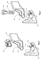
- the frame 50 is shaped to provide an aperture 59 for receiving either of the power fold mechanism 60 shown in Fig 2 or a manual fold insert (comprised of a spring 58' and a spigot 29') as shown in Fig 3 .
- a manual fold insert compact of a spring 58' and a spigot 29'
- the aperture 59 is at least partially inboard in a radial direction with respect to the detent 57 on the frame 50 whereby at least a clutch mechanism of the power fold mechanism 60 can be accommodated to operate on a smaller radius (measured from the mirror head axis 53 shown in Fig 1 ) than that of the detent features 57.
- the reduction of the power fold 60 and the implemented clutch mechanism in the inner radius of the aperture is on the one side a way to implement a common design for power fold and none power fold use and the reduce mechanical forces to the clutch.
- the power fold mechanism 60 has a spigot 29, a housing 40, a spring 58, a drive train 70 (best shown in Fig 6 ) and a clutch mechanism.
- the spigot 29 holds the spring 58 compressed between the base 21 and the housing 40 and hence the frame 50, thereby holding the detent formed by detent features 24 and 57 engaged against at least wind loads.
- the clutch mechanism comprises a pair of opposed clutching faces (which will be described later) biased together by the spring 58. The clutching faces connect the drive train 70 to the base 21 when the drive train is driving.
- a manual fold insert as illustrated in Fig 3 can be provided instead of the power fold mechanism 60.
- the manual fold insert simply comprises a spigot 29' and a spring 58'.
- the spigot 29' holds the spring 58' compressed between the base 21 and the frame 50 thereby holding the detent formed by detent feature 57 on the frame 50 and detent features 24 on the base 21 engaged against at least wind loads.
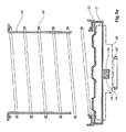
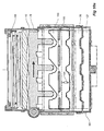
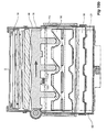
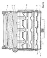
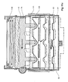
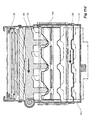
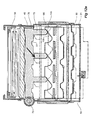
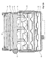
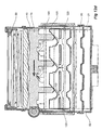
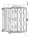
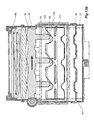
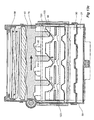
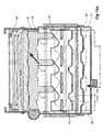
- Fig 9a shows diagrammatically a base 21 (that typically forms part of a mirror bracket directly mountable to a vehicle), and a mirror head frame 50 rotatably mounted to the base 21 for rotation about a mirror head axis 53.
- a detent that is operably interposed between the base 21 and the frame 50 is formed by detent features 24 and 57 located on the mirror base 21 and frame 50 respectively.
- the detent has a drive position, the position shown in diagrammatic Fig 9a and Fig 1 .
- a primary spring 58 acts between the frame 50 and the base 21 by virtue of its compression between a retainer 30 connected to a spigot 29 which fits by a bayonet fitting at its lower end into the base 21.
- the primary spring 58 acts in a direction parallel to the mirror head axis 53 and holds the detent engaged in the detent position.
- the power fold mechanism is operably interposed between the mirror base 21 and frame 50 and comprises a housing 40 installable into the mirror head frame 50 for rotation therewith.
- the power fold mechanism also comprises a drive train 70 that includes a motor 75 mounted to the housing.
- the drive train includes a worm gear 72 that engages a drive gear 78 that has a plurality of circumferentially spaced apart axially extending protrusions 79.
- the power fold mechanism also includes a main ramp ring 100 interposed between the drive gear 78 and the base 21.
- the main ramp ring 100 has a plurality of ramp recesses 103 for receiving respective protrusions 79 of the drive gear 78 such that relative rotation between the drive gear 78 and the main ramp ring 100 results in their relative axial displacement.
- the main ramp ring 100 is operatively connected to the base so as to provide a clutch.
- the clutch has an engaged position where the main ramp ring 100 is rotationally fixed with respect to the base 21 and a disengaged position in which the main ramp ring 100 is rotatable with respect to the base 21 about axis 53.
- a drive disc 90 connects into the base 21.
- the drive disc 90 has a clutch face 94 comprising clutch ramps 95 arranged to engage with a corresponding clutching face and clutching ramps 107 and 109 on the underside of the main ramp ring 100 (shown in fig 9 , Fig 9a and Fig 8c ).
- a manual fold torque transmission member in the form of a manual fold ring is splined to the housing 40 to allow relative axial movement but not relative rotational movement with respect to the housing 40.
- the manual fold ring has an engaged position in which it engages the main ramp ring 100 such that the main ramp ring 100 rotates with the housing 40.
- the manual fold ring 120 also has a disengaged position in which the main ramp ring 100 is not constrained to rotate with the housing 40.
- An electric stall ring 110 is provided to stop the drive gear 78 at the drive position during electric folding from the park position to the drive position. This reduces delay in the operation of the mechanism.
- the electric stall ring 110 also positions the drive gear 78 to prevent it engaging the main ramp ring 100 during manual folding and thus prevents load being transferred to the drive gear 78 during the folding.
- the electric stall ring 110 is splined to the housing 40 by way of a spline key that sits in the spline key way 49 as shown in Figs 8a and 8b .
- the electric stall ring 110 solves a problem that occurs with some powerfold mechanisms. It prevents the powerfold mechanism driving "through the clutch". That is it stops the powerfold mechanism overcoming the holding torque of the clutch. This is because the electric stall ring produces a force loop with the worm gear 72 pushing on the housing 40, the gears 72 pushing on the drive gear 78, the drive gear 78 pushing on the electric stall ring 110 and the electric stall ring 110 pushing back onto the housing 40 (the electric stall ring 110 is splined to the housing 40). Thus the stall torque that is generated once the stall position is reached is confined to the drive train and the housing and does not transfer to the clutch.
- the designer can design the system to use a higher drive torque, even a drive torque higher than the clutch torque.
- the drive torque is less than the clutch torque.
- employing the electric stall ring 110 even if the system wears, the powerfold system will not drive "through the clutch".
- the system employing electric stall ring 110 also has the advantage that the clutch system is not stressed as frequently as would otherwise be the case.
- a secondary ramp ring 220 is interposed between the primary spring 58 and the drive gear 78.
- the secondary ramp ring transfers spring force from the spring 58 to the drive gear 78.
- the helper ramps 224 of the secondary ramp ring 220 reduce the torque required to overcome the detents during electric operation.
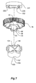
- the reaction faces 222 of the secondary ramp ring transmit drive train reaction torque to the base for electric fold out (the secondary ramp ring 220 is splined to the spigot 29 by virtue of spline keys 229 most clearly shown in Fig 7 .
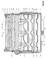
- Fig 6 it can be seen that there are a number of springs aside from the primary spring 58.
- These springs include an electric stall spring 111 that biases the electric stall ring 110 upwards and into engagement with the drive gear 78.
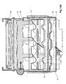
- a manual fold spring 130 is provided to bias the manual fold ring 120 upwards and into engagement with the main ramp ring 100 (to the position shown in Fig 9a ). This spring is shown in Fig 8a .
- the spring 130 includes projections 131 that act to restrain movement of the electric stall ring 110 (this is shown diagrammatically in Fig 9a for instance).
- the manual fold spring 130 includes a fold 132. It is this fold 132 that biases the manual fold ring 120 upwards into engagement with the main ramp ring 100.
- a main ramp ring spring 101 is also provided to bias the main ramp ring 100 downwards.
- Fig 3 and Figs 5a to 5c manual folding of the mirror head and hence frame 50 with respect to the mirror bracket and hence base 21 can be seen.
- the detent features 57 on the frame 50 ride up the detent features 24 on the mirror base as is shown progressively from Figs 5a to 5b .
- the spring 58' is compressed.
- Fig 5c shows the frame park stop 54 reaching and stoping at the base rearward fold (park) end stop 28.
- Fig 11c it can be seen that the main ramp ring 100 has moved up inside the power fold mechanism without contacting the gear drive 78 or its protrusions 79. Furthermore, it can be seen that the electric stall ring 110 has disengaged from the drive gear 78 for subsequent electric function.
- Figs 12a to 12e electric fold out from the park position to the drive (or deployed) position will now be described.
- power is applied to the motor 75 which results in torque at the worm gear 72.
- Worm gear 72 meshes with drive gear 78 and rotates gear drive 78 down the main ramp ring 100 thereby lowering the frame 50 down towards the base 21.
- the drive gear main ramp 86 (most clearly shown in Fig 7 ) rides down the corresponding main ramp ring 106 as is shown progressively in Figs 12a and 12b .
- a reaction torque stopping rotation of the drive gear 78 is created at the interface of the reaction face 82 of the drive gear 78 with the reaction face 222 of the secondary ramp ring 220 as illustrated in Fig 12b .
- the drive gear 78 now held from further movement with respect to the secondary ramp ring 220 and hence the base 21, the worm gear 72 and hence the housing 40, the frame 50 and the entire mirror head 51 rotates with respect to the base 21 as is illustrated in the transition from Fig 12b to 12c .
- Fig 12c it can be seen that the frame 50 is reaching the detent form by detent features 57 and 24.
- the drive gear 78 rotates with respect to the housing 40 such that the electric stall ring 110 and the manual fold ring 120 both re-engage.
- the electric stall ring stop 115 engages the drive gear electric fold ring stop 81 as is shown progressively from Fig 12d to 12e .
- the manual fold ring pushing face 122 moves up into position adjacent the main ramp ring push face 102, leaving the mechanism stalled in the drive position shown in Fig 12e .
- Figs 13a to 13f electric fold in from the drive to the park position will now be described.
- power is applied to the motor 75 causing the worm gear 72 to rotate the drive gear 78.
- the ramp 88 on the protrusion 79 of the drive gear 78 has reached the ramp 123 of the manual fold ring 120.
- the drive gear 78 continues to rotate with respect to the housing and hence the manual fold ring 120, it starts to push the manual fold ring 120 downwards against the weak spring force provided by the manual fold spring 130 most clearly shown diagrammatically in Fig 9b .
- Fig 13c it can be seen that the manual fold ring 120 has disengaged from the main ramp ring so that the manual fold ring 120 is effectively no longer splined or otherwise locked to rotate with the housing 40.
- Fig 13e shows the park stop 54 of the frame 50 reaching the base rearward folds (park) end stop 28.
- the drive gear 78 rides up the main ramp ring 100 to take up any manufacturing clearances or tolerances lifting the frame 50 up and stalling the mechanism in a position shown in Fig 13f .
- Figs 14a to 14e manual fold out of the mirror head back to the drive position after electric fold in will now be described.
- Figs 14a and 14b as a person pushes on the mirror head 51 and therefore the frame 50, this produces a force on the worm gear 72 which in turn pushes against the drive gear 78.
- the ramp ring 100 rides up the steep clutch ramp 107 until the knee 108 is reached as is shown in Fig 14b .
- the main ramp ring 100 now moves up under the action of spring 104 most clearly shown in Fig 9b .
- the frame 50 rotates to the drive position as is shown progressively from Figs 14c to 14e .
- the detents 24 and 57 can be seen re-engaging.
- the main ramp ring 100 also moves further upwards.
- Fig 10a an alternative manual fold torque transmission member is shown.
- an actuator 125 is provided. This actuator performs the same function that the ramp 123 performs in the manual fold ring 120 described with reference to Fig 13a for instance. That is, the actuator 125 actuates the manual fold torque transmission member 120 upwards and downwards so as to engage or disengage it with the main ramp ring 100.
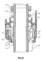
- FIG. 10b an alternative electric stall system 110 is shown.
- the relative rotational positions between the drive gear 78 and the electric fold ring 110 is sensed through elements 105 and 116 as shown in Fig 10b .
- Sensor elements 105 and 116 (which may include a limit switch) replace the electric stall ring ramps and stops 114 and 115 shown in Fig 8a .
- This alternative electric stall system detects a relative rotational position between the housing 40 and the drive gear 78 and stalls the drive gear 78 by cutting power to the motor in the position shown in Fig 12e .
- a conventional manual fold detent system is used which enhances vibration performance and manual folding functions. Furthermore, because the power fold drive train is only operably connected between the frame 50 and base 21 during electric operation, all loads, including wind load, road transmitted loads, and static loads are transferred from the frame 50 to the base 21 through the manual detent system and the power fold mechanism is isolated from these loads. As a result, the power fold drive train and other components do not have the same strength and rigidity requirements of a conventional power fold system.
- the operating logic of the power folding system described above is improved compared to prior art folding mirror heads. Combinations of manual and electric folding functions behave as expected, with the mirror head and frame being able to be returned to the drive position in one or two activations of a vehicle cabin mounted switch.
- a park position detent that engages after manual fold in is a useful, but not essential feature as it positively holds the mirror in the parked position. This is important during car washing and during loading of vehicles onto trucks, trains or other vehicles.
Landscapes
- Engineering & Computer Science (AREA)
- Multimedia (AREA)
- Mechanical Engineering (AREA)
- Rear-View Mirror Devices That Are Mounted On The Exterior Of The Vehicle (AREA)
Applications Claiming Priority (2)
| Application Number | Priority Date | Filing Date | Title |
|---|---|---|---|
| AU2008203505A AU2008203505B2 (en) | 2008-08-05 | 2008-08-05 | Vehicle mirror power fold mechanism |
| AU2009201083A AU2009201083A1 (en) | 2008-08-05 | 2009-03-18 | A foldable rear view mirror assembly for a vehicle |
Publications (2)
| Publication Number | Publication Date |
|---|---|
| EP2230131A1 true EP2230131A1 (de) | 2010-09-22 |
| EP2230131B1 EP2230131B1 (de) | 2011-05-18 |
Family
ID=41508076
Family Applications (2)
| Application Number | Title | Priority Date | Filing Date |
|---|---|---|---|
| EP09165505A Active EP2230131B1 (de) | 2008-08-05 | 2009-07-15 | Zusammenklappbare Rückspiegeleinheit für ein Fahrzeug |
| EP09165504.3A Not-in-force EP2159102B1 (de) | 2008-08-05 | 2009-07-15 | Fahrzeugspiegelantriebsklappmechanismus |
Family Applications After (1)
| Application Number | Title | Priority Date | Filing Date |
|---|---|---|---|
| EP09165504.3A Not-in-force EP2159102B1 (de) | 2008-08-05 | 2009-07-15 | Fahrzeugspiegelantriebsklappmechanismus |
Country Status (4)
| Country | Link |
|---|---|
| US (2) | US8366284B2 (de) |
| EP (2) | EP2230131B1 (de) |
| AT (1) | ATE509801T1 (de) |
| AU (2) | AU2008203505B2 (de) |
Cited By (7)
| Publication number | Priority date | Publication date | Assignee | Title |
|---|---|---|---|---|
| CN102862518A (zh) * | 2011-07-05 | 2013-01-09 | 市光工业株式会社 | 车辆用外侧镜装置 |
| EP2639110A1 (de) * | 2012-03-14 | 2013-09-18 | Magna Auteca AG | Antriebsanordnung für einen Außenrückspiegel eines Fahrzeugs |
| EP2639112A1 (de) * | 2012-03-14 | 2013-09-18 | Magna Auteca AG | Gruppe von Außenspiegeln mit unterschiedlichen Funktionen |
| EP2698280A1 (de) * | 2012-08-14 | 2014-02-19 | Fico Mirrors, S.A. | Faltspiegel mit Doppelarretierung |
| EP3139052A1 (de) | 2015-09-01 | 2017-03-08 | SMR Patents S.à.r.l. | Rutschkupplung für eine verstellvorrichtung und aussenspiegel für ein kraftfahrzeug mit einer verstellvorrichtung |
| US10940801B1 (en) | 2019-09-09 | 2021-03-09 | Motherson Innovations Company Limited | Actuating device for a component |
| EP4242063A4 (de) * | 2020-11-09 | 2024-08-21 | Ningbo Jingcheng Car Industry Co., Ltd. | Elektrische klappvorrichtung für aussenrückspiegel eines fahrzeugs |
Families Citing this family (57)
| Publication number | Priority date | Publication date | Assignee | Title |
|---|---|---|---|---|
| AU2008203505B2 (en) * | 2008-08-05 | 2011-06-09 | Smr Patents S.A.R.L. | Vehicle mirror power fold mechanism |
| US11498486B2 (en) | 2009-10-07 | 2022-11-15 | Magna Mirrors Of America, Inc. | Vehicular exterior rearview mirror assembly |
| US10261648B2 (en) | 2009-10-07 | 2019-04-16 | Magna Mirrors Of America, Inc. | Exterior rearview mirror assembly |
| JP5416568B2 (ja) * | 2009-12-11 | 2014-02-12 | 株式会社村上開明堂 | 手動格納式車両用ドアミラー |
| US12115913B2 (en) | 2010-02-10 | 2024-10-15 | Magna Mirrors Of America, Inc. | Vehicular exterior rearview mirror system |
| US9827913B2 (en) | 2010-02-10 | 2017-11-28 | Magna Mirrors Of America, Inc. | Exterior rearview mirror assembly |
| US12668184B2 (en) | 2010-02-10 | 2026-06-30 | Magna Mirrors Of America, Inc. | Vehicular exterior rearview mirror assembly |
| US11325535B2 (en) | 2010-02-10 | 2022-05-10 | Magna Mirrors Of America, Inc. | Exterior rearview mirror assembly |
| US9969334B2 (en) | 2010-02-10 | 2018-05-15 | Magna Mirrors Of America, Inc. | Exterior rearview mirror assembly |
| JP5389693B2 (ja) * | 2010-02-25 | 2014-01-15 | 株式会社村上開明堂 | 車両用ドアミラー |
| EP2439106B1 (de) * | 2010-10-08 | 2012-12-05 | SMR Patents S.à.r.l. | Antriebsklappmechanismus |
| JP5488429B2 (ja) * | 2010-11-26 | 2014-05-14 | 市光工業株式会社 | 車両用アウトサイドミラー装置 |
| US9067541B2 (en) | 2011-10-31 | 2015-06-30 | Magna Mirrors Of America, Inc. | Exterior mirror assembly with actuator |
| ES2656093T5 (en) | 2012-02-22 | 2026-05-14 | Magna Mirrors Of America Inc | Exterior rearview mirror assembly |
| JP5970911B2 (ja) * | 2012-03-28 | 2016-08-17 | 市光工業株式会社 | 車両用アウトサイドミラー装置 |
| DE102012016857A1 (de) | 2012-08-25 | 2013-03-21 | Daimler Ag | Außenrückspiegelanordnung für ein Fahrzeug |
| CN104175961B (zh) | 2013-05-23 | 2018-08-07 | 菲克米罗尔斯股份公司 | 用于机动车的可折叠后视镜 |
| WO2014205217A1 (en) | 2013-06-19 | 2014-12-24 | Magna International Inc. | Sealed actuator with internal clutching |
| US9676336B2 (en) | 2013-06-25 | 2017-06-13 | Magna Mirrors Of America, Inc. | Exterior rearview mirror assembly for vehicle |
| US9487142B2 (en) | 2013-06-25 | 2016-11-08 | Magna Mirrors Of America, Inc. | Rearview mirror assembly for vehicle |
| CN103693148B (zh) * | 2013-11-25 | 2016-02-17 | 东莞威信运动用品有限公司 | 马达驱动装置及手自一体的电动车折叠装置 |
| EP2902263B1 (de) | 2014-02-04 | 2018-04-11 | Fico Mirrors France S.A.S. | Rückspiegelanordnung für Kraftfahrzeuge |
| CA2939281C (en) | 2014-03-21 | 2020-03-24 | Magna International Inc. | Deployable aerodynamic bed cover system |
| US10189517B2 (en) | 2014-03-21 | 2019-01-29 | Magna Exteriors, Inc. | Deployable aerodynamic side panel system |
| US10046704B2 (en) | 2014-05-14 | 2018-08-14 | Fico Mirrors, S.A.U. | Fold rearview mirror assembly for motor vehicles |
| KR102470561B1 (ko) * | 2014-06-11 | 2022-11-25 | 마그나 익스테리어즈 인크. | 능동형 전방 디플렉터 |
| EP3524497B1 (de) | 2014-06-11 | 2020-06-24 | Magna Exteriors Inc. | Aktiver frontdeflektor |
| US9796334B2 (en) | 2014-06-13 | 2017-10-24 | Magna Mirrors Of America, Inc. | Exterior rearview mirror assembly for vehicle |
| CN105034957B9 (zh) * | 2015-08-22 | 2023-11-17 | 宁波精成车业有限公司 | 用于汽车外后视镜的电动折叠装置 |
| JP6618415B2 (ja) * | 2016-04-08 | 2019-12-11 | 株式会社東海理化電機製作所 | 車両用視認装置 |
| KR102461245B1 (ko) | 2016-12-16 | 2022-11-01 | 젠텍스 코포레이션 | 접는 외부 디스플레이 미러 |
| US10730436B2 (en) | 2016-12-30 | 2020-08-04 | Gentex Corporation | Vehicular outside rearview assembly |
| DE102017002578A1 (de) * | 2017-03-16 | 2018-09-20 | Man Truck & Bus Ag | Abklappvorrichtung für ein Spiegelersatzsystem |
| JP6983259B2 (ja) * | 2017-05-24 | 2021-12-17 | エスエムアール・パテンツ・ソシエテ・ア・レスポンサビリテ・リミテ | ピボットジョイントシステムおよびそれを備えたリアビューデバイス |
| WO2019035078A1 (en) | 2017-08-17 | 2019-02-21 | Magna Mirrors Of America, Inc. | RACING ACTUATOR FOR EXTERIOR MIRROR |
| CN111032431B (zh) | 2017-08-23 | 2023-04-18 | 麦格纳镜片美国有限公司 | 外部后视镜组件 |
| US11351919B2 (en) | 2018-05-24 | 2022-06-07 | Magna Mirrors Of America, Inc. | Exterior rearview mirror assembly |
| JP7087776B2 (ja) * | 2018-07-26 | 2022-06-21 | 市光工業株式会社 | 車両用アウトサイドミラー装置の電動格納ユニット、車両用アウトサイドミラー装置 |
| ES2781124B2 (es) * | 2019-02-26 | 2021-02-25 | Compania Levantina De Reductores S L | Mecanismo de rotacion de espejo retrovisor exterior para vehiculos y espejo retrovisor que lo incluye |
| NL2023038B1 (nl) * | 2019-04-30 | 2020-11-23 | Mci Mirror Controls Int Netherlands B V | Verstelinstrument |
| US11235704B2 (en) * | 2019-08-13 | 2022-02-01 | Motherson Innovations Company Limited | Rearview device with detent assembly |
| WO2021073712A1 (en) | 2019-10-14 | 2021-04-22 | Volvo Truck Corporation | Brake disc and a vehicle |
| EP4045812B1 (de) * | 2019-10-14 | 2023-08-16 | Volvo Truck Corporation | Bremsscheibe und fahrzeug |
| WO2021073711A1 (en) | 2019-10-14 | 2021-04-22 | Volvo Truck Corporation | Brake disc and a vehicle |
| US11396264B2 (en) | 2020-02-20 | 2022-07-26 | Magna Mirrors Of America, Inc. | Powerfold actuator for exterior mirror |
| NL2025061B1 (en) * | 2020-03-05 | 2021-10-14 | Mci Mirror Controls Int Netherlands B V | Adjustment device, and method for assembling |
| DE102020108931B4 (de) | 2020-03-31 | 2022-11-10 | Motherson Innovations Company Limited | Membransensorvorrichtung zur Positionserfassung, Antriebseinheit, Rückblickvorrichtung und Fahrzeug |
| TR202013442A2 (tr) * | 2020-08-26 | 2020-12-21 | Feka Otomotiv Mamuelleri Sanayi Ve Ticaret Anonim Sirketi | Di̇ki̇z aynalari i̇çi̇n kullanilan bi̇r katlama mekani̇zmasi |
| US11628772B2 (en) | 2020-10-28 | 2023-04-18 | Magna Mirrors Of America, Inc. | Powerfold actuator for exterior mirror |
| US12246648B2 (en) | 2021-01-19 | 2025-03-11 | Magna Mirrors Of America, Inc. | Vehicular exterior rearview mirror assembly with locking feature |
| CN119489745B (zh) * | 2021-02-09 | 2026-01-09 | 福州聚丰汽车零部件有限公司 | 一种折叠驱动装置 |
| WO2022226525A1 (en) | 2021-04-23 | 2022-10-27 | Magna Mirrors Of America, Inc. | Powerfold actuator for exterior mirror |
| US12351108B2 (en) | 2021-07-09 | 2025-07-08 | Magna Mirrors Of America, Inc. | Vehicular exterior rearview mirror assembly with extendable and retractable mirror head |
| CN114179897B (zh) * | 2021-12-20 | 2023-03-07 | 延锋国际座椅系统有限公司 | 一种折叠方向盘 |
| EP4238827B1 (de) * | 2022-03-04 | 2025-01-22 | Ficomirrors, S.A. | Klappbare aktuatorabdeckungsanordnung |
| KR20230140190A (ko) * | 2022-03-29 | 2023-10-06 | 주식회사 에스엘미러텍 | 차량용 구동 장치 |
| DE102023102059B3 (de) * | 2023-01-27 | 2024-07-18 | Motherson Innovations Company Limited | Rückblickvorrichtung und Fahrzeug |
Citations (6)
| Publication number | Priority date | Publication date | Assignee | Title |
|---|---|---|---|---|
| EP0644084A1 (de) * | 1993-09-03 | 1995-03-22 | Ichikoh Industries Limited | Rückspiegelsystem für Kraftfahrzeuge |
| US6022113A (en) | 1997-07-30 | 2000-02-08 | Gebr Buhler Nachfolger Gmbh | External rearview mirror for automobiles |
| JP2002193037A (ja) * | 2000-12-27 | 2002-07-10 | Sakae Riken Kogyo Co Ltd | 格納機構付きドアミラー装置 |
| US20080253008A1 (en) * | 2007-04-10 | 2008-10-16 | Milo Tseng | Foldable Exterior Rearview Mirror For Motor Vehicle |
| WO2009035931A1 (en) * | 2007-09-15 | 2009-03-19 | Heinrich Wilheim A | Universal folding bracket assembly for either manual fold or power fold rearview mirrors |
| EP2159102A1 (de) * | 2008-08-05 | 2010-03-03 | SMR PATENTS S.à.r.l. | Fahrzeugspiegelantriebsklappmechanismus |
Family Cites Families (32)
| Publication number | Priority date | Publication date | Assignee | Title |
|---|---|---|---|---|
| US2087521A (en) * | 1934-10-29 | 1937-07-20 | Mazzola Antonino | Hair curling device |
| US2956642A (en) * | 1958-12-23 | 1960-10-18 | Gen Motors Corp | Camshaft and bearing lubricating means |
| US3220254A (en) * | 1963-08-30 | 1965-11-30 | Marquardt Corp | Two-phase fluid flowmeter |
| US4021867A (en) * | 1975-09-08 | 1977-05-10 | Maxwell Jr Oscar Benton | Convertible cradle |
| US4037889A (en) * | 1976-06-14 | 1977-07-26 | Piatt James A | Journal bearing |
| US4262975A (en) * | 1979-10-01 | 1981-04-21 | Mechanical Technology Incorporated | Compliant journal bearing with angular stiffness gradient |
| DE3123990C2 (de) * | 1981-06-19 | 1986-04-10 | M.A.N.- Roland Druckmaschinen AG, 6050 Offenbach | Einstellvorrichtung für Farb- u. Feuchtwalzen an Druckmaschinen |
| US4687167A (en) * | 1985-10-23 | 1987-08-18 | Skalka Gerald P | Multi-position computer support |
| JPH07110597B2 (ja) * | 1987-02-10 | 1995-11-29 | 株式会社小糸製作所 | 電動格納型ドアミラ− |
| JPH0249638U (de) * | 1988-09-30 | 1990-04-06 | ||
| JPH04136949U (ja) * | 1991-06-17 | 1992-12-21 | 株式会社村上開明堂 | 可倒式ドアミラー |
| JP2604693Y2 (ja) * | 1992-09-16 | 2000-05-22 | 株式会社村上開明堂 | 電動格納式ドアミラー |
| US5734517A (en) * | 1993-12-15 | 1998-03-31 | Poong Jeong Ind. Co., Ltd. | Device for regulating motor-driven foldable rear view mirror of automobile |
| NL1003144C2 (nl) * | 1996-05-15 | 1997-11-18 | Iku Holding Montfoort Bv | Elektrisch bedienbare scharnieractuator, en buitenspiegel met elektrisch bedienbaar scharniermechanisme. |
| EP0866216B1 (de) * | 1997-03-21 | 2003-05-07 | Stefan Battlogg | Nockenwelle |
| DE69822701T2 (de) * | 1997-05-29 | 2005-01-13 | Schefenacker Vision Systems Australia Pty Ltd, Lonsdale | Betätigungsmechanismus für einen Rückblickspiegel |
| JP3795194B2 (ja) * | 1997-08-20 | 2006-07-12 | 株式会社東海理化電機製作所 | ドアミラーの電動格納装置 |
| DE10006913B4 (de) * | 2000-02-16 | 2005-12-22 | Bühler Motor GmbH | Außenrückblickspiegel für ein Kraftfahrzeug |
| DE10009670B4 (de) * | 2000-02-29 | 2005-08-04 | Bühler Motor GmbH | Außenrückblickspiegel für ein Kraftfahrzeug |
| US6257731B1 (en) * | 2000-08-17 | 2001-07-10 | Jaeil Engineering Co., Ltd. | Connections device of actuator for side mirrors of automobile |
| US7070287B2 (en) * | 2002-04-23 | 2006-07-04 | Magna Donnelly Mirrors North America L.L.C. | Vehicular mirror system with at least one of power-fold and power-extend functionality |
| TWI232187B (en) * | 2003-06-28 | 2005-05-11 | Chaw Khong Co Ltd | Electrical operable pivoting back-mirror device |
| DE602005003927T2 (de) * | 2004-02-06 | 2008-12-18 | Eaton Automotive B.V. | Gelenkstellglied und verfahren zur einstellung von zwei teilen eines gelenks eines gelenkstellglieds bezüglich einander |
| NL1025437C2 (nl) | 2004-02-06 | 2005-08-09 | Iku Holding Montfoort Bv | Scharnieractuator. |
| NL1026002C2 (nl) * | 2004-04-22 | 2005-10-25 | Iku Holding Montfoort Bv | Scharnieractuator, in het bijzonder voor een buitenspiegeleenheid. |
| US7303294B1 (en) * | 2004-09-14 | 2007-12-04 | Magna Donnelly Mirrors North America L.L.C. | Vehicle mirror system with reduced friction actuation and movement |
| GB2424257A (en) * | 2005-03-18 | 2006-09-20 | Mechadyne Plc | Single cam phaser camshaft with adjustable connections between the inner shaft and associated cam lobes |
| JP4193910B2 (ja) * | 2006-06-29 | 2008-12-10 | ダイキン工業株式会社 | 冷媒分流器一体化構造の膨張弁 |
| US7887202B1 (en) * | 2007-06-22 | 2011-02-15 | Magna Mirrors Of America, Inc. | Vehicular mirror system with dual detent powerfold assembly |
| JP2011509452A (ja) * | 2007-12-19 | 2011-03-24 | クラスタード システムズ カンパニー | 接触冷却される電子モジュールのための冷却システム |
| US20090225514A1 (en) * | 2008-03-10 | 2009-09-10 | Adrian Correa | Device and methodology for the removal of heat from an equipment rack by means of heat exchangers mounted to a door |
| US8164901B2 (en) * | 2008-04-16 | 2012-04-24 | Julius Neudorfer | High efficiency heat removal system for rack mounted computer equipment |
-
2008
- 2008-08-05 AU AU2008203505A patent/AU2008203505B2/en not_active Ceased
-
2009
- 2009-03-18 AU AU2009201083A patent/AU2009201083A1/en not_active Abandoned
- 2009-07-15 AT AT09165505T patent/ATE509801T1/de not_active IP Right Cessation
- 2009-07-15 EP EP09165505A patent/EP2230131B1/de active Active
- 2009-07-15 EP EP09165504.3A patent/EP2159102B1/de not_active Not-in-force
- 2009-08-05 US US12/536,013 patent/US8366284B2/en active Active
- 2009-08-05 US US12/536,042 patent/US8366285B2/en active Active
Patent Citations (6)
| Publication number | Priority date | Publication date | Assignee | Title |
|---|---|---|---|---|
| EP0644084A1 (de) * | 1993-09-03 | 1995-03-22 | Ichikoh Industries Limited | Rückspiegelsystem für Kraftfahrzeuge |
| US6022113A (en) | 1997-07-30 | 2000-02-08 | Gebr Buhler Nachfolger Gmbh | External rearview mirror for automobiles |
| JP2002193037A (ja) * | 2000-12-27 | 2002-07-10 | Sakae Riken Kogyo Co Ltd | 格納機構付きドアミラー装置 |
| US20080253008A1 (en) * | 2007-04-10 | 2008-10-16 | Milo Tseng | Foldable Exterior Rearview Mirror For Motor Vehicle |
| WO2009035931A1 (en) * | 2007-09-15 | 2009-03-19 | Heinrich Wilheim A | Universal folding bracket assembly for either manual fold or power fold rearview mirrors |
| EP2159102A1 (de) * | 2008-08-05 | 2010-03-03 | SMR PATENTS S.à.r.l. | Fahrzeugspiegelantriebsklappmechanismus |
Cited By (12)
| Publication number | Priority date | Publication date | Assignee | Title |
|---|---|---|---|---|
| CN102862518A (zh) * | 2011-07-05 | 2013-01-09 | 市光工业株式会社 | 车辆用外侧镜装置 |
| CN102862518B (zh) * | 2011-07-05 | 2016-04-27 | 市光工业株式会社 | 车辆用外侧镜装置 |
| EP2639110A1 (de) * | 2012-03-14 | 2013-09-18 | Magna Auteca AG | Antriebsanordnung für einen Außenrückspiegel eines Fahrzeugs |
| EP2639112A1 (de) * | 2012-03-14 | 2013-09-18 | Magna Auteca AG | Gruppe von Außenspiegeln mit unterschiedlichen Funktionen |
| WO2013135756A1 (de) * | 2012-03-14 | 2013-09-19 | Magna Auteca Ag | ANTRIEBSANORDNUNG FÜR EINEN AUßENRÜCKSPIEGEL EINES FAHRZEUGS |
| KR20130105506A (ko) * | 2012-03-14 | 2013-09-25 | 마그나 아우테카 악티엔게젤샤프트 | 외부 미러의 그룹 |
| KR101991136B1 (ko) | 2012-03-14 | 2019-06-19 | 마그나 아우테카 악티엔게젤샤프트 | 외부 미러의 그룹 |
| EP2698280A1 (de) * | 2012-08-14 | 2014-02-19 | Fico Mirrors, S.A. | Faltspiegel mit Doppelarretierung |
| EP3139052A1 (de) | 2015-09-01 | 2017-03-08 | SMR Patents S.à.r.l. | Rutschkupplung für eine verstellvorrichtung und aussenspiegel für ein kraftfahrzeug mit einer verstellvorrichtung |
| US10302144B2 (en) | 2015-09-01 | 2019-05-28 | SMR Patents S.à.r.l. | Sliding clutch for an adjustment device and side-view mirror for a motor vehicle having an adjustment device |
| US10940801B1 (en) | 2019-09-09 | 2021-03-09 | Motherson Innovations Company Limited | Actuating device for a component |
| EP4242063A4 (de) * | 2020-11-09 | 2024-08-21 | Ningbo Jingcheng Car Industry Co., Ltd. | Elektrische klappvorrichtung für aussenrückspiegel eines fahrzeugs |
Also Published As
| Publication number | Publication date |
|---|---|
| US20100238570A1 (en) | 2010-09-23 |
| US8366285B2 (en) | 2013-02-05 |
| US20100060024A1 (en) | 2010-03-11 |
| US8366284B2 (en) | 2013-02-05 |
| EP2159102A1 (de) | 2010-03-03 |
| ATE509801T1 (de) | 2011-06-15 |
| AU2009201083A1 (en) | 2010-03-04 |
| AU2008203505B2 (en) | 2011-06-09 |
| EP2230131B1 (de) | 2011-05-18 |
| AU2008203505A1 (en) | 2010-02-25 |
| EP2159102B1 (de) | 2013-10-23 |
Similar Documents
| Publication | Publication Date | Title |
|---|---|---|
| EP2230131B1 (de) | Zusammenklappbare Rückspiegeleinheit für ein Fahrzeug | |
| US7172298B2 (en) | Power fold mechanism for vehicle mirrors | |
| CN112389331B (zh) | 用于后视镜翻折和升降的组合致动器、后视装置和车辆 | |
| US20240367585A1 (en) | Vehicular exterior mirror with actuator | |
| EP2439106B1 (de) | Antriebsklappmechanismus | |
| US11634077B2 (en) | Powerfold actuator for exterior mirror | |
| US6022113A (en) | External rearview mirror for automobiles | |
| US11628772B2 (en) | Powerfold actuator for exterior mirror | |
| US10703280B2 (en) | Actuator mechanism for a fold rear-view mirror assembly | |
| US6929372B2 (en) | Power fold mechanism for double arm mirrors | |
| CN106458099A (zh) | 机动车辆的折叠式后视镜组件 | |
| US6863407B1 (en) | Mirror parking mechanism | |
| WO2000041914A1 (en) | A mirror rotation mechanism | |
| KR20250175458A (ko) | 아웃사이드 미러 폴딩구조 | |
| CN121989804A (zh) | 致动器组件、外部后视镜和车辆 | |
| AU2423600A (en) | A mirror rotation mechanism |
Legal Events
| Date | Code | Title | Description |
|---|---|---|---|
| PUAI | Public reference made under article 153(3) epc to a published international application that has entered the european phase |
Free format text: ORIGINAL CODE: 0009012 |
|
| 17P | Request for examination filed |
Effective date: 20100729 |
|
| AK | Designated contracting states |
Kind code of ref document: A1 Designated state(s): AT BE BG CH CY CZ DE DK EE ES FI FR GB GR HR HU IE IS IT LI LT LU LV MC MK MT NL NO PL PT RO SE SI SK SM TR |
|
| AX | Request for extension of the european patent |
Extension state: AL BA RS |
|
| RIC1 | Information provided on ipc code assigned before grant |
Ipc: B60R 1/074 20060101AFI20101008BHEP |
|
| GRAP | Despatch of communication of intention to grant a patent |
Free format text: ORIGINAL CODE: EPIDOSNIGR1 |
|
| GRAS | Grant fee paid |
Free format text: ORIGINAL CODE: EPIDOSNIGR3 |
|
| GRAA | (expected) grant |
Free format text: ORIGINAL CODE: 0009210 |
|
| REG | Reference to a national code |
Ref country code: GB Ref legal event code: FG4D |
|
| REG | Reference to a national code |
Ref country code: CH Ref legal event code: EP |
|
| REG | Reference to a national code |
Ref country code: IE Ref legal event code: FG4D |
|
| REG | Reference to a national code |
Ref country code: DE Ref legal event code: R096 Ref document number: 602009001307 Country of ref document: DE Effective date: 20110630 |
|
| REG | Reference to a national code |
Ref country code: NL Ref legal event code: VDEP Effective date: 20110518 |
|
| PG25 | Lapsed in a contracting state [announced via postgrant information from national office to epo] |
Ref country code: PT Free format text: LAPSE BECAUSE OF FAILURE TO SUBMIT A TRANSLATION OF THE DESCRIPTION OR TO PAY THE FEE WITHIN THE PRESCRIBED TIME-LIMIT Effective date: 20110919 Ref country code: SE Free format text: LAPSE BECAUSE OF FAILURE TO SUBMIT A TRANSLATION OF THE DESCRIPTION OR TO PAY THE FEE WITHIN THE PRESCRIBED TIME-LIMIT Effective date: 20110518 Ref country code: NO Free format text: LAPSE BECAUSE OF FAILURE TO SUBMIT A TRANSLATION OF THE DESCRIPTION OR TO PAY THE FEE WITHIN THE PRESCRIBED TIME-LIMIT Effective date: 20110818 Ref country code: LT Free format text: LAPSE BECAUSE OF FAILURE TO SUBMIT A TRANSLATION OF THE DESCRIPTION OR TO PAY THE FEE WITHIN THE PRESCRIBED TIME-LIMIT Effective date: 20110518 Ref country code: HR Free format text: LAPSE BECAUSE OF FAILURE TO SUBMIT A TRANSLATION OF THE DESCRIPTION OR TO PAY THE FEE WITHIN THE PRESCRIBED TIME-LIMIT Effective date: 20110518 |
|
| PG25 | Lapsed in a contracting state [announced via postgrant information from national office to epo] |
Ref country code: SI Free format text: LAPSE BECAUSE OF FAILURE TO SUBMIT A TRANSLATION OF THE DESCRIPTION OR TO PAY THE FEE WITHIN THE PRESCRIBED TIME-LIMIT Effective date: 20110518 Ref country code: GR Free format text: LAPSE BECAUSE OF FAILURE TO SUBMIT A TRANSLATION OF THE DESCRIPTION OR TO PAY THE FEE WITHIN THE PRESCRIBED TIME-LIMIT Effective date: 20110819 Ref country code: LV Free format text: LAPSE BECAUSE OF FAILURE TO SUBMIT A TRANSLATION OF THE DESCRIPTION OR TO PAY THE FEE WITHIN THE PRESCRIBED TIME-LIMIT Effective date: 20110518 Ref country code: BE Free format text: LAPSE BECAUSE OF FAILURE TO SUBMIT A TRANSLATION OF THE DESCRIPTION OR TO PAY THE FEE WITHIN THE PRESCRIBED TIME-LIMIT Effective date: 20110518 Ref country code: IS Free format text: LAPSE BECAUSE OF FAILURE TO SUBMIT A TRANSLATION OF THE DESCRIPTION OR TO PAY THE FEE WITHIN THE PRESCRIBED TIME-LIMIT Effective date: 20110918 Ref country code: AT Free format text: LAPSE BECAUSE OF FAILURE TO SUBMIT A TRANSLATION OF THE DESCRIPTION OR TO PAY THE FEE WITHIN THE PRESCRIBED TIME-LIMIT Effective date: 20110518 Ref country code: CY Free format text: LAPSE BECAUSE OF FAILURE TO SUBMIT A TRANSLATION OF THE DESCRIPTION OR TO PAY THE FEE WITHIN THE PRESCRIBED TIME-LIMIT Effective date: 20110518 Ref country code: ES Free format text: LAPSE BECAUSE OF FAILURE TO SUBMIT A TRANSLATION OF THE DESCRIPTION OR TO PAY THE FEE WITHIN THE PRESCRIBED TIME-LIMIT Effective date: 20110829 Ref country code: FI Free format text: LAPSE BECAUSE OF FAILURE TO SUBMIT A TRANSLATION OF THE DESCRIPTION OR TO PAY THE FEE WITHIN THE PRESCRIBED TIME-LIMIT Effective date: 20110518 |
|
| PG25 | Lapsed in a contracting state [announced via postgrant information from national office to epo] |
Ref country code: NL Free format text: LAPSE BECAUSE OF FAILURE TO SUBMIT A TRANSLATION OF THE DESCRIPTION OR TO PAY THE FEE WITHIN THE PRESCRIBED TIME-LIMIT Effective date: 20110518 Ref country code: MT Free format text: LAPSE BECAUSE OF FAILURE TO SUBMIT A TRANSLATION OF THE DESCRIPTION OR TO PAY THE FEE WITHIN THE PRESCRIBED TIME-LIMIT Effective date: 20110518 |
|
| PG25 | Lapsed in a contracting state [announced via postgrant information from national office to epo] |
Ref country code: CZ Free format text: LAPSE BECAUSE OF FAILURE TO SUBMIT A TRANSLATION OF THE DESCRIPTION OR TO PAY THE FEE WITHIN THE PRESCRIBED TIME-LIMIT Effective date: 20110518 Ref country code: EE Free format text: LAPSE BECAUSE OF FAILURE TO SUBMIT A TRANSLATION OF THE DESCRIPTION OR TO PAY THE FEE WITHIN THE PRESCRIBED TIME-LIMIT Effective date: 20110518 |
|
| PG25 | Lapsed in a contracting state [announced via postgrant information from national office to epo] |
Ref country code: PL Free format text: LAPSE BECAUSE OF FAILURE TO SUBMIT A TRANSLATION OF THE DESCRIPTION OR TO PAY THE FEE WITHIN THE PRESCRIBED TIME-LIMIT Effective date: 20110518 Ref country code: MC Free format text: LAPSE BECAUSE OF NON-PAYMENT OF DUE FEES Effective date: 20110731 Ref country code: SK Free format text: LAPSE BECAUSE OF FAILURE TO SUBMIT A TRANSLATION OF THE DESCRIPTION OR TO PAY THE FEE WITHIN THE PRESCRIBED TIME-LIMIT Effective date: 20110518 |
|
| PLBE | No opposition filed within time limit |
Free format text: ORIGINAL CODE: 0009261 |
|
| STAA | Information on the status of an ep patent application or granted ep patent |
Free format text: STATUS: NO OPPOSITION FILED WITHIN TIME LIMIT |
|
| 26N | No opposition filed |
Effective date: 20120221 |
|
| REG | Reference to a national code |
Ref country code: IE Ref legal event code: MM4A |
|
| PG25 | Lapsed in a contracting state [announced via postgrant information from national office to epo] |
Ref country code: IT Free format text: LAPSE BECAUSE OF FAILURE TO SUBMIT A TRANSLATION OF THE DESCRIPTION OR TO PAY THE FEE WITHIN THE PRESCRIBED TIME-LIMIT Effective date: 20110518 |
|
| REG | Reference to a national code |
Ref country code: DE Ref legal event code: R082 Ref document number: 602009001307 Country of ref document: DE Representative=s name: JONES DAY RECHTSANWAELTE PATENTANWAELTE, DE |
|
| REG | Reference to a national code |
Ref country code: DE Ref legal event code: R097 Ref document number: 602009001307 Country of ref document: DE Effective date: 20120221 |
|
| PG25 | Lapsed in a contracting state [announced via postgrant information from national office to epo] |
Ref country code: IE Free format text: LAPSE BECAUSE OF NON-PAYMENT OF DUE FEES Effective date: 20110715 |
|
| PGFP | Annual fee paid to national office [announced via postgrant information from national office to epo] |
Ref country code: FR Payment date: 20120806 Year of fee payment: 4 Ref country code: DE Payment date: 20120720 Year of fee payment: 4 |
|
| PG25 | Lapsed in a contracting state [announced via postgrant information from national office to epo] |
Ref country code: MK Free format text: LAPSE BECAUSE OF FAILURE TO SUBMIT A TRANSLATION OF THE DESCRIPTION OR TO PAY THE FEE WITHIN THE PRESCRIBED TIME-LIMIT Effective date: 20110518 |
|
| PG25 | Lapsed in a contracting state [announced via postgrant information from national office to epo] |
Ref country code: SM Free format text: LAPSE BECAUSE OF FAILURE TO SUBMIT A TRANSLATION OF THE DESCRIPTION OR TO PAY THE FEE WITHIN THE PRESCRIBED TIME-LIMIT Effective date: 20110518 |
|
| PG25 | Lapsed in a contracting state [announced via postgrant information from national office to epo] |
Ref country code: LU Free format text: LAPSE BECAUSE OF NON-PAYMENT OF DUE FEES Effective date: 20110715 |
|
| PG25 | Lapsed in a contracting state [announced via postgrant information from national office to epo] |
Ref country code: BG Free format text: LAPSE BECAUSE OF FAILURE TO SUBMIT A TRANSLATION OF THE DESCRIPTION OR TO PAY THE FEE WITHIN THE PRESCRIBED TIME-LIMIT Effective date: 20110818 |
|
| PG25 | Lapsed in a contracting state [announced via postgrant information from national office to epo] |
Ref country code: TR Free format text: LAPSE BECAUSE OF FAILURE TO SUBMIT A TRANSLATION OF THE DESCRIPTION OR TO PAY THE FEE WITHIN THE PRESCRIBED TIME-LIMIT Effective date: 20110518 |
|
| PG25 | Lapsed in a contracting state [announced via postgrant information from national office to epo] |
Ref country code: HU Free format text: LAPSE BECAUSE OF FAILURE TO SUBMIT A TRANSLATION OF THE DESCRIPTION OR TO PAY THE FEE WITHIN THE PRESCRIBED TIME-LIMIT Effective date: 20110518 |
|
| REG | Reference to a national code |
Ref country code: CH Ref legal event code: PL |
|
| REG | Reference to a national code |
Ref country code: DE Ref legal event code: R119 Ref document number: 602009001307 Country of ref document: DE Effective date: 20140201 |
|
| REG | Reference to a national code |
Ref country code: FR Ref legal event code: ST Effective date: 20140331 |
|
| PG25 | Lapsed in a contracting state [announced via postgrant information from national office to epo] |
Ref country code: DE Free format text: LAPSE BECAUSE OF NON-PAYMENT OF DUE FEES Effective date: 20140201 Ref country code: CH Free format text: LAPSE BECAUSE OF NON-PAYMENT OF DUE FEES Effective date: 20130731 Ref country code: LI Free format text: LAPSE BECAUSE OF NON-PAYMENT OF DUE FEES Effective date: 20130731 |
|
| PG25 | Lapsed in a contracting state [announced via postgrant information from national office to epo] |
Ref country code: FR Free format text: LAPSE BECAUSE OF NON-PAYMENT OF DUE FEES Effective date: 20130731 |
|
| PGFP | Annual fee paid to national office [announced via postgrant information from national office to epo] |
Ref country code: GB Payment date: 20250724 Year of fee payment: 17 |