EP2698521B1 - Procédé destiné au fonctionnement d'un moteur à combustion interne - Google Patents
Procédé destiné au fonctionnement d'un moteur à combustion interne Download PDFInfo
- Publication number
- EP2698521B1 EP2698521B1 EP13003563.7A EP13003563A EP2698521B1 EP 2698521 B1 EP2698521 B1 EP 2698521B1 EP 13003563 A EP13003563 A EP 13003563A EP 2698521 B1 EP2698521 B1 EP 2698521B1
- Authority
- EP
- European Patent Office
- Prior art keywords
- cylinder
- specific
- max
- value
- internal combustion
- Prior art date
- Legal status (The legal status is an assumption and is not a legal conclusion. Google has not performed a legal analysis and makes no representation as to the accuracy of the status listed.)
- Active
Links
Images

Classifications
-
- F—MECHANICAL ENGINEERING; LIGHTING; HEATING; WEAPONS; BLASTING
- F02—COMBUSTION ENGINES; HOT-GAS OR COMBUSTION-PRODUCT ENGINE PLANTS
- F02D—CONTROLLING COMBUSTION ENGINES
- F02D19/00—Controlling engines characterised by their use of non-liquid fuels, pluralities of fuels, or non-fuel substances added to the combustible mixtures
- F02D19/02—Controlling engines characterised by their use of non-liquid fuels, pluralities of fuels, or non-fuel substances added to the combustible mixtures peculiar to engines working with gaseous fuels
- F02D19/021—Control of components of the fuel supply system
- F02D19/023—Control of components of the fuel supply system to adjust the fuel mass or volume flow
- F02D19/024—Control of components of the fuel supply system to adjust the fuel mass or volume flow by controlling fuel injectors
-
- F—MECHANICAL ENGINEERING; LIGHTING; HEATING; WEAPONS; BLASTING
- F02—COMBUSTION ENGINES; HOT-GAS OR COMBUSTION-PRODUCT ENGINE PLANTS
- F02D—CONTROLLING COMBUSTION ENGINES
- F02D29/00—Controlling engines, such controlling being peculiar to the devices driven thereby, the devices being other than parts or accessories essential to engine operation, e.g. controlling of engines by signals external thereto
- F02D29/06—Controlling engines, such controlling being peculiar to the devices driven thereby, the devices being other than parts or accessories essential to engine operation, e.g. controlling of engines by signals external thereto peculiar to engines driving electric generators
-
- F—MECHANICAL ENGINEERING; LIGHTING; HEATING; WEAPONS; BLASTING
- F02—COMBUSTION ENGINES; HOT-GAS OR COMBUSTION-PRODUCT ENGINE PLANTS
- F02D—CONTROLLING COMBUSTION ENGINES
- F02D35/00—Controlling engines, dependent on conditions exterior or interior to engines, not otherwise provided for
- F02D35/02—Controlling engines, dependent on conditions exterior or interior to engines, not otherwise provided for on interior conditions
- F02D35/023—Controlling engines, dependent on conditions exterior or interior to engines, not otherwise provided for on interior conditions by determining the cylinder pressure
-
- F—MECHANICAL ENGINEERING; LIGHTING; HEATING; WEAPONS; BLASTING
- F02—COMBUSTION ENGINES; HOT-GAS OR COMBUSTION-PRODUCT ENGINE PLANTS
- F02D—CONTROLLING COMBUSTION ENGINES
- F02D35/00—Controlling engines, dependent on conditions exterior or interior to engines, not otherwise provided for
- F02D35/02—Controlling engines, dependent on conditions exterior or interior to engines, not otherwise provided for on interior conditions
- F02D35/025—Controlling engines, dependent on conditions exterior or interior to engines, not otherwise provided for on interior conditions by determining temperatures inside the cylinder, e.g. combustion temperatures
-
- F—MECHANICAL ENGINEERING; LIGHTING; HEATING; WEAPONS; BLASTING
- F02—COMBUSTION ENGINES; HOT-GAS OR COMBUSTION-PRODUCT ENGINE PLANTS
- F02D—CONTROLLING COMBUSTION ENGINES
- F02D41/00—Electrical control of supply of combustible mixture or its constituents
- F02D41/0025—Controlling engines characterised by use of non-liquid fuels, pluralities of fuels, or non-fuel substances added to the combustible mixtures
- F02D41/0027—Controlling engines characterised by use of non-liquid fuels, pluralities of fuels, or non-fuel substances added to the combustible mixtures the fuel being gaseous
-
- F—MECHANICAL ENGINEERING; LIGHTING; HEATING; WEAPONS; BLASTING
- F02—COMBUSTION ENGINES; HOT-GAS OR COMBUSTION-PRODUCT ENGINE PLANTS
- F02D—CONTROLLING COMBUSTION ENGINES
- F02D41/00—Electrical control of supply of combustible mixture or its constituents
- F02D41/008—Controlling each cylinder individually
-
- F—MECHANICAL ENGINEERING; LIGHTING; HEATING; WEAPONS; BLASTING
- F02—COMBUSTION ENGINES; HOT-GAS OR COMBUSTION-PRODUCT ENGINE PLANTS
- F02D—CONTROLLING COMBUSTION ENGINES
- F02D41/00—Electrical control of supply of combustible mixture or its constituents
- F02D41/02—Circuit arrangements for generating control signals
- F02D41/14—Introducing closed-loop corrections
- F02D41/1438—Introducing closed-loop corrections using means for determining characteristics of the combustion gases; Sensors therefor
- F02D41/1486—Introducing closed-loop corrections using means for determining characteristics of the combustion gases; Sensors therefor with correction for particular operating conditions
-
- F—MECHANICAL ENGINEERING; LIGHTING; HEATING; WEAPONS; BLASTING
- F02—COMBUSTION ENGINES; HOT-GAS OR COMBUSTION-PRODUCT ENGINE PLANTS
- F02D—CONTROLLING COMBUSTION ENGINES
- F02D37/00—Non-electrical conjoint control of two or more functions of engines, not otherwise provided for
- F02D37/02—Non-electrical conjoint control of two or more functions of engines, not otherwise provided for one of the functions being ignition
-
- F—MECHANICAL ENGINEERING; LIGHTING; HEATING; WEAPONS; BLASTING
- F02—COMBUSTION ENGINES; HOT-GAS OR COMBUSTION-PRODUCT ENGINE PLANTS
- F02D—CONTROLLING COMBUSTION ENGINES
- F02D41/00—Electrical control of supply of combustible mixture or its constituents
- F02D41/008—Controlling each cylinder individually
- F02D41/0085—Balancing of cylinder outputs, e.g. speed, torque or air-fuel ratio
-
- F—MECHANICAL ENGINEERING; LIGHTING; HEATING; WEAPONS; BLASTING
- F02—COMBUSTION ENGINES; HOT-GAS OR COMBUSTION-PRODUCT ENGINE PLANTS
- F02D—CONTROLLING COMBUSTION ENGINES
- F02D41/00—Electrical control of supply of combustible mixture or its constituents
- F02D41/30—Controlling fuel injection
- F02D41/38—Controlling fuel injection of the high pressure type
- F02D41/40—Controlling fuel injection of the high pressure type with means for controlling injection timing or duration
- F02D41/401—Controlling injection timing
-
- F—MECHANICAL ENGINEERING; LIGHTING; HEATING; WEAPONS; BLASTING
- F02—COMBUSTION ENGINES; HOT-GAS OR COMBUSTION-PRODUCT ENGINE PLANTS
- F02M—SUPPLYING COMBUSTION ENGINES IN GENERAL WITH COMBUSTIBLE MIXTURES OR CONSTITUENTS THEREOF
- F02M21/00—Apparatus for supplying engines with non-liquid fuels, e.g. gaseous fuels stored in liquid form
- F02M21/02—Apparatus for supplying engines with non-liquid fuels, e.g. gaseous fuels stored in liquid form for gaseous fuels
- F02M21/0218—Details on the gaseous fuel supply system, e.g. tanks, valves, pipes, pumps, rails, injectors or mixers
- F02M21/0248—Injectors
- F02M21/0278—Port fuel injectors for single or multipoint injection into the air intake system
-
- Y—GENERAL TAGGING OF NEW TECHNOLOGICAL DEVELOPMENTS; GENERAL TAGGING OF CROSS-SECTIONAL TECHNOLOGIES SPANNING OVER SEVERAL SECTIONS OF THE IPC; TECHNICAL SUBJECTS COVERED BY FORMER USPC CROSS-REFERENCE ART COLLECTIONS [XRACs] AND DIGESTS
- Y02—TECHNOLOGIES OR APPLICATIONS FOR MITIGATION OR ADAPTATION AGAINST CLIMATE CHANGE
- Y02T—CLIMATE CHANGE MITIGATION TECHNOLOGIES RELATED TO TRANSPORTATION
- Y02T10/00—Road transport of goods or passengers
- Y02T10/10—Internal combustion engine [ICE] based vehicles
- Y02T10/30—Use of alternative fuels, e.g. biofuels
Definitions
- the invention relates to a method for operating an internal combustion engine, in particular a gas engine, with at least two cylinders, wherein a cylinder-individual first cylinder signal is detected from each cylinder, wherein at least one combustion parameter of the corresponding cylinder is adjusted depending on the first cylinder signal.
- the cylinders of an internal combustion engine usually have differences in terms of combustion technology, which means that with global control of combustion parameters such as fuel quantity or ignition timing, the individual contributions of the cylinders to the overall work performed by the internal combustion engine are different.
- global or engine-global control of combustion parameters means that all cylinders of an internal combustion engine are operated with the same values for the corresponding manipulated variables, for example that with global control with regard to fuel quantity, each cylinder is subjected to the same opening duration of the gas injection valve or that with global control with regard to ignition timing, the ignition devices of the cylinders are activated at the same piston position of the respective piston in the cylinder - usually expressed in degrees of crank angle before TDC (top dead center of the piston in the cylinder).
- the work of a cylinder in a reciprocating piston engine is transferred to a working shaft of the internal combustion engine via a crankshaft connected to a piston rod of the cylinder, whereby an electric generator is often connected to the working shaft in order to convert the mechanical energy of the working shaft into electrical energy.
- cylinder equalization the focus is on equalizing the peak pressures in the individual cylinders in order to achieve the most even mechanical peak load on the Components.
- Alternative equalization options focus on optimizing engine efficiency or minimizing pollutant emissions, for example.
- Previously known systems use the arithmetic mean of cylinder-specific signals such as the cylinder peak pressure as a target value for cylinder equalization control.
- these systems do not take into account the cylinder-specific differences that result, for example, from cylinder parameters such as air filling, deposits and wear, combustion center position or mechanical tolerances. This results in a spread in emissions and combustion properties, which can lead to losses in efficiency. Cylinders with lower nitrogen oxide or NOx emissions can lose more efficiency than cylinders with higher NOx emissions can gain. Since globally - i.e. across the entire internal combustion engine - certain NOx limits often have to be complied with, such a spread in the NOx emissions of the individual cylinders can result in an overall loss of efficiency in the internal combustion engine due to cylinder-specific differences in cylinder parameters.
- the object of the invention is therefore to avoid the disadvantages described above and to provide a method for operating an internal combustion engine that is improved compared to the prior art.
- cylinder-specific differences in cylinder parameters that can lead to different emissions or efficiencies of the cylinders are to be taken into account.
- a cylinder-specific cylinder setpoint is set for the first cylinder signal, wherein the at least one combustion parameter of the cylinder is set as a function of the deviation of the first cylinder signal from the cylinder setpoint, wherein the first cylinder signal is adjusted to the cylinder setpoint.
- the proposed method takes into account cylinder-specific differences - for example in relation to the cylinder parameters air charge, deposits and wear, combustion center position or mechanical tolerances - by setting the combustion parameter of a cylinder individually for each cylinder, so that the cylinder-specific first cylinder signal is adjusted to a cylinder-specific cylinder setpoint.
- the first cylinder signals of the cylinders are not adjusted to a common setpoint, but rather a suitable cylinder setpoint is set for each cylinder, which can take into account the cylinder-specific differences in cylinder parameters. This can, for example, ensure that the cylinders of the internal combustion engine have similar emissions and/or similar efficiencies, despite cylinder-specific differences in cylinder parameters.
- At least one of the following cylinder-specific first cylinder signals is recorded for each cylinder: cylinder internal pressure, cylinder exhaust gas temperature, nitrogen oxide emissions, combustion air ratio.
- a special embodiment variant provides that a maximum cylinder internal pressure of a combustion cycle is recorded as the cylinder-specific first cylinder signal.
- the detected cylinder-individual first cylinder signal is temporally filtered over 10 to 1000 combustion cycles, preferably 40 to 100 combustion cycles, as the cylinder-individual first cylinder signal of a cylinder.
- the combustion parameter of a cylinder is adjusted if the deviation of the first cylinder signal from the cylinder target value exceeds a predeterminable tolerance value. This can achieve smoother control dynamics.
- the cylinder-specific cylinder setpoint comprises a statistical value of the first cylinder signals of all cylinders, preferably the arithmetic mean, particularly preferably the median, and a cylinder-specific offset.
- the statistical value can be the result of a statistical evaluation of the first cylinder signals of all cylinders.
- the cylinder-specific cylinder setpoint value comprises the median of the first cylinder signals of all cylinders and a cylinder-specific offset.
- the cylinder-specific offset is determined by a difference value map, wherein at least one power equivalent of the output power of the internal combustion engine and/or a charge air pressure of the internal combustion engine, preferably additionally a charge air temperature and/or an engine speed of the internal combustion engine, is taken into account in the difference value map.
- the creation of the difference value map with regard to a desired optimization goal can be done on a test bench or when the internal combustion engine is put into operation.
- optimization goals are as similar as possible NOx emissions from the cylinders or as maximum as possible cylinder efficiency, taking into account the mechanical load limits or operating limits of the internal combustion engine or motor.
- the cylinder-specific offsets can also be determined using appropriate calculation methods, for example by mathematically evaluating the map in the form of polynomials or by interpolating between known measured values of operating points of the internal combustion engine.
- the cylinder-specific offset is determined as a function of at least one of the following cylinder-specific cylinder parameters: cylinder pressure during the compression phase before ignition, air mass equivalent, combustion center of gravity, compression ratio, ignition delay.
- the cylinder-specific offsets can be determined on a test bench depending on at least one cylinder-specific cylinder parameter and depending on an optimization goal and stored in a map.
- the determination of the cylinder parameters mentioned is known per se.
- the cylinder pressure during the compression phase before ignition, the air mass equivalent and the combustion center position can be determined using a cylinder pressure sensor from the cylinder pressure curve over a combustion cycle of the corresponding cylinder.
- the compression ratio and the ignition delay can be determined from the cylinder pressure curve under certain conditions.
- the deviation of at least one cylinder-specific cylinder parameter from the mean value (e.g. arithmetic mean or median) of this cylinder parameter of all cylinders can be used.
- the cylinder-specific offset can be expressed as a sum of summands, where the summands correspond to the corresponding deviations of the cylinder-specific cylinder parameters - provided with positive or negative coefficients.
- the deviation of the cylinder pressure of a cylinder during the compression phase before ignition can be expressed in relation to the arithmetic mean or median of the corresponding cylinder pressures of all cylinders, for example in percent.
- a cylinder pressure that is higher than the mean during the compression phase before ignition can result in a positive summand for the cylinder-specific offset.
- the deviation of the air mass equivalent of a cylinder can be expressed in relation to the arithmetic mean or median of the air mass equivalents of all cylinders, for example in percent.
- An air mass equivalent that is higher than the mean can result in a positive summand for the cylinder-specific offset.
- the deviation of the combustion center position of a cylinder can be expressed as the difference between the cylinder-specific combustion center position and the arithmetic mean or median of the combustion centers of all cylinders, for example in degrees of crank angle.
- a negative deviation of the combustion center position of a cylinder i.e. an earlier combustion center position compared to the mean of the combustion centers of all cylinders
- the deviation of the compression ratio of a cylinder can be expressed in relation to the arithmetic mean or median of the compression ratios of all cylinders, for example in percent.
- a compression ratio that is higher than the mean can result in a positive summand for the cylinder-specific offset.
- the deviation of the ignition delay of a cylinder can be expressed as the difference between the cylinder-specific ignition delay and the arithmetic mean or median of the ignition delays of all cylinders, for example in degrees of crank angle.
- a positive deviation of the ignition delay of a cylinder i.e. a longer ignition delay compared to the mean of the ignition delays of all cylinders
- ⁇ pverd is the deviation in cylinder pressure during the compression phase before ignition
- ⁇ air is the deviation in the air mass equivalent
- ⁇ MFB is the deviation in the combustion center of gravity
- ⁇ is the deviation in the compression ratio (e.g. due to component tolerances)
- ⁇ delay is the deviation in the ignition delay (e.g. due to wear of a spark plug and/or prechamber).
- the coefficients a, b, c, d, e assigned to the deviations in the cylinder parameters can be used to weight the summands to determine the respective cylinder-specific offset ⁇ m. By setting one or more of these coefficients to zero, the corresponding deviations for determining the cylinder-specific offset ⁇ m can be ignored. By choosing a positive or negative coefficient, it can also be determined whether a positive deviation leads to a positive summand or a negative summand for the cylinder-specific offset ⁇ m.
- Fine-tuning of the coefficients a, b, c, d, e can be carried out, for example, on a test bench or when the internal combustion engine is put into operation. It can be provided that the coefficients are each fixed to a specific value. The coefficients can also be determined using analytical approaches, simulations or based on measurement results. It is also possible to record the cylinder parameters and the corresponding deviations online while the internal combustion engine is running and to change the coefficients during operation depending on the optimization goal. For example, it can be provided that abnormal combustion conditions are responded to by giving a cylinder a higher offset ⁇ m if misfires occur or by giving a cylinder a lower offset ⁇ m if knocking and/or glow ignitions occur.
- a fuel quantity for the corresponding cylinder is set as a combustion parameter.
- this can be the fuel quantity for the respective main combustion chamber of a cylinder.
- the fuel quantity for a cylinder can be increased if the cylinder-specific first cylinder signal is smaller than the cylinder-specific cylinder setpoint and the fuel quantity for a cylinder can be reduced if if the cylinder-specific first cylinder signal is greater than the cylinder-specific cylinder setpoint.
- a fuel metering valve can be provided for each cylinder, wherein the opening duration of the corresponding fuel metering valve is set to set the fuel quantity for a cylinder.
- Such a fuel metering valve can preferably be a port injection valve arranged in the area of the intake tract of a cylinder.
- Port injection valves can also be used which, for example, only allow a fully open or a fully closed position.
- the opening duration can be defined as the period of time in which the valve is in its fully open position.
- stroke-controlled valves can also be used, in which the opening duration and/or the opening stroke of a valve are set to set the fuel quantity for a cylinder.
- a control with regard to the combustion parameter fuel quantity, so that the respective cylinder-specific first cylinder signal is adjusted to the respective cylinder-specific cylinder setpoint, can be carried out - depending on the cylinder-specific first cylinder signal used - according to Table 1 below.
- Column 1 of Table 1 lists the respective cylinder-specific first cylinder signal and a suitable option for detecting the respective first cylinder signal.
- the fuel quantity for a cylinder is increased if the respective first cylinder signal is smaller than the corresponding cylinder-specific cylinder setpoint.
- the fuel quantity for a cylinder is reduced if the respective first cylinder signal is larger than the corresponding cylinder-specific cylinder setpoint.
- the fuel quantity for a cylinder can be increased, for example by increasing the opening time of a fuel metering valve assigned to the cylinder. Accordingly, the fuel quantity for a cylinder can be reduced by reducing the opening time of the fuel metering valve assigned to the cylinder.
- Table 1 Control interventions regarding the fuel quantity cylinder-individual first cylinder signal Increasing the fuel quantity for a cylinder if Reducing the amount of fuel for a cylinder if Cylinder peak pressure, recorded by cylinder pressure sensor in the combustion chamber low cylinder peak pressure high cylinder peak pressure Cylinder exhaust temperature, measured by thermocouple after exhaust valve low cylinder exhaust temperature high cylinder exhaust temperature Nitrogen oxide emissions, recorded by NOx sensor low nitrogen oxide emissions high nitrogen oxide emissions Reciprocal of the combustion air ratio, recorded by broadband lambda probe or oxygen sensor low reciprocal of the combustion air ratio high reciprocal of the combustion air ratio
- an ignition point is set for the corresponding cylinder as a combustion parameter.
- an ignition device can be provided for each cylinder, wherein the ignition point of the ignition device is set in degrees of crank angle before TDC (top dead center of the piston in the cylinder).
- the ignition point is usually expressed in degrees of crank angle before TDC (top dead center of the piston in the cylinder) and thus indicates when a corresponding ignition device is triggered to ignite a fuel or fuel-air mixture in the cylinder or combustion chamber.
- the ignition device can be a spark plug (e.g. electrode spark plug or laser spark plug) or a pilot injector for carrying out a pilot injection of e.g. diesel fuel.
- a prechamber can also be used as the ignition device.
- the ignition point is usually set for each cylinder of an internal combustion engine with the same globally specified value (global default value) - expressed in degrees of crank angle before TDC.
- this value is 20 to 30 degrees of crank angle before TDC, whereby the value can be set depending on the speed of the internal combustion engine and/or depending on the ignition device used.
- This global default value can be derived from an ignition point map in which suitable values for the ignition point are set depending on the power and/or the charge air pressure and/or the charge air temperature and/or the engine speed of the internal combustion engine.
- the ignition timing for a cylinder is set earlier (compared to the global default value) if the respective cylinder-specific first cylinder signal is smaller than the corresponding cylinder-specific cylinder setpoint value and that the ignition timing for a cylinder is set later (compared to the global default value) if the respective cylinder-specific first cylinder signal is greater than the corresponding cylinder-specific cylinder setpoint value.
- a control with regard to the combustion parameter ignition timing so that the respective cylinder-specific first cylinder signal is adjusted to the respective cylinder-specific cylinder target value can be carried out - depending on the cylinder-specific first cylinder signal used - according to Table 2 below.
- Column 1 of Table 2 lists the respective cylinder-specific first cylinder signal and a suitable option for detecting the respective first cylinder signal.
- an earlier ignition timing is set for a cylinder if the respective first cylinder signal of the cylinder is smaller than the corresponding cylinder-specific cylinder target value.
- a later ignition timing is set for a cylinder if the respective first cylinder signal of the cylinder is larger than the cylinder-specific cylinder target value.
- Table 2 Control interventions regarding the ignition timing cylinder-individual first cylinder signal Set ignition timing for one cylinder earlier if Adjust ignition timing for one cylinder later if Cylinder peak pressure, recorded by cylinder pressure sensor in the combustion chamber low cylinder peak pressure high cylinder peak pressure Nitrogen oxide emissions, recorded by NOx sensor low nitrogen oxide emissions high nitrogen oxide emissions
- a parameter value is determined for setting the at least one combustion parameter, wherein the parameter value preferably comprises a predefinable engine-global target value and a cylinder-individual difference value.
- the cylinder-individual difference value can, for example, be in a range of +/- 4 degrees crank angle before TDC, preferably in a range of +/- 2 degrees crank angle before TDC, with respect to setting the combustion parameter ignition timing.
- the specified target value can be a global value that applies to all cylinders of the internal combustion engine.
- the predeterminable target value in relation to setting the ignition timing as a combustion parameter can be the global default value for the ignition timing in the cylinders of a stationary gas engine.
- the predeterminable target value can be derived from an ignition timing map. Suitable values for the ignition timing depending on the power and/or the charge air pressure and/or the charge air temperature and/or the engine speed of the internal combustion engine can be stored in the ignition timing map. The values stored in the ignition timing map can be determined on a test bench.
- the predefinable target value with regard to setting the fuel quantity as a combustion parameter can be an engine-global basic value for the opening times of fuel metering valves or gas injection valves for the cylinders of a stationary gas engine.
- a quantity of fuel to be dosed is determined depending on the operating point of the internal combustion engine and a predeterminable target value for the fuel-air ratio, for example, in order to achieve a certain amount of emissions or a certain charge air pressure.
- the engine controls used for this usually include an emissions controller.
- the amount of fuel to be dosed is determined depending on the operating point of the internal combustion engine and a predeterminable target value for the fuel-air ratio.
- Fuel-driven combustion processes are used in particular for variable-speed operation of an internal combustion engine, for an internal combustion engine in isolated operation, when the engine is started or when the internal combustion engine is idling.
- the engine controls used here usually include a power controller and/or a speed controller.
- the predeterminable target value is determined from a predeterminable fuel-air ratio, wherein the predeterminable fuel-air ratio is preferably determined from a power equivalent of the output power of the internal combustion engine, preferably an electrical power of a generator connected to the internal combustion engine, and/or from a charge air pressure and/or from an engine speed of the internal combustion engine.
- a power equivalent is understood to mean the actual mechanical power of the internal combustion engine or a substitute value corresponding to the mechanical power.
- This can be, for example, an electrical power of a generator connected to the internal combustion engine, which is measured from the power output of the generator. It can also be a calculated mechanical power of the internal combustion engine, which is calculated from the engine speed and torque or from the electrical power of the generator and the efficiency of the generator. It can also only be the engine speed if the power consumption of the consumer is known exactly via the speed.
- the power equivalent can also be the indicated mean pressure, which can be determined in a known manner from the internal cylinder pressure curve, or the effective mean pressure, which can be calculated in a known manner from the output torque or from the electrical or mechanical power. A power equivalent of the internal combustion engine can then be determined from the known relationship between the effective mean pressure, the displacement of a cylinder and the work performed in a power stroke.
- the predeterminable fuel-air ratio can be determined in a known manner from the charge air pressure and the power of the internal combustion engine.
- the predeterminable fuel-air ratio for an internal combustion engine designed as a gas engine can be determined according to EP 0 259 382 B1 be determined.
- the predeterminable target value for the gas injection duration can be determined from the flow behavior of the gas injection valves and the boundary conditions prevailing at the gas injection valves (such as pressure and temperature of the fuel gas, intake manifold pressure or charge air pressure).
- the air mass equivalent (a value corresponding to the air mass) of the gas engine can be determined from the conditions in the intake manifold of the gas engine, in particular from the charge air pressure and charge air temperature.
- the target value for the fuel gas mass can be determined from this using the predeterminable fuel-air ratio.
- the flow behavior of the gas injection valves and the boundary conditions at the gas injection valves can then be used to determine the required global opening duration or gas injection duration for the gas injection valves in order to introduce the previously determined fuel gas mass into the gas engine. In this example, this global gas injection duration corresponds to the predeterminable target value.
- the predeterminable target value is determined as a function of the deviation of a power equivalent of the output power of the internal combustion engine from a predeterminable target power equivalent and/or as a function of the deviation of an engine speed of the internal combustion engine from a predeterminable target speed of the internal combustion engine.
- a power controller can be provided which determines a global engine default value for the fuel mass flow depending on the deviation of a current power equivalent of the output power (actual power) of the internal combustion engine (e.g. a measured electrical power of a generator connected to the internal combustion engine) from the predefinable target power equivalent (nominal power) of the internal combustion engine.
- a speed controller can be provided which determines a global engine default value for the fuel mass flow depending on the deviation of a current
- a global engine preset value for the fuel mass flow is determined from the engine speed (actual speed) of the internal combustion engine from the predeterminable target speed (nominal speed) of the internal combustion engine.
- the predeterminable target value - e.g. for the global engine opening time of fuel metering valves or for the global engine preset value for the ignition timing of ignition devices - can then be determined from the determined target value for the fuel mass flow.
- the cylinder-specific difference value contains a cylinder-specific pilot control value, whereby the cylinder-specific pilot control value is preferably determined from a charge air pressure and preferably also from a charge air temperature of the internal combustion engine.
- the cylinder-specific pilot control values can come from measurements during commissioning of the internal combustion engine and can also be used, for example, as fallback values in the event that a sensor for detecting the cylinder-specific signal fails or is faulty.
- the cylinder-specific pilot control values can, for example, take into account the gas dynamics in the intake manifold and/or in the gas rail of a gas engine as well as corresponding component tolerances, whereby the gas dynamics can be determined by simulations or measurements.
- the gas dynamics and the effects of component tolerances are influenced by the charge air pressure, the engine speed and the charge air temperature, among other things. It is therefore advantageous to derive suitable cylinder-specific pilot control values from a map that contains corresponding values for different charge air pressures and charge air temperatures. In this way, corresponding measurement data can be recorded when the gas engine is put into operation or corresponding maps can be determined by tests or simulations. It is also possible for an adaptive map to be generated by online measurements during operation of the gas engine.
- the cylinder-specific difference value is subjected to a compensation value, whereby the compensation value corresponds to the arithmetic mean of the cylinder-specific difference values.
- This is particularly advantageous in order to install or retrofit the proposed solution in internal combustion engines that have previously been without Cylinder equalization or only operated with a global controller.
- By correcting the cylinder-specific difference values in this way it can be achieved in particular that a globally metered fuel quantity is not influenced by the proposed solution and that any existing global emission control of the internal combustion engine does not have to be adjusted. Since the values for the respective ignition times can also be incorporated into a global engine control, an undesirable effect on the global engine control can be avoided by correcting the cylinder-specific difference values, including with regard to setting the ignition time.
- a combustion state is monitored for each cylinder and assessed as normal or abnormal in relation to a predefinable target state, with the combustion parameter of a cylinder only being adjusted if the combustion state of the cylinder is assessed as normal.
- Knocking and/or glow ignition and/or misfires in combustion can be monitored as the combustion state, with the combustion state of a cylinder being assessed as normal if no knocking and/or glow ignition and/or misfires in combustion are detected.
- the cylinder-specific cylinder target values are adjusted in such a way that the abnormal combustion states are counteracted or the affected cylinder is guided to an operating point that is further away from the thermomechanical limits.
- the injection duration or opening duration of the fuel metering valve assigned to the cylinder is not extended or is shortened if necessary.
- the injection duration is not shortened or is even extended.
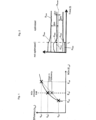
- the proposed method allows these cylinder-specific cylinder parameters to be taken into account by setting a cylinder-specific cylinder setpoint p max ' for a first cylinder signal p max for each cylinder 2 and setting a combustion parameter Q of cylinder 2 (e.g. the amount of fuel supplied to a cylinder) depending on the deviation of the first cylinder signal p max from the cylinder setpoint p max ', whereby the first cylinder signal p max is adjusted to the cylinder setpoint p max ' (see Fig. 2 ).
- a combustion parameter Q of cylinder 2 e.g. the amount of fuel supplied to a cylinder
- the cylinder-specific cylinder target values p max ' of cylinder 2 can be set in such a way that the cylinder-specific NOx emissions E cyl ' or cylinder efficiencies ⁇ cyl ' of all cylinders 2 to be achieved are within a predeterminable range or are essentially the same.
- the cylinder-specific differences in cylinder parameters a higher overall efficiency can be achieved across all cylinders 2 than without such consideration.
- the individual first cylinder signals p max are tracked to the respective cylinder-specific cylinder setpoints p max ' from a point in time t 1 , from which control takes place in accordance with the proposed method.
- the detected cylinder-specific first cylinder signal p max of a cylinder 2 is fed to a control device 7 via a signal line 14, wherein the determination of the maximum internal cylinder pressure p max over one combustion cycle or the temporal filtering of the maximum internal cylinder pressure p max over several combustion cycles can also be carried out by the control device 7.
- control device 7 determines a fuel quantity Q to be metered individually for each cylinder as a combustion parameter for the cylinders 2 according to the proposed method and reports this to the corresponding fuel metering valves 3 via control lines 15.
- the corresponding cylinder-specific fuel quantities Q are metered into the cylinders 2 by the fuel metering valves 3 and thus the cylinder-specific first cylinder signals p max are adjusted according to the proposed method to the cylinder-specific cylinder setpoint values p max ' formed by the control device 7.
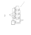
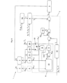
- Fig. 4 shows a schematic block diagram of three cylinders 2 of an internal combustion engine 1 with an air-guided combustion process.
- Each cylinder 2 is assigned a fuel metering valve 3, whereby the fuel quantity Q supplied to the corresponding cylinder 2 can be adjusted by the respective fuel metering valve 3.
- a control device 7 controls the fuel metering valves 3 in that the control device 7 outputs a respective cylinder-specific opening duration of the fuel metering valve 3 in the form of a cylinder-specific parameter value t cyl .
- the fuel metering valves 3 are designed as port injection valves, which only have a fully open and a fully closed position.
- a fuel metering valve 3 When a fuel metering valve 3 is fully open, a fuel in the form of a propellant gas is injected into the inlet tract of the cylinder 2 assigned to the fuel metering valve 3.
- the fuel quantity Q for the respective cylinder 2 can thus be determined by the opening duration of the fuel metering valve 3.
- a cylinder-specific first cylinder signal p max is recorded from each cylinder 2 and fed to the control device 7.
- a cylinder-specific first cylinder signal p max corresponds to the maximum internal cylinder pressure of the corresponding cylinder 2 during a combustion cycle.
- the cylinder-specific first cylinder signals p max are fed to a difference value calculation 8 of the control device 7.
- the difference value calculation 8 determines a difference value ⁇ t cyl for each cylinder 2 or for each fuel metering valve 3, which is added to a predefinable target value t g , resulting in a cylinder-specific opening duration for each fuel metering valve 3 as the parameter value t cyl .
- the predeterminable global engine target value t g is determined from a predeterminable fuel-air ratio ⁇ , whereby the predeterminable fuel-air ratio ⁇ is determined by an emissions controller 5a from a power equivalent P of the output power of the internal combustion engine 1 (e.g. a measured electrical power of a generator connected to the internal combustion engine 1) and/or from a charge air pressure p A and/or from an engine speed n of the internal combustion engine 1.
- the pressure p A and the temperature T A of the charge air, the pressure p G and the temperature T G of the fuel supply as well as the engine speed n of the internal combustion engine 1 can also be included in a target value calculation 6.
- a flow characteristic value of the fuel metering valves 3 e.g. effective flow diameter according to the polytropic outflow equation or a Kv value
- characteristics of the fuel or fuel gas e.g. the gas density, the polytropic exponent or the calorific value
- the target value calculation 6 determines the predeterminable target value t g, which corresponds to an engine-global opening duration base value for the opening durations of all fuel metering valves 3.
- the difference value calculation 8 determines a cylinder-specific opening duration offset or difference value ⁇ t cyl for each individual fuel metering valve 3. These cylinder-specific difference values ⁇ t cyl depend on the deviation of the cylinder peak pressure p max of the respective cylinder 2 from the respective cylinder-specific cylinder target value p max '. The respective sum of the engine-global opening duration base value t g and the cylinder-specific opening duration offset ⁇ t cyl results in the target opening duration t cyl commanded to the driver electronics of the respective fuel metering valve 3.
- corresponding cylinder-specific opening duration offsets ⁇ t cyl can be calculated from the deviations of the cylinder-specific cylinder exhaust gas temperatures T E from a respective cylinder-specific cylinder setpoint for the cylinder exhaust gas temperature.
- the cylinder-specific cylinder exhaust gas temperatures T E can be used, for example, as an alternative if no cylinder internal pressure sensors 4 are installed or as a fallback solution if cylinder pressure signals fail in order to increase the availability of the internal combustion engine 1 in the event of a cylinder pressure sensor failure.
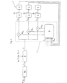
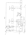
- Fig. 5 shows a block diagram according to Fig. 4 , in this case the internal combustion engine 1 is operated with a gas-based combustion process.
- the predeterminable global engine target value t g is determined by a controller 5b, which can comprise a power controller and/or a speed controller.
- a predeterminable target power equivalent Ps (nominal power) of the internal combustion engine 1 can serve as input variables for the power controller, and for the speed controller, in addition to a current engine speed n (actual speed) of the internal combustion engine 1, a predeterminable target speed ns (nominal speed) of the internal combustion engine 1 can serve as input variables.
- an engine-global preset value for the fuel mass flow m is determined, from which the predefinable engine-global target value t g - e.g. for the engine-global opening duration of fuel metering valves or for the engine-global preset value for the ignition timing of ignition devices - is subsequently determined in a target value calculation 6.
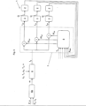
- Fig. 6 shows a block diagram according to Fig. 4 , wherein the control device 7 and the difference value calculation 8 are shown in more detail. This illustration shows the control sequence for only one cylinder 2 of the internal combustion engine 1 in detail. Other cylinders 2 of the internal combustion engine 1 are indicated by dashed lines.
- An internal cylinder pressure sensor 4 is arranged in each cylinder 2.
- An internal cylinder pressure sensor 4 can record the course of the internal cylinder pressure p cyl over a combustion cycle.
- a maximum value detection device 9 can determine the maximum internal cylinder pressure p max or peak pressure of the respective cylinder 2 in the previous combustion cycle.
- the peak pressures of all cylinders 2 are fed as cylinder-specific first cylinder signals p max to a mean value calculation 10.
- this mean value calculation 10 forms the arithmetic mean p mean from the cylinder-specific first cylinder signals p max and outputs this.
- a cylinder-specific offset ⁇ m is calculated and output in an offset calculation 18.
- the sum of the arithmetic mean p mean of the cylinder-specific first cylinder signals p max of all cylinders 2 and the cylinder-specific offset ⁇ m forms the cylinder-specific cylinder setpoint p max ', which is fed to a setpoint controller 11.
- the cylinder-specific offset ⁇ m is calculated in an offset calculation 18 from the cylinder internal pressure in the corresponding cylinder 2 before ignition p cyl ' (after closing an intake valve assigned to cylinder 2 during the compression stroke) and from the combustion center of cylinder 2.
- the cylinder internal pressure before ignition p cyl ' can either be determined directly from the temporal progression of the cylinder internal pressure signal p cyl by means of a corresponding pressure calculation 19 or can also be calculated from a load-dependent pressure determination map 20.
- the pressure determination map 20 can contain corresponding values of the cylinder internal pressure before ignition p cyl ', which are dependent on the load and/or the charge air pressure p A and/or the charge air temperature T A and/or the engine speed n of the internal combustion engine 1.
- the source for the value of the cylinder internal pressure before ignition p cyl ' is selected by a pressure source switch 22.
- the combustion center of gravity of the respective cylinder 2 is determined in a center of gravity determination 21 in a known manner from the temporal progression of the cylinder internal pressure signal p cyl .
- the cylinder-specific offset ⁇ m can be determined depending on at least one of the following cylinder-specific cylinder parameters: air mass equivalent, combustion center of gravity, compression ratio, ignition delay.
- the cylinder-specific offset ⁇ m can be determined based on deviations of at least one respective cylinder parameter from the mean value of this cylinder parameter across all cylinders 2.
- the deviation of the first cylinder signal p max of a cylinder 2 from the corresponding cylinder setpoint p max ' is determined and subsequently a difference value ⁇ t cyl is determined for the fuel metering valve 3 assigned to the cylinder 2.
- the respective difference value ⁇ t cyl for a fuel metering valve 3, which is assigned to the respective cylinder 2, is added to a global engine, predeterminable target value t g , which results in an opening duration for the fuel metering valve 3 as a parameter value t cyl .
- the predeterminable target value t g is, as in Fig. 4 described, from an emission controller of the internal combustion engine 1. In principle, it can also be determined from a power controller and/or from a speed controller (as in Fig. 5 described) of the internal combustion engine 1.
- the respective difference value ⁇ t cyl includes a cylinder-specific pilot control value t p , which is determined by a pilot control value calculation 12 from the charge air pressure p A and/or the charge air temperature T A and/or the engine speed n of the internal combustion engine 1.
- This respective pilot control value t p can be determined, for example, by measurements when starting up the internal combustion engine 1 and stored in a characteristic map.
- the setpoint controller 11 can be designed as a P, PI or PID controller, for example.
- controller concepts and controller types can also be used, such as LQ controllers, robust controllers or fuzzy controllers.
- the difference values ⁇ t cyl are each additionally subjected to a compensation value t o from a compensation value calculation 13.
- This compensation value t o which is the same for all difference values ⁇ t cyl , corresponds to the arithmetic mean of the difference values ⁇ t cyl of all cylinders 2 and can be positive or negative.
- Fig. 7 shows a schematic block diagram similar to the Fig. 4 , however, with the embodiment of the invention shown, it is not the fuel quantities Q for the cylinders 2 that are set, but rather the ignition points Z of ignition devices 23 arranged on or in the cylinders 2.
- the globally predeterminable target value t g (global default value) for the ignition point Z is determined from an ignition point map 16, with suitable values for the global default value t g depending on the power or power equivalent P and/or the charge air pressure p A and/or the charge air temperature T A and/or the engine speed n of the internal combustion engine 1 being stored in the ignition point map 16.
- the respective parameter value t cyl determined by the control device 7 - expressed as degrees of crank angle before TDC - is reported to an ignition control 17.
- the ignition control 17 activates the respective ignition device 23 at the respectively specified ignition point Z.
- the ignition point Z of a cylinder 2 is set earlier than the global specified value t g if the cylinder peak pressure p max of cylinder 2 (first cylinder signal) is less than the cylinder target value p max ' and the ignition point Z of a cylinder 2 is set later than the global specified value t g if the cylinder peak pressure p max of cylinder 2 is greater than the cylinder target value p max '.
- Fig. 8 shows a schematic block diagram of another embodiment of the invention similar to the Fig. 6 , however, it is not the fuel quantities Q for the cylinders 2 that are set, but the ignition times Z of ignition devices 23 arranged on or in the cylinders 2.
- the nitrogen oxide emissions E cyl of a cylinder 2 are recorded over a combustion cycle by a NOx sensor 24 and fed to an evaluation unit 25.
- the evaluation unit 25 determines a filtered emission value from the time course of the nitrogen oxide emissions E cyl over a combustion cycle, which is fed to the setpoint calculation 10 as a cylinder-specific signal E. From the cylinder-specific signals E of all cylinders 2, the setpoint calculation 10 forms the median E median and outputs it.
- a cylinder-specific offset ⁇ m is calculated and output in an offset calculation 18.
- the sum of the median E median and the cylinder-specific offset ⁇ m forms the cylinder-specific cylinder setpoint E', which is reported to a setpoint controller 11.
- the cylinder-specific offset ⁇ m is determined in an offset calculation 18 by reading out a difference value map 26 in which suitable values of the offsets ⁇ m for the corresponding cylinder 2 are stored depending on the power P and/or the charge air pressure p A and/or the charge air temperature T A and/or the engine speed n of the internal combustion engine 1.
- the values stored in the difference value map 26 for the cylinder-specific offsets ⁇ m of the cylinders 2 were determined on a test bench.
Landscapes
- Engineering & Computer Science (AREA)
- Chemical & Material Sciences (AREA)
- Combustion & Propulsion (AREA)
- Mechanical Engineering (AREA)
- General Engineering & Computer Science (AREA)
- Chemical Kinetics & Catalysis (AREA)
- General Chemical & Material Sciences (AREA)
- Oil, Petroleum & Natural Gas (AREA)
- Combined Controls Of Internal Combustion Engines (AREA)
- Electrical Control Of Air Or Fuel Supplied To Internal-Combustion Engine (AREA)
- Electrical Control Of Ignition Timing (AREA)
- Output Control And Ontrol Of Special Type Engine (AREA)
Claims (14)
- Procédé destiné à faire fonctionner un moteur à combustion interne (1), en particulier un moteur à gaz, avec au moins deux cylindres (2), dans lequel pour chaque cylindre (2), un premier signal de cylindre (pmax, E) spécifique au cylindre est détecté, dans lequel au moins un paramètre de combustion (Q, Z) du cylindre (2) correspondant est réglé en fonction du premier signal de cylindre (Pmax, E), dans lequel pour chaque cylindre (2), une valeur théorique de cylindre (pmax', E') spécifique au cylindre pour le premier signal de cylindre (pmax, E) est réglée, laquelle valeur théorique de cylindre (pmax', E') spécifique au cylindre comprend une grandeur statistique des premiers signaux de cylindre (pmax, E) de tous les cylindres (2) et un décalage (Δm) spécifique au cylindre, dans lequel l'au moins un paramètre de combustion (Q, Z) du cylindre (2) est réglé en fonction de l'écart du premier signal de cylindre (pmax, E) par rapport à la valeur théorique de cylindre (pmax', E'), dans lequel le premier signal de cylindre (pmax, E) est mis à jour selon la valeur théorique de cylindre (pmax', E'), caractérisé en ce que le décalage (Δm) spécifique au cylindre- est déterminé par un champ caractéristique de valeurs différentielles (20, 26), dans lequel au moins un équivalent de puissance (P) de la puissance délivrée du moteur à combustion interne (1) et/ou une pression d'air de suralimentation (pA) du moteur à combustion interne (1) sont pris en compte dans le champ caractéristique de valeurs différentielles (20, 26), et- est déterminé en fonction d'au moins un des paramètres de cylindre spécifiques au cylindre suivants : pression de cylindre pendant la phase de compression avant l'allumage, équivalent de masse d'air, position de gravité de combustion, rapport de compression, retard d'allumage.
- Procédé selon la revendication 1, caractérisé en ce que pour chaque cylindre (2), au moins un des premiers signaux de cylindre spécifiques au cylindre suivants est détecté : pression interne de cylindre (pcyl), température de gaz d'échappement de cylindre (TE), émissions d'oxyde d'azote (E), dans lequel une pression interne de cylindre maximale (pmax) d'un cycle de combustion est détectée de préférence en tant que premier signal de cylindre spécifique au cylindre.
- Procédé selon la revendication 1 ou 2, caractérisé en ce que la valeur théorique de cylindre (pmax', E') spécifique au cylindre représente la valeur moyenne arithmétique (pmean) et/ou la médiane (Emedian) des premiers signaux de cylindre (pmax, E) de tous les cylindres (2).
- Procédé selon l'une quelconque des revendications 1 à 3, caractérisé en ce que sont prises en compte en supplément dans le champ caractéristique de valeurs différentielles (26) une température d'air de suralimentation (TA) et/ou une vitesse de rotation de moteur (n) du moteur à combustion interne (1).
- Procédé selon l'une quelconque des revendications 1 à 4, caractérisé en ce que le décalage (Δm) spécifique au cylindre est déterminé en fonction d'au moins un écart (Δpverd, Δair, ΔMFB, Δε, Δdelay) d'un paramètre de cylindre par rapport à une valeur moyenne du paramètre de cylindre de tous les cylindres.
- Procédé selon la revendication 5, caractérisé en ce que le décalage (Δm) spécifique au cylindre est déterminé à partir d'au moins un écart (Δpverd, Δair, ΔMFB, Δε, Δdelay) selon la formule suivante :

- Procédé selon l'une quelconque des revendications 1 à 6, caractérisé en ce qu'une quantité de combustible (Q) pour le cylindre (2) correspondant est réglée en tant que paramètre de combustion, dans lequel de préférence la quantité de combustible (Q) pour un cylindre (2) est augmentée si le premier signal de cylindre (pmax, E) spécifique au cylindre est inférieur à la valeur théorique de cylindre (pmax', E') spécifique au cylindre et/ou la quantité de combustible (Q) pour un cylindre (2) est réduite si le premier signal de cylindre (pmax, E) spécifique au cylindre est supérieur à la valeur théorique de cylindre (pmax', E') spécifique au cylindre.
- Procédé selon la revendication 7, caractérisé en ce qu'est prévue pour chaque cylindre (2) une soupape de dosage de combustible (3), dans lequel la durée d'ouverture (tcyl) de la soupape de dosage de combustible (3) correspondante est réglée pour régler la quantité de combustible (Q) pour un cylindre (2) .
- Procédé selon l'une quelconque des revendications 1 à 8, caractérisé en ce qu'un moment d'allumage (Z) pour le cylindre (2) correspondant est réglé en tant que paramètre de combustion, dans lequel de préférence le moment de combustion (Z) pour un cylindre (2) est réglé plus tôt si le premier signal de cylindre (pmax, E) spécifique au cylindre est inférieur à la valeur théorique de cylindre (pmax', E') spécifique au cylindre et/ou le moment d'allumage (Z) pour un cylindre (2) est réglé plus tard si le premier signal de cylindre (pmax, E) spécifique au cylindre est supérieur à la valeur théorique de cylindre (pmax', E') spécifique au cylindre.
- Procédé selon la revendication 9, caractérisé en ce qu'est prévu pour chaque cylindre (2) un système d'allumage (18), dans lequel le moment d'allumage (Z) du système d'allumage (18) est réglé en degrés d'angle de vilebrequin avant le PMH (tcyl).
- Procédé selon l'une quelconque des revendications 1 à 10, caractérisé en ce que pour régler l'au moins un paramètre de combustion (Q, Z), une valeur de paramètre (tcyl) est déterminée, dans lequel de préférence la valeur de paramètre (tcyl) comprend une valeur cible (tg) globale moteur pouvant être spécifiée.
- Procédé selon la revendication 11, caractérisé en ce que la valeur cible (tg) pouvant être spécifiée est déterminée à partir d'un rapport combustible-air (λ) pouvant être spécifié, dans lequel de préférence le rapport combustible-air (λ) pouvant être spécifié est déterminé à partir d'un équivalent de puissance (P) de la puissance délivrée du moteur à combustion interne (1), de préférence d'une puissance électrique d'un générateur raccordé au moteur à combustion interne (1), et/ou à partir d'une pression d'air de suralimentation (pA) et/ou à partir d'une vitesse de rotation de moteur (n) du moteur à combustion interne (1).
- Procédé selon la revendication 11, caractérisé en ce que la valeur cible (tg) pouvant être spécifiée est déterminée en fonction de l'écart d'un équivalent de puissance (P) de la puissance délivrée du moteur à combustion interne (1), d'un équivalent de puissance cible (Ps) pouvant être spécifié et/ou en fonction de l'écart d'une vitesse de rotation de moteur (n) du moteur à combustion interne (1) par une vitesse de rotation cible (ns) pouvant être spécifiée du moteur à combustion interne (1).
- Procédé selon l'une quelconque des revendications 1 à 13, caractérisé en ce que pour chaque cylindre (2), un état de combustion est surveillé et est évalué comme étant normal ou anormal en ce qui concerne un état théorique pouvant être spécifié, dans lequel le paramètre de combustion (Q, Z) d'un cylindre (2) est réglé seulement si l'état de combustion du cylindre (2) est évalué comme étant normal, dans lequel de préférence le cognement et/ou l'allumage à incandescence et/ou les ratés dans la combustion sont surveillés comme état de combustion, dans lequel l'état de combustion d'un cylindre (2) est évalué comme étant normal si aucun cognement et/ou aucun allumage à incandescence et/ou aucun raté d'allumage dans la combustion ne peuvent être identifiés.
Applications Claiming Priority (1)
| Application Number | Priority Date | Filing Date | Title |
|---|---|---|---|
| ATA895/2012A AT513359B1 (de) | 2012-08-17 | 2012-08-17 | Verfahren zum Betreiben einer Brennkraftmaschine |
Publications (3)
| Publication Number | Publication Date |
|---|---|
| EP2698521A1 EP2698521A1 (fr) | 2014-02-19 |
| EP2698521C0 EP2698521C0 (fr) | 2025-01-08 |
| EP2698521B1 true EP2698521B1 (fr) | 2025-01-08 |
Family
ID=48876985
Family Applications (1)
| Application Number | Title | Priority Date | Filing Date |
|---|---|---|---|
| EP13003563.7A Active EP2698521B1 (fr) | 2012-08-17 | 2013-07-16 | Procédé destiné au fonctionnement d'un moteur à combustion interne |
Country Status (7)
| Country | Link |
|---|---|
| US (1) | US10066565B2 (fr) |
| EP (1) | EP2698521B1 (fr) |
| JP (1) | JP6262957B2 (fr) |
| KR (2) | KR20140023239A (fr) |
| CN (1) | CN103590911B (fr) |
| AT (1) | AT513359B1 (fr) |
| BR (1) | BR102013020926B1 (fr) |
Families Citing this family (18)
| Publication number | Priority date | Publication date | Assignee | Title |
|---|---|---|---|---|
| AT515499B1 (de) | 2014-02-20 | 2016-01-15 | Ge Jenbacher Gmbh & Co Og | Verfahren zum Betreiben einer Brennkraftmaschine |
| DE102014005986B4 (de) * | 2014-04-25 | 2018-06-14 | Mtu Friedrichshafen Gmbh | Betriebsverfahren für einen Magergasmotor und Magergasmotor |
| AT515769A3 (de) * | 2014-05-09 | 2018-01-15 | Ge Jenbacher Gmbh & Co Og | Verbrennungsmotor und Verfahren zum Betrieb desselben |
| DE102014007009B4 (de) * | 2014-05-13 | 2018-01-18 | Mtu Friedrichshafen Gmbh | Motorüberwachung mittels zylinderindividueller Drucksensoren vorzüglich bei Magergasmotoren mit gespülter Vorkammer |
| DE102014010447A1 (de) * | 2014-07-14 | 2015-07-23 | Mtu Friedrichshafen Gmbh | Verfahren zur Betriebsbereichserweiterung einer Brennkraftmaschine |
| DE102014222474A1 (de) * | 2014-11-04 | 2016-05-04 | Bayerische Motoren Werke Aktiengesellschaft | Anpassung der Fluidmenge des Systems zur Zusatzeinspritzung eines Verbrennungsmotors an das Signal der Klopfregelung |
| US20160160776A1 (en) * | 2014-12-08 | 2016-06-09 | Caterpillar Inc. | Engine System and Method |
| US9441561B2 (en) * | 2014-12-11 | 2016-09-13 | Caterpillar Inc. | System and method for increasing tolerance to fuel variation |
| CN106150719B (zh) * | 2015-04-28 | 2019-05-31 | 长城汽车股份有限公司 | 发动机的控制方法、系统及车辆 |
| AT517206B1 (de) * | 2015-06-30 | 2016-12-15 | Ge Jenbacher Gmbh & Co Og | Verfahren zur Regelung einer Brennkraftmaschine |
| EP3165748A1 (fr) * | 2015-11-04 | 2017-05-10 | GE Jenbacher GmbH & Co. OG | Moteur à combustion interne avec pilotage de quantité d'injection |
| EP3336335B1 (fr) * | 2016-12-15 | 2021-01-27 | Caterpillar Motoren GmbH & Co. KG | Procédé de fonctionnement d'un moteur à combustion interne à combustible gazeux |
| KR102506940B1 (ko) * | 2018-09-28 | 2023-03-07 | 현대자동차 주식회사 | 녹스 발생량 예측 및 제어 방법 |
| US10544749B1 (en) * | 2018-10-11 | 2020-01-28 | Delphi Technologies Ip Limited | Internal combustion engine control method |
| US10634086B1 (en) | 2018-12-20 | 2020-04-28 | Ford Global Technologies, Llc | System and method for estimating cylinder pressures |
| JP7329488B2 (ja) * | 2019-11-15 | 2023-08-18 | エムエーエヌ・エナジー・ソリューションズ・フィリアル・アフ・エムエーエヌ・エナジー・ソリューションズ・エスイー・ティスクランド | クロスヘッド式大型低速ターボ過給2ストロークユニフロー掃気内燃機関及びこれを動作させる方法 |
| DE102024102869B3 (de) * | 2024-02-01 | 2025-07-10 | Man Energy Solutions Se | Verfahren und Steuergerät zum Betreiben einer Brennkraftmaschine |
| US12577918B2 (en) | 2024-07-19 | 2026-03-17 | Caterpillar Inc. | Asymmetric fuel injection window and fuel metering window |
Family Cites Families (76)
| Publication number | Priority date | Publication date | Assignee | Title |
|---|---|---|---|---|
| AT384279B (de) | 1986-03-05 | 1987-10-27 | Jenbacher Werke Ag | Einrichtung zur regelung des verbrennungsluftverh|ltnisses bei einem gasmotor mit magerer betriebsweise |
| JPH04101044A (ja) * | 1990-08-13 | 1992-04-02 | Japan Electron Control Syst Co Ltd | 多気筒内燃機関の燃料供給制御装置 |
| JPH08312433A (ja) * | 1995-05-16 | 1996-11-26 | Mitsubishi Motors Corp | 筒内噴射型火花点火式内燃エンジンの制御装置 |
| JP3152106B2 (ja) * | 1995-05-16 | 2001-04-03 | 三菱自動車工業株式会社 | 筒内噴射型火花点火式内燃エンジンの制御装置 |
| JP2000018075A (ja) * | 1998-07-02 | 2000-01-18 | Nissan Motor Co Ltd | ディーゼルエンジンの燃料噴射制御装置 |
| DE19955252C2 (de) * | 1999-11-17 | 2002-11-07 | Daimler Chrysler Ag | Verfahren und Vorrichtung zur Regelung des Kraftstoff/Luftverhältnisses einer Otto-Brennkraftmaschine |
| JP3679974B2 (ja) * | 2000-05-19 | 2005-08-03 | 株式会社クボタ | 燃料切換型エンジン |
| JP4326131B2 (ja) * | 2000-08-18 | 2009-09-02 | ヤンマー株式会社 | ガス機関の制御装置及び制御方法 |
| JP3913986B2 (ja) * | 2001-01-09 | 2007-05-09 | 三菱電機株式会社 | 内燃機関の空燃比制御装置 |
| DE10110500A1 (de) * | 2001-02-28 | 2002-10-02 | Volkswagen Ag | Verfahren zur Temperatursteuerung eines Katalysatorsystems |
| JP3980424B2 (ja) * | 2002-07-03 | 2007-09-26 | 本田技研工業株式会社 | 内燃機関の空燃比制御装置 |
| US7690352B2 (en) * | 2002-11-01 | 2010-04-06 | Visteon Global Technologies, Inc. | System and method of selecting data content of ionization signal |
| US7021287B2 (en) * | 2002-11-01 | 2006-04-04 | Visteon Global Technologies, Inc. | Closed-loop individual cylinder A/F ratio balancing |
| US7104043B2 (en) * | 2002-11-01 | 2006-09-12 | Visteon Global Technologies, Inc. | Closed loop cold start retard spark control using ionization feedback |
| US7472687B2 (en) * | 2002-11-01 | 2009-01-06 | Visteon Global Technologies, Inc. | System and method for pre-processing ionization signal to include enhanced knock information |
| US7137382B2 (en) * | 2002-11-01 | 2006-11-21 | Visteon Global Technologies, Inc. | Optimal wide open throttle air/fuel ratio control |
| US7086382B2 (en) * | 2002-11-01 | 2006-08-08 | Visteon Global Technologies, Inc. | Robust multi-criteria MBT timing estimation using ionization signal |
| US7013871B2 (en) * | 2002-11-01 | 2006-03-21 | Visteon Global Technologies, Inc. | Closed loop MBT timing control using ionization feedback |
| US7134423B2 (en) * | 2002-11-01 | 2006-11-14 | Visteon Global Technologies, Inc. | Ignition diagnosis and combustion feedback control system using an ionization signal |
| JP3991992B2 (ja) * | 2003-09-30 | 2007-10-17 | トヨタ自動車株式会社 | 内燃機関の制御装置 |
| DE10358988B3 (de) * | 2003-12-16 | 2005-05-04 | Siemens Ag | Vorrichtung zum Steuern einer Brennkraftmaschine |
| DE102005003009A1 (de) * | 2004-01-23 | 2005-09-01 | Denso Corp., Kariya | Vorrichtung zum Schätzen von Luftkraftstoffverhältnissen und Vorrichtung zum Steuern von Luftkraftstoffverhältnissen einzelner Zylinder bei einer Brennkraftmaschine |
| DE102004004291B3 (de) * | 2004-01-28 | 2005-01-27 | Siemens Ag | Verfahren zum Anpassen des Erfassens eines Messsignals einer Abgassonde |
| JP2005240712A (ja) * | 2004-02-27 | 2005-09-08 | Mitsubishi Heavy Ind Ltd | ガスエンジン |
| US7021276B2 (en) * | 2004-03-25 | 2006-04-04 | International Engine Intellectual Property Company, Llc | Control strategy for HCCI-CD combustion in a diesel engine using two fuel injection phases |
| JP4281610B2 (ja) * | 2004-04-27 | 2009-06-17 | 株式会社豊田自動織機 | 予混合圧縮自着火機関の運転方法及び予混合圧縮自着火機関 |
| DE102004032986A1 (de) | 2004-07-08 | 2006-02-09 | Daimlerchrysler Ag | Verfahren zur Regelung des Kompressionszündbetriebes einer Brennkraftmaschine |
| JP4439345B2 (ja) * | 2004-07-14 | 2010-03-24 | 本田技研工業株式会社 | 内燃機関の制御装置 |
| DE102004043529B3 (de) * | 2004-09-08 | 2005-09-01 | Siemens Ag | Verfahren zur Gemischregelung einer Otto-Mehrzylinder-Brennkraftmaschine mit zylinderbezogenen Einzelkatalysatoren und einem den Einzelkatalysatoren nachgeschalteten gemeinsamen Hauptkatalysator |
| DE102004046083B4 (de) * | 2004-09-23 | 2016-03-17 | Robert Bosch Gmbh | Verfahren und Vorrichtung zur Steuerung einer Brennkraftmaschine |
| DE102004048330B4 (de) * | 2004-10-05 | 2014-10-16 | Volkswagen Ag | Verfahren zur Diagnose für eine Motorsteuerung und entsprechende Motorsteuerung |
| DE112005003527B4 (de) * | 2005-04-01 | 2020-08-06 | Hoerbiger Wien Gmbh | Verfahren für die Schätzung von Verbrennungsparametern |
| JP4243598B2 (ja) * | 2005-08-25 | 2009-03-25 | 本田技研工業株式会社 | 内燃機関の制御装置 |
| JP2007023973A (ja) * | 2005-07-20 | 2007-02-01 | Honda Motor Co Ltd | 内燃機関の制御装置 |
| DE102005034690B3 (de) * | 2005-07-25 | 2007-01-04 | Siemens Ag | Verfahren und Vorrichtung zum Anpassen des Erfassens eines Messsignals einer Abgassonde |
| JP4605038B2 (ja) * | 2006-02-02 | 2011-01-05 | 株式会社デンソー | 燃料噴射装置 |
| JP2007231883A (ja) * | 2006-03-02 | 2007-09-13 | Toyota Motor Corp | 内燃機関の空燃比制御装置 |
| DE102006011723B3 (de) * | 2006-03-14 | 2007-08-23 | Siemens Ag | Adaptionsverfahren für Streuungen in zylinderselektiven Einspritzmengen einer Direkteinspritzanlage und Verfahren zur zylinderselektiven Einspritzsteuerung |
| JP4673787B2 (ja) * | 2006-05-10 | 2011-04-20 | 本田技研工業株式会社 | 内燃機関の空燃比制御装置 |
| JP4639166B2 (ja) * | 2006-05-18 | 2011-02-23 | 本田技研工業株式会社 | 制御装置 |
| US7448359B2 (en) * | 2006-08-10 | 2008-11-11 | Ford Global Technologies, Llc | Multi-mode internal combustion engine |
| DE102006037752B3 (de) * | 2006-08-11 | 2007-04-19 | Siemens Ag | Verfahren und Vorrichtung zum Betreiben einer Brennkraftmaschine |
| US7748355B2 (en) * | 2006-09-15 | 2010-07-06 | Ford Global Technologies, Llc | Approach for facilitating engine mode transitions |
| US7506535B2 (en) * | 2007-04-24 | 2009-03-24 | Gm Global Technology Operations, Inc. | Method and apparatus for determining a combustion parameter for an internal combustion engine |
| US7689343B2 (en) * | 2007-04-24 | 2010-03-30 | Gm Global Technology Operations, Inc. | Method and apparatus for enabling control of fuel injection for an engine operating in an auto-ignition mode |
| DE102007027483A1 (de) * | 2007-06-14 | 2008-12-18 | Robert Bosch Gmbh | Verfahren zur Ermittlung eines Qualitätsmerkmals eines Dieselkraftstoffes |
| JP4478708B2 (ja) * | 2007-09-20 | 2010-06-09 | ダイハツディーゼル株式会社 | エンジンの制御装置 |
| JP4858397B2 (ja) * | 2007-10-15 | 2012-01-18 | 株式会社豊田自動織機 | 予混合圧縮着火機関 |
| DE102007050302A1 (de) * | 2007-10-22 | 2009-04-23 | Robert Bosch Gmbh | Verfahren und Vorrichtung zum Ermitteln eines Zylinderdruckmerkmals |
| DE102008004361A1 (de) | 2008-01-15 | 2009-07-16 | Robert Bosch Gmbh | Verfahren zur Regelung eines Verbrennungsmotors, Computerprogramm und Steuergerät |
| DE102008005524A1 (de) * | 2008-01-22 | 2009-07-23 | Robert Bosch Gmbh | Verfahren zum Steuern eines selbstzündenden Verbrennungsmotors und Steuervorrichtung zum Steuern eines selbstzündenden Verbrennungsmotors |
| FI121030B (fi) * | 2008-03-31 | 2010-06-15 | Waertsilae Finland Oy | Pilottipolttoaineen syötön säätöjärjestelmä ja menetelmä polttomoottorille |
| FI121031B (fi) | 2008-03-31 | 2010-06-15 | Waertsilae Finland Oy | Säätöjärjestelmä ja menetelmä kaasua käyttävän polttomoottorin sylinterien tasapainottamiseksi |
| DE102008020185B4 (de) * | 2008-04-22 | 2015-03-12 | Continental Automotive Gmbh | Verfahren und Vorrichtung zum Steuern einer Brennkraftmaschine mit Stopp-Start-Automatik |
| DE102008001668A1 (de) * | 2008-05-08 | 2009-11-12 | Robert Bosch Gmbh | Verfahren und Vorrichtung zur Bestimmung der Zusammensetzung eines Kraftstoffgemischs |
| JP2010001745A (ja) | 2008-06-18 | 2010-01-07 | Hitachi Automotive Systems Ltd | 火花点火式多気筒エンジンの燃焼制御装置 |
| EP2136058A1 (fr) * | 2008-06-19 | 2009-12-23 | Continental Automotive GmbH | Adaptation de masse de carburant minimum utilisant un détecteur de pression de cylindre |
| FR2936019B1 (fr) * | 2008-09-18 | 2010-09-10 | Inst Francais Du Petrole | Procede de detection de combustion anormale pour moteurs a combustion interne |
| JP4772846B2 (ja) * | 2008-10-01 | 2011-09-14 | 川崎重工業株式会社 | ガスエンジンのノッキング制御装置 |
| US8522750B2 (en) * | 2008-10-02 | 2013-09-03 | Delaware Capital Formation, Inc. | Method and apparatus for automatic pressure balancing of industrial large-bore internal combustion engines |
| JP5066060B2 (ja) * | 2008-11-10 | 2012-11-07 | 本田技研工業株式会社 | 内燃機関の制御装置 |
| US7996142B2 (en) | 2008-11-14 | 2011-08-09 | General Electric Company | System for closed-loop control of combustion in engines |
| DE102008058008B3 (de) * | 2008-11-19 | 2010-02-18 | Continental Automotive Gmbh | Vorrichtung zum Betreiben einer Brennkraftmaschine |
| US8286471B2 (en) * | 2009-01-13 | 2012-10-16 | Ford Global Technologies, Llc | Variable displacement engine diagnostics |
| JP2011069277A (ja) * | 2009-09-25 | 2011-04-07 | Toyota Motor Corp | 内燃機関装置および内燃機関の燃料噴射制御方法並びに車両 |
| US8813690B2 (en) * | 2009-10-30 | 2014-08-26 | Cummins Inc. | Engine control techniques to account for fuel effects |
| DE102010000747A1 (de) | 2010-01-08 | 2011-07-14 | Robert Bosch GmbH, 70469 | Verfahren zum Regeln einer HCCI-Verbrennung in einem Reaktor einer Brennkraftmaschine |
| US20120191325A1 (en) * | 2010-01-13 | 2012-07-26 | GM Global Technology Operations LLC | Injection fuel and load balancing control system |
| JP5018902B2 (ja) * | 2010-01-18 | 2012-09-05 | トヨタ自動車株式会社 | 内燃機関装置および内燃機関の制御方法並びに車両 |
| GB2477122A (en) * | 2010-01-22 | 2011-07-27 | Gm Global Tech Operations Inc | Determining the pressure offset of an in-cylinder pressure sensor of an i.c. engine |
| DE102010030404A1 (de) * | 2010-06-23 | 2011-12-29 | Robert Bosch Gmbh | Verfahren zum Betrieb einer Verbrennungskraftmaschine |
| JP5494317B2 (ja) * | 2010-07-20 | 2014-05-14 | トヨタ自動車株式会社 | 多気筒内燃機関の異常判定装置 |
| DE102010045689A1 (de) * | 2010-09-16 | 2011-04-21 | Daimler Ag | Verfahren zum Betreiben einer Verbrennungskraftmaschine |
| DE102011011337B3 (de) * | 2011-02-16 | 2012-02-16 | Iav Gmbh Ingenieurgesellschaft Auto Und Verkehr | Verfahren zur Zylindergleichstellung einer Mehrzylinder-Verbrennungskraftmaschine |
| US8600648B2 (en) * | 2011-05-02 | 2013-12-03 | Ford Global Technologies, Llc | Method and system for engine speed control |
| AT513139B1 (de) | 2012-08-17 | 2014-02-15 | Ge Jenbacher Gmbh & Co Og | Verfahren zum Betreiben einer Brennkraftmaschine |
-
2012
- 2012-08-17 AT ATA895/2012A patent/AT513359B1/de active
-
2013
- 2013-07-16 EP EP13003563.7A patent/EP2698521B1/fr active Active
- 2013-08-13 JP JP2013168082A patent/JP6262957B2/ja active Active
- 2013-08-14 US US13/966,625 patent/US10066565B2/en active Active
- 2013-08-16 BR BR102013020926-0A patent/BR102013020926B1/pt active IP Right Grant
- 2013-08-16 KR KR1020130097390A patent/KR20140023239A/ko not_active Ceased
- 2013-08-16 CN CN201310357391.8A patent/CN103590911B/zh active Active
-
2017
- 2017-07-24 KR KR1020170093673A patent/KR20170089815A/ko not_active Ceased
Also Published As
| Publication number | Publication date |
|---|---|
| CN103590911B (zh) | 2017-08-29 |
| EP2698521C0 (fr) | 2025-01-08 |
| BR102013020926A2 (pt) | 2015-12-15 |
| US10066565B2 (en) | 2018-09-04 |
| KR20170089815A (ko) | 2017-08-04 |
| EP2698521A1 (fr) | 2014-02-19 |
| US20140052363A1 (en) | 2014-02-20 |
| JP2014037834A (ja) | 2014-02-27 |
| JP6262957B2 (ja) | 2018-01-17 |
| BR102013020926B1 (pt) | 2021-09-28 |
| AT513359B1 (de) | 2014-07-15 |
| KR20140023239A (ko) | 2014-02-26 |
| AT513359A1 (de) | 2014-03-15 |
| CN103590911A (zh) | 2014-02-19 |
Similar Documents
| Publication | Publication Date | Title |
|---|---|---|
| EP2698521B1 (fr) | Procédé destiné au fonctionnement d'un moteur à combustion interne | |
| EP2698520B1 (fr) | Procédé destiné au fonctionnement d'un moteur à combustion interne | |
| DE102009033957B4 (de) | Verfahren zum Steuern des Verbrennungsgeräuschs in einem Motor mit Kompressionszündung | |
| DE112010005548B4 (de) | Verfahren zur bestimmung der agr-rate eines verbrennungsmotors und steuervorrichtung für einen verbrennungsmotor | |
| DE102011100291B4 (de) | Verfahren zum Einstellen einer Kraftstoffeinspritzungszeiteinstellung in einem Verbrennungsmotor | |
| EP2665905B1 (fr) | Procédé pour commander un moteur à combustion interne comprenant au moins deux cylindres | |
| DE112006003029B4 (de) | System und Verfahren zum Steuern des Zylindergleichgewichts für einen Motor unter Anwendung einer zylinderdruckbasierten Mehrgrößenregelung | |
| DE112011105773B4 (de) | Kraftstoffeinspritzsteuervorrichtung für eine Brennkraftmaschine | |
| DE112005003527T5 (de) | Verfahren für die Schätzung von Verbrennungsparametern | |
| EP2910755B1 (fr) | Procédé destiné au fonctionnement d'un moteur à combustion interne | |
| DE102010030032A1 (de) | Verfahren zum Steuern einer Verbrennungskraftmaschine mit mehreren Kraftstoffen und mehreren Kraftstoff-Einspritzventilen | |
| DE102008002261A1 (de) | Verfahren und Vorrichtung zur Ermittlung eines oder mehrerer Brennbeginne in einem Zylinder eines Verbrennungsmotors aus einem bereitgestellten Zylinderdruckverlauf | |
| DE102009008248A1 (de) | Verfahren zur Verhinderung von Vorentflammungen in Zylindern einer ottomotorisch betriebenen Brennkraftmaschine | |
| DE102012208335A1 (de) | Adaptionssteuerung einer Mager-NOx-Fallen-Regeneration mit Biodiesel während eines transienten Motorbetriebes | |
| DE102011102017A1 (de) | Verfahren und Vorrichtung zum Steuern des Betriebs eines in einem HCCI-Verbrennungsmodus arbeitenden Verbrennungsmotors | |
| DE102011102029A1 (de) | Verfahren und vorrichtung zum betreiben eines verbrennungsmotors in einem verbrennungsmodus mit homogener kompressionszündung | |
| DE102015119281A1 (de) | Zündkerzenverschmutzungsdetektion | |
| DE102007030280A1 (de) | Verfahren zum Betrieb einer Brennkraftmaschine | |
| DE60318195T2 (de) | Dieselmotor mit einer vorrichtung zur steuerung des stroms von eingespritztem kraftstoff | |
| DE60209437T2 (de) | Verbrennungskraftmaschine, Verfahren zu deren Betrieb mit Selbstzündung und Computer lesbares Speichermedium | |
| DE102011004068B3 (de) | Verfahren und Steuervorrichtung zum Gleichstellen mehrerer Zylinder einer Brennkraftmaschine | |
| DE102011012100B4 (de) | Verfahren zum Betrieb einer Verbrennungskraftmaschine | |
| DE102014210206A1 (de) | Steuervorrichtung und Steuerverfahren für Innenverbrennungsmotor | |
| EP2029874A1 (fr) | Moteur à combustion interne et procédé de fonctionnement associé | |
| DE102017107552A1 (de) | Verfahren und vorrichtung zur steuerung des betriebes eines verbrennungsmotors |
Legal Events
| Date | Code | Title | Description |
|---|---|---|---|
| AK | Designated contracting states |
Kind code of ref document: A1 Designated state(s): AL AT BE BG CH CY CZ DE DK EE ES FI FR GB GR HR HU IE IS IT LI LT LU LV MC MK MT NL NO PL PT RO RS SE SI SK SM TR |
|
| AX | Request for extension of the european patent |
Extension state: BA ME |
|
| PUAI | Public reference made under article 153(3) epc to a published international application that has entered the european phase |
Free format text: ORIGINAL CODE: 0009012 |
|
| 17P | Request for examination filed |
Effective date: 20140811 |
|
| RBV | Designated contracting states (corrected) |
Designated state(s): AL AT BE BG CH CY CZ DE DK EE ES FI FR GB GR HR HU IE IS IT LI LT LU LV MC MK MT NL NO PL PT RO RS SE SI SK SM TR |
|
| STAA | Information on the status of an ep patent application or granted ep patent |
Free format text: STATUS: EXAMINATION IS IN PROGRESS |
|
| 17Q | First examination report despatched |
Effective date: 20170216 |
|
| RAP1 | Party data changed (applicant data changed or rights of an application transferred) |
Owner name: INNIO JENBACHER GMBH & CO OG |
|
| P01 | Opt-out of the competence of the unified patent court (upc) registered |
Effective date: 20230614 |
|
| GRAP | Despatch of communication of intention to grant a patent |
Free format text: ORIGINAL CODE: EPIDOSNIGR1 |
|
| STAA | Information on the status of an ep patent application or granted ep patent |
Free format text: STATUS: GRANT OF PATENT IS INTENDED |
|
| RIC1 | Information provided on ipc code assigned before grant |
Ipc: F02D 29/06 20060101ALN20240717BHEP Ipc: F02D 37/02 20060101ALN20240717BHEP Ipc: F02D 41/40 20060101ALN20240717BHEP Ipc: F02M 21/02 20060101ALI20240717BHEP Ipc: F02D 19/02 20060101ALI20240717BHEP Ipc: F02D 35/02 20060101ALI20240717BHEP Ipc: F02D 41/00 20060101AFI20240717BHEP |
|
| RIC1 | Information provided on ipc code assigned before grant |
Ipc: F02D 29/06 20060101ALN20240723BHEP Ipc: F02D 37/02 20060101ALN20240723BHEP Ipc: F02D 41/40 20060101ALN20240723BHEP Ipc: F02M 21/02 20060101ALI20240723BHEP Ipc: F02D 19/02 20060101ALI20240723BHEP Ipc: F02D 35/02 20060101ALI20240723BHEP Ipc: F02D 41/00 20060101AFI20240723BHEP |
|
| RIC1 | Information provided on ipc code assigned before grant |
Ipc: F02D 29/06 20060101ALN20240730BHEP Ipc: F02D 37/02 20060101ALN20240730BHEP Ipc: F02D 41/40 20060101ALN20240730BHEP Ipc: F02M 21/02 20060101ALI20240730BHEP Ipc: F02D 19/02 20060101ALI20240730BHEP Ipc: F02D 35/02 20060101ALI20240730BHEP Ipc: F02D 41/00 20060101AFI20240730BHEP |
|
| INTG | Intention to grant announced |
Effective date: 20240808 |
|
| GRAS | Grant fee paid |
Free format text: ORIGINAL CODE: EPIDOSNIGR3 |
|
| GRAA | (expected) grant |
Free format text: ORIGINAL CODE: 0009210 |
|
| STAA | Information on the status of an ep patent application or granted ep patent |
Free format text: STATUS: THE PATENT HAS BEEN GRANTED |
|
| AK | Designated contracting states |
Kind code of ref document: B1 Designated state(s): AL AT BE BG CH CY CZ DE DK EE ES FI FR GB GR HR HU IE IS IT LI LT LU LV MC MK MT NL NO PL PT RO RS SE SI SK SM TR |
|
| REG | Reference to a national code |
Ref country code: GB Ref legal event code: FG4D Free format text: NOT ENGLISH |
|
| REG | Reference to a national code |
Ref country code: CH Ref legal event code: EP |
|
| REG | Reference to a national code |
Ref country code: DE Ref legal event code: R096 Ref document number: 502013016569 Country of ref document: DE |
|
| REG | Reference to a national code |
Ref country code: IE Ref legal event code: FG4D Free format text: LANGUAGE OF EP DOCUMENT: GERMAN |
|
| U01 | Request for unitary effect filed |
Effective date: 20250120 |
|
| U07 | Unitary effect registered |
Designated state(s): AT BE BG DE DK EE FI FR IT LT LU LV MT NL PT RO SE SI Effective date: 20250127 |
|
| P04 | Withdrawal of opt-out of the competence of the unified patent court (upc) registered |
Free format text: CASE NUMBER: APP_3704/2025 Effective date: 20250122 |
|
| PG25 | Lapsed in a contracting state [announced via postgrant information from national office to epo] |
Ref country code: RS Free format text: LAPSE BECAUSE OF FAILURE TO SUBMIT A TRANSLATION OF THE DESCRIPTION OR TO PAY THE FEE WITHIN THE PRESCRIBED TIME-LIMIT Effective date: 20250408 |
|
| PG25 | Lapsed in a contracting state [announced via postgrant information from national office to epo] |
Ref country code: PL Free format text: LAPSE BECAUSE OF FAILURE TO SUBMIT A TRANSLATION OF THE DESCRIPTION OR TO PAY THE FEE WITHIN THE PRESCRIBED TIME-LIMIT Effective date: 20250108 |
|
| PG25 | Lapsed in a contracting state [announced via postgrant information from national office to epo] |
Ref country code: ES Free format text: LAPSE BECAUSE OF FAILURE TO SUBMIT A TRANSLATION OF THE DESCRIPTION OR TO PAY THE FEE WITHIN THE PRESCRIBED TIME-LIMIT Effective date: 20250108 |
|
| PGFP | Annual fee paid to national office [announced via postgrant information from national office to epo] |
Ref country code: GB Payment date: 20250619 Year of fee payment: 13 |
|
| PG25 | Lapsed in a contracting state [announced via postgrant information from national office to epo] |
Ref country code: NO Free format text: LAPSE BECAUSE OF FAILURE TO SUBMIT A TRANSLATION OF THE DESCRIPTION OR TO PAY THE FEE WITHIN THE PRESCRIBED TIME-LIMIT Effective date: 20250408 Ref country code: IS Free format text: LAPSE BECAUSE OF FAILURE TO SUBMIT A TRANSLATION OF THE DESCRIPTION OR TO PAY THE FEE WITHIN THE PRESCRIBED TIME-LIMIT Effective date: 20250508 |
|
| PG25 | Lapsed in a contracting state [announced via postgrant information from national office to epo] |
Ref country code: HR Free format text: LAPSE BECAUSE OF FAILURE TO SUBMIT A TRANSLATION OF THE DESCRIPTION OR TO PAY THE FEE WITHIN THE PRESCRIBED TIME-LIMIT Effective date: 20250108 |
|
| PG25 | Lapsed in a contracting state [announced via postgrant information from national office to epo] |
Ref country code: GR Free format text: LAPSE BECAUSE OF FAILURE TO SUBMIT A TRANSLATION OF THE DESCRIPTION OR TO PAY THE FEE WITHIN THE PRESCRIBED TIME-LIMIT Effective date: 20250409 |
|
| U20 | Renewal fee for the european patent with unitary effect paid |
Year of fee payment: 13 Effective date: 20250620 |
|
| PG25 | Lapsed in a contracting state [announced via postgrant information from national office to epo] |
Ref country code: SM Free format text: LAPSE BECAUSE OF FAILURE TO SUBMIT A TRANSLATION OF THE DESCRIPTION OR TO PAY THE FEE WITHIN THE PRESCRIBED TIME-LIMIT Effective date: 20250108 |
|
| PG25 | Lapsed in a contracting state [announced via postgrant information from national office to epo] |
Ref country code: CZ Free format text: LAPSE BECAUSE OF FAILURE TO SUBMIT A TRANSLATION OF THE DESCRIPTION OR TO PAY THE FEE WITHIN THE PRESCRIBED TIME-LIMIT Effective date: 20250108 |
|
| PG25 | Lapsed in a contracting state [announced via postgrant information from national office to epo] |
Ref country code: SK Free format text: LAPSE BECAUSE OF FAILURE TO SUBMIT A TRANSLATION OF THE DESCRIPTION OR TO PAY THE FEE WITHIN THE PRESCRIBED TIME-LIMIT Effective date: 20250108 |
|
| PLBE | No opposition filed within time limit |
Free format text: ORIGINAL CODE: 0009261 |
|
| STAA | Information on the status of an ep patent application or granted ep patent |
Free format text: STATUS: NO OPPOSITION FILED WITHIN TIME LIMIT |
|
| REG | Reference to a national code |
Ref country code: CH Ref legal event code: L10 Free format text: ST27 STATUS EVENT CODE: U-0-0-L10-L00 (AS PROVIDED BY THE NATIONAL OFFICE) Effective date: 20251119 |
|
| 26N | No opposition filed |
Effective date: 20251009 |
|
| REG | Reference to a national code |
Ref country code: CH Ref legal event code: H13 Free format text: ST27 STATUS EVENT CODE: U-0-0-H10-H13 (AS PROVIDED BY THE NATIONAL OFFICE) Effective date: 20260224 |
|
| PG25 | Lapsed in a contracting state [announced via postgrant information from national office to epo] |
Ref country code: CH Free format text: LAPSE BECAUSE OF NON-PAYMENT OF DUE FEES Effective date: 20250731 |