EP2698568B1 - Joint d'arbre intermédiaire - Google Patents
Joint d'arbre intermédiaire Download PDFInfo
- Publication number
- EP2698568B1 EP2698568B1 EP13179253.3A EP13179253A EP2698568B1 EP 2698568 B1 EP2698568 B1 EP 2698568B1 EP 13179253 A EP13179253 A EP 13179253A EP 2698568 B1 EP2698568 B1 EP 2698568B1
- Authority
- EP
- European Patent Office
- Prior art keywords
- shaft
- sealing ring
- seal
- sealing
- runners
- Prior art date
- Legal status (The legal status is an assumption and is not a legal conclusion. Google has not performed a legal analysis and makes no representation as to the accuracy of the status listed.)
- Active
Links
Images


Classifications
-
- F—MECHANICAL ENGINEERING; LIGHTING; HEATING; WEAPONS; BLASTING
- F16—ENGINEERING ELEMENTS AND UNITS; GENERAL MEASURES FOR PRODUCING AND MAINTAINING EFFECTIVE FUNCTIONING OF MACHINES OR INSTALLATIONS; THERMAL INSULATION IN GENERAL
- F16J—PISTONS; CYLINDERS; SEALINGS
- F16J15/00—Sealings
- F16J15/16—Sealings between relatively-moving surfaces
- F16J15/26—Sealings between relatively-moving surfaces with stuffing-boxes for rigid sealing rings
- F16J15/30—Sealings between relatively-moving surfaces with stuffing-boxes for rigid sealing rings with sealing rings made of carbon
-
- F—MECHANICAL ENGINEERING; LIGHTING; HEATING; WEAPONS; BLASTING
- F16—ENGINEERING ELEMENTS AND UNITS; GENERAL MEASURES FOR PRODUCING AND MAINTAINING EFFECTIVE FUNCTIONING OF MACHINES OR INSTALLATIONS; THERMAL INSULATION IN GENERAL
- F16J—PISTONS; CYLINDERS; SEALINGS
- F16J15/00—Sealings
- F16J15/16—Sealings between relatively-moving surfaces
- F16J15/26—Sealings between relatively-moving surfaces with stuffing-boxes for rigid sealing rings
-
- F—MECHANICAL ENGINEERING; LIGHTING; HEATING; WEAPONS; BLASTING
- F16—ENGINEERING ELEMENTS AND UNITS; GENERAL MEASURES FOR PRODUCING AND MAINTAINING EFFECTIVE FUNCTIONING OF MACHINES OR INSTALLATIONS; THERMAL INSULATION IN GENERAL
- F16J—PISTONS; CYLINDERS; SEALINGS
- F16J15/00—Sealings
- F16J15/16—Sealings between relatively-moving surfaces
- F16J15/34—Sealings between relatively-moving surfaces with slip-ring pressed against a more or less radial face on one member
- F16J15/3436—Pressing means
- F16J15/3452—Pressing means the pressing force resulting from the action of a spring
-
- F—MECHANICAL ENGINEERING; LIGHTING; HEATING; WEAPONS; BLASTING
- F16—ENGINEERING ELEMENTS AND UNITS; GENERAL MEASURES FOR PRODUCING AND MAINTAINING EFFECTIVE FUNCTIONING OF MACHINES OR INSTALLATIONS; THERMAL INSULATION IN GENERAL
- F16J—PISTONS; CYLINDERS; SEALINGS
- F16J15/00—Sealings
- F16J15/16—Sealings between relatively-moving surfaces
- F16J15/34—Sealings between relatively-moving surfaces with slip-ring pressed against a more or less radial face on one member
- F16J15/3464—Mounting of the seal
-
- F—MECHANICAL ENGINEERING; LIGHTING; HEATING; WEAPONS; BLASTING
- F16—ENGINEERING ELEMENTS AND UNITS; GENERAL MEASURES FOR PRODUCING AND MAINTAINING EFFECTIVE FUNCTIONING OF MACHINES OR INSTALLATIONS; THERMAL INSULATION IN GENERAL
- F16J—PISTONS; CYLINDERS; SEALINGS
- F16J15/00—Sealings
- F16J15/16—Sealings between relatively-moving surfaces
- F16J15/34—Sealings between relatively-moving surfaces with slip-ring pressed against a more or less radial face on one member
- F16J15/3464—Mounting of the seal
- F16J15/348—Pre-assembled seals, e.g. cartridge seals
- F16J15/3484—Tandem seals
-
- F—MECHANICAL ENGINEERING; LIGHTING; HEATING; WEAPONS; BLASTING
- F16—ENGINEERING ELEMENTS AND UNITS; GENERAL MEASURES FOR PRODUCING AND MAINTAINING EFFECTIVE FUNCTIONING OF MACHINES OR INSTALLATIONS; THERMAL INSULATION IN GENERAL
- F16J—PISTONS; CYLINDERS; SEALINGS
- F16J15/00—Sealings
- F16J15/44—Free-space packings
- F16J15/441—Free-space packings with floating ring
Definitions
- the present invention relates to an intershaft seal.
- intershaft seal can be used to seal between relatively rotating coaxial shafts as found e.g. in gas turbine engines.
- One type of intershaft seal is described in EP2420649 , which constitutes the closest prior art document according to the preamble of claim 1 is shown schematically in Figure 1 and is used to seal between gas, liquid or air-gas mixtures.
- the seal is located between inner 37 and outer 38 coaxial shafts and maintains an axial pressure differential between high pressure fluid 31 on a first side of the seal and low pressure fluid 32 on a second side of the seal.
- the shafts rotate relative to each other.
- the seal comprises a carbon ring 35 positioned between first 33 and second 34 runners on respectively the first and second sides of the seal.
- the carbon ring typically has a slight clearance from the outer shaft at cold build conditions.
- the two runners are separated by a spacer 36, so that the axial gap between the runners is slightly longer than the axial length of the carbon ring.
- the carbon ring is pushed by centrifugal forces into more intimate sealing contact with the outer shaft and rotates with that shaft.
- First 39 and second 40 annular sealing interfaces are created between the runners and the axially spaced first 46 and second 47 end faces of the ring. The sealing interfaces provide only a small axial clearance between each end face and the respective runner.
- first runner 33, spacer 36 and second runner 34 is axially restrained relative to the inner shaft 37 by a ring nut 41 (or similar device) which axially clamps these components against a step formation on the inner shaft.
- a Belville spring 42 may be used to set the clamping load.
- the nut arrangement can be located on the opposite (high pressure) side of the seal to that shown in Figure 1 .
- rubbing contact at the respective sealing interface 39, 40 can occur, such rubbing contact producing sufficient axial force to overcome the frictional resistance to sliding axial movement of the carbon ring 35 along the outer shaft 38. Wear of the seal occurs due to rubbing at the end faces 46, 47 of the carbon ring where these contact with the runners 33, 34.
- lift generating formations such as V-grooves
- Such formations generate lift as the axial clearance of the sealing reduces, thereby causing the ring 35 to move axially. Ideally this lift can be sufficiently strong such that an air film is produced and no axial rubbing contact occurs under normal operation.
- the seals formed by both sealing interfaces 39, 40 can be inadequate, leading to excessive fluid leakage across the seal.
- reducing the distance between the runners is generally not possible, as provision has to be made for thermal expansion of the ring 35 and manufacturing tolerances.
- the gaps between the carbon ring and the runners 33, 34 vary from seal to seal and also increase with use. Consequently the seal leakage characteristic varies from component to component and with time.
- a development of the intershaft seal shown schematically in Figure 2 , has the ring split into two halves 43, 44 with a spring element 45 (e.g. a wave spring) positioned between the two halves and urging the halves towards respectively the first runner and the second runner.
- a spring element 45 e.g. a wave spring
- the axial clearances of both sealing interface can be kept to a low level (e.g. as low as 2-5 microns), while no wear occurs. Any thermal expansion and build tolerance imperfections can be compensated for by compression of the spring element. Similarly performance degradation due to carbon ring wear throughout the seal life is eliminated.
- a disadvantage of the arrangement shown in Figure 2 is that two ring halves 43, 44 with comparatively complicated shapes need to be manufactured and that it can be difficult to position the spring element 45 between the two halves. Significant assembly complications can also be experienced.
- EP2508780 describes a seal for sealing between two component parts which permits a leakage flow of fluid from an upstream side of the seal to a downstream side of the seal.
- the seal has a jet-producing formation which produces one or more fluid jets that impinge on and thereby restrict the leakage flow.
- the present invention provides an intershaft seal arrangement, comprising: inner and outer coaxial shafts which rotate relative to each other; a seal located in an annular space between the shafts and maintaining, in use, an axial pressure differential between a fluid pressure on a first side of the seal and a different fluid pressure on a second side of the seal, the seal including: first and second runners which project into the annular space from a first one of the shafts and extend circumferentially around the first shaft such that a cavity is formed between the runners, and a sealing ring which is coaxial with the shafts and is located in the cavity, the sealing ring having first and second axially spaced end faces, the first runner forming a first annular sealing interface with the first end face of the sealing ring and the second runner forming a second annular sealing interface with the second end face of the sealing ring, the sealing ring further making sealing contact with the second of the shafts to maintain the pressure differential; wherein one of the runners is spring-loaded such that it is axially sliding
- the seal of this aspect can have a reduced number of components and be easier to manufacture and assemble. Nonetheless, by spring-loading one of the runners, the axial clearances of both sealing interfaces can still be kept to a low level while avoiding wear, and thermal expansion and build tolerance imperfections can still be compensated for. In addition, swash tolerance of the seal can be improved. That is, any deviations of the sealing ring ends faces and the corresponding surfaces of the runners from perpendicularity with the axis of rotation, and any non-parallelism of the axes of the shafts can be compensated for.
- the runners may rotate with the first shaft.
- the runner may have a first anti-rotation formation which cooperates with a corresponding second anti-rotation formation of the first shaft to prevent or restrict rotation of the runner relative to the first shaft but allows limited axial movement of the runner relative to the first shaft.
- One of the anti-rotation formations can provide one or more male elements which mate with one or more corresponding female elements provided by the other anti-rotation formation.
- the formations can take the form of interlocking spline, dog, tab or keyway arrangements.
- the seal may have a spring formation such as a wave spring or bellows spring arranged to spring-load the runner.
- the spring element can be fixed to the runner and the first shaft, and may have sufficient torsional rigidity to prevent or restrict rotation of the runner relative to the first shaft. In this case, separate anti-rotation formations may not be needed.
- the first shaft may be the inner shaft and the second shaft the outer shaft.
- the sealing ring can then be urged into centrifugally sealing contact with outer shaft at an outwardly facing surface of the sealing ring, e.g. starting from a slight interference fit with the outer shaft when the shafts are not rotating relative to each other.
- the first shaft may be the outer shaft and the second shaft the inner shaft.
- the sealing ring can then be fixed in sealing contact with the inner shaft at an inwardly facing surface of the sealing ring, e.g. so that when the shafts are rotating relative to each other the sealing contact is maintained despite centrifugal loading of the ring.
- Both the runners may be spring-loaded such that they are urged towards the sealing ring.
- the sealing ring does not need to slide axially relative to the second shaft.
- the sealing ring can then be fixed in sealing contact, e.g. by an interference fit, to the second shaft, eliminating a possible leakage at the interface of the sealing ring and the second shaft.
- the swash tolerance of the seal can be increased.
- only one of the runners may be spring loaded.
- a spring formation to spring-load the runner may be a compression spring formation located axially on the opposite side of the spring-loaded runner to the cavity. Such a spring formation can then be relatively accessible for installation and maintenance.
- the spring formation may be a tensile spring formation located within the cavity. In particular, if both runners are spring loaded, the same formation can then act on both runners.
- the seal may further have a fluid path that extends from the first or second side of the seal to a location in the cavity at or adjacent the first shaft, the fluid path bypassing the annular sealing interface of the respective runner and allowing fluid pressure equalisation across axially spaced sides of that runner.
- the sealing ring can be formed of carbon or ceramic.
- the first and/or the second sealing interface may be configured to generate, in use, fluid-dynamic lift which prevents or reduces sliding contact between the sealing ring and the respective runner across the interface.
- fluid-dynamic lift may be generated at the or each interface.
- grooves may be formed in the surface of the respective runner to generate the fluid-dynamic lift.
- a ducted fan gas turbine engine incorporating the invention is generally indicated at 10 and has a principal and rotational axis X-X.
- the engine comprises, in axial flow series, an air intake 11, a propulsive fan 12, an intermediate pressure compressor 13, a high-pressure compressor 14, combustion equipment 15, a high-pressure turbine 16, and intermediate pressure turbine 17, a low-pressure turbine 18 and a core engine exhaust nozzle 19.
- a nacelle 21 generally surrounds the engine 10 and defines the intake 11, a bypass duct 22 and a bypass exhaust nozzle 23.
- air entering the intake 11 is accelerated by the fan 12 to produce two air flows: a first air flow A into the intermediate pressure compressor 13 and a second air flow B which passes through the bypass duct 22 to provide propulsive thrust.
- the intermediate pressure compressor 13 compresses the air flow A directed into it before delivering that air to the high pressure compressor 14 where further compression takes place.
- the compressed air exhausted from the high-pressure compressor 14 is directed into the combustion equipment 15 where it is mixed with fuel and the mixture combusted.
- the resultant hot combustion products then expand through, and thereby drive the high, intermediate and low-pressure turbines 16, 17, 18 before being exhausted through the nozzle 19 to provide additional propulsive thrust.
- the high, intermediate and low-pressure turbines respectively drive the high and intermediate pressure compressors 14, 13 and the fan 12 by suitable interconnecting shafts.
- Figure 4 shows schematically a longitudinal cross-section through an intershaft seal which can be used to seal between two of the interconnecting shafts of the engine of Figure 3 .
- the seal is located in the annular space between inner 57 and outer 58 coaxial shafts and maintains an axial pressure differential between high pressure air 51 on a first side of the seal and low pressure air 52 on a second side of the seal.
- the sealing ring of the seal has a carbon body 55 which is positioned between first 53 and second 54 runners on respectively the first and second sides of the seal (for certain applications the carbon body 55 can be replaced by a body formed of ceramic, or indeed another material).
- First 59 and second 60 annular sealing interfaces are created between the runners and axially spaced first 66 and second 67 end faces of the carbon body.
- the sealing interfaces provide only a small axial clearance between each end face and the respective runner.
- Lift generating formations may be formed on the surfaces of the runners 53, 54 at the annular sealing interfaces.
- the sealing ring 55 is a light interference fit to the outer shaft 58 when the shafts are stationary, but is centrifugally urged into sealing engagement with the outer shaft when the shafts rotate relative to each other. Nonetheless, the sealing ring is able to slide relative to the outer shaft as needed to adjust the sealing interfaces 59, 60.
- the first runner 53 is rotationally and axially fixed relative to the inner shaft 57 e.g. by locating pins, and is positioned at a step formation on the inner shaft which supports the runner against the imposition of axial loads by the other components of the seal.
- the second runner 54 is in axially sliding sealing contact with the inner shaft 57.
- a compression spring formation 62 extends between the runner and a stop formation 61, such as a ring or sleeve affixed to the inner shaft. Additional components, such as spacers, can be located between the spring formation and the second runner, e.g. to increase compliance and improve air film operation at the annular sealing interfaces 59, 60.
- the second runner 54 rotates with the inner shaft 57.
- This can be achieved by interlocking male and female elements on the second runner and the inner shaft such as spline, dog, tab or keyway arrangements.
- the spring formation 62 is also possible to be sufficiently torsionally rigid such that it prevents or restricts rotation of the second runner relative to the inner shaft.
- the spring formation can be provided by a wave spring or bellows spring.
- a channel 63, 64 can extend through the runner from the outside of the seal to a position at or adjacent the first shaft 57. This channel provides a flow path which allows the pressure drop across the respective runner to be eliminated.
- two channels 63, 64 are shown, but in practice only one channel would be present as two channels together form a seal leakage path.
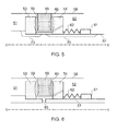
- FIG. 5 shows schematically, for example, a longitudinal cross-section through an intershaft seal which is similar to the seal of Figure 4 except that an axially extending groove 73, 74 is formed in the wall of the inner shaft to act as a pressure equalising flow path.
- two grooves are shown, but in practice only one groove would be present.
- the cavity between the two runners 53, 54 can link to a region of intermediate pressure.
- the region can be inside the inner shaft 57, and the flow path can then be simple hole through the wall of the first shaft, as shown schematically in Figure 6 which is a longitudinal cross-section through an intershaft seal which is similar to the seals of Figures 4 and 5 except that it has such a hole 83 rather than a flow path for pressure equalisation across one of the runners.
- each runner can have a respective compression spring formation on the outward side of the runner.
- Another possibility is to have a tension spring formation which his located in the cavity between the runners, the ends of the spring formation pulling on both the runners.
- the seal of the present invention by having at least one runner that is urged towards the sealing ring, retains an ability to compensate for expansion, build tolerance imperfections and sealing ring wear.
- the swash tolerance of the seal can also be high.
Landscapes
- Engineering & Computer Science (AREA)
- General Engineering & Computer Science (AREA)
- Mechanical Engineering (AREA)
- Mechanical Sealing (AREA)
- Sealing Devices (AREA)
Claims (11)
- Un dispositif d'étanchéité inter-arbres, comprenant
des arbres coaxiaux intérieurs (57) et extérieurs (58) tournant l'un relativement à l'autre ;
une garniture d'étanchéité située dans un espace annulaire entre les arbres, et maintenant, en cours d'usage, un différentiel de pression axiale entre une pression de fluide (51) sur un premier côté de la garniture d'étanchéité et une pression de fluide différente (52) sur un deuxième côté de la garniture d'étanchéité, la garniture d'étanchéité comprenant :Un premier (53) et une deuxième (54) patins faisant saillie dans l'espace annulaire d'un premier des arbres, et s'étendant de façon circonférentielle autour du premier arbre, de sorte qu'une cavité se forme entre les patins, etune bague d'étanchéité (55) coaxiale avec les arbres et située dans la cavité, la bague d'étanchéité possédant une première face d'extrémité (66) et une deuxième face d'extrémité (67) espacées dans l'axe, le premier patin formant une première interface d'étanchéité annulaire (59) avec la première face d'extrémité de la bague d'étanchéité, et le deuxième patin formant une deuxième interface d'étanchéité annulaire (60) avec la deuxième face d'extrémité de la bague d'étanchéité, la bague d'étanchéité effectuant également un contact d'étanchéité avec le deuxième des arbres pour maintenir le différentiel de pression ;un des patins étant à ressort, de sorte qu'il assure un contact d'étanchéité par coulissement axial avec le premier arbre, et soit sollicité vers la bague d'étanchéité,caractérisé par le faitqu'un chemin de fluide (83) s'étend, à travers une paroi du premier arbre, de la cavité formée entre les patins à une zone de pression à mi-chemin entre les pressions exercées sur les premier et deuxième côtés de la garnitures d'étanchéité, le chemin de fluide permettant l'adoption par la cavité de la pression intermédiaire. - Un dispositif d'étanchéité inter-arbres selon la revendication 1, les patins tournant avec le premier arbre.
- Un dispositif d'étanchéité inter-arbres selon une quelconque des revendications précédentes, dans lequel le premier arbre est l'arbre intérieur (57) et le deuxième arbre est l'arbre extérieur (58).
- Un dispositif d'étanchéité inter-arbres selon la revendication 3, la bague d'étanchéité étant sollicitée par centrifugation vers l'arbre extérieur et établit un contact d'étanchéité sur une surface tournée vers l'extérieur de la bague d'étanchéité.
- Un dispositif d'étanchéité inter-arbres selon une quelconque des revendications précédentes, dans lequel le premier arbre est l'arbre extérieur et le deuxième arbre est l'arbre intérieur.
- Un dispositif d'étanchéité inter-arbres selon la revendication 5, la bague d'étanchéité étant fixée en contact d'étanchéité avec l'arbre intérieur sur une surface tournée vers l'intérieur de la bague d'étanchéité.
- Un dispositif d'étanchéité inter-arbres selon une quelconque des revendications précédentes, dans lequel les deux patins sont à ressort de sorte qu'ils soient sollicités vers la bague d'étanchéité.
- Un dispositif d'étanchéité inter-arbres selon une quelconque des revendications précédentes, avec un chemin de fluide (63, 64, 73, 74) s'étendant du premier ou du deuxième côté de la garniture d'étanchéité jusqu'à un emplacement dans la cavité au premier arbre, ou adjacent à celui-ci, le chemin de fluide contournant l'interface d'étanchéité annulaire du patin correspondant et permettant un équilibrage de la pression de fluide entre des côtés à espacement axial de ce patin.
- Un dispositif d'étanchéité inter-arbres selon une quelconque des revendications précédentes, la bague d'étanchéité étant une bague en carbone ou en céramique.
- Un dispositif d'étanchéité inter-arbres selon une quelconque des revendications précédentes, la première et/ou la deuxième l'interface d'étanchéité étant configurée pour produire, en cours d'usage, un soulèvement par dynamique des fluides empêchant ou limitant le contact par coulissement entre la bague d'étanchéité et le patin correspondant sur l'interface.
- Un dispositif d'étanchéité inter-arbres selon la revendication 10, dans lequel à l'interface, ou à chaque interface, se forment des cannelures dans la surface du patin correspondant pour la production d'un soulèvement par dynamique des fluides.
Applications Claiming Priority (1)
| Application Number | Priority Date | Filing Date | Title |
|---|---|---|---|
| GBGB1214476.2A GB201214476D0 (en) | 2012-08-14 | 2012-08-14 | Inshaft seal |
Publications (2)
| Publication Number | Publication Date |
|---|---|
| EP2698568A1 EP2698568A1 (fr) | 2014-02-19 |
| EP2698568B1 true EP2698568B1 (fr) | 2015-07-29 |
Family
ID=46981492
Family Applications (1)
| Application Number | Title | Priority Date | Filing Date |
|---|---|---|---|
| EP13179253.3A Active EP2698568B1 (fr) | 2012-08-14 | 2013-08-05 | Joint d'arbre intermédiaire |
Country Status (3)
| Country | Link |
|---|---|
| US (1) | US8899593B2 (fr) |
| EP (1) | EP2698568B1 (fr) |
| GB (1) | GB201214476D0 (fr) |
Families Citing this family (12)
| Publication number | Priority date | Publication date | Assignee | Title |
|---|---|---|---|---|
| US10663063B2 (en) * | 2014-12-15 | 2020-05-26 | Eaton Intelligent Power Limited | Hydrodynamic seal assembly with interface control |
| US9869198B2 (en) | 2015-05-13 | 2018-01-16 | General Electric Company | Intershaft integrated seal and lock-nut |
| CN105090513A (zh) * | 2015-08-12 | 2015-11-25 | 李纯 | 陶瓷弥散强化金属耐磨带、金属冲压环体浮动油封 |
| US10563530B2 (en) | 2015-10-12 | 2020-02-18 | General Electric Company | Intershaft seal with dual opposing carbon seal rings |
| US10520096B2 (en) | 2015-11-02 | 2019-12-31 | Rolls-Royce Corporation | Intershaft seal assembly |
| US10533567B2 (en) | 2017-05-30 | 2020-01-14 | United Technologies Corporation | Deflection spring seal |
| US11365640B2 (en) | 2019-09-19 | 2022-06-21 | Raytheon Technologies Corporation | Seal assembly with anti-rotation lock |
| WO2022139799A1 (fr) * | 2020-12-22 | 2022-06-30 | Stein Seal Company | Ensemble joint d'étanchéité interposable destiné à l'étanchéité entre des arbres |
| US11506071B2 (en) | 2021-03-02 | 2022-11-22 | Raytheon Technologies Corporation | Piston ring shuttle carrier |
| CN113236598B (zh) * | 2021-06-15 | 2024-06-25 | 江苏长凯机械设备有限公司 | 一种热水泵的密封机构 |
| US11680643B2 (en) | 2021-06-25 | 2023-06-20 | Honeywell International Inc. | Noncontacting intershaft seal system |
| CN115095429B (zh) * | 2022-07-04 | 2025-12-05 | 中国航发贵阳发动机设计研究所 | 一种用于航空发动机转子间滑油腔密封的石墨密封结构 |
Family Cites Families (8)
| Publication number | Priority date | Publication date | Assignee | Title |
|---|---|---|---|---|
| US4266786A (en) * | 1979-08-13 | 1981-05-12 | Borg-Warner Corporation | Mechanical seal assembly |
| JP2804103B2 (ja) * | 1989-08-14 | 1998-09-24 | 株式会社日立製作所 | 同芯二軸用軸封装置 |
| JP3792205B2 (ja) * | 2003-03-03 | 2006-07-05 | 日本ピラー工業株式会社 | メカニカルシール |
| DE102005036338A1 (de) * | 2005-07-29 | 2007-02-15 | Wilo Ag | Gleitringdichtung |
| US8205891B2 (en) | 2008-09-15 | 2012-06-26 | Stein Seal Company | Intershaft seal assembly |
| US8100403B2 (en) | 2008-12-31 | 2012-01-24 | Eaton Corporation | Hydrodynamic intershaft seal and assembly |
| GB201013844D0 (en) * | 2010-08-19 | 2010-09-29 | Rolls Royce Plc | Intershaft seal |
| GB201105625D0 (en) | 2011-04-04 | 2011-05-18 | Rolls Royce Plc | Seal |
-
2012
- 2012-08-14 GB GBGB1214476.2A patent/GB201214476D0/en not_active Ceased
-
2013
- 2013-08-05 US US13/959,215 patent/US8899593B2/en active Active
- 2013-08-05 EP EP13179253.3A patent/EP2698568B1/fr active Active
Also Published As
| Publication number | Publication date |
|---|---|
| US8899593B2 (en) | 2014-12-02 |
| GB201214476D0 (en) | 2012-09-26 |
| EP2698568A1 (fr) | 2014-02-19 |
| US20140049010A1 (en) | 2014-02-20 |
Similar Documents
| Publication | Publication Date | Title |
|---|---|---|
| EP2698568B1 (fr) | Joint d'arbre intermédiaire | |
| US8967627B2 (en) | Intershaft seal | |
| EP2698567B1 (fr) | Joint d'arbre intermédiaire | |
| US11255207B2 (en) | Floating, non-contact seal and dimensions thereof | |
| EP1774208B1 (fr) | Disposition de joint de feuille | |
| EP3232011B1 (fr) | Surpresseur hydrodynamique de joint mécanique en carbone | |
| US20160153306A1 (en) | Radial position control of case support structure with splined connection | |
| US9291066B2 (en) | Methods and systems for sealing a rotary machine using a segmented seal ring | |
| US20110250056A1 (en) | Circumferential sealing arrangement | |
| EP4006311B1 (fr) | Agencement de joint frontal avec force et pression réduites | |
| CN110878760B (zh) | 用于涡轮机械的密封组件 | |
| EP3163017B1 (fr) | Ensemble joint d'étanchéité d'arbre intermédiaire | |
| US11459909B2 (en) | Rotating heat exchanger | |
| US9482158B2 (en) | Turbomachine hybrid lift-off face seal | |
| US10570766B2 (en) | Compliant seal assembly and method of operating | |
| US11371441B2 (en) | Translating fluid delivery device | |
| EP3865741B1 (fr) | Joint labyrinthe à jeu de joint variable | |
| US20060033287A1 (en) | Controlled gap carbon seal | |
| US10557362B2 (en) | Method and system for a pressure activated cap seal | |
| EP2626603B1 (fr) | Joint plat | |
| US11346448B2 (en) | Carbon seal assembly | |
| US12180843B2 (en) | Resiliently deformable seal runner | |
| GB2454014A (en) | Turbine transfer tube | |
| GB2559549A (en) | Pump assembly |
Legal Events
| Date | Code | Title | Description |
|---|---|---|---|
| AK | Designated contracting states |
Kind code of ref document: A1 Designated state(s): AL AT BE BG CH CY CZ DE DK EE ES FI FR GB GR HR HU IE IS IT LI LT LU LV MC MK MT NL NO PL PT RO RS SE SI SK SM TR |
|
| AX | Request for extension of the european patent |
Extension state: BA ME |
|
| PUAI | Public reference made under article 153(3) epc to a published international application that has entered the european phase |
Free format text: ORIGINAL CODE: 0009012 |
|
| 17P | Request for examination filed |
Effective date: 20140814 |
|
| RBV | Designated contracting states (corrected) |
Designated state(s): AL AT BE BG CH CY CZ DE DK EE ES FI FR GB GR HR HU IE IS IT LI LT LU LV MC MK MT NL NO PL PT RO RS SE SI SK SM TR |
|
| RIC1 | Information provided on ipc code assigned before grant |
Ipc: F16J 15/34 20060101AFI20150311BHEP |
|
| GRAP | Despatch of communication of intention to grant a patent |
Free format text: ORIGINAL CODE: EPIDOSNIGR1 |
|
| INTG | Intention to grant announced |
Effective date: 20150421 |
|
| GRAP | Despatch of communication of intention to grant a patent |
Free format text: ORIGINAL CODE: EPIDOSNIGR1 |
|
| GRAS | Grant fee paid |
Free format text: ORIGINAL CODE: EPIDOSNIGR3 |
|
| GRAA | (expected) grant |
Free format text: ORIGINAL CODE: 0009210 |
|
| INTG | Intention to grant announced |
Effective date: 20150609 |
|
| AK | Designated contracting states |
Kind code of ref document: B1 Designated state(s): AL AT BE BG CH CY CZ DE DK EE ES FI FR GB GR HR HU IE IS IT LI LT LU LV MC MK MT NL NO PL PT RO RS SE SI SK SM TR |
|
| RAP1 | Party data changed (applicant data changed or rights of an application transferred) |
Owner name: ROLLS-ROYCE PLC |
|
| REG | Reference to a national code |
Ref country code: GB Ref legal event code: FG4D |
|
| REG | Reference to a national code |
Ref country code: CH Ref legal event code: EP |
|
| REG | Reference to a national code |
Ref country code: AT Ref legal event code: REF Ref document number: 739590 Country of ref document: AT Kind code of ref document: T Effective date: 20150815 |
|
| REG | Reference to a national code |
Ref country code: IE Ref legal event code: FG4D |
|
| REG | Reference to a national code |
Ref country code: DE Ref legal event code: R096 Ref document number: 602013002427 Country of ref document: DE |
|
| REG | Reference to a national code |
Ref country code: AT Ref legal event code: MK05 Ref document number: 739590 Country of ref document: AT Kind code of ref document: T Effective date: 20150729 |
|
| REG | Reference to a national code |
Ref country code: LT Ref legal event code: MG4D |
|
| REG | Reference to a national code |
Ref country code: NL Ref legal event code: MP Effective date: 20150729 |
|
| PG25 | Lapsed in a contracting state [announced via postgrant information from national office to epo] |
Ref country code: LV Free format text: LAPSE BECAUSE OF FAILURE TO SUBMIT A TRANSLATION OF THE DESCRIPTION OR TO PAY THE FEE WITHIN THE PRESCRIBED TIME-LIMIT Effective date: 20150729 Ref country code: LT Free format text: LAPSE BECAUSE OF FAILURE TO SUBMIT A TRANSLATION OF THE DESCRIPTION OR TO PAY THE FEE WITHIN THE PRESCRIBED TIME-LIMIT Effective date: 20150729 Ref country code: FI Free format text: LAPSE BECAUSE OF FAILURE TO SUBMIT A TRANSLATION OF THE DESCRIPTION OR TO PAY THE FEE WITHIN THE PRESCRIBED TIME-LIMIT Effective date: 20150729 Ref country code: NO Free format text: LAPSE BECAUSE OF FAILURE TO SUBMIT A TRANSLATION OF THE DESCRIPTION OR TO PAY THE FEE WITHIN THE PRESCRIBED TIME-LIMIT Effective date: 20151029 Ref country code: GR Free format text: LAPSE BECAUSE OF FAILURE TO SUBMIT A TRANSLATION OF THE DESCRIPTION OR TO PAY THE FEE WITHIN THE PRESCRIBED TIME-LIMIT Effective date: 20151030 |
|
| PG25 | Lapsed in a contracting state [announced via postgrant information from national office to epo] |
Ref country code: ES Free format text: LAPSE BECAUSE OF FAILURE TO SUBMIT A TRANSLATION OF THE DESCRIPTION OR TO PAY THE FEE WITHIN THE PRESCRIBED TIME-LIMIT Effective date: 20150729 Ref country code: PL Free format text: LAPSE BECAUSE OF FAILURE TO SUBMIT A TRANSLATION OF THE DESCRIPTION OR TO PAY THE FEE WITHIN THE PRESCRIBED TIME-LIMIT Effective date: 20150729 Ref country code: HR Free format text: LAPSE BECAUSE OF FAILURE TO SUBMIT A TRANSLATION OF THE DESCRIPTION OR TO PAY THE FEE WITHIN THE PRESCRIBED TIME-LIMIT Effective date: 20150729 Ref country code: AT Free format text: LAPSE BECAUSE OF FAILURE TO SUBMIT A TRANSLATION OF THE DESCRIPTION OR TO PAY THE FEE WITHIN THE PRESCRIBED TIME-LIMIT Effective date: 20150729 Ref country code: RS Free format text: LAPSE BECAUSE OF FAILURE TO SUBMIT A TRANSLATION OF THE DESCRIPTION OR TO PAY THE FEE WITHIN THE PRESCRIBED TIME-LIMIT Effective date: 20150729 Ref country code: SE Free format text: LAPSE BECAUSE OF FAILURE TO SUBMIT A TRANSLATION OF THE DESCRIPTION OR TO PAY THE FEE WITHIN THE PRESCRIBED TIME-LIMIT Effective date: 20150729 Ref country code: PT Free format text: LAPSE BECAUSE OF FAILURE TO SUBMIT A TRANSLATION OF THE DESCRIPTION OR TO PAY THE FEE WITHIN THE PRESCRIBED TIME-LIMIT Effective date: 20151130 Ref country code: IS Free format text: LAPSE BECAUSE OF FAILURE TO SUBMIT A TRANSLATION OF THE DESCRIPTION OR TO PAY THE FEE WITHIN THE PRESCRIBED TIME-LIMIT Effective date: 20151129 |
|
| PG25 | Lapsed in a contracting state [announced via postgrant information from national office to epo] |
Ref country code: NL Free format text: LAPSE BECAUSE OF FAILURE TO SUBMIT A TRANSLATION OF THE DESCRIPTION OR TO PAY THE FEE WITHIN THE PRESCRIBED TIME-LIMIT Effective date: 20150729 |
|
| PG25 | Lapsed in a contracting state [announced via postgrant information from national office to epo] |
Ref country code: MC Free format text: LAPSE BECAUSE OF FAILURE TO SUBMIT A TRANSLATION OF THE DESCRIPTION OR TO PAY THE FEE WITHIN THE PRESCRIBED TIME-LIMIT Effective date: 20150729 Ref country code: CZ Free format text: LAPSE BECAUSE OF FAILURE TO SUBMIT A TRANSLATION OF THE DESCRIPTION OR TO PAY THE FEE WITHIN THE PRESCRIBED TIME-LIMIT Effective date: 20150729 Ref country code: IT Free format text: LAPSE BECAUSE OF FAILURE TO SUBMIT A TRANSLATION OF THE DESCRIPTION OR TO PAY THE FEE WITHIN THE PRESCRIBED TIME-LIMIT Effective date: 20150729 Ref country code: SK Free format text: LAPSE BECAUSE OF FAILURE TO SUBMIT A TRANSLATION OF THE DESCRIPTION OR TO PAY THE FEE WITHIN THE PRESCRIBED TIME-LIMIT Effective date: 20150729 Ref country code: DK Free format text: LAPSE BECAUSE OF FAILURE TO SUBMIT A TRANSLATION OF THE DESCRIPTION OR TO PAY THE FEE WITHIN THE PRESCRIBED TIME-LIMIT Effective date: 20150729 Ref country code: EE Free format text: LAPSE BECAUSE OF FAILURE TO SUBMIT A TRANSLATION OF THE DESCRIPTION OR TO PAY THE FEE WITHIN THE PRESCRIBED TIME-LIMIT Effective date: 20150729 |
|
| REG | Reference to a national code |
Ref country code: DE Ref legal event code: R097 Ref document number: 602013002427 Country of ref document: DE |
|
| REG | Reference to a national code |
Ref country code: DE Ref legal event code: R082 Ref document number: 602013002427 Country of ref document: DE Representative=s name: HERNANDEZ, YORCK, DIPL.-ING., DE |
|
| PG25 | Lapsed in a contracting state [announced via postgrant information from national office to epo] |
Ref country code: RO Free format text: LAPSE BECAUSE OF FAILURE TO SUBMIT A TRANSLATION OF THE DESCRIPTION OR TO PAY THE FEE WITHIN THE PRESCRIBED TIME-LIMIT Effective date: 20150729 |
|
| REG | Reference to a national code |
Ref country code: IE Ref legal event code: MM4A |
|
| PLBE | No opposition filed within time limit |
Free format text: ORIGINAL CODE: 0009261 |
|
| STAA | Information on the status of an ep patent application or granted ep patent |
Free format text: STATUS: NO OPPOSITION FILED WITHIN TIME LIMIT |
|
| 26N | No opposition filed |
Effective date: 20160502 |
|
| PG25 | Lapsed in a contracting state [announced via postgrant information from national office to epo] |
Ref country code: IE Free format text: LAPSE BECAUSE OF NON-PAYMENT OF DUE FEES Effective date: 20150805 |
|
| REG | Reference to a national code |
Ref country code: FR Ref legal event code: PLFP Year of fee payment: 4 |
|
| PG25 | Lapsed in a contracting state [announced via postgrant information from national office to epo] |
Ref country code: SI Free format text: LAPSE BECAUSE OF FAILURE TO SUBMIT A TRANSLATION OF THE DESCRIPTION OR TO PAY THE FEE WITHIN THE PRESCRIBED TIME-LIMIT Effective date: 20150729 |
|
| PG25 | Lapsed in a contracting state [announced via postgrant information from national office to epo] |
Ref country code: MT Free format text: LAPSE BECAUSE OF FAILURE TO SUBMIT A TRANSLATION OF THE DESCRIPTION OR TO PAY THE FEE WITHIN THE PRESCRIBED TIME-LIMIT Effective date: 20150729 |
|
| REG | Reference to a national code |
Ref country code: CH Ref legal event code: PL |
|
| PG25 | Lapsed in a contracting state [announced via postgrant information from national office to epo] |
Ref country code: LI Free format text: LAPSE BECAUSE OF NON-PAYMENT OF DUE FEES Effective date: 20160831 Ref country code: CH Free format text: LAPSE BECAUSE OF NON-PAYMENT OF DUE FEES Effective date: 20160831 |
|
| PG25 | Lapsed in a contracting state [announced via postgrant information from national office to epo] |
Ref country code: BG Free format text: LAPSE BECAUSE OF FAILURE TO SUBMIT A TRANSLATION OF THE DESCRIPTION OR TO PAY THE FEE WITHIN THE PRESCRIBED TIME-LIMIT Effective date: 20150729 Ref country code: HU Free format text: LAPSE BECAUSE OF FAILURE TO SUBMIT A TRANSLATION OF THE DESCRIPTION OR TO PAY THE FEE WITHIN THE PRESCRIBED TIME-LIMIT; INVALID AB INITIO Effective date: 20130805 |
|
| PG25 | Lapsed in a contracting state [announced via postgrant information from national office to epo] |
Ref country code: CY Free format text: LAPSE BECAUSE OF FAILURE TO SUBMIT A TRANSLATION OF THE DESCRIPTION OR TO PAY THE FEE WITHIN THE PRESCRIBED TIME-LIMIT Effective date: 20150729 |
|
| PG25 | Lapsed in a contracting state [announced via postgrant information from national office to epo] |
Ref country code: BE Free format text: LAPSE BECAUSE OF NON-PAYMENT OF DUE FEES Effective date: 20150831 |
|
| REG | Reference to a national code |
Ref country code: FR Ref legal event code: PLFP Year of fee payment: 5 |
|
| PG25 | Lapsed in a contracting state [announced via postgrant information from national office to epo] |
Ref country code: LU Free format text: LAPSE BECAUSE OF NON-PAYMENT OF DUE FEES Effective date: 20150805 |
|
| PG25 | Lapsed in a contracting state [announced via postgrant information from national office to epo] |
Ref country code: SM Free format text: LAPSE BECAUSE OF FAILURE TO SUBMIT A TRANSLATION OF THE DESCRIPTION OR TO PAY THE FEE WITHIN THE PRESCRIBED TIME-LIMIT Effective date: 20150729 |
|
| PG25 | Lapsed in a contracting state [announced via postgrant information from national office to epo] |
Ref country code: TR Free format text: LAPSE BECAUSE OF FAILURE TO SUBMIT A TRANSLATION OF THE DESCRIPTION OR TO PAY THE FEE WITHIN THE PRESCRIBED TIME-LIMIT Effective date: 20150729 Ref country code: MK Free format text: LAPSE BECAUSE OF FAILURE TO SUBMIT A TRANSLATION OF THE DESCRIPTION OR TO PAY THE FEE WITHIN THE PRESCRIBED TIME-LIMIT Effective date: 20150729 |
|
| REG | Reference to a national code |
Ref country code: FR Ref legal event code: PLFP Year of fee payment: 6 |
|
| PG25 | Lapsed in a contracting state [announced via postgrant information from national office to epo] |
Ref country code: AL Free format text: LAPSE BECAUSE OF FAILURE TO SUBMIT A TRANSLATION OF THE DESCRIPTION OR TO PAY THE FEE WITHIN THE PRESCRIBED TIME-LIMIT Effective date: 20150729 |
|
| P01 | Opt-out of the competence of the unified patent court (upc) registered |
Effective date: 20230528 |
|
| PGFP | Annual fee paid to national office [announced via postgrant information from national office to epo] |
Ref country code: DE Payment date: 20250827 Year of fee payment: 13 |
|
| PGFP | Annual fee paid to national office [announced via postgrant information from national office to epo] |
Ref country code: GB Payment date: 20250826 Year of fee payment: 13 |
|
| PGFP | Annual fee paid to national office [announced via postgrant information from national office to epo] |
Ref country code: FR Payment date: 20250825 Year of fee payment: 13 |