EP2700516A2 - Attelage - Google Patents
Attelage Download PDFInfo
- Publication number
- EP2700516A2 EP2700516A2 EP13179557.7A EP13179557A EP2700516A2 EP 2700516 A2 EP2700516 A2 EP 2700516A2 EP 13179557 A EP13179557 A EP 13179557A EP 2700516 A2 EP2700516 A2 EP 2700516A2
- Authority
- EP
- European Patent Office
- Prior art keywords
- lever
- trailer coupling
- locking pin
- coupling according
- shell
- Prior art date
- Legal status (The legal status is an assumption and is not a legal conclusion. Google has not performed a legal analysis and makes no representation as to the accuracy of the status listed.)
- Granted
Links
Images


Classifications
-
- B—PERFORMING OPERATIONS; TRANSPORTING
- B60—VEHICLES IN GENERAL
- B60D—VEHICLE CONNECTIONS
- B60D1/00—Traction couplings; Hitches; Draw-gear; Towing devices
- B60D1/01—Traction couplings or hitches characterised by their type
- B60D1/06—Ball-and-socket hitches
- B60D1/065—Ball-and-socket hitches characterised by the hitch mechanism
Definitions
- the invention relates to a trailer coupling with the features in the main claim.
- Such a hitch is from the DE 20 2005 011 444 U1 known. It has a clutch housing with an operating lever, a locking pin, a pivotable ball socket and a pivotable locking lever, which forms a Einrastêt and cooperates with the locking pin.
- the invention solves this problem with the features in the main claim.
- the claimed towing hitch has the advantage that thanks to the freely rotatable in the open position and independently of the locking lever and the locking pin spherical shell false locks the trailer hitch can be reliably avoided. When in contact with an obstacle or with a wrongly supplied coupling ball ball shell can escape independently of the safety lever and the locking pin. You can also solve the lock pin trouble-free. The locking lever and the locking bolt remain untouched in their blocking position, so that the towing hitch can not accidentally close and lock. Operating errors when coupling and errors of the operator about the coupling state can be reliably avoided.
- a convex curvature or rounding on the underside of the shell bottom has the advantage of a Einweiser- and guide function in case of incorrect operation with loosely mounted towing hitch and subsequent Gespannfahrt.
- the hitch can be closed automatically and the ball head can be brought into a correct latching position.
- a rear curved contact contour on the spherical shell can on the one hand form a stop for limiting the rotational movement in the open position on the locking bolt, the remaining contour area being distanced from the locking bolt by the rearwardly projecting securing lever and the aforementioned avoidance and rotation of the spherical shell in the opposite direction upon collision with an obstacle or the like allows.
- the ball cup has a defined opening position by the stop and the spring load.
- the safety lever fails, e.g. by breakage or the like., The contact contour with the spring-loaded locking bolt in supporting and the open position locking engagement occur. As a result, the coupling function can be retained.
- the ball socket and the safety lever are mounted coaxially pivotable.
- the ball shell has in one embodiment at the rear end region of one or more upper Zuspann- and Nachstell lake for the system on the locking pin in the closed position. It may also have at the rear end portion an upper locking surface for engagement with the locking pin in part-opening position.
- the safety lever is rod-shaped and arranged in the free space of the spherical shell. He can reach through or over the front wall of the ball shell, which is advantageous, but not mandatory.
- a further embodiment provides that the pivotable operating lever has a lever bearing, driver for the locking pin and a pawl.
- the arrangement of a wear indicator on the operating lever may be advantageous.
- a spring-loaded training of control lever and safety lever may also be provided.
- the invention relates to a trailer coupling (1) for vehicles (not shown), in particular for trailers.
- FIGS. 1 to 13 and 14 to 16 show different coupling variants.
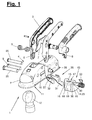
- FIG. 1 Such a hitch (1) and its parts are shown in an exploded perspective view.
- the hitch (1) has a substantially U-shaped coupling housing (2), which is arranged and fixed in a suitable manner on a front-side vehicle part, for example on a rigid drawbar or on the rod of a trailer device of a trailer.
- the trailer parts are not shown for clarity.
- the coupling housing (2) has at the front a downwardly and rearwardly open and in dome-shaped dome shaped receiving opening (11) for a ball head (12) of a trailer hitch on a towing vehicle (not shown).
- the coupling housing (2) can have an opening for the latching indicator (28) explained below in this area on the upper side.
- the clutch housing (2) also has at the top an opening for an operating member (3), in particular a pivotable operating lever or clutch lever. Furthermore, housing openings for a lever bearing (4) of the operating lever (3) and for a subsequently explained storage of a spherical shell (13) and a safety lever (26) are present. In FIG. 1 Here are also the associated and plugged bearing pins (25) shown.
- two longitudinally directed bolt guides (10) for a locking pin (9) are arranged on the side walls of the coupling housing, which are formed for example as elongated holes with parallel axial hole edges.
- the trailer coupling (1) has a ball socket (13), which is arranged to be movable, in particular pivotable, in the coupling housing and at the rear area of the dome-shaped receiving opening (11).
- the ball shell (13) cooperates in the closed position and during the closing process of the trailer coupling (1) with the transversely pushed through locking bolt (9), which in turn is in an actuating connection with the operating lever (3).
- the hitch (1) further comprises a locking lever arranged on the inside (26).
- the safety lever (26) cooperates with the locking pin (9) and blocks it when the trailer coupling (1) is open.
- the hitch (1) can be closed only after solving this blockade.
- the ball socket (13) and the safety lever (26) are pivotally mounted on the clutch housing (2). This is preferably an equiaxial bearing on a common bearing pin (25). A spring (33) acts on the securing lever (26) and possibly the ball socket (13).
- the bearing opening on the lateral housing walls is preferably arranged on the front region of the coupling housing (2) and in front of the bolt guide (10).
- the spherical shell (13) has a front wall (16) with a front concave depression (19) and a driving stop (18) arranged above it.
- closed position of the hitch (1) is the ball head (12) positively received in the housing side receiving opening (11) and in the trough (19), wherein the ball shell (13) in this closed position by the locking pin (9) acted upon and against the ball head ( 12) is tensioned.
- the driving stop (18) ensures that the spherical shell (13) is taken in each rotational position of a correctly dipping ball head (12) and brought into a position which allows an application and tension by the locking pin (9).
- the ball socket (13) at the rear end face a contact contour (22) for a releasable contact with the locking pin (9) in the open position of the trailer coupling (1).
- the contact contour (22) has a cup-like curved concave shape. It forms on the one hand a stop for contact with the underside of the locking bolt (9), which limits the opening rotation of the ball socket (13).
- the contact contour (22) allows a free pivoting movement of the ball socket (13) and unhindered release from the locking pin (9).
- the contact contour (22) can produce a slight clamping connection with the locking bolt (9) in the stop position, which, however, can be easily detached.
- the ball shell (13) further has at the upper rear end region on an overhead Zuspann- and Nachstell structure (20), which is provided for engagement with the locking pin (9) in the closed position.
- the operated by the operating lever (3) locking pin (9) slides on here and presses when closing the trailer hitch (1) the ball socket (13) in the FIGS. 4 and 5 shown closed position.
- the application and adjustment surface (20) is oriented obliquely to the direction of adjustment of the locking bolt (9) and allows readjustment and re-pressing in smaller diameter or worn coupling balls or ball heads (12).
- the ball cup (13) further has at the rear end portion an upper locking surface (21) which has a slight upward inclination towards the rear end and for the system on the locking pin (9) in a part-opening position of the trailer coupling (1) provides.
- the blocking surface (21) ensures that a partially opened trailer coupling (1) can not accidentally or by itself without actuation of the operating lever (3) can open and uncouple.
- the ball shell (13) also has on its shell bottom (14) a downwardly directed convex rounding (23).
- the transition of the rounded tray bottom (14) in the upright front wall (16) is formed as a round edge (36).
- FIG. 1 . 3 . 7 . 9 . 12, 13 and 15 show this embodiment.
- the ball socket (13) has a fork shape, which is formed by an upright front wall (16), a lower and only over a partial length of the ball shell (13) reaching shell bottom (14) and bilateral shell arms (15) over the extend the entire length and together with the front wall (16) enclose a free space (17).
- an in FIG. 1 represented spring (33) are received.
- the lateral shell arms (15) have at the front region in each case a bearing opening (24) for the bearing pin (25) and at the rear end region the abovementioned contact contour (22), blocking surface (21) and clamping and adjusting surface (20).
- the trained as a curved thin-walled sheet metal part safety lever also has a fork or U-shape. It consists of a lever arm (32) arranged transversely in front of the ball shell (13) and two lever arms (31) extending past on both sides on the outside of the ball shell (13).
- the lever arms (31) bearing bearing openings (30) for the bearing pin (25) and have at the rear, preferably the front end, a positive bolt receptacle (29) itself can lock on the locking pin (9).
- the trigger (27) may have a wear-resistant spherical shell shape. FIG. 5 shows this closing lever position.
- the securing lever (26) also has an upwardly directed and possibly color-contrasting snap-in indicator (28), which projects into the closed position through the above-mentioned upper housing opening. It is visible from the outside and signals, for example, by position and color the correct assumption of the closed position.
- the longitudinal lever arms (31) are located below the locking bolt (9) and below the clamping and adjusting surface (s) (20).
- the safety lever (26) engages with its thin upright lever arms (31,32) front and side of the ball socket (13), which can rotate freely and independently of the safety lever (26) and its lever position.
- the locking pin (9) is positively connected to the operating lever (3) via driver (6), for example in the form of obliquely directed slots.
- the pushed-through locking pin (9) is guided on the upright slot edges and is taken on a pivoting movement of the operating lever (3) on the high-level lever bearing (4) and pushed back and forth depending on the direction of rotation in the pin guide (10).
- the operating lever (3) can eg according to FIG. 1 be formed in one or more parts, wherein it consists for example of several, laterally assembled shell parts, which at the lower and preferably straight end of the lever said slots (6) and at the upper end of the lever have a handle part and possibly a in FIG. 1 Record the lock shown.
- a spring-loaded pawl (7) is further arranged, which projects with its pawl nose forward over the lever edge and cooperates with an opening on the housing top. It prevents accidental opening of the towing hitch (1) and can only dip into said opening when an operator folds it against the spring force and turns the operating lever (3).
- the operating lever (3) may also have a wear indicator (8) on the back. This can, for example, depending on the wear-dependent Zuspann- and rotational position of the operating lever (3) show a color marking or the like. On a curved marking carrier.
- FIG. 1 illustrates springs (5,33) are present, which act on the operating lever (3) and the locking pin (9) and the locking lever (26) and possibly the ball socket (13).
- the upper and the operating lever (3) and the locking pin (9) associated spring (5) is supported on the clutch housing (2) and acts in the closing direction of the hitch (1), wherein the operating lever (3) and the locking pin (9) pushes forward to the receiving opening (11).
- the spring (33) tries to move the safety lever (26) and the ball socket (13) into an open position, this path being limited by a stop in cooperation with the locking pin (9).
- FIG. 3 shows the open position with the counterclockwise in this side view about the pin axis (25) directed and symbolized by an arrow rotating spring action.
- the bolt receptacle (29) on the locking lever (26) has the shape of a cup-shaped latching opening with a contour adapted to the locking pin (9).
- the bolt receptacle (29) engages positively around a portion of the front bolt wall above and below the central axis of the locking bolt (9). The positive engagement holds the safety lever (26) with the trailer coupling (1) open in the open position shown, in which the trigger (28) projects into the receiving opening (11).
- the upper curved contour edge is just above the central axis of the locking bolt (9) and thereby forms a positive locking.
- the force exerted by the spring-loaded locking pin (9) and at the contact point to the bolt receptacle (29) resulting normal force F also passes above the locking lever bearing (25) and secures the locking positive locking mutual position of safety lever (26) and locking pin (9).
- open position of the locking pin (9) is held by the safety lever (26) and can not move forward in its closed position and in a pressurizing contact with the adjusting surface (20) of the ball socket (13).
- a release is only possible when a correctly dipping ball (12) abuts the trigger (27) and solves the lever and bolt engagement upon actuation of the operating lever, so that then the closed position in accordance with FIG. 5 can be taken.
- the safety lever (26) prevents in the in FIG. 3 also shown that the operating lever (3) pivoted downward and the clutch is closed.
- the ball socket (13) in the open position of the trailer hitch (1) is freely pivotable about the bearing pin (25), where they can also move freely and independently of the safety lever (26) and the locking pin (9).
- the Ball shell (13) in such a pivoting movement no entrainment function for the safety lever (26) and the locking pin (9). Rather, it can rotate freely, without causing an operation and accidental closing of the trailer hitch (1).
- the safety lever (26) and the locking pin (9) retain the in FIG. 3 Blockade position shown.
- the ball socket (13) thanks to the contact contour (22) and the spring loading a defined open position.
- FIGS. 12 and 13 clarify the free rotation of the ball shell (13) by a length adjustment of ball socket (13) and locking lever (26) and their rear areas is reached.
- the safety lever (26) protrudes in the open position to the rear a piece on the ball socket (13) and the shell arms (15) out.
- the contact contour (22) on the ball shell (13) or on its shell arms (15) strikes only on the underside of the locking bolt (19) and is otherwise distanced to the front by a distance (x) so far from the locking pin (9) in that the said free rotary movement in the open position is possible.
- FIG. 2 shows the means of the spring (33) defined opening and stop position on the locking pin (9).
- FIG. 13 shows another rotational position, which can take the ball socket (13) with the trailer coupling (1) open.
- FIGS. 12 and 13 illustrate the training of the plant contour (22). It has a cup-like curved concave shape and has a lower, rearwardly projecting contour portion or stop area (34) and an upper contour portion or shell portion (35).
- the lower stop area (34) protrudes so far back that he in the open position according to FIG. 12 on the underside of the locking bolt (9).
- the upper contour portion (35) is in the open position of a intact safety lever (26) as far as the distance (x) from the locking pin (9) distanced that the said free pivoting movement is possible.
- the upper contour portion (35) has a shell shape, which can occur in a break or other failure of the safety lever (26) with the then pushed by its spring (5) further forward locking pin (9) in positive engagement.
- the shell shape is chosen so that the upper shell region engages and supports the locking pin (9) in certain areas and develops a support moment (M) securing the open position. This results in the contact point with the locking pin (9) has a resulting normal force (F), which extends above the pin and bearing axis (25).
- the formation of the upper contour section or shell region (35) of the contact contour (22) and the formation of the bent bolt receptacle or latching opening (29) on the securing lever (26) can be of similar design.
- FIGS. 12 and 13 is the interaction with the locking pin (9) shown on the basis of the bolt receptacle (29) and applies accordingly also for the contact contour (22) in the aforementioned failure of the safety lever (26).
- the hitch (1) with the freely rotatable and designed in the manner described ball socket (13) has positive safety effects in an incorrect operation, the below with reference to FIGS. 6 to 11 shown and described.
- FIGS. 6 and 7 show a first collision situation in which the hitch (1) is pushed too far over the ball head (12) in an incorrect operation and does not lock.
- the ball socket (13) contacted with her curved tray bottom (14) behind the bearing (25) the ball head (12). It is thereby pressed with its rear contact contour (22) or the stopper area (34) against the locking pin (9) and supported there, wherein the locking pin (9) retains its position and does not yield.
- Such a collision thus has no effect on the opening and Blockadegna shown with the mutual positive engagement of safety lever (26) and locking pin (9).
- the hitch (1) can not be locked in this position despite actuation of the operating lever (3) and released pawl (7).
- the blocking engagement of safety lever (26) and locking pin (9) is maintained.
- FIGS. 8 and 9 show a different collision situation, in which the ball head (12) the ball shell (13) on the curved (23) shell bottom (14) contacted more forward or with a possibly forward movement component.
- the spherical shell (13) is thereby taken freely rotating and released from the stop position on the locking pin (9), without the positive blockage position between locking lever (26) and locking pin (9) is negatively affected.
- the spherical shell (13) can perform an evasive movement without negative influence on the trailer coupling (1). It can narrow the access to the receiving opening (11) and have a locking and locking function for the ball head (12).
- the ball head (12) can not engage in the manual coupling anywhere on the trailer hitch and falsely suggest a coupling and locking position.
- the Blockadegna of safety lever (26) and locking pin (9) is not canceled.
- the spring (33) rotates the ball socket (13) back into the stop position on the locking pin (9).
- FIGS. 10 and 11 show a correct Ankuppelgna in which the ball head (12) occupies the correct Ankuppelposition below the receiving opening (11) and located in the stop position ball socket (13).
- FIGS. 6 to 11 refer to static situations in which an operator may incorrectly position and attach the hitch (1) and the hitch housing (2) to a stationary vehicle and stationary ball head (12).
- FIG. 9 clarifies this position.
- the ball head (12) contacts the trigger (27), whereby the load is so great that the bolt receptacle (29) snaps out of engagement with the locking bolt (9), whereby the blockage position is canceled and that of spring force advanced locking bolt (9), the ball socket (13) tensioned and the hitch (1) closes.
- the operating lever (3) is taken along. The operating error with the loosely mounted towing hitch (1) can thereby automatically remedied when driving thanks to the pivotable spherical shell (13) and possibly its rounding (23) and the hitch (1) automatically locked and closed.
- FIGS. 14 to 16 show a variant of the trailer coupling (1) which differs from the embodiment of FIGS. 1 to 13 distinguished by the design and mutual association of the ball socket (13) and the safety lever (26).
- the other coupling components may be the same as in the first embodiment and have the same reference numerals.
- the safety lever (26) is formed in this embodiment, rod-like or one arm and is housed within the free space (17) of the spherical shell (13) between the shell arms (15).
- the spherical shell (13) and in particular its front wall (16) can thereby have a greater width than in the first embodiment.
- the spherical shell (13) and the securing lever (26) are coaxially and jointly mounted on the bearing pin (25) in this embodiment.
- the safety lever (26) has at the rear end of the bolt receptacle (29) and can in the arm area before as in the first embodiment, a recess for the clearance of the operating lever (3).
- the front part of the Safety lever (26) has in the second variant a cranked shape and engages over or through the upper edge of the front wall (16) of the spherical shell (13).
- the front arm end also has a trigger (27).
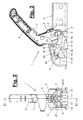
- FIG. 14 shows the second variant in rear view, where FIG. 15 the corresponding longitudinal section according to section line XV-XV represents.
- the open position of the trailer coupling (1) with the in the receiving opening (11) projecting trigger (27) is shown.
- the spherical shell (13) is also free or possibly under restoring action of a spring rotatably mounted about the bearing pin (25) and has at the rear end an investment contour (not shown) which abuts in the open position on the locking pin (9) and on the other hand in the coupling longitudinal direction by the rearwardly projecting locking lever (26) from the locking pin (9) is distanced.
- FIG. 16 shows the closed position of the trailer hitch (1).
- the second variant shown here pivots the front part of the safety lever (26) with the trigger (27) in a free space in the upper region of the coupling housing (2).
- this second variant is dispensed with a Einrast researcher or this is formed in another way and independently of the safety lever (26).
- the rotatable coupling shell (13) and the locking lever (26) have the same function as in the first embodiment. You can also use the security and instructor feature described above FIGS. 6 to 11 to have.
- the locking pin (9) can be fixed to the operating lever (3) to be appropriate.
- the ball socket (13) and the safety lever (26) may have a different adapted shape and other bearings, the above functions and the decoupling of the ball socket (13) from the locking pin (9) and the safety lever (26) in the open position of the clutch (1 ) preserved.
- the contact contour (22) on the coupling shell (13) may be L-shaped or otherwise formed, wherein the positive engagement on the locking pin (9) is dispensed with failure of the safety lever (26).
- a safety lever (26) having the features of claim 11 and / or 12 and / or 13 and / or 14 and / or 15 can be used in any hitch (1) having a clutch housing (2), an operating lever (3) and having an arbitrarily pivotally mounted spherical shell (13).
- a trailer coupling (1) may possibly also have a locking bolt (9) which is displaceably mounted in the coupling housing (2) and with which the securing lever (26) can cooperate. Both, however, is not mandatory.
Landscapes
- Engineering & Computer Science (AREA)
- Transportation (AREA)
- Mechanical Engineering (AREA)
- Mechanical Control Devices (AREA)
- Quick-Acting Or Multi-Walled Pipe Joints (AREA)
Applications Claiming Priority (1)
| Application Number | Priority Date | Filing Date | Title |
|---|---|---|---|
| DE202012103133U DE202012103133U1 (de) | 2012-08-20 | 2012-08-20 | Anhängekupplung |
Publications (3)
| Publication Number | Publication Date |
|---|---|
| EP2700516A2 true EP2700516A2 (fr) | 2014-02-26 |
| EP2700516A3 EP2700516A3 (fr) | 2014-11-26 |
| EP2700516B1 EP2700516B1 (fr) | 2018-03-07 |
Family
ID=48918283
Family Applications (1)
| Application Number | Title | Priority Date | Filing Date |
|---|---|---|---|
| EP13179557.7A Active EP2700516B1 (fr) | 2012-08-20 | 2013-08-07 | Attelage |
Country Status (2)
| Country | Link |
|---|---|
| EP (1) | EP2700516B1 (fr) |
| DE (1) | DE202012103133U1 (fr) |
Cited By (1)
| Publication number | Priority date | Publication date | Assignee | Title |
|---|---|---|---|---|
| US11654734B2 (en) | 2020-12-23 | 2023-05-23 | Korea Wheel Corporation | Actuator coupler for hitch connection |
Families Citing this family (1)
| Publication number | Priority date | Publication date | Assignee | Title |
|---|---|---|---|---|
| DE202014106153U1 (de) * | 2014-12-18 | 2015-02-10 | Al-Ko Kober Ges. M.B.H | Betätigungsgriff für eine Anhängekupplung mit Vorbereitung für ein Schloss |
Citations (2)
| Publication number | Priority date | Publication date | Assignee | Title |
|---|---|---|---|---|
| DE19533202A1 (de) | 1995-09-08 | 1997-03-13 | Berndes Fa Albert | Kugelkopfkupplung |
| DE202005011444U1 (de) | 2005-07-18 | 2006-11-16 | Al-Ko Kober Ag | Anhängerkupplung mit Einrastsicherung |
Family Cites Families (5)
| Publication number | Priority date | Publication date | Assignee | Title |
|---|---|---|---|---|
| DE6603849U (de) | 1966-10-12 | 1969-11-06 | Kurt Dipl Ing Dr Karnath | Kugelkopfkupplung mit bolzenverriegelung |
| US4209184A (en) * | 1978-08-30 | 1980-06-24 | Byers Dwight R | Self-locking trailer hitch assembly |
| DE4303164A1 (en) * | 1992-02-06 | 1993-08-12 | Westfalia Werke Knoebel | Trailer coupling with friction brake for motor vehicle |
| DE9412514U1 (de) | 1994-08-03 | 1995-06-14 | AL-KO Kober AG, 89359 Kötz | Kugelkopf-Anhängerkupplung |
| DE202010000223U1 (de) | 2010-02-18 | 2011-07-07 | Al-Ko Kober Ag | Anhängerkupplung |
-
2012
- 2012-08-20 DE DE202012103133U patent/DE202012103133U1/de not_active Expired - Lifetime
-
2013
- 2013-08-07 EP EP13179557.7A patent/EP2700516B1/fr active Active
Patent Citations (2)
| Publication number | Priority date | Publication date | Assignee | Title |
|---|---|---|---|---|
| DE19533202A1 (de) | 1995-09-08 | 1997-03-13 | Berndes Fa Albert | Kugelkopfkupplung |
| DE202005011444U1 (de) | 2005-07-18 | 2006-11-16 | Al-Ko Kober Ag | Anhängerkupplung mit Einrastsicherung |
Cited By (1)
| Publication number | Priority date | Publication date | Assignee | Title |
|---|---|---|---|---|
| US11654734B2 (en) | 2020-12-23 | 2023-05-23 | Korea Wheel Corporation | Actuator coupler for hitch connection |
Also Published As
| Publication number | Publication date |
|---|---|
| EP2700516A3 (fr) | 2014-11-26 |
| DE202012103133U1 (de) | 2013-11-28 |
| EP2700516B1 (fr) | 2018-03-07 |
Similar Documents
| Publication | Publication Date | Title |
|---|---|---|
| DE102009011858B4 (de) | Schiebetür mit verlängertem Verfahrweg und mit gelenkig angebrachtem Rollenbügel | |
| DE69902551T2 (de) | Sattelkupplungsanordnung | |
| EP2504219B2 (fr) | Colonne de direction pour un véhicule à moteur | |
| DE3901629C2 (de) | Aufsatteleinrichtung für Sattelschlepper | |
| DE4444122C1 (de) | Anzeigevorrichtung zur Signalisierung der Nichtverriegelung einer umklappbaren Rückenlehne eines Fahrzeugsitzes | |
| WO2013020612A1 (fr) | Dispositif de verrouillage | |
| EP2700516B1 (fr) | Attelage | |
| DE4101382C2 (de) | Verriegelungseinrichtung für einen Motorradständer | |
| EP1745949B1 (fr) | Attelage de remorque avec dispositif de sécurité de verrouillage | |
| DE29516230U1 (de) | Radiusbetätiger für Sicherheitsschalter | |
| DE69909676T2 (de) | Lenkradschlossvorrrichtung für eine Fahrzeuglenkung | |
| DE3006151C2 (fr) | ||
| DE9412514U1 (de) | Kugelkopf-Anhängerkupplung | |
| DE2801615A1 (de) | Skibremse | |
| DE1804610C3 (de) | Selbstsperrender Gurtaufroller fur Sicherheitsanschnallgurte von Per sonenbeförderungsmitteln | |
| DE2723073C2 (fr) | ||
| EP3372448B1 (fr) | Dispositif de fixation | |
| DE102019116066B4 (de) | Anhängevorrichtung | |
| DE102004007565A1 (de) | Armlehne für Fahrzeuge | |
| DE212010000168U1 (de) | Griffgruppe für eine Fahrzeugtür | |
| DE602006000528T2 (de) | Gesicherte Shuhbindung auf einem Gleitbrett | |
| EP0901916B1 (fr) | Attelage de remorque pour un véhicule tracteur | |
| DE102005030399B4 (de) | Flachbauendes Gurtschloss | |
| DE102014102387B4 (de) | Betätigungseinrichtung | |
| EP1201508B1 (fr) | Filet de sécurité démontable pour véhicule |
Legal Events
| Date | Code | Title | Description |
|---|---|---|---|
| PUAI | Public reference made under article 153(3) epc to a published international application that has entered the european phase |
Free format text: ORIGINAL CODE: 0009012 |
|
| AK | Designated contracting states |
Kind code of ref document: A2 Designated state(s): AL AT BE BG CH CY CZ DE DK EE ES FI FR GB GR HR HU IE IS IT LI LT LU LV MC MK MT NL NO PL PT RO RS SE SI SK SM TR |
|
| AX | Request for extension of the european patent |
Extension state: BA ME |
|
| PUAL | Search report despatched |
Free format text: ORIGINAL CODE: 0009013 |
|
| AK | Designated contracting states |
Kind code of ref document: A3 Designated state(s): AL AT BE BG CH CY CZ DE DK EE ES FI FR GB GR HR HU IE IS IT LI LT LU LV MC MK MT NL NO PL PT RO RS SE SI SK SM TR |
|
| AX | Request for extension of the european patent |
Extension state: BA ME |
|
| RIC1 | Information provided on ipc code assigned before grant |
Ipc: B60D 1/06 20060101AFI20141017BHEP |
|
| 17P | Request for examination filed |
Effective date: 20150526 |
|
| RBV | Designated contracting states (corrected) |
Designated state(s): AL AT BE BG CH CY CZ DE DK EE ES FI FR GB GR HR HU IE IS IT LI LT LU LV MC MK MT NL NO PL PT RO RS SE SI SK SM TR |
|
| RAP1 | Party data changed (applicant data changed or rights of an application transferred) |
Owner name: AL-KO TECHNOLOGY AUSTRIA GMBH |
|
| 17Q | First examination report despatched |
Effective date: 20160108 |
|
| GRAP | Despatch of communication of intention to grant a patent |
Free format text: ORIGINAL CODE: EPIDOSNIGR1 |
|
| STAA | Information on the status of an ep patent application or granted ep patent |
Free format text: STATUS: GRANT OF PATENT IS INTENDED |
|
| INTG | Intention to grant announced |
Effective date: 20170922 |
|
| GRAS | Grant fee paid |
Free format text: ORIGINAL CODE: EPIDOSNIGR3 |
|
| GRAA | (expected) grant |
Free format text: ORIGINAL CODE: 0009210 |
|
| STAA | Information on the status of an ep patent application or granted ep patent |
Free format text: STATUS: THE PATENT HAS BEEN GRANTED |
|
| AK | Designated contracting states |
Kind code of ref document: B1 Designated state(s): AL AT BE BG CH CY CZ DE DK EE ES FI FR GB GR HR HU IE IS IT LI LT LU LV MC MK MT NL NO PL PT RO RS SE SI SK SM TR |
|
| REG | Reference to a national code |
Ref country code: GB Ref legal event code: FG4D Free format text: NOT ENGLISH |
|
| REG | Reference to a national code |
Ref country code: CH Ref legal event code: EP Ref country code: AT Ref legal event code: REF Ref document number: 976160 Country of ref document: AT Kind code of ref document: T Effective date: 20180315 |
|
| REG | Reference to a national code |
Ref country code: IE Ref legal event code: FG4D Free format text: LANGUAGE OF EP DOCUMENT: GERMAN |
|
| REG | Reference to a national code |
Ref country code: DE Ref legal event code: R096 Ref document number: 502013009593 Country of ref document: DE |
|
| REG | Reference to a national code |
Ref country code: NL Ref legal event code: MP Effective date: 20180307 |
|
| REG | Reference to a national code |
Ref country code: FR Ref legal event code: PLFP Year of fee payment: 6 |
|
| REG | Reference to a national code |
Ref country code: LT Ref legal event code: MG4D |
|
| PG25 | Lapsed in a contracting state [announced via postgrant information from national office to epo] |
Ref country code: HR Free format text: LAPSE BECAUSE OF FAILURE TO SUBMIT A TRANSLATION OF THE DESCRIPTION OR TO PAY THE FEE WITHIN THE PRESCRIBED TIME-LIMIT Effective date: 20180307 Ref country code: LT Free format text: LAPSE BECAUSE OF FAILURE TO SUBMIT A TRANSLATION OF THE DESCRIPTION OR TO PAY THE FEE WITHIN THE PRESCRIBED TIME-LIMIT Effective date: 20180307 Ref country code: CY Free format text: LAPSE BECAUSE OF FAILURE TO SUBMIT A TRANSLATION OF THE DESCRIPTION OR TO PAY THE FEE WITHIN THE PRESCRIBED TIME-LIMIT Effective date: 20180307 Ref country code: NO Free format text: LAPSE BECAUSE OF FAILURE TO SUBMIT A TRANSLATION OF THE DESCRIPTION OR TO PAY THE FEE WITHIN THE PRESCRIBED TIME-LIMIT Effective date: 20180607 Ref country code: FI Free format text: LAPSE BECAUSE OF FAILURE TO SUBMIT A TRANSLATION OF THE DESCRIPTION OR TO PAY THE FEE WITHIN THE PRESCRIBED TIME-LIMIT Effective date: 20180307 Ref country code: ES Free format text: LAPSE BECAUSE OF FAILURE TO SUBMIT A TRANSLATION OF THE DESCRIPTION OR TO PAY THE FEE WITHIN THE PRESCRIBED TIME-LIMIT Effective date: 20180307 |
|
| PG25 | Lapsed in a contracting state [announced via postgrant information from national office to epo] |
Ref country code: LV Free format text: LAPSE BECAUSE OF FAILURE TO SUBMIT A TRANSLATION OF THE DESCRIPTION OR TO PAY THE FEE WITHIN THE PRESCRIBED TIME-LIMIT Effective date: 20180307 Ref country code: SE Free format text: LAPSE BECAUSE OF FAILURE TO SUBMIT A TRANSLATION OF THE DESCRIPTION OR TO PAY THE FEE WITHIN THE PRESCRIBED TIME-LIMIT Effective date: 20180307 Ref country code: RS Free format text: LAPSE BECAUSE OF FAILURE TO SUBMIT A TRANSLATION OF THE DESCRIPTION OR TO PAY THE FEE WITHIN THE PRESCRIBED TIME-LIMIT Effective date: 20180307 Ref country code: BG Free format text: LAPSE BECAUSE OF FAILURE TO SUBMIT A TRANSLATION OF THE DESCRIPTION OR TO PAY THE FEE WITHIN THE PRESCRIBED TIME-LIMIT Effective date: 20180607 Ref country code: GR Free format text: LAPSE BECAUSE OF FAILURE TO SUBMIT A TRANSLATION OF THE DESCRIPTION OR TO PAY THE FEE WITHIN THE PRESCRIBED TIME-LIMIT Effective date: 20180608 |
|
| PG25 | Lapsed in a contracting state [announced via postgrant information from national office to epo] |
Ref country code: MT Free format text: LAPSE BECAUSE OF FAILURE TO SUBMIT A TRANSLATION OF THE DESCRIPTION OR TO PAY THE FEE WITHIN THE PRESCRIBED TIME-LIMIT Effective date: 20180307 |
|
| PG25 | Lapsed in a contracting state [announced via postgrant information from national office to epo] |
Ref country code: AL Free format text: LAPSE BECAUSE OF FAILURE TO SUBMIT A TRANSLATION OF THE DESCRIPTION OR TO PAY THE FEE WITHIN THE PRESCRIBED TIME-LIMIT Effective date: 20180307 Ref country code: RO Free format text: LAPSE BECAUSE OF FAILURE TO SUBMIT A TRANSLATION OF THE DESCRIPTION OR TO PAY THE FEE WITHIN THE PRESCRIBED TIME-LIMIT Effective date: 20180307 Ref country code: EE Free format text: LAPSE BECAUSE OF FAILURE TO SUBMIT A TRANSLATION OF THE DESCRIPTION OR TO PAY THE FEE WITHIN THE PRESCRIBED TIME-LIMIT Effective date: 20180307 Ref country code: IT Free format text: LAPSE BECAUSE OF FAILURE TO SUBMIT A TRANSLATION OF THE DESCRIPTION OR TO PAY THE FEE WITHIN THE PRESCRIBED TIME-LIMIT Effective date: 20180307 Ref country code: NL Free format text: LAPSE BECAUSE OF FAILURE TO SUBMIT A TRANSLATION OF THE DESCRIPTION OR TO PAY THE FEE WITHIN THE PRESCRIBED TIME-LIMIT Effective date: 20180307 Ref country code: PL Free format text: LAPSE BECAUSE OF FAILURE TO SUBMIT A TRANSLATION OF THE DESCRIPTION OR TO PAY THE FEE WITHIN THE PRESCRIBED TIME-LIMIT Effective date: 20180307 |
|
| PG25 | Lapsed in a contracting state [announced via postgrant information from national office to epo] |
Ref country code: SK Free format text: LAPSE BECAUSE OF FAILURE TO SUBMIT A TRANSLATION OF THE DESCRIPTION OR TO PAY THE FEE WITHIN THE PRESCRIBED TIME-LIMIT Effective date: 20180307 Ref country code: CZ Free format text: LAPSE BECAUSE OF FAILURE TO SUBMIT A TRANSLATION OF THE DESCRIPTION OR TO PAY THE FEE WITHIN THE PRESCRIBED TIME-LIMIT Effective date: 20180307 Ref country code: SM Free format text: LAPSE BECAUSE OF FAILURE TO SUBMIT A TRANSLATION OF THE DESCRIPTION OR TO PAY THE FEE WITHIN THE PRESCRIBED TIME-LIMIT Effective date: 20180307 |
|
| REG | Reference to a national code |
Ref country code: DE Ref legal event code: R097 Ref document number: 502013009593 Country of ref document: DE |
|
| PG25 | Lapsed in a contracting state [announced via postgrant information from national office to epo] |
Ref country code: PT Free format text: LAPSE BECAUSE OF FAILURE TO SUBMIT A TRANSLATION OF THE DESCRIPTION OR TO PAY THE FEE WITHIN THE PRESCRIBED TIME-LIMIT Effective date: 20180709 |
|
| PLBE | No opposition filed within time limit |
Free format text: ORIGINAL CODE: 0009261 |
|
| STAA | Information on the status of an ep patent application or granted ep patent |
Free format text: STATUS: NO OPPOSITION FILED WITHIN TIME LIMIT |
|
| PG25 | Lapsed in a contracting state [announced via postgrant information from national office to epo] |
Ref country code: DK Free format text: LAPSE BECAUSE OF FAILURE TO SUBMIT A TRANSLATION OF THE DESCRIPTION OR TO PAY THE FEE WITHIN THE PRESCRIBED TIME-LIMIT Effective date: 20180307 |
|
| 26N | No opposition filed |
Effective date: 20181210 |
|
| PG25 | Lapsed in a contracting state [announced via postgrant information from national office to epo] |
Ref country code: SI Free format text: LAPSE BECAUSE OF FAILURE TO SUBMIT A TRANSLATION OF THE DESCRIPTION OR TO PAY THE FEE WITHIN THE PRESCRIBED TIME-LIMIT Effective date: 20180307 |
|
| PG25 | Lapsed in a contracting state [announced via postgrant information from national office to epo] |
Ref country code: MC Free format text: LAPSE BECAUSE OF FAILURE TO SUBMIT A TRANSLATION OF THE DESCRIPTION OR TO PAY THE FEE WITHIN THE PRESCRIBED TIME-LIMIT Effective date: 20180307 |
|
| REG | Reference to a national code |
Ref country code: CH Ref legal event code: PL |
|
| PG25 | Lapsed in a contracting state [announced via postgrant information from national office to epo] |
Ref country code: LU Free format text: LAPSE BECAUSE OF NON-PAYMENT OF DUE FEES Effective date: 20180807 Ref country code: CH Free format text: LAPSE BECAUSE OF NON-PAYMENT OF DUE FEES Effective date: 20180831 Ref country code: LI Free format text: LAPSE BECAUSE OF NON-PAYMENT OF DUE FEES Effective date: 20180831 |
|
| REG | Reference to a national code |
Ref country code: BE Ref legal event code: MM Effective date: 20180831 |
|
| REG | Reference to a national code |
Ref country code: IE Ref legal event code: MM4A |
|
| PG25 | Lapsed in a contracting state [announced via postgrant information from national office to epo] |
Ref country code: IE Free format text: LAPSE BECAUSE OF NON-PAYMENT OF DUE FEES Effective date: 20180807 |
|
| PG25 | Lapsed in a contracting state [announced via postgrant information from national office to epo] |
Ref country code: BE Free format text: LAPSE BECAUSE OF NON-PAYMENT OF DUE FEES Effective date: 20180831 |
|
| REG | Reference to a national code |
Ref country code: AT Ref legal event code: MM01 Ref document number: 976160 Country of ref document: AT Kind code of ref document: T Effective date: 20180807 |
|
| PG25 | Lapsed in a contracting state [announced via postgrant information from national office to epo] |
Ref country code: AT Free format text: LAPSE BECAUSE OF NON-PAYMENT OF DUE FEES Effective date: 20180807 |
|
| PG25 | Lapsed in a contracting state [announced via postgrant information from national office to epo] |
Ref country code: TR Free format text: LAPSE BECAUSE OF FAILURE TO SUBMIT A TRANSLATION OF THE DESCRIPTION OR TO PAY THE FEE WITHIN THE PRESCRIBED TIME-LIMIT Effective date: 20180307 |
|
| PG25 | Lapsed in a contracting state [announced via postgrant information from national office to epo] |
Ref country code: HU Free format text: LAPSE BECAUSE OF FAILURE TO SUBMIT A TRANSLATION OF THE DESCRIPTION OR TO PAY THE FEE WITHIN THE PRESCRIBED TIME-LIMIT; INVALID AB INITIO Effective date: 20130807 |
|
| PG25 | Lapsed in a contracting state [announced via postgrant information from national office to epo] |
Ref country code: MK Free format text: LAPSE BECAUSE OF NON-PAYMENT OF DUE FEES Effective date: 20180307 |
|
| PG25 | Lapsed in a contracting state [announced via postgrant information from national office to epo] |
Ref country code: IS Free format text: LAPSE BECAUSE OF FAILURE TO SUBMIT A TRANSLATION OF THE DESCRIPTION OR TO PAY THE FEE WITHIN THE PRESCRIBED TIME-LIMIT Effective date: 20180707 |
|
| PGFP | Annual fee paid to national office [announced via postgrant information from national office to epo] |
Ref country code: DE Payment date: 20250819 Year of fee payment: 13 |
|
| PGFP | Annual fee paid to national office [announced via postgrant information from national office to epo] |
Ref country code: GB Payment date: 20250822 Year of fee payment: 13 |
|
| PGFP | Annual fee paid to national office [announced via postgrant information from national office to epo] |
Ref country code: FR Payment date: 20250821 Year of fee payment: 13 |