EP2700551B1 - Antriebskraftsteuerungsvorrichtung und Fahrzeugsteuerungsverfahren - Google Patents
Antriebskraftsteuerungsvorrichtung und Fahrzeugsteuerungsverfahren Download PDFInfo
- Publication number
- EP2700551B1 EP2700551B1 EP13180342.1A EP13180342A EP2700551B1 EP 2700551 B1 EP2700551 B1 EP 2700551B1 EP 13180342 A EP13180342 A EP 13180342A EP 2700551 B1 EP2700551 B1 EP 2700551B1
- Authority
- EP
- European Patent Office
- Prior art keywords
- driving force
- wheel
- transmitted
- torque
- vehicle
- Prior art date
- Legal status (The legal status is an assumption and is not a legal conclusion. Google has not performed a legal analysis and makes no representation as to the accuracy of the status listed.)
- Active
Links
Images
Classifications
-
- B—PERFORMING OPERATIONS; TRANSPORTING
- B60—VEHICLES IN GENERAL
- B60W—CONJOINT CONTROL OF VEHICLE SUB-UNITS OF DIFFERENT TYPE OR DIFFERENT FUNCTION; CONTROL SYSTEMS SPECIALLY ADAPTED FOR HYBRID VEHICLES; ROAD VEHICLE DRIVE CONTROL SYSTEMS FOR PURPOSES NOT RELATED TO THE CONTROL OF A PARTICULAR SUB-UNIT
- B60W30/00—Purposes of road vehicle drive control systems not related to the control of a particular sub-unit, e.g. of systems using conjoint control of vehicle sub-units
- B60W30/02—Control of vehicle driving stability
- B60W30/045—Improving turning performance
-
- G—PHYSICS
- G06—COMPUTING OR CALCULATING; COUNTING
- G06F—ELECTRIC DIGITAL DATA PROCESSING
- G06F17/00—Digital computing or data processing equipment or methods, specially adapted for specific functions
-
- B—PERFORMING OPERATIONS; TRANSPORTING
- B60—VEHICLES IN GENERAL
- B60K—ARRANGEMENT OR MOUNTING OF PROPULSION UNITS OR OF TRANSMISSIONS IN VEHICLES; ARRANGEMENT OR MOUNTING OF PLURAL DIVERSE PRIME-MOVERS IN VEHICLES; AUXILIARY DRIVES FOR VEHICLES; INSTRUMENTATION OR DASHBOARDS FOR VEHICLES; ARRANGEMENTS IN CONNECTION WITH COOLING, AIR INTAKE, GAS EXHAUST OR FUEL SUPPLY OF PROPULSION UNITS IN VEHICLES
- B60K17/00—Arrangement or mounting of transmissions in vehicles
- B60K17/04—Arrangement or mounting of transmissions in vehicles characterised by arrangement, location or kind of gearing
- B60K17/16—Arrangement or mounting of transmissions in vehicles characterised by arrangement, location or kind of gearing of differential gearing
- B60K17/165—Arrangement or mounting of transmissions in vehicles characterised by arrangement, location or kind of gearing of differential gearing provided between independent half axles
-
- B—PERFORMING OPERATIONS; TRANSPORTING
- B60—VEHICLES IN GENERAL
- B60K—ARRANGEMENT OR MOUNTING OF PROPULSION UNITS OR OF TRANSMISSIONS IN VEHICLES; ARRANGEMENT OR MOUNTING OF PLURAL DIVERSE PRIME-MOVERS IN VEHICLES; AUXILIARY DRIVES FOR VEHICLES; INSTRUMENTATION OR DASHBOARDS FOR VEHICLES; ARRANGEMENTS IN CONNECTION WITH COOLING, AIR INTAKE, GAS EXHAUST OR FUEL SUPPLY OF PROPULSION UNITS IN VEHICLES
- B60K17/00—Arrangement or mounting of transmissions in vehicles
- B60K17/04—Arrangement or mounting of transmissions in vehicles characterised by arrangement, location or kind of gearing
- B60K17/16—Arrangement or mounting of transmissions in vehicles characterised by arrangement, location or kind of gearing of differential gearing
- B60K17/20—Arrangement or mounting of transmissions in vehicles characterised by arrangement, location or kind of gearing of differential gearing in which the differential movement is limited
-
- B—PERFORMING OPERATIONS; TRANSPORTING
- B60—VEHICLES IN GENERAL
- B60K—ARRANGEMENT OR MOUNTING OF PROPULSION UNITS OR OF TRANSMISSIONS IN VEHICLES; ARRANGEMENT OR MOUNTING OF PLURAL DIVERSE PRIME-MOVERS IN VEHICLES; AUXILIARY DRIVES FOR VEHICLES; INSTRUMENTATION OR DASHBOARDS FOR VEHICLES; ARRANGEMENTS IN CONNECTION WITH COOLING, AIR INTAKE, GAS EXHAUST OR FUEL SUPPLY OF PROPULSION UNITS IN VEHICLES
- B60K17/00—Arrangement or mounting of transmissions in vehicles
- B60K17/34—Arrangement or mounting of transmissions in vehicles for driving both front and rear wheels, e.g. four wheel drive vehicles
- B60K17/344—Arrangement or mounting of transmissions in vehicles for driving both front and rear wheels, e.g. four wheel drive vehicles having a transfer gear
-
- B—PERFORMING OPERATIONS; TRANSPORTING
- B60—VEHICLES IN GENERAL
- B60K—ARRANGEMENT OR MOUNTING OF PROPULSION UNITS OR OF TRANSMISSIONS IN VEHICLES; ARRANGEMENT OR MOUNTING OF PLURAL DIVERSE PRIME-MOVERS IN VEHICLES; AUXILIARY DRIVES FOR VEHICLES; INSTRUMENTATION OR DASHBOARDS FOR VEHICLES; ARRANGEMENTS IN CONNECTION WITH COOLING, AIR INTAKE, GAS EXHAUST OR FUEL SUPPLY OF PROPULSION UNITS IN VEHICLES
- B60K23/00—Arrangement or mounting of control devices for vehicle transmissions, or parts thereof, not otherwise provided for
- B60K23/04—Arrangement or mounting of control devices for vehicle transmissions, or parts thereof, not otherwise provided for for differential gearing
-
- B—PERFORMING OPERATIONS; TRANSPORTING
- B60—VEHICLES IN GENERAL
- B60K—ARRANGEMENT OR MOUNTING OF PROPULSION UNITS OR OF TRANSMISSIONS IN VEHICLES; ARRANGEMENT OR MOUNTING OF PLURAL DIVERSE PRIME-MOVERS IN VEHICLES; AUXILIARY DRIVES FOR VEHICLES; INSTRUMENTATION OR DASHBOARDS FOR VEHICLES; ARRANGEMENTS IN CONNECTION WITH COOLING, AIR INTAKE, GAS EXHAUST OR FUEL SUPPLY OF PROPULSION UNITS IN VEHICLES
- B60K23/00—Arrangement or mounting of control devices for vehicle transmissions, or parts thereof, not otherwise provided for
- B60K23/08—Arrangement or mounting of control devices for vehicle transmissions, or parts thereof, not otherwise provided for for changing number of driven wheels, for switching from driving one axle to driving two or more axles
-
- B—PERFORMING OPERATIONS; TRANSPORTING
- B60—VEHICLES IN GENERAL
- B60K—ARRANGEMENT OR MOUNTING OF PROPULSION UNITS OR OF TRANSMISSIONS IN VEHICLES; ARRANGEMENT OR MOUNTING OF PLURAL DIVERSE PRIME-MOVERS IN VEHICLES; AUXILIARY DRIVES FOR VEHICLES; INSTRUMENTATION OR DASHBOARDS FOR VEHICLES; ARRANGEMENTS IN CONNECTION WITH COOLING, AIR INTAKE, GAS EXHAUST OR FUEL SUPPLY OF PROPULSION UNITS IN VEHICLES
- B60K17/00—Arrangement or mounting of transmissions in vehicles
- B60K17/34—Arrangement or mounting of transmissions in vehicles for driving both front and rear wheels, e.g. four wheel drive vehicles
- B60K17/356—Arrangement or mounting of transmissions in vehicles for driving both front and rear wheels, e.g. four wheel drive vehicles having fluid or electric motor, for driving one or more wheels
-
- B—PERFORMING OPERATIONS; TRANSPORTING
- B60—VEHICLES IN GENERAL
- B60K—ARRANGEMENT OR MOUNTING OF PROPULSION UNITS OR OF TRANSMISSIONS IN VEHICLES; ARRANGEMENT OR MOUNTING OF PLURAL DIVERSE PRIME-MOVERS IN VEHICLES; AUXILIARY DRIVES FOR VEHICLES; INSTRUMENTATION OR DASHBOARDS FOR VEHICLES; ARRANGEMENTS IN CONNECTION WITH COOLING, AIR INTAKE, GAS EXHAUST OR FUEL SUPPLY OF PROPULSION UNITS IN VEHICLES
- B60K23/00—Arrangement or mounting of control devices for vehicle transmissions, or parts thereof, not otherwise provided for
- B60K23/04—Arrangement or mounting of control devices for vehicle transmissions, or parts thereof, not otherwise provided for for differential gearing
- B60K2023/043—Control means for varying left-right torque distribution, e.g. torque vectoring
-
- B—PERFORMING OPERATIONS; TRANSPORTING
- B60—VEHICLES IN GENERAL
- B60W—CONJOINT CONTROL OF VEHICLE SUB-UNITS OF DIFFERENT TYPE OR DIFFERENT FUNCTION; CONTROL SYSTEMS SPECIALLY ADAPTED FOR HYBRID VEHICLES; ROAD VEHICLE DRIVE CONTROL SYSTEMS FOR PURPOSES NOT RELATED TO THE CONTROL OF A PARTICULAR SUB-UNIT
- B60W10/00—Conjoint control of vehicle sub-units of different type or different function
- B60W10/12—Conjoint control of vehicle sub-units of different type or different function including control of differentials
- B60W10/16—Axle differentials, e.g. for dividing torque between left and right wheels
-
- B—PERFORMING OPERATIONS; TRANSPORTING
- B60—VEHICLES IN GENERAL
- B60W—CONJOINT CONTROL OF VEHICLE SUB-UNITS OF DIFFERENT TYPE OR DIFFERENT FUNCTION; CONTROL SYSTEMS SPECIALLY ADAPTED FOR HYBRID VEHICLES; ROAD VEHICLE DRIVE CONTROL SYSTEMS FOR PURPOSES NOT RELATED TO THE CONTROL OF A PARTICULAR SUB-UNIT
- B60W2510/00—Input parameters relating to a particular sub-units
- B60W2510/18—Braking system
- B60W2510/182—Brake pressure, e.g. of fluid or between pad and disc
-
- B—PERFORMING OPERATIONS; TRANSPORTING
- B60—VEHICLES IN GENERAL
- B60W—CONJOINT CONTROL OF VEHICLE SUB-UNITS OF DIFFERENT TYPE OR DIFFERENT FUNCTION; CONTROL SYSTEMS SPECIALLY ADAPTED FOR HYBRID VEHICLES; ROAD VEHICLE DRIVE CONTROL SYSTEMS FOR PURPOSES NOT RELATED TO THE CONTROL OF A PARTICULAR SUB-UNIT
- B60W2520/00—Input parameters relating to overall vehicle dynamics
- B60W2520/28—Wheel speed
-
- B—PERFORMING OPERATIONS; TRANSPORTING
- B60—VEHICLES IN GENERAL
- B60W—CONJOINT CONTROL OF VEHICLE SUB-UNITS OF DIFFERENT TYPE OR DIFFERENT FUNCTION; CONTROL SYSTEMS SPECIALLY ADAPTED FOR HYBRID VEHICLES; ROAD VEHICLE DRIVE CONTROL SYSTEMS FOR PURPOSES NOT RELATED TO THE CONTROL OF A PARTICULAR SUB-UNIT
- B60W2710/00—Output or target parameters relating to a particular sub-units
- B60W2710/12—Differentials
- B60W2710/125—Locking status
-
- B—PERFORMING OPERATIONS; TRANSPORTING
- B60—VEHICLES IN GENERAL
- B60W—CONJOINT CONTROL OF VEHICLE SUB-UNITS OF DIFFERENT TYPE OR DIFFERENT FUNCTION; CONTROL SYSTEMS SPECIALLY ADAPTED FOR HYBRID VEHICLES; ROAD VEHICLE DRIVE CONTROL SYSTEMS FOR PURPOSES NOT RELATED TO THE CONTROL OF A PARTICULAR SUB-UNIT
- B60W2720/00—Output or target parameters relating to overall vehicle dynamics
- B60W2720/20—Sideslip angle
-
- B—PERFORMING OPERATIONS; TRANSPORTING
- B60—VEHICLES IN GENERAL
- B60W—CONJOINT CONTROL OF VEHICLE SUB-UNITS OF DIFFERENT TYPE OR DIFFERENT FUNCTION; CONTROL SYSTEMS SPECIALLY ADAPTED FOR HYBRID VEHICLES; ROAD VEHICLE DRIVE CONTROL SYSTEMS FOR PURPOSES NOT RELATED TO THE CONTROL OF A PARTICULAR SUB-UNIT
- B60W2720/00—Output or target parameters relating to overall vehicle dynamics
- B60W2720/26—Wheel slip
- B60W2720/266—Slip values between left and right wheel
-
- B—PERFORMING OPERATIONS; TRANSPORTING
- B60—VEHICLES IN GENERAL
- B60W—CONJOINT CONTROL OF VEHICLE SUB-UNITS OF DIFFERENT TYPE OR DIFFERENT FUNCTION; CONTROL SYSTEMS SPECIALLY ADAPTED FOR HYBRID VEHICLES; ROAD VEHICLE DRIVE CONTROL SYSTEMS FOR PURPOSES NOT RELATED TO THE CONTROL OF A PARTICULAR SUB-UNIT
- B60W2720/00—Output or target parameters relating to overall vehicle dynamics
- B60W2720/28—Wheel speed
-
- B—PERFORMING OPERATIONS; TRANSPORTING
- B60—VEHICLES IN GENERAL
- B60W—CONJOINT CONTROL OF VEHICLE SUB-UNITS OF DIFFERENT TYPE OR DIFFERENT FUNCTION; CONTROL SYSTEMS SPECIALLY ADAPTED FOR HYBRID VEHICLES; ROAD VEHICLE DRIVE CONTROL SYSTEMS FOR PURPOSES NOT RELATED TO THE CONTROL OF A PARTICULAR SUB-UNIT
- B60W2720/00—Output or target parameters relating to overall vehicle dynamics
- B60W2720/30—Wheel torque
-
- B—PERFORMING OPERATIONS; TRANSPORTING
- B60—VEHICLES IN GENERAL
- B60W—CONJOINT CONTROL OF VEHICLE SUB-UNITS OF DIFFERENT TYPE OR DIFFERENT FUNCTION; CONTROL SYSTEMS SPECIALLY ADAPTED FOR HYBRID VEHICLES; ROAD VEHICLE DRIVE CONTROL SYSTEMS FOR PURPOSES NOT RELATED TO THE CONTROL OF A PARTICULAR SUB-UNIT
- B60W2720/00—Output or target parameters relating to overall vehicle dynamics
- B60W2720/40—Torque distribution
- B60W2720/406—Torque distribution between left and right wheel
-
- B—PERFORMING OPERATIONS; TRANSPORTING
- B60—VEHICLES IN GENERAL
- B60W—CONJOINT CONTROL OF VEHICLE SUB-UNITS OF DIFFERENT TYPE OR DIFFERENT FUNCTION; CONTROL SYSTEMS SPECIALLY ADAPTED FOR HYBRID VEHICLES; ROAD VEHICLE DRIVE CONTROL SYSTEMS FOR PURPOSES NOT RELATED TO THE CONTROL OF A PARTICULAR SUB-UNIT
- B60W40/00—Estimation or calculation of non-directly measurable driving parameters for road vehicle drive control systems not related to the control of a particular sub unit, e.g. by using mathematical models
- B60W40/02—Estimation or calculation of non-directly measurable driving parameters for road vehicle drive control systems not related to the control of a particular sub unit, e.g. by using mathematical models related to ambient conditions
- B60W40/06—Road conditions
- B60W40/072—Curvature of the road
-
- B—PERFORMING OPERATIONS; TRANSPORTING
- B60—VEHICLES IN GENERAL
- B60Y—INDEXING SCHEME RELATING TO ASPECTS CROSS-CUTTING VEHICLE TECHNOLOGY
- B60Y2300/00—Purposes or special features of road vehicle drive control systems
- B60Y2300/80—Control of differentials
- B60Y2300/82—Torque vectoring
Definitions
- the invention relates to a driving force control apparatus for a vehicle and a vehicle control method according to the preambles of claims 1 and 3 respectively, the features of which are known from document US 2010/204887 A1 .
- a driving force control apparatus described in JP 2009-150484 A includes a gear input member connected to a propeller shaft, a gear output member meshed with the gear input member, and a pair of clutch output adjustment mechanisms respectively arranged between the gear output member and right and left rear wheels. By adjusting transmission torque with the use of the clutch output adjustment mechanisms, it is possible to control distribution of driving force to the right and left rear wheels.
- a driving force control apparatus described in JPH 05-262156 A includes hydraulically-driven right wheel-side clutches and hydraulically-driven left wheel-side clutches, and sets the hydraulic pressures that are supplied to the right wheel-side clutches and the left wheel-side clutches by executing feedback control such that an actual yaw rate approaches a target yaw rate computed on the basis of a steering angle and a vehicle speed.
- the turning performance can be improved by transmitting, to the outer wheels during turning, a driving force higher than a driving force that is transmitted to the inner wheels during turning.
- the actual yaw rate changes as the orientation of the vehicle changes. Therefore, in a control for causing the actual yaw rate to approach the target yaw rate, for example, even when the vehicle understeers and the turning radius thereof deviates from a target turning radius, the actual yaw rate coincides with the target yaw rate if the orientation of the vehicle is changed. Therefore, a control for causing the turning radius of the vehicle to approach the target turning radius cannot be executed. As described above, with the control for causing the actual yaw rate to approach the target yaw rate, the turning performance cannot be sufficiently improved in some cases.
- the object of the invention is to provide a driving force control apparatus and a vehicle control method for solving the problem described above.
- the object of the invention is achieved by a driving force control apparatus according to claim 1 and by a vehicle control method according to claim 3, respectively.
- the invention relates to a driving force control apparatus, including: a turning radius estimating unit that estimates a turning radius of a vehicle; a target slip angle computing unit that computes a target slip angle at the time of turning of the vehicle, on the basis of the estimated turning radius; a target rotational speed computing unit that computes target rotational speeds of right and left wheels on at least one of a front wheel side and a rear wheel side, on the basis of the estimated turning radius, the computed target slip angle, and a vehicle speed; and a driving force control unit that controls driving forces for the right and left wheels such that actual rotational speeds of the right and left wheels approach the computed target rotational speeds.
- the driving force control unit may control driving force for a right wheel and driving force for a left wheel independently from each other, the right wheel and the left wheel being on one side among the front wheel side and the rear wheel side, and transmission of driving force from the drive source being selectively allowed and interrupted.
- the driving force control unit adjusts an amount of torque that is transmitted from an input rotary member to the right wheel and the left wheel, to control the driving force for the right wheel and the driving force for the left wheel.
- the driving force is transmitted from the drive source to an input rotary member.
- the driving force control unit inverts a magnitude relationship between the amount of torque that is transmitted from the right wheel to the input rotary member, and the amount of torque that is transmitted from the left wheel to the input rotary member.
- the invention also relates to a vehicle control method.
- a turning radius of a vehicle is estimated, a target slip angle at the time of turning of the vehicle is computed on the basis of the estimated turning radius.
- a target rotational speeds of right and left wheels on at least one of a front wheel side and a rear wheel side are computed on the basis of the estimated turning radius, the computed target slip angle, and a vehicle speed.
- the driving forces for the right and left wheels are controlled such that actual rotational speeds of the right and left wheels approach the computed target rotational speeds.
- the vehicle is able to more reliably travel along a target turning radius, making it possible to obtain more stable turning performance, as compared with a case where driving force is controlled such that an actual yaw rate at the time of turning of the vehicle approaches a target yaw rate.
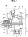
- a four-wheel-drive vehicle 100 includes a vehicle body 101, an engine 102, which serves as a drive source that generates torque for causing the four-wheel-drive vehicle 100 to travel, a transmission 103, right and left front wheels 104b, 104a, which serve as a pair of right and left main drive wheels to which driving force is always transmitted from the engine 102, and right and left rear wheels 105b, 105a, which serve as a pair of right and left auxiliary drive wheels to which the driving force is transmitted from the engine 102 depending on a travelling state.
- the four-wheel-drive vehicle 100 includes a front differential 106, a propeller shaft 107, and a driving force transmission apparatus 1, which constitute a driving force transmission system.
- the driving force which is output from the engine 102 and of which the speed is changed by the transmission 103, is always transmitted to the right and left front wheels 104b, 104a via the front differential 106 and a pair of drive shafts 106b, 106a.
- the right and left front wheels 104b, 104a function as steered wheels that are turned with respect to the vehicle body 101 in response to an operation of a steering wheel 109 performed by a driver.
- the driving force which is output from the engine 102 and of which the speed is changed by the transmission 103, is transmitted to the right and left rear wheels 105b, 105a via the propeller shaft 107, the driving force transmission apparatus 1, and a pair of drive shafts 108b, 108a.
- the driving force transmission apparatus 1 is able to adjust the driving force that is transmitted to the right rear wheel 105b and the driving force that is transmitted to the left rear wheel 105a independently from each other.
- the configuration of the driving force transmission apparatus 1 will be described later.
- the four-wheel-drive vehicle 100 includes a driving force control apparatus 10 that controls the driving force for the right rear wheel 105b and the driving force for the left rear wheel 105a independently from each other, with the use of the driving force transmission apparatus 1.
- the driving force control apparatus 10 includes a turning radius estimating unit 11, a target slip angle computing unit 12, a target rotational speed computing unit 13, and a driving force control unit 14. The driving force control apparatus 10 will be described later in detail.
- Rotational speed sensors 152, 151, 154, 153 that respectively detect rotational speeds of the right and left front wheels 104b, 104a and the right and left rear wheels 105b, 105a are connected to the driving force control apparatus 10.
- the rotational speed sensors 151 to 154 are each formed of, for example, a Hall IC that is arranged so as to face a magnetic ring that has a plurality of magnetic poles and that rotates together with a corresponding one of the right and left front wheels 104b, 104a, the right and left rear wheels 105b, 105a.
- the rotational speed sensors 15a to 15d each output a pulse signal with a period that corresponds to the rotational speed of a corresponding one of the right and left front wheels 104b, 104a and the right and left rear wheels 105b, 105a.
- the driving force control apparatus 10 is able to detect the rotational speeds of the right and left front wheels 104b, 104a and the right and left rear wheels 105b, 105a.
- a steering angle sensor 155 that detects a steering angle, which is a rotation angle of the steering wheel 109 from a neutral position, is connected to the driving force control apparatus 10. On the basis of a signal from the steering angle sensor 155, the driving force control apparatus 10 is able to detect the steering angle of the steering wheel 109.
- An accelerator operation amount sensor 156 that detects a depressed amount of an accelerator pedal 110 is connected to the driving force control apparatus 10. On the basis of a signal from the accelerator operation amount sensor 156, the driving force control apparatus 10 is able to detect the accelerator operation amount corresponding to the depressed amount of the accelerator pedal 110.
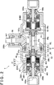
- FIG. 2 is a sectional view illustrating an example of the configuration of the driving force transmission apparatus 1.
- the driving force transmission apparatus 1 includes: a case member 20 having therein a first housing space 20a, a second housing space 20b, and a third housing space 20c; an input rotary member 3 housed in the first housing space 20a of the case member 20; and a pair of torque couplings 4 housed respectively in the second and the third housing spaces 20b, 20c, which are arranged on the opposite sides of the first housing space 20a.
- the torque coupling 4 housed in the second housing space 20b and the torque coupling 4 housed in the third housing space 20c have the same configuration. However, if it is necessary to distinguish the torque couplings 4 from each other in the following description, the torque coupling 4 housed in the second housing space 20b will be referred to as a first torque coupling 4A and the torque coupling 4 housed in the third housing space 20c will be referred to as a second torque coupling 4B.
- a pair of partitions 21 is provided.
- One of the partitions 21 separates the first housing space 20a and the second housing space 20b from each other, and the other one of the partitions 21 separates the first housing space 20a and the third housing space 20c from each other.
- Each of the partitions 21 has a through-hole 21a.
- the through-hole 21a of one of the partitions 21 provides communication between the first housing space 20a and the second housing space 20b, and the through-hole 21a of the other one of the partitions 21 provides communication between the first housing space 20a and the third housing space 20c.
- the input rotary member 3 has a first member 31 rotatably supported by the case member 20, and a second member 32 formed of an annular ring gear.
- the first member 31 and the second member 32 are connected to each other with a plurality of bolts 33.
- the first member 31 has a cylindrical portion 311 with a through-hole 31a formed at the center thereof, and a flange 312 that projects outward from the outer periphery of the cylindrical portion 311.
- the cylindrical portion 311 and the flange 312 are formed as a single-piece member.
- the second member 32 is fixed to a distal end portion of the flange 312 and meshes with a gear portion 107a formed at one end of the propeller shaft 107, which passes through a first opening 200a of the case member 20.
- the first member 31 is rotatably supported by a pair of bearings 22 disposed between the first member 31 and inner faces of the through-holes 21a.
- Each of the torque couplings 4 includes a multi-disc clutch 41, an electromagnetic clutch 42, a cam mechanism 43, an inner shaft 44, and a housing 40 that houses these components.
- the housing 40 is formed of a first housing member 401 and a second housing member 402 that are coupled to each other so as to be non-rotatable relative to each other.
- the first housing member 401 has a bottomed cylindrical shape, and the second housing member 402 is arranged so as to close an opening-side end portion of the first housing member 401.
- the multiple-disc clutch 41 is arranged between the first housing member 401 of the housing 40 and the cylindrical inner shaft 44.
- the multiple-disc clutch 41 includes inner clutch plates 411 and outer clutch plates 412.
- the inner clutch plates 411 are spline-engaged with the outer periphery of the inner shaft 44 so as to be non-rotatable relative to the inner shaft 44.
- the outer clutch plates 412 are spline-engaged with the inner periphery of the first housing member 401 so as to be non-rotatable relative to the first housing member 401.
- the electromagnetic clutch 42 includes an annular coil 421 and an armature cam 422, and is arranged on the rotational axis of the housing 40.
- the armature cam 422 is moved toward the coil 421 by an electromagnetic force generated by the coil 421.
- the armature cam 422 is brought into friction sliding with the second housing member 402.
- the cam mechanism 43 includes the armature cam 422, a main cam 431 and spherical cam followers 432.
- the armature cam 422 serves as a cam member.
- the main cam 431 is arranged next to the armature cam 422 along the rotational axis of the housing 40.
- the cam followers 432 are interposed between the main cam 431 and the armature cam 422.
- the armature cam 422 receives a rotational force from the housing 40 upon energization of the coil 421, and converts the rotational force into a pressing force that is used as a clutch force of the multiple-disc clutch 41.
- the torque coupling 4 is able to variably control the pressing force of the multiple-disc clutch 41 on the basis of the amount of electricity that is supplied to the coil 421, thereby adjusting the amount of torque that is transmitted between the housing 40 and the inner shaft 44.
- One end of the left rear wheel-side drive shaft 108a which is passed through a second opening 200b of the case member 20, is connected by spline-fitting to the inner shaft 44 of the first torque coupling 4A so as to be non-rotatable relative to the inner shaft 44.
- One end of the right rear wheel-side drive shaft 108b which is passed through a third opening 200c of the case member 20, is connected by spline-fitting to the inner shaft 44 of the second torque coupling 4B so as to be non-rotatable relative to the inner shaft 44.
- the housings 40 of the first torque coupling 4A and the second torque coupling 4B and the cylindrical portion 311 of the first member 31 of the input rotary member 3 are connected to each other by a pair of connecting members 50 so as to be non-rotatable relative to each other.
- Each of the connecting members 50 has a columnar boss portion 51 and a disc-shaped flange 52, which are formed as a single-piece member.
- the boss portion 51 is spline-fitted to the inner face of the through-hole 31a of the first member 31 so as to be non-rotatable relative to the first member 31, and the flange 52 is spline-fitted to the housing 40 so as to be non-rotatable relative to the housing 40.
- the boss portion 51 is passed through the through-hole 21a of the partition 21.
- Excitation current is supplied from the driving force control apparatus 10 to the coil 421 of the torque coupling 4.
- the driving force control apparatus 10 is able to control the driving force that is transmitted from the input rotary member 3 to the left rear wheel 105a by increasing or decreasing the current that is supplied to the coil 421 of the first torque coupling 4A.
- the driving force control apparatus 10 is able to control the driving force that is transmitted from the input rotary member 3 to the right rear wheel 105b by increasing or decreasing the current that is supplied to the coil 421 of the second torque coupling 4B.
- the gear ratio of each component is set such that the rotational speed of the right and left rear wheels 105b, 105a is higher than the rotational speed of the right and left front wheels 104b, 104a during straight-ahead travelling in which the inner clutch plates 411 and the outer clutch plates 412 of the multi-disc clutch 41 of each torque coupling 4 are completely frictionally engaged with each other without rotating relative to each other.
- the driving force control apparatus 10 includes, for example, a central processing unit (CPU) and a memory element.
- CPU central processing unit
- the driving force control apparatus 10 functions as the turning radius estimating unit 11, the target slip angle computing unit 12, the target rotational speed computing unit 13, and the driving force control unit 14.
- the turning radius estimating unit 11 estimates a turning radius of the four-wheel-drive vehicle 100.
- the turning radius is an ideal turning radius intended by the driver, and is, for example, a turning radius that conforms to the curvature of a curve of a road on which the four-wheel-drive vehicle 100 is travelling.
- the turning radius can be estimated on the basis of, for example, the steering angle of the steering wheel 109 detected by the steering angle sensor 155.
- the turning radius may be estimated on the basis of, for example, an image captured by an in-vehicle camera, or the turning radius may be estimated on the basis of map information and the information on a present location obtained from a car navigation system or the like.
- the target slip angle computing unit 12 computes a target slip angle at the time of turning of the four-wheel-drive vehicle 100, on the basis of the turning radius estimated by the turning radius estimating unit 11.
- the slip angle in this case refers to an angle formed by the central axis that extends along the longitudinal direction of the four-wheel-drive vehicle 100 (the direction orthogonal to the vehicle width direction), and the actual travelling direction of the four-wheel-drive vehicle 100.
- the target slip angle refers to a suitable slip angle at which the four-wheel-drive vehicle 100 is able to travel along the arc of a turning radius estimated by the turning radius estimating unit 11.
- the target slip angle can be obtained by computation on the basis of, for example, a vehicle speed and an accelerator operation amount.
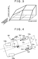
- FIG. 3 is an example of a map illustrating the relationship among a vehicle speed, an accelerator operation amount, and a target slip angle.
- the target slip angle computing unit 12 refers to the map, and sets the target slip angle to a larger value as the vehicle speed is higher and as the accelerator operation amount is larger. In other words, if the vehicle speed is high or the accelerator operation amount is large and therefore the wheels are likely to slip, the four-wheel-drive vehicle 100 travels while being oriented further inward (oriented toward the center of turn) with respect to the actual traveling direction, that is, the four-wheel-drive vehicle 100 is countersteered.
- the target slip angle computing unit 12 stores a plurality of maps each indicating the relationship among a vehicle speed, an accelerator operation amount, and a target slip angle, and refers to one of the maps according to the turning radius estimated by the turning radius estimating unit 11 to compute a target slip angle.
- the target slip angle computing unit 12 may set the target slip angle by executing computation based on a friction coefficient of a road surface. In this case, the lower the friction coefficient of the road surface is, the larger the target slip angle is.
- the target slip angle obtained on the basis of the vehicle speed and the accelerator operation amount may be corrected according to the friction coefficient of the road surface. In this case, the correction is made such that the lower the friction coefficient of the road surface is, the larger the target slip angle is. Further, the target slip angle may be set or corrected on the basis of a centrifugal force that acts on the four-wheel-drive vehicle 100.
- the target rotational speed computing unit 13 computes the target rotational speeds of the right and left rear wheels 105b, 105a on the basis of the turning radius estimated by the turning radius estimating unit 11, the target slip angle computed by the target slip angle computing unit 12, and the vehicle speed.
- the target rotational speeds in this case mean the rotational speeds of wheels in the case where the four-wheel-drive vehicle 100 travels at the turning radius estimated by the turning radius estimating unit 11 and at the target slip angle computed by the target slip angle computing unit 12, at the actual vehicle speed of the four-wheel-drive vehicle 100 determined on the basis of the rotational speeds of the right and left front wheels 104b, 104a and the right and left rear wheels 105b, 105a.
- FIG. 4 is an explanatory diagram illustrating an example of computation of target rotational speeds of right and left rear wheels 105b, 105a.
- a dashed line indicated by C denotes the central axis of the four-wheel-drive vehicle 100
- a two-dot chain line indicated by D denotes an arc-shaped trajectory of the turning radius estimated by the turning radius estimating unit 11 (an ideal travelling direction of the four-wheel-drive vehicle 100).
- a tread width which is the center-to-center distance between the right and left rear wheels 105b, 105a, is denoted by W, and it is assumed that the right rear wheel 105b is on the outer side of a turn, that is, the left rear wheel 105a is on the inner side of the turn.
- the travelling direction of the four-wheel-drive vehicle 100 is denoted by a vector VI
- the rolling direction of the left rear wheel 105a is denoted by a vector Va1
- the rolling direction of the right rear wheel 105b is denoted by a vector Vb1.
- the length of the vector Va1 represents the rotational speed of the left rear wheel 105a
- the length of the vector Vb1 represents the rotational speed of the right rear wheel 105b.
- the angle formed by the vector V1 and the central axis C is a slip angle ⁇ .
- the turning radius estimated by the turning radius estimating unit 11 is denoted by R
- the vehicle speed is denoted by V
- the yaw rate is denoted by ⁇
- the target rotational speed computing unit 13 is able to convert the vector lengths La, Lb into the target rotational speeds of the right and left rear wheels 105b, 105a, by taking the diameters of the right and left rear wheels 105b, 105a into account.
- the driving force control unit 14 controls the driving force that is transmitted to the right rear wheel 105b and the driving force that is transmitted to the left rear wheel 105a such that the actual rotational speeds of the right rear wheel 105b and the left rear wheel 105a approach the target rotational speeds computed by the target rotational speed computing unit 13.
- the current that is supplied to the coil 421 of the first torque coupling 4A is increased to increase the rotational speed of the left rear wheel 105a. If the actual rotational speed of the left rear wheel 105a is higher than the target rotational speed of the left rear wheel 105a, the current that is supplied to the coil 421 of the first torque coupling 4A is decreased to reduce the rotational speed of the left rear wheel 105a.
- the current that is supplied to the coil 421 of the second torque coupling 4B is increased or decreased to control the driving force that is transmitted to the right rear wheel 105b such that the actual rotational speed of the right rear wheel 105b approaches the target rotational speed of the right rear wheel 105b.
- the driving force control unit 14 inverts the magnitude relationship between the amount of torque that is transmitted between the input rotary member 3 and the left rear wheel 105a by the first torque coupling 4A and the amount of torque that is transmitted between the input rotary member 3 and the right rear wheel 105b.
- the depressed amount of the accelerator pedal 110 is reduced and the engine braking occurs, it is possible to execute a control such that the actual rotational speeds of the right rear wheel 105b and the left rear wheel 105a approach the target rotational speeds.
- the driving force that is transmitted to the right rear wheel 105b and the driving force that is transmitted to the left rear wheel 105a are controlled such that the four-wheel-drive vehicle 100 travels along the trajectory of the estimated turning radius.
- the four-wheel-drive vehicle 100 is allowed to travel along the target turning radius. That is, it is possible to achieve stable turning performance.
- the driving force control apparatus for a four-wheel-drive vehicle has been described with reference to the embodiment.
- the invention is not limited to the embodiment, and may be implemented in various other embodiments within the scope of the invention.
- the configuration of the driving force transmission apparatus 1 is not limited to the one illustrated in FIG. 2 , and various other configurations may be employed.
- the four-wheel-drive vehicle 100 includes the engine 102 that serves as a single drive source.
- the four-wheel-drive vehicle 100 may include a plurality of drive sources. More specifically, electric motors that serve as drive sources may be provided for the right and left front wheels 104b, 104a and the right and left rear wheels 105b, 105a, respectively.
- the driving force control apparatus 10 controls the driving forces for the right and left rear wheels 105b, 105a.
- the driving force control apparatus 10 may control the driving forces for the right and left front wheels 104b, 104a, or may control the driving forces for the right and left front wheels 104b, 104a and the right and left rear wheels 105b, 105a.
- the configuration of a vehicle drive system is not particularly limited, and the invention may be applicable to, for example, a two-wheel-drive vehicle.
- a driving force control apparatus includes: a turning radius estimating unit that estimates a turning radius of a four-wheel-drive vehicle; a target slip angle computing unit that computes a target slip angle at the time of turning of the four-wheel-drive vehicle, on the basis of the estimated turning radius; a target rotational speed computing unit that computes target rotational speeds of right and left rear wheels of the four-wheel-drive vehicle, on the basis of the estimated turning radius, the computed target slip angle, and a vehicle speed; and a driving force control unit that controls driving forces that are transmitted to the right and left rear wheels such that actual rotational speeds of the right and left rear wheels approach the computed target rotational speeds.
Landscapes
- Engineering & Computer Science (AREA)
- Transportation (AREA)
- Mechanical Engineering (AREA)
- Chemical & Material Sciences (AREA)
- Combustion & Propulsion (AREA)
- Automation & Control Theory (AREA)
- Physics & Mathematics (AREA)
- Theoretical Computer Science (AREA)
- Databases & Information Systems (AREA)
- Mathematical Physics (AREA)
- Software Systems (AREA)
- General Engineering & Computer Science (AREA)
- General Physics & Mathematics (AREA)
- Data Mining & Analysis (AREA)
- Arrangement And Driving Of Transmission Devices (AREA)
- Retarders (AREA)
Claims (3)
- Antriebskraftsteuervorrichtung (10), mit:einer Drehradiusschätzeinheit (11), die einen Drehradius eines Fahrzeugs (100) schätzt; undeiner Sollrutschwinkelberechnungseinheit (12), die einen Sollrutschwinkel zu der Zeit des Drehens des Fahrzeugs (100) ausgehend von dem geschätzten Drehradius berechnet;gekennzeichnet durcheine Solldrehzahlberechnungseinheit (13), die Solldrehzahlen von rechten und linken Rädern (104b, 104a; 105b, 105a) an zumindest einer Vorderradseite und einer Hinterradseite ausgehend von dem geschätzten Drehradius, dem berechneten Sollrutschwinkel und einer Fahrzeuggeschwindigkeit berechnet; undeiner Antriebskraftsteuereinheit (14), die Antriebskräfte für die rechten und linken Räder (104b, 104a; 105b, 105a) derart steuert, dass tatsächliche Drehzahlen der rechten und linken Räder (104b, 104a; 105b, 105a) sich den berechneten Solldrehzahlen annähern,wobeidie Antriebskraftsteuereinheit (14) konfiguriert ist, eine Größe des Moments anzupassen, das zwischen einem Eingabedrehelement (3), zu dem die Antriebskraft von einer Antriebsquelle (102) übertragen wird, und dem rechten Rad (104b; 105b) übertragen wird, und eine Größe eines Moments, das zwischen dem Eingabedrehelement (3) und dem linken Rad (104a; 105a) übertragen wird, um die Antriebskraft für das rechte Rad (104b; 105b) und die Antriebskraft für das linke Rad (104a; 105a) zu steuern; undwährend des Bremsens, in dem das Moment zu dem Eingabedrehelement (3) von dem rechten Rad (104b; 105b) und dem linken Rad (104a; 105a) übertragen wird, die Antriebskraftsteuereinheit (14) ein Größenordnungsverhältnis zwischen der Größe des zwischen dem Eingabedrehelement (3) und dem rechten Rad (104b; 105b) übertragenen Moments und der Größe des zwischen dem Eingabedrehelement (3) und dem linken Rad (104a; 105a) übertragenen Moments umkehrt.
- Antriebskraftsteuervorrichtung (10) nach Anspruch 1, wobei
die Antriebskraftsteuereinheit (14) die Antriebskraft für ein rechtes Rad (104b; 105b) und die Antriebskraft für ein linkes Rad (104a; 105a) unabhängig voneinander steuert, wobei das rechte Rad (104b; 105b) und das linke Rad (104a; 105a) auf einer Seite unter der Vorderradseite und der Hinterradseite liegen, und die Übertragung der Antriebskraft von einer Antriebsquelle (102) zu der einen Seite ausgewählt ermöglicht und unterbrochen wird. - Fahrzeugsteuerverfahren mit den Schritten:Schätzen eines Drehradius eines Fahrzeugs;Berechnen eines Sollrutschwinkels zu der Zeit des Drehens des Fahrzeugs ausgehend von dem geschätzten Drehradius;gekennzeichnet durchBerechnen von Solldrehzahlen von rechten und linken Rädern (104b, 105b; 104a, 105a) von zumindest einer aus einer Vorderradseite und einer Hinterradseite ausgehend von dem geschätzten Drehradius, dem berechneten Sollrutschwinkel und einer Fahrzeuggeschwindigkeit (V);Steuern von Antriebskräften für die rechten (104b; 105b) und linken Räder (104a; 105a), derart, dass tatsächliche Drehzahlen der rechten und linken Räder (104b, 105b; 104a, 105a) sich den berechneten Solldrehzahlen annähern,Anpassen einer Größe eines Moments, das zwischen einem Eingabedrehelement (3), zu dem die Antriebskraft von einer Antriebsquelle (102) übertragen wird, und dem rechten Rad (104b; 105b) übertragen wird, und einer Größe eines Moments, das zwischen dem Eingabedrehelement (3) und dem linken Rad (104a; 105a) übertragen wird, anzupassen, um die Antriebskraft für das rechte Rad (104b; 105b) und die Antriebskraft für das linke Rad (104a; 105a) zu steuern; undwährend des Bremsens, in dem ein Moment zu dem Eingabedrehelement (3) von dem rechten Rad (104b; 105b) und dem linken Rad (104a; 105a) übertragen wird, ein Größenordnungsverhältnis zwischen der Größe des zwischen dem Eingabedrehelement (3) und dem rechten Rad (104b; 105b) übertragenen Moments und der Größe des zwischen dem Eingabedrehelement (3) und dem linken Rad (104a; 105a) übertragenen Moments umgekehrt wird.
Applications Claiming Priority (1)
| Application Number | Priority Date | Filing Date | Title |
|---|---|---|---|
| JP2012182366A JP5971027B2 (ja) | 2012-08-21 | 2012-08-21 | 駆動力制御装置及び車両の制御方法 |
Publications (3)
| Publication Number | Publication Date |
|---|---|
| EP2700551A2 EP2700551A2 (de) | 2014-02-26 |
| EP2700551A3 EP2700551A3 (de) | 2018-04-25 |
| EP2700551B1 true EP2700551B1 (de) | 2020-04-29 |
Family
ID=49000309
Family Applications (1)
| Application Number | Title | Priority Date | Filing Date |
|---|---|---|---|
| EP13180342.1A Active EP2700551B1 (de) | 2012-08-21 | 2013-08-14 | Antriebskraftsteuerungsvorrichtung und Fahrzeugsteuerungsverfahren |
Country Status (4)
| Country | Link |
|---|---|
| US (1) | US8886436B2 (de) |
| EP (1) | EP2700551B1 (de) |
| JP (1) | JP5971027B2 (de) |
| CN (1) | CN103625465B (de) |
Families Citing this family (21)
| Publication number | Priority date | Publication date | Assignee | Title |
|---|---|---|---|---|
| JP5668746B2 (ja) * | 2012-12-26 | 2015-02-12 | トヨタ自動車株式会社 | 車両の制御装置 |
| JP5907142B2 (ja) * | 2013-10-22 | 2016-04-20 | トヨタ自動車株式会社 | 四輪駆動車両の制御装置 |
| GB2522442A (en) * | 2014-01-24 | 2015-07-29 | Jaguar Land Rover Ltd | Driveline and method of controlling a driveline |
| GB2534117B (en) | 2014-11-19 | 2018-09-12 | Jaguar Land Rover Ltd | Control system and method of controlling a driveline |
| CN106314426B (zh) * | 2015-07-10 | 2019-01-11 | 比亚迪股份有限公司 | 用于四轮独立驱动的汽车的转弯控制方法及系统 |
| US9657826B1 (en) * | 2016-08-17 | 2017-05-23 | Borgwarner Inc. | Electric motor with coaxial clutch packs that provide differential and torque vectoring |
| JP6787060B2 (ja) | 2016-11-11 | 2020-11-18 | 株式会社ジェイテクト | 駆動力制御装置及び車両の制御方法 |
| CN107199884B (zh) * | 2017-05-08 | 2019-11-15 | 吉林大学 | 用于减小车轴平均滑转率的转矩分配方法 |
| JP6988267B2 (ja) * | 2017-08-28 | 2022-01-05 | 株式会社ジェイテクト | 駆動力制御装置及び車両の制御方法 |
| JP7234586B2 (ja) * | 2018-11-07 | 2023-03-08 | 株式会社ジェイテクト | 駆動力制御装置、駆動装置、及び駆動力伝達装置 |
| FR3092793B1 (fr) * | 2019-02-15 | 2021-01-29 | Valeo Embrayages | Dispositif de transmission de couple pour un véhicule automobile |
| US11167638B2 (en) * | 2019-08-29 | 2021-11-09 | Kawasaki Jukogyo Kabushiki Kaisha | Utility vehicle |
| CA3175561A1 (en) | 2020-04-17 | 2021-10-21 | Polaris Industries Inc. | Torque vectoring for utility vehicles |
| CN114347964A (zh) * | 2022-03-18 | 2022-04-15 | 所托(杭州)汽车智能设备有限公司 | 车辆辅助控制方法、装置及汽车 |
| WO2023194760A1 (ja) * | 2022-04-05 | 2023-10-12 | 日産自動車株式会社 | 走行支援方法及び走行支援装置 |
| CN116080417A (zh) * | 2023-02-03 | 2023-05-09 | 湖南三一中益机械有限公司 | 工程车辆的驱动方法、装置及工程车辆 |
| US12459493B2 (en) * | 2023-02-16 | 2025-11-04 | Ford Global Technologies, Llc | System and method for brake assisted vehicle turning radius reduction |
| CN116946247B (zh) * | 2023-09-20 | 2024-04-02 | 博世汽车部件(苏州)有限公司 | 车辆转向辅助系统及其控制单元 |
| CN116946245B (zh) * | 2023-09-20 | 2023-11-28 | 博世汽车部件(苏州)有限公司 | 车辆转向辅助系统及其控制单元 |
| DE102024129385A1 (de) | 2024-10-11 | 2026-04-16 | Voith Patent Gmbh | Lagerbock zum Anlenken einer Kupplungsstange an einem Wagenkasten eines mehrgliedrigen Fahrzeugs und Schienenfahrzeug |
| CN121739070A (zh) * | 2026-03-02 | 2026-03-27 | 浙江杰西嘉传动有限公司 | 传动机构及使用该传动机构的全地形车 |
Citations (1)
| Publication number | Priority date | Publication date | Assignee | Title |
|---|---|---|---|---|
| US20060048976A1 (en) * | 2004-09-06 | 2006-03-09 | Nissan Motor Co., Ltd. | Electric vehicle |
Family Cites Families (26)
| Publication number | Priority date | Publication date | Assignee | Title |
|---|---|---|---|---|
| JP2833199B2 (ja) * | 1990-11-20 | 1998-12-09 | 日産自動車株式会社 | トルク配分制御装置 |
| JP2776123B2 (ja) | 1992-03-19 | 1998-07-16 | 三菱自動車工業株式会社 | 車両用左右駆動力制御装置 |
| JPH05319124A (ja) * | 1992-05-26 | 1993-12-03 | Mazda Motor Corp | 4輪駆動車の走行制御装置 |
| JP3268124B2 (ja) * | 1994-06-27 | 2002-03-25 | 富士重工業株式会社 | 車両のトルク配分制御装置 |
| DE69722562T2 (de) * | 1996-07-24 | 2004-05-06 | Denso Corp., Kariya | Regelsystem für einen Fahrzeugbewegungszustand |
| JP4129702B2 (ja) * | 1997-07-11 | 2008-08-06 | マツダ株式会社 | 車両の姿勢制御装置 |
| JPH1159216A (ja) * | 1997-08-26 | 1999-03-02 | Fuji Heavy Ind Ltd | 4輪駆動車の動力配分制御装置 |
| JP2000203298A (ja) * | 1999-01-19 | 2000-07-25 | Unisia Jecs Corp | 車両制御装置 |
| JP2001010474A (ja) * | 1999-06-30 | 2001-01-16 | Aisin Seiki Co Ltd | 車両の運動制御装置 |
| JP3960740B2 (ja) * | 2000-07-31 | 2007-08-15 | トヨタ自動車株式会社 | 車両の制動制御装置 |
| JP2002104155A (ja) * | 2000-09-29 | 2002-04-10 | Aisin Seiki Co Ltd | 車両の運動制御装置 |
| JP3878840B2 (ja) * | 2001-11-27 | 2007-02-07 | トヨタ自動車株式会社 | 車輌の走行制御装置 |
| JP4254512B2 (ja) * | 2003-12-05 | 2009-04-15 | トヨタ自動車株式会社 | 自動車およびその制御方法 |
| US7970512B2 (en) * | 2006-08-30 | 2011-06-28 | Ford Global Technologies | Integrated control system for stability control of yaw, roll and lateral motion of a driving vehicle using an integrated sensing system with pitch information |
| US8321088B2 (en) * | 2006-08-30 | 2012-11-27 | Ford Global Technologies | Integrated control system for stability control of yaw, roll and lateral motion of a driving vehicle using an integrated sensing system to determine lateral velocity |
| JP4270259B2 (ja) * | 2006-10-05 | 2009-05-27 | 日産自動車株式会社 | 障害物回避制御装置 |
| JP4636012B2 (ja) * | 2006-12-11 | 2011-02-23 | トヨタ自動車株式会社 | 車両の制動制御装置 |
| JP4594346B2 (ja) * | 2007-03-22 | 2010-12-08 | トヨタ自動車株式会社 | 車両挙動制御装置 |
| JP2009035081A (ja) * | 2007-07-31 | 2009-02-19 | Equos Research Co Ltd | 制御装置 |
| JP5082694B2 (ja) * | 2007-09-05 | 2012-11-28 | トヨタ自動車株式会社 | 車両の駆動力配分制御装置 |
| JP4315226B2 (ja) * | 2007-11-09 | 2009-08-19 | トヨタ自動車株式会社 | 駆動力制御装置 |
| JP4994212B2 (ja) | 2007-12-20 | 2012-08-08 | Gknドライブラインジャパン株式会社 | 駆動力分配伝達装置 |
| US9139173B2 (en) * | 2008-10-28 | 2015-09-22 | Advics Co., Ltd. | Device for controlling traveling of vehicle |
| JP4842335B2 (ja) * | 2009-02-12 | 2011-12-21 | 日立建機株式会社 | 電動車両の旋回補助装置 |
| JP5257414B2 (ja) * | 2010-07-09 | 2013-08-07 | 日産自動車株式会社 | 四輪駆動車両の駆動力配分制御装置 |
| EP2611662B1 (de) * | 2010-08-30 | 2016-09-21 | e-AAM Driveline Systems AB | Verfahren zur steuerung eines drehmomentvektorisierungsmechanismus und drehmomentvektorisierungssystem |
-
2012
- 2012-08-21 JP JP2012182366A patent/JP5971027B2/ja active Active
-
2013
- 2013-08-08 US US13/962,049 patent/US8886436B2/en active Active
- 2013-08-09 CN CN201310346708.8A patent/CN103625465B/zh active Active
- 2013-08-14 EP EP13180342.1A patent/EP2700551B1/de active Active
Patent Citations (1)
| Publication number | Priority date | Publication date | Assignee | Title |
|---|---|---|---|---|
| US20060048976A1 (en) * | 2004-09-06 | 2006-03-09 | Nissan Motor Co., Ltd. | Electric vehicle |
Also Published As
| Publication number | Publication date |
|---|---|
| CN103625465A (zh) | 2014-03-12 |
| US8886436B2 (en) | 2014-11-11 |
| US20140058643A1 (en) | 2014-02-27 |
| EP2700551A3 (de) | 2018-04-25 |
| JP2014040852A (ja) | 2014-03-06 |
| JP5971027B2 (ja) | 2016-08-17 |
| CN103625465B (zh) | 2017-06-09 |
| EP2700551A2 (de) | 2014-02-26 |
Similar Documents
| Publication | Publication Date | Title |
|---|---|---|
| EP2700551B1 (de) | Antriebskraftsteuerungsvorrichtung und Fahrzeugsteuerungsverfahren | |
| US9266522B2 (en) | Driving force transmission controller and vehicle control method | |
| US10493845B2 (en) | Drive force control device and method of controlling vehicle | |
| US8989964B2 (en) | Vehicle speed control device | |
| US20020003057A1 (en) | Drive-force distribution controller | |
| JPH01145229A (ja) | 四輪駆動車の駆動力配分制御装置 | |
| US9561720B2 (en) | Driving force distribution control apparatus | |
| CN107891744A (zh) | 驱动力传递装置的控制装置 | |
| US10994725B2 (en) | Four-wheel-drive vehicle | |
| JP2007106399A (ja) | トルク配分制御システム | |
| CN109421700B (zh) | 驱动力控制装置及车辆的控制方法 | |
| US8594889B2 (en) | Inclination controlling method using torque vectoring system | |
| US11970170B2 (en) | Controlling a drive system for an axle of a motor vehicle | |
| WO2020240953A1 (ja) | 車両の制御システム | |
| JP6141751B2 (ja) | 駆動力配分制御装置 | |
| JP5458901B2 (ja) | 4輪駆動車の駆動力配分制御装置 | |
| JPH0635259B2 (ja) | 車両用駆動系クラツチ制御装置 | |
| JP2012017054A (ja) | 車両の左右輪駆動力配分制御装置 | |
| JP2005306273A (ja) | 車両駆動システム | |
| JP7020884B2 (ja) | 電磁式アクチュエータ | |
| JP6164428B2 (ja) | 四輪駆動車のスリップ率制御装置 | |
| JP2021126960A (ja) | 4輪駆動車の制御装置 | |
| JPS6378822A (ja) | 車両用駆動系クラツチ制御装置 |
Legal Events
| Date | Code | Title | Description |
|---|---|---|---|
| PUAI | Public reference made under article 153(3) epc to a published international application that has entered the european phase |
Free format text: ORIGINAL CODE: 0009012 |
|
| AK | Designated contracting states |
Kind code of ref document: A2 Designated state(s): AL AT BE BG CH CY CZ DE DK EE ES FI FR GB GR HR HU IE IS IT LI LT LU LV MC MK MT NL NO PL PT RO RS SE SI SK SM TR |
|
| AX | Request for extension of the european patent |
Extension state: BA ME |
|
| PUAL | Search report despatched |
Free format text: ORIGINAL CODE: 0009013 |
|
| AK | Designated contracting states |
Kind code of ref document: A3 Designated state(s): AL AT BE BG CH CY CZ DE DK EE ES FI FR GB GR HR HU IE IS IT LI LT LU LV MC MK MT NL NO PL PT RO RS SE SI SK SM TR |
|
| AX | Request for extension of the european patent |
Extension state: BA ME |
|
| RIC1 | Information provided on ipc code assigned before grant |
Ipc: B60W 40/072 20120101ALI20180316BHEP Ipc: B60W 30/045 20120101AFI20180316BHEP |
|
| STAA | Information on the status of an ep patent application or granted ep patent |
Free format text: STATUS: REQUEST FOR EXAMINATION WAS MADE |
|
| 17P | Request for examination filed |
Effective date: 20181019 |
|
| STAA | Information on the status of an ep patent application or granted ep patent |
Free format text: STATUS: EXAMINATION IS IN PROGRESS |
|
| 17Q | First examination report despatched |
Effective date: 20190430 |
|
| GRAP | Despatch of communication of intention to grant a patent |
Free format text: ORIGINAL CODE: EPIDOSNIGR1 |
|
| STAA | Information on the status of an ep patent application or granted ep patent |
Free format text: STATUS: GRANT OF PATENT IS INTENDED |
|
| INTG | Intention to grant announced |
Effective date: 20191129 |
|
| GRAS | Grant fee paid |
Free format text: ORIGINAL CODE: EPIDOSNIGR3 |
|
| GRAA | (expected) grant |
Free format text: ORIGINAL CODE: 0009210 |
|
| STAA | Information on the status of an ep patent application or granted ep patent |
Free format text: STATUS: THE PATENT HAS BEEN GRANTED |
|
| AK | Designated contracting states |
Kind code of ref document: B1 Designated state(s): AL AT BE BG CH CY CZ DE DK EE ES FI FR GB GR HR HU IE IS IT LI LT LU LV MC MK MT NL NO PL PT RO RS SE SI SK SM TR |
|
| REG | Reference to a national code |
Ref country code: GB Ref legal event code: FG4D |
|
| REG | Reference to a national code |
Ref country code: CH Ref legal event code: EP |
|
| REG | Reference to a national code |
Ref country code: AT Ref legal event code: REF Ref document number: 1262856 Country of ref document: AT Kind code of ref document: T Effective date: 20200515 |
|
| REG | Reference to a national code |
Ref country code: DE Ref legal event code: R096 Ref document number: 602013068371 Country of ref document: DE |
|
| REG | Reference to a national code |
Ref country code: IE Ref legal event code: FG4D |
|
| REG | Reference to a national code |
Ref country code: NL Ref legal event code: MP Effective date: 20200429 |
|
| REG | Reference to a national code |
Ref country code: LT Ref legal event code: MG4D |
|
| PG25 | Lapsed in a contracting state [announced via postgrant information from national office to epo] |
Ref country code: IS Free format text: LAPSE BECAUSE OF FAILURE TO SUBMIT A TRANSLATION OF THE DESCRIPTION OR TO PAY THE FEE WITHIN THE PRESCRIBED TIME-LIMIT Effective date: 20200829 Ref country code: PT Free format text: LAPSE BECAUSE OF FAILURE TO SUBMIT A TRANSLATION OF THE DESCRIPTION OR TO PAY THE FEE WITHIN THE PRESCRIBED TIME-LIMIT Effective date: 20200831 Ref country code: NO Free format text: LAPSE BECAUSE OF FAILURE TO SUBMIT A TRANSLATION OF THE DESCRIPTION OR TO PAY THE FEE WITHIN THE PRESCRIBED TIME-LIMIT Effective date: 20200729 Ref country code: LT Free format text: LAPSE BECAUSE OF FAILURE TO SUBMIT A TRANSLATION OF THE DESCRIPTION OR TO PAY THE FEE WITHIN THE PRESCRIBED TIME-LIMIT Effective date: 20200429 Ref country code: SE Free format text: LAPSE BECAUSE OF FAILURE TO SUBMIT A TRANSLATION OF THE DESCRIPTION OR TO PAY THE FEE WITHIN THE PRESCRIBED TIME-LIMIT Effective date: 20200429 Ref country code: GR Free format text: LAPSE BECAUSE OF FAILURE TO SUBMIT A TRANSLATION OF THE DESCRIPTION OR TO PAY THE FEE WITHIN THE PRESCRIBED TIME-LIMIT Effective date: 20200730 Ref country code: FI Free format text: LAPSE BECAUSE OF FAILURE TO SUBMIT A TRANSLATION OF THE DESCRIPTION OR TO PAY THE FEE WITHIN THE PRESCRIBED TIME-LIMIT Effective date: 20200429 |
|
| REG | Reference to a national code |
Ref country code: AT Ref legal event code: MK05 Ref document number: 1262856 Country of ref document: AT Kind code of ref document: T Effective date: 20200429 |
|
| PG25 | Lapsed in a contracting state [announced via postgrant information from national office to epo] |
Ref country code: BG Free format text: LAPSE BECAUSE OF FAILURE TO SUBMIT A TRANSLATION OF THE DESCRIPTION OR TO PAY THE FEE WITHIN THE PRESCRIBED TIME-LIMIT Effective date: 20200729 Ref country code: HR Free format text: LAPSE BECAUSE OF FAILURE TO SUBMIT A TRANSLATION OF THE DESCRIPTION OR TO PAY THE FEE WITHIN THE PRESCRIBED TIME-LIMIT Effective date: 20200429 Ref country code: LV Free format text: LAPSE BECAUSE OF FAILURE TO SUBMIT A TRANSLATION OF THE DESCRIPTION OR TO PAY THE FEE WITHIN THE PRESCRIBED TIME-LIMIT Effective date: 20200429 Ref country code: RS Free format text: LAPSE BECAUSE OF FAILURE TO SUBMIT A TRANSLATION OF THE DESCRIPTION OR TO PAY THE FEE WITHIN THE PRESCRIBED TIME-LIMIT Effective date: 20200429 |
|
| PG25 | Lapsed in a contracting state [announced via postgrant information from national office to epo] |
Ref country code: AL Free format text: LAPSE BECAUSE OF FAILURE TO SUBMIT A TRANSLATION OF THE DESCRIPTION OR TO PAY THE FEE WITHIN THE PRESCRIBED TIME-LIMIT Effective date: 20200429 Ref country code: NL Free format text: LAPSE BECAUSE OF FAILURE TO SUBMIT A TRANSLATION OF THE DESCRIPTION OR TO PAY THE FEE WITHIN THE PRESCRIBED TIME-LIMIT Effective date: 20200429 |
|
| PG25 | Lapsed in a contracting state [announced via postgrant information from national office to epo] |
Ref country code: AT Free format text: LAPSE BECAUSE OF FAILURE TO SUBMIT A TRANSLATION OF THE DESCRIPTION OR TO PAY THE FEE WITHIN THE PRESCRIBED TIME-LIMIT Effective date: 20200429 Ref country code: ES Free format text: LAPSE BECAUSE OF FAILURE TO SUBMIT A TRANSLATION OF THE DESCRIPTION OR TO PAY THE FEE WITHIN THE PRESCRIBED TIME-LIMIT Effective date: 20200429 Ref country code: RO Free format text: LAPSE BECAUSE OF FAILURE TO SUBMIT A TRANSLATION OF THE DESCRIPTION OR TO PAY THE FEE WITHIN THE PRESCRIBED TIME-LIMIT Effective date: 20200429 Ref country code: IT Free format text: LAPSE BECAUSE OF FAILURE TO SUBMIT A TRANSLATION OF THE DESCRIPTION OR TO PAY THE FEE WITHIN THE PRESCRIBED TIME-LIMIT Effective date: 20200429 Ref country code: CZ Free format text: LAPSE BECAUSE OF FAILURE TO SUBMIT A TRANSLATION OF THE DESCRIPTION OR TO PAY THE FEE WITHIN THE PRESCRIBED TIME-LIMIT Effective date: 20200429 Ref country code: SM Free format text: LAPSE BECAUSE OF FAILURE TO SUBMIT A TRANSLATION OF THE DESCRIPTION OR TO PAY THE FEE WITHIN THE PRESCRIBED TIME-LIMIT Effective date: 20200429 Ref country code: EE Free format text: LAPSE BECAUSE OF FAILURE TO SUBMIT A TRANSLATION OF THE DESCRIPTION OR TO PAY THE FEE WITHIN THE PRESCRIBED TIME-LIMIT Effective date: 20200429 Ref country code: DK Free format text: LAPSE BECAUSE OF FAILURE TO SUBMIT A TRANSLATION OF THE DESCRIPTION OR TO PAY THE FEE WITHIN THE PRESCRIBED TIME-LIMIT Effective date: 20200429 |
|
| REG | Reference to a national code |
Ref country code: DE Ref legal event code: R097 Ref document number: 602013068371 Country of ref document: DE |
|
| PG25 | Lapsed in a contracting state [announced via postgrant information from national office to epo] |
Ref country code: SK Free format text: LAPSE BECAUSE OF FAILURE TO SUBMIT A TRANSLATION OF THE DESCRIPTION OR TO PAY THE FEE WITHIN THE PRESCRIBED TIME-LIMIT Effective date: 20200429 Ref country code: PL Free format text: LAPSE BECAUSE OF FAILURE TO SUBMIT A TRANSLATION OF THE DESCRIPTION OR TO PAY THE FEE WITHIN THE PRESCRIBED TIME-LIMIT Effective date: 20200429 |
|
| PLBE | No opposition filed within time limit |
Free format text: ORIGINAL CODE: 0009261 |
|
| STAA | Information on the status of an ep patent application or granted ep patent |
Free format text: STATUS: NO OPPOSITION FILED WITHIN TIME LIMIT |
|
| PG25 | Lapsed in a contracting state [announced via postgrant information from national office to epo] |
Ref country code: MC Free format text: LAPSE BECAUSE OF FAILURE TO SUBMIT A TRANSLATION OF THE DESCRIPTION OR TO PAY THE FEE WITHIN THE PRESCRIBED TIME-LIMIT Effective date: 20200429 |
|
| REG | Reference to a national code |
Ref country code: CH Ref legal event code: PL |
|
| 26N | No opposition filed |
Effective date: 20210201 |
|
| GBPC | Gb: european patent ceased through non-payment of renewal fee |
Effective date: 20200814 |
|
| PG25 | Lapsed in a contracting state [announced via postgrant information from national office to epo] |
Ref country code: LI Free format text: LAPSE BECAUSE OF NON-PAYMENT OF DUE FEES Effective date: 20200831 Ref country code: CH Free format text: LAPSE BECAUSE OF NON-PAYMENT OF DUE FEES Effective date: 20200831 Ref country code: LU Free format text: LAPSE BECAUSE OF NON-PAYMENT OF DUE FEES Effective date: 20200814 |
|
| REG | Reference to a national code |
Ref country code: BE Ref legal event code: MM Effective date: 20200831 |
|
| PG25 | Lapsed in a contracting state [announced via postgrant information from national office to epo] |
Ref country code: SI Free format text: LAPSE BECAUSE OF FAILURE TO SUBMIT A TRANSLATION OF THE DESCRIPTION OR TO PAY THE FEE WITHIN THE PRESCRIBED TIME-LIMIT Effective date: 20200429 |
|
| PG25 | Lapsed in a contracting state [announced via postgrant information from national office to epo] |
Ref country code: FR Free format text: LAPSE BECAUSE OF NON-PAYMENT OF DUE FEES Effective date: 20200831 |
|
| PG25 | Lapsed in a contracting state [announced via postgrant information from national office to epo] |
Ref country code: GB Free format text: LAPSE BECAUSE OF NON-PAYMENT OF DUE FEES Effective date: 20200814 Ref country code: IE Free format text: LAPSE BECAUSE OF NON-PAYMENT OF DUE FEES Effective date: 20200814 Ref country code: BE Free format text: LAPSE BECAUSE OF NON-PAYMENT OF DUE FEES Effective date: 20200831 |
|
| PG25 | Lapsed in a contracting state [announced via postgrant information from national office to epo] |
Ref country code: TR Free format text: LAPSE BECAUSE OF FAILURE TO SUBMIT A TRANSLATION OF THE DESCRIPTION OR TO PAY THE FEE WITHIN THE PRESCRIBED TIME-LIMIT Effective date: 20200429 Ref country code: MT Free format text: LAPSE BECAUSE OF FAILURE TO SUBMIT A TRANSLATION OF THE DESCRIPTION OR TO PAY THE FEE WITHIN THE PRESCRIBED TIME-LIMIT Effective date: 20200429 Ref country code: CY Free format text: LAPSE BECAUSE OF FAILURE TO SUBMIT A TRANSLATION OF THE DESCRIPTION OR TO PAY THE FEE WITHIN THE PRESCRIBED TIME-LIMIT Effective date: 20200429 |
|
| PG25 | Lapsed in a contracting state [announced via postgrant information from national office to epo] |
Ref country code: MK Free format text: LAPSE BECAUSE OF FAILURE TO SUBMIT A TRANSLATION OF THE DESCRIPTION OR TO PAY THE FEE WITHIN THE PRESCRIBED TIME-LIMIT Effective date: 20200429 |
|
| PGFP | Annual fee paid to national office [announced via postgrant information from national office to epo] |
Ref country code: DE Payment date: 20250702 Year of fee payment: 13 |