EP2700932A2 - Korrosionssonde für einen Wandabschnitt eines Kessels oder eines Wärmetauschers - Google Patents
Korrosionssonde für einen Wandabschnitt eines Kessels oder eines Wärmetauschers Download PDFInfo
- Publication number
- EP2700932A2 EP2700932A2 EP13180987.3A EP13180987A EP2700932A2 EP 2700932 A2 EP2700932 A2 EP 2700932A2 EP 13180987 A EP13180987 A EP 13180987A EP 2700932 A2 EP2700932 A2 EP 2700932A2
- Authority
- EP
- European Patent Office
- Prior art keywords
- electrodes
- corrosion
- boiler
- tubes
- wall section
- Prior art date
- Legal status (The legal status is an assumption and is not a legal conclusion. Google has not performed a legal analysis and makes no representation as to the accuracy of the status listed.)
- Granted
Links
- 230000007797 corrosion Effects 0.000 title claims abstract description 76
- 238000005260 corrosion Methods 0.000 title claims abstract description 76
- 239000000523 sample Substances 0.000 title claims abstract description 45
- 238000001816 cooling Methods 0.000 claims description 16
- 238000011156 evaluation Methods 0.000 claims description 12
- 239000000463 material Substances 0.000 claims description 7
- 230000010287 polarization Effects 0.000 description 4
- 238000004519 manufacturing process Methods 0.000 description 3
- 238000005259 measurement Methods 0.000 description 2
- 238000000034 method Methods 0.000 description 2
- 229910000851 Alloy steel Inorganic materials 0.000 description 1
- VYZAMTAEIAYCRO-UHFFFAOYSA-N Chromium Chemical compound [Cr] VYZAMTAEIAYCRO-UHFFFAOYSA-N 0.000 description 1
- 229910010293 ceramic material Inorganic materials 0.000 description 1
- 229910052804 chromium Inorganic materials 0.000 description 1
- 239000011651 chromium Substances 0.000 description 1
- 230000001419 dependent effect Effects 0.000 description 1
- 239000012777 electrically insulating material Substances 0.000 description 1
- 230000017525 heat dissipation Effects 0.000 description 1
- 239000012528 membrane Substances 0.000 description 1
- 238000012986 modification Methods 0.000 description 1
- 230000004048 modification Effects 0.000 description 1
- 229910052574 oxide ceramic Inorganic materials 0.000 description 1
- 239000011224 oxide ceramic Substances 0.000 description 1
- TWNQGVIAIRXVLR-UHFFFAOYSA-N oxo(oxoalumanyloxy)alumane Chemical compound O=[Al]O[Al]=O TWNQGVIAIRXVLR-UHFFFAOYSA-N 0.000 description 1
- 238000000926 separation method Methods 0.000 description 1
- 230000035939 shock Effects 0.000 description 1
- 239000013589 supplement Substances 0.000 description 1
- XLYOFNOQVPJJNP-UHFFFAOYSA-N water Substances O XLYOFNOQVPJJNP-UHFFFAOYSA-N 0.000 description 1
Images


Classifications
-
- G—PHYSICS
- G01—MEASURING; TESTING
- G01N—INVESTIGATING OR ANALYSING MATERIALS BY DETERMINING THEIR CHEMICAL OR PHYSICAL PROPERTIES
- G01N17/00—Investigating resistance of materials to the weather, to corrosion, or to light
- G01N17/04—Corrosion probes
Definitions
- the invention relates to a corrosion probe, in particular for a wall section of a boiler or a heat exchanger, for example for the wall section of a boiler for steam generation.
- the invention also relates to a device for measuring the corrosion or corrosion rate, which comprises a wall section and a corrosion probe attached to the wall section.
- the corrosion probe serves to determine the corrosion or the corrosion rate of the wall section or the wall of the boiler or of the heat exchanger. It has more than one and, for example, two or three electrodes for this purpose.
- the electrodes are connected to an evaluation unit.
- the method of measuring the linear polarization resistance (LPR), the corrosion rate and / or corrosion can be determined.
- a corrosion probe is off EP 2 325 621 A1 known.
- the corrosion probe consists of three juxtaposed electrodes, which together form a circular plate.
- the corrosion probe is located at the tip of a lance and can be introduced into a boiler with the aid of a lance for corrosion determination. Cooling channels run inside the lance to cool the electrodes that are exposed to the heat inside the boiler.
- Such corrosion probes are expensive.
- the electrodes must be permanently connected via cooling channels running in the lance be connected to an external cooling system to ensure adequate cooling.
- the cooling channels also require a lot of space, which in turn makes it difficult to arrange the lance in an opening in the boiler wall section into the interior of the boiler.
- the corrosion probe has a sensor arrangement with several and at least two or three electrodes. During the measurement, the electrodes come into contact with the corrosive medium inside the vessel.
- the electrodes are preferably designed as flat plates and arranged side by side in an electrically insulating carrier part.
- the support member is adapted and arranged to be disposed in a space between two adjacent tubes of the boiler wall portion.
- the width of the carrier part is for this purpose in particular smaller than the distance between two adjacent tubes of the associated boiler wall section.
- the electrodes may be arranged side by side in the extension direction of the tubes. In particular, in a connecting web between two adjacent tubes of the boiler wall portion, there is a recess in which the carrier part is arranged and fastened.
- the carrier part is arranged in its use position between two tubes of the boiler wall section on or in the connecting web, the cooling of the electrodes via the flowing medium through the tubes.
- the corrosion probe can be designed completely free of cooling channels. Separate cooling of the corrosion probe is therefore not required.
- the carrier part consists of a ceramic material, in particular of an aluminum oxide ceramic. This material not only has a good electrically insulating property, but also has high heat resistance and thermal shock resistance.
- the corrosion probe according to the invention requires only a very small space, which is essentially determined by the size of the corrosive medium facing electrode surfaces of the electrodes.
- the electrodes may, for example, be arranged next to one another in a row, so that they can be inserted into the intermediate space very simply parallel to the extension direction of the tubes, without the need for expensive structural measures on the boiler wall section.
- the carrier part can be very easily inserted, for example, by a cohesive and / or non-positive and / or positive connection in the recess on the connecting web and in particular gas-tight connect to the connecting web.
- the sensor device of the corrosion probe formed from the carrier part with the electrodes can in one embodiment replace the connecting web of the vessel wall section in the region of the recess.
- the recess can also be designed as a recess be that does not completely break the connecting web, so that the gas tightness is not affected by the recess.
- two adjacent electrodes are electrically insulated from one another by a respective web of the carrier part extending therebetween.
- the carrier part for each electrode may have a separate receiving area. Additional insulating components between the electrodes can be omitted.
- the electrode surface of the electrodes assigned to the corrosive medium is preferably designed to be planar and edgeless.
- the electrode surfaces of the electrodes of the sensor assembly of the corrosion probe can lie in a plane in a preferred embodiment. This plane may coincide with the plane in which the outer surface of the support member facing the corrosive medium is located.
- a very flat-fitting corrosion probe can be achieved, which does not or only slightly protrudes from a connecting web between two adjacent pipes in the direction of the boiler interior of the boiler wall portion. At least the corrosion probe in its position of use does not protrude from the space between two adjacent pipes in the direction of the interior of the boiler.
- the carrier part has two longitudinal sides extending parallel to one another. These longitudinal sides extend in the position of use of the corrosion probe preferably parallel to the extension direction of the tubes of the boiler wall section.
- the two transverse sides, which connect the long sides, can run straight or curved.
- the electrodes or the electrode surfaces are preferably arranged completely within the contour of the outer surface of the carrier part.
- each electrode opposite the electrode surface is connected to an evaluation unit.
- the evaluation unit for example, a voltage is applied between two electrodes and the corrosion and / or the corrosion rate of the boiler wall section can be determined on the basis of a current measurement, in particular via the determination of the linear polarization resistance.
- the evaluation unit is arranged in particular outside the boiler in the region of the boiler outside of the boiler wall section.
- the width of the carrier part is at most as large as the width of the connecting web to which the carrier part is fastened.
- the width of the connecting web is constant at least at the considered boiler wall section, so that the tubes can run parallel to one another.
- the electrodes consist of a material equal to the connecting web and / or the tubes of the boiler wall section, in particular a chromium-containing steel alloy.
- all electrodes are made of the same material.
- the invention relates to a corrosion probe 10 for a wall section us beispielsdorf a boiler wall portion 11 and a device 12 for determining the corrosion or corrosion rate of the boiler wall portion 11.
- the device 12 includes the corrosion probe 10 and the boiler wall portion 11.
- the corrosion probe also in a heat exchanger can be used, so that the device 12 may correspondingly have the wall portion of a heat exchanger.
- the corrosion probe 10 has a sensor arrangement 15 with a plurality of electrodes 16 and a support member 17 carrying the electrodes 16.
- three electrodes 16 are attached to the support member 17.
- Each electrode 16 has an electrode surface 18 facing the corrosive medium in the interior of the vessel.
- the electrodes 16 are electrically connected to an evaluation unit 20.
- the corrosion or the corrosion rate at the electrodes 16 via the evaluation unit 20 can be determined via the method of determining the linear polarization resistance (LPR).
- the current and the voltage are measured and determined by determining the linear polarization resistance, the corrosion rate and / or corrosion.
- the corrosion or corrosion rate at the electrodes 16 is a measure of the corrosion or corrosion rate on the boiler wall section 11 of the boiler.
- the electrodes 16 consist of a similar material as the boiler wall section 11, so that the corrosion and the corrosion rate at the boiler wall section 11 corresponds to the corrosion or the corrosion rate which is detected by the electrodes 16.
- the electrochemical noise between two electrodes 16 may be measured to determine the slope at the wall portion for local corrosion.
- a boiler wall of a boiler typically has pipes 25 through which a medium 25 flows, in particular water or steam, through which two adjacent pipes 25 are preferably connected in a gas-tight manner via a connecting web 16.
- a boiler wall is also referred to as a membrane wall.
- the considered boiler wall section 11 has two tubes 25 running parallel to one another in this section and a cuboid connecting web 26 arranged therebetween.
- the two tubes 25 in the considered boiler wall portion 11 define a gap 27 in which the sensor assembly 15 of the corrosion probe 10 is arranged.
- the sensor assembly 15 is located in the embodiment completely in the intermediate space 27.
- the intermediate space 27 is limited to the interior of the boiler and to the outside by a respective plane which rests against the lateral surface of the two adjacent tubes 25.
- the sensor assembly 15 does not protrude from the gap to the interior of the boiler and preferably not to the outside of the boiler out.
- the electrodes 16 are arranged in receptacles of the carrier part 17.
- the electrodes 16 are designed as cuboid, for example, but they can also have any other shape, such as a cylindrical shape.
- At least the electrode surface 18 is designed to be stepless and edgeless. In the embodiment, all electrode surfaces 18 are in the same plane.
- Example is also the Rear side 19 of the electrodes 16 are designed with a flat surface and the electrodes form, so to speak, flat plates.
- the receptacles for the electrodes 16 in the support member 17 are adapted to the contour of the electrodes 16 and, for example, also cuboid.
- the electrodes 16 are substantially completely received by the support member 17 in the embodiment.
- the outer surfaces 18 of the electrodes have, for example, a rectangular or square contour. In a modification to this, other surface shapes could be realized. All electrodes 16 are identical in shape in the embodiment. All electrodes 16 are in particular made of the same material.
- the electrode surfaces 18 are in the embodiment in a common plane with the corrosive medium inside the boiler associated outer surface 28 of the support member 17. On the interior of the boiler side facing the sensor assembly 15 thus has a flat flat side 18, 28.
- a recess 29 is introduced, for example, in the connecting web 26, which is also located in the intermediate space 27 between the two tubes 25, which completely penetrates the connecting web 26 in the embodiment.
- the recess 29 in the connecting web 26 is adapted to the contour of the support part 17.
- the thickness D1 of the carrier part and / or of the electrodes 16 corresponds to the thickness D2 of the connecting web 26 (FIG. FIG. 3 ).
- the width B1 of the carrier part 17 is preferably at most as large as the width B2 of the connecting web between the two tubes 25 (FIG. FIG. 2 ).
- the support part 17 has two extending in the direction of extension E of the tubes 25 longitudinal edges 30, whose distance determines the width B1 of the support member 17.
- the width B1 of the carrier part 17 and thus the width of the sensor assembly 15 is smaller than the width B2 of the connecting web 26.
- the sensor assembly 15 can thus be easily inserted into the gap 27 between the two tubes 25 and example in the recess 29.
- this has fluidic and thermotechnical disadvantages and leads to an increased assembly or manufacturing costs. It is desired that the tubes 25 can be traversed as parallel as possible in the extension direction E.
- the support member 17 is made of an electrically insulating material. It encloses each electrode 16 frame-like. As a result, webs 31 are formed on the carrier part 17 between two adjacent receptacles for the electrodes 16, via which two directly adjacent electrodes 16 are electrically separated from one another.
- the electrodes 16 are arranged in the embodiment in a row along an axis which is aligned parallel to the extension direction E of the two adjacent tubes 25 of the boiler wall portion 11.
- the support member 17 is preferably made of a single uniform material and is made in one piece without joining or separation points.
- the electrodes 16 are arranged in the receptacles on the support member 17 at a distance from each other and preferably cohesively and / or non-positively and / or positively connected to the support member 17. In one embodiment, the electrodes may be screwed to the support member 17. As a result, a sensor arrangement 15 that is very easy to handle is formed from the carrier part 17 and the electrodes 16.
- the boiler wall section 11 are very easily inserted into a recess 29 in the connecting web 26 and there gas-tight, for example, materially and / or non-positively and / or positively secured, so that the sensor unit 15 is disposed completely within the gap 27 between the two tubes 25.
- This arrangement makes it possible to dispense with separate cooling of the sensor unit 15 and in particular of the electrodes 16.
- the corrosion probe 10 according to the invention is therefore free of cooling channels, cooling lines or the like. Because the carrier part is seated in the intermediate space 27 and in particular in a recess 29 in the connecting web 26, the heat dissipation through the medium flowing through the tubes 25 is sufficient for cooling the sensor arrangement 15 with the electrodes 16. Separate cooling means can therefore be dispensed with. Thus, the space requirement and the production cost of the corrosion probe 10 reduce considerably.
- the electrodes 16 of the sensor arrangement 15 are connected to the evaluation unit 20 via electrical lines.
- the evaluation unit 20 can therefore be arranged outside the boiler interior and thus unencumbered by corrosive media.
- the invention relates to a corrosion probe 10 for a boiler wall section 11 or a device 12 which consists of the boiler wall section 11 and the corrosion probe 10.
- the corrosion probe 10 has a sensor arrangement 15 with a carrier part 17 and at least two electrodes 16.
- the electrodes 16 are fastened next to one another in each case in a recess on the carrier part 17.
- the support part 17 with the electrodes 16 is arranged in a gap 27 between the two tubes 25 of the boiler wall portion 11.
- the support member 17 and thus the sensor assembly sits 15 preferably in a recess 29 in a connecting web 26 which connects the two adjacent tubes 25 gas-tight with each other.
- the sensor arrangement 15 of carrier part 17 and electrodes 16 thus replaces a section of the connecting web 26 in the region of the recess 29.
- the carrier part 17 is connected to the connecting web 26 in a material-locking and, in particular, gas-tight manner in the recess 29.
- Such corrosion probes can be arranged at any number of locations on the walls of a boiler or a heat exchanger.
Landscapes
- Life Sciences & Earth Sciences (AREA)
- Biodiversity & Conservation Biology (AREA)
- Ecology (AREA)
- Environmental & Geological Engineering (AREA)
- Environmental Sciences (AREA)
- Physics & Mathematics (AREA)
- Health & Medical Sciences (AREA)
- Chemical & Material Sciences (AREA)
- Analytical Chemistry (AREA)
- Biochemistry (AREA)
- General Health & Medical Sciences (AREA)
- General Physics & Mathematics (AREA)
- Immunology (AREA)
- Pathology (AREA)
- Testing Resistance To Weather, Investigating Materials By Mechanical Methods (AREA)
Abstract
Description
- Die Erfindung betrifft eine Korrosionssonde insbesondere für einen Wandabschnitt eines Kessels oder eines Wärmetauschers, beispielsweise für den Wandabschnitt eines Kessels für die Dampferzeugung. Die Erfindung betrifft auch eine Vorrichtung zur Messung der Korrosion bzw. der Korrosionsrate, die einen Wandabschnitt sowie eine am Wandabschnitt befestigte Korrosionssonde umfasst.
- Die Korrosionssonde dient dazu, die Korrosion bzw. die Korrosionsrate des Wandabschnitts bzw. der Wand des Kessels oder des Wärmetauschers zu bestimmen. Sie weist hierfür mehr als eine und beispielsweise zwei oder drei Elektroden auf. Die Elektroden sind mit einer Auswerteeinheit verbunden. Insbesondere über die Methode der Messung des linearen Polarisationswiderstandes (LPR) kann die Korrosionsrate und/oder die Korrosion ermittelt werden.
- Eine Korrosionssonde ist zum Beispiel aus
EP 2 325 621 A1 bekannt. Die Korrosionssonde besteht aus drei nebeneinander angeordneten Elektroden, die gemeinsam eine kreisrunde Platte bilden. Die Korrosionssonde befindet sich an der Spitze einer Lanze und kann zur Korrosionsbestimmung mithilfe der Lanze in einen Kessel eingeführt werden. Innerhalb der Lanze verlaufen Kühlkanäle, um die Elektroden, die der Hitze im Kesselinneren ausgesetzt sind, zu kühlen. - Derartige Korrosionssonden sind aufwendig. Die Elektroden müssen über in der Lanze verlaufende Kühlkanäle permanent an eine externe Kühlung angeschlossen sein, um eine ausreichende Kühlung sicherzustellen. Die Kühlkanäle benötigen außerdem viel Platz, was wiederum das Anordnen der Lanze in einer Öffnung im Kesselwandabschnitt in das Kesselinnere erschwert. Außerdem ist es in der Regel erforderlich, die Rohre im Kesselwandabschnitt um die für die Lanze vorgesehene Öffnung herum zu führen.
- Ausgehend hiervon kann es deswegen als eine Aufgabe der vorliegenden Erfindung angesehen werden, eine verbesserte Korrosionssonde zu schaffen, die insbesondere einfach und kostengünstig an einem Kesselwandabschnitt angeordnet werden kann.
- Diese Aufgabe wird durch eine Korrosionssonde gemäß Patentanspruch 1 und eine Vorrichtung aus Kesselwandabschnitt und Korrosionssonde gemäß Patentanspruch 8 gelöst.
- Die Korrosionssonde weist eine Sensoranordnung mit mehreren und wenigstens zwei oder drei Elektroden auf. Die Elektroden gelangen bei der Messung in Kontakt mit dem korrosiven Medium innerhalb des Kessels. Die Elektroden sind vorzugsweise als ebene Platten ausgeführt und nebeneinander in einem elektrisch isolierenden Trägerteil angeordnet. Das Trägerteil ist dazu eingerichtet und vorgesehen in einem Zwischenraum zwischen zwei benachbarten Rohren des Kesselwandabschnitts angeordnet zu werden. Die Breite des Trägerteils ist hierfür insbesondere kleiner als der Abstand zwischen zwei benachbarten Rohren des zugeordneten Kesselwandabschnitts. Die Elektroden können in Erstreckungsrichtung der Rohre nebeneinander angeordnet sein. Insbesondere ist in einem Verbindungssteg zwischen zwei benachbarten Rohren des Kesselwandabschnitts eine Aussparung vorhanden, in der das Trägerteil angeordnet und befestigt ist. Durch die Rohre des Kesselwandabschnitts strömt beim Betrieb des Kessels ein zu erhitzendes Medium, das mithin Wärme von der Kesselwand abführt. Dadurch, dass das Trägerteil in seiner Gebrauchslage zwischen zwei Rohren des Kesselwandabschnitts am oder im Verbindungssteg angeordnet ist, erfolgt die Kühlung der Elektroden über das durch die Rohre strömende Medium. Insbesondere kann dabei die Korrosionssonde vollständig frei von Kühlkanälen ausgeführt sein. Eine separate Kühlung der Korrosionssonde ist mithin nicht erforderlich.
- Das Trägerteil besteht bei einer Ausführungsform aus einem keramischen Material, insbesondere aus einer Aluminiumoxidkeramik. Dieses Material hat nicht nur eine gute elektrisch isolierende Eigenschaft, sondern besitzt auch eine große Hitzebeständigkeit und Thermoschockresistenz.
- Die erfindungsgemäße Korrosionssonde benötigt nur einen sehr geringen Bauraum, der im Wesentlichen durch die Größe der dem korrosiven Medium zugewandten Elektrodenflächen der Elektroden bestimmt ist. Die Elektroden können beispielsweise in einer Reihe nebeneinander angeordnet sein, so dass sie sehr einfach parallel zur Erstreckungsrichtung der Rohre in den Zwischenraum eingesetzt werden können, ohne dass aufwendige bauliche Maßnahmen am Kesselwandabschnitt erforderlich sind. Dort kann insbesondere lediglich eine Aussparung in einem Verbindungssteg zwischen zwei benachbarten Rohren zur Aufnahme des Trägerteils vorhanden sein. Das Trägerteil lässt sich beispielsweise durch eine stoffschlüssige und/oder kraftschlüssig und/oder formschlüssig Verbindung sehr einfach in die Aussparung am Verbindungssteg einsetzen und insbesondere gasdicht mit dem Verbindungssteg verbinden. Die aus dem Trägerteil mit den Elektroden gebildete Sensoreinrichtung der Korrosionssonde kann bei einem Ausführungsbeispiel den Verbindungssteg des Kesselwandabschnitts im Bereich der Aussparung ersetzen. Alternativ kann die Aussparung auch als Vertiefung ausgeführt sein, die den Verbindungssteg nicht vollständig durchbricht, so dass die Gasdichtheit durch die Aussparung nicht beeinträchtigt ist.
- Vorzugsweise sind zwei benachbarte Elektroden durch jeweils einen dazwischen verlaufenden Steg des Trägerteils elektrisch voneinander isoliert. Beispielsweise kann das Trägerteil für jede Elektrode einen separaten Aufnahmebereich aufweisen. Zusätzliche isolierende Bauteile zwischen den Elektroden können entfallen.
- Die dem korrosiven Medium zugeordnete Elektrodenfläche der Elektroden ist vorzugsweise stufen- und kantenlos eben ausgeführt. Die Elektrodenflächen der Elektroden der Sensoranordnung der Korrosionssonde können bei einem bevorzugten Ausführungsbeispiel in einer Ebene liegen. Diese Ebene kann mit der Ebene übereinstimmen, in der sich die Außenfläche des Trägerteils, die dem korrosiven Medium zugewandt ist, befindet. Bei einer derartigen Ausführung kann eine sehr flach bauende Korrosionssonde erzielt werden, die nicht oder nur wenig von einem Verbindungssteg zwischen zwei benachbarten Rohren in Richtung des Kesselinneren von dem Kesselwandabschnitt wegragt. Zumindest steht die Korrosionssonde in ihrer Gebrauchslage nicht aus dem zwischen zwei benachbarten Rohren begrenzten Zwischenraum in Richtung des Inneren des Kessels vor.
- Das Trägerteil weist zwei sich parallel zueinander erstreckende Längsseiten auf. Diese Längsseiten verlaufen in Gebrauchslage der Korrosionssonde vorzugsweise parallel zur Erstreckungsrichtung der Rohre des Kesselwandabschnitts. Die beiden Querseiten, die die Längsseiten verbinden, können gerade oder gekrümmt verlaufen. Vorzugsweise sind die Elektroden bzw. die Elektrodenflächen vollständig innerhalb der Kontur der Außenfläche des Trägerteils angeordnet.
- Die der Elektrodenfläche entgegengesetzte Rückseite jeder Elektrode ist mit einer Auswerteeinheit verbunden. Über die Auswerteeinheit kann beispielsweise zwischen zwei Elektroden eine Spannung angelegt und anhand einer Strommessung insbesondere über die Bestimmung des linearen Polarisationswiderstandes die Korrosion und/oder die Korrosionsrate des Kesselwandabschnitts ermittelt werden.
- Die Auswerteeinheit ist insbesondere außerhalb des Kessels im Bereich der Kesselaußenseite des Kesselwandabschnitts angeordnet.
- Die Breite des Trägerteils ist bei einem Ausführungsbeispiel maximal so groß wie die Breite des Verbindungsstegs, an dem das Trägerteil befestigt ist. Die Breite des Verbindungsstegs ist zumindest am betrachteten Kesselwandabschnitt konstant, so dass die Rohre parallel zueinander verlaufen können.
- Vorzugsweise bestehen die Elektroden aus einem zum Verbindungssteg und/oder den Rohren des Kesselwandabschnitts artgleichen Werkstoff, insbesondere ein chromhaltigen Stahllegierung. Vorzugsweise bestehen alle Elektroden aus demselben Material.
- Vorteilhafte Ausgestaltungen der Erfindung ergeben sich aus den abhängigen Patentansprüchen und der Beschreibung. Die Beschreibung beschränkt sich auf wesentliche Merkmale der Erfindung. Die Zeichnung ist ergänzend heranzuziehen. Nachfolgend werden Ausführungsbeispiele der Erfindung anhand der beigefügten Zeichnung im Einzelnen erläutert.
- Es zeigen:
-
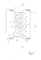
Figur 1 eine schematische perspektivische Darstellung einer Sensoranordnung einer Korrosionssonde und eines Kesselwandabschnitts mit einer Aussparung für die Sensoranordnung, -
Figur 2 die Sensoranordnung in Gebrauchslage in Draufsicht auf die dem Kesselinneren zugeordneten Elektrodenflächen der Elektroden und -
Figur 3 eine Vorrichtung aus Korrosionssonde und Kesselwandabschnitt in einer schematischen, blockschaltbildähnlichen Darstellung, wobei der Kesselwandabschnitt im Längsschnitt durch einen Verbindungssteg gemäß Schnittlinie III-III inFigur 2 veranschaulicht ist. - Die Erfindung betrifft eine Korrosionssonde 10 für einen Wandabschnitt uns beispielsgemäß einen Kesselwandabschnitt 11 und eine Vorrichtung 12 zur Bestimmung der Korrosion oder Korrosionsrate des Kesselwandabschnitts 11. Die Vorrichtung 12 umfasst dabei die Korrosionssonde 10 und den Kesselwandabschnitt 11. Alternativ zum Beschriebenen Ausführungsbeispiel kann die Korrosionssonde auch bei einem Wärmetauscher verwendet werden, so dass die Vorrichtung 12 entsprechend den Wandabschnitt eines Wärmetauschers aufweisen kann.
- Die Korrosionssonde 10 weist eine Sensoranordnung 15 mit mehreren Elektroden 16 sowie einem die Elektroden 16 tragenden Trägerteil 17 auf. Beim Ausführungsbeispiel sind drei Elektroden 16 am Trägerteil 17 befestigt. Jede Elektrode 16 weist eine dem korrosiven Medium im Kesselinneren zugewandte Elektrodenfläche 18 auf. Auf der der Elektrodenfläche 18 entgegengesetzten Rückseite 19 sind die Elektroden 16 mit einer Auswerteeinheit 20 elektrisch verbunden.
- Durch Anlegen einer Spannung an die Elektroden über die Auswerteeinheit 20 kann über die Methode der Bestimmung des linearen Polarisationswiderstandes (LPR) die Korrosion bzw. die Korrosionsrate an den Elektroden 16 über die Auswerteinheit 20 bestimmt werden. Dabei werden der Strom und die Spannung gemessen und über die Ermittlung des linearen Polarisationswiderstandes die Korrosionsrate und/oder die Korrosion bestimmt. Die Korrosion oder die Korrosionsrate an den Elektroden 16 ist ein Maß für die Korrosion bzw. Korrosionsrate am Kesselwandabschnitt 11 des Kessels. Beim Ausführungsbeispiel bestehen die Elektroden 16 aus einem artgleichen Werkstoff wie der Kesselwandabschnitt 11, so dass die Korrosion und die Korrosionsrate am Kesselwandabschnitt 11 der Korrosion bzw. der Korrosionsrate entspricht, die durch die Elektroden 16 erfasst wird.
- Optional kann zusätzlich dazu auch das elektrochemische Rauschen zwischen zwei Elektroden 16 gemessen werden, um die Neigung am Wandabschnitt zur lokalen Korrosion zu bestimmen.
- Eine Kesselwand eines Kessels, insbesondere eines Verdampfers weist typischerweise von einem zu erhitzenden bzw. zu verdampfenden Medium, insbesondere Wasser bzw. Wasserdampf durchströmte Rohre 25 auf, wobei zwei benachbarte Rohre 25 über einen Verbindungssteg 16 vorzugsweise gasdicht miteinander verbunden sind. Eine solche Kesselwand wird auch als Membranwand bezeichnet. Der betrachtete Kesselwandabschnitt 11 weist zwei in diesem Abschnitt parallel zueinander verlaufende Rohre 25 und einen dazwischen angeordneten quaderförmigen Verbindungssteg 26 auf. Die beiden Rohre 25 im betrachteten Kesselwandabschnitt 11 begrenzen einen Zwischenraum 27, in dem die Sensoranordnung 15 der Korrosionssonde 10 angeordnet ist. Die Sensoranordnung 15 befindet sich beim Ausführungsbeispiel vollständig im Zwischenraum 27. Der Zwischenraum 27 ist zum Inneren des Kessels und nach außen durch jeweils eine Ebene begrenzt, die an der Mantelfläche der beiden benachbarten Rohre 25 anliegt. Die Sensoranordnung 15 ragt aus dem Zwischenraum nicht zum Kesselinneren und vorzugsweise auch nicht zur Außenseite des Kessels hinaus.
- Wie in den Figuren zu erkennen ist, sind die Elektroden 16 in Aufnahmen des Trägerteils 17 angeordnet. Die Elektroden 16 sind beispielsgemäß als Quader ausgeführt, sie können aber auch eine andere beliebige Form haben, beispielsweise eine zylindrische Form. Zumindest die Elektrodenfläche 18 ist stufenlos und kantenlos eben ausgeführt. Beim Ausführungsbeispiel befinden sich alle Elektrodenflächen 18 in derselben Ebene. Beispielsgemäß ist auch die Rückseite 19 der Elektroden 16 mit einer ebenen Fläche ausgeführt und die Elektroden bilden sozusagen ebene Platten. Die Aufnahmen für die Elektroden 16 im Trägerteil 17 sind an die Kontur der Elektroden 16 angepasst und beispielsgemäß ebenfalls quaderförmig. Die Elektroden 16 sind beim Ausführungsbeispiel im Wesentlichen vollständig vom Trägerteil 17 aufgenommen. Die Außenflächen 18 der Elektroden haben beispielsgemäß eine rechteckförmige oder quadratische Kontur. In Abwandlung hierzu könnten auch andere Flächenformen realisiert werden. Alle Elektroden 16 sind beim Ausführungsbeispiel in ihrer Form identisch. Alle Elektroden 16 sind insbesondere aus dem gleichen Material hergestellt.
- Die Elektrodenflächen 18 befinden sich beim Ausführungsbeispiel in einer gemeinsamen Ebene mit der dem korrosiven Medium im Inneren des Kessels zugeordneten Außenfläche 28 des Trägerteils 17. Auf der dem Inneren des Kessels zugewandten Seite weist die Sensoranordnung 15 somit eine ebene Flachseite 18, 28 auf.
- Zur Anordnung im Zwischenraum 27 ist beispielsgemäß in den Verbindungssteg 26, der sich ebenfalls im Zwischenraum 27 zwischen den beiden Rohren 25 befindet, eine Aussparung 29 eingebracht, die den Verbindungssteg 26 beim Ausführungsbeispiel vollständig durchsetzt. Die Aussparung 29 im Verbindungssteg 26 ist an die Kontur des Trägerteils 17 angepasst. Vorzugsweise entspricht die Dicke D1 des Trägerteils und/oder der Elektroden 16 der Dicke D2 des Verbindungsstegs 26 (
Figur 3 ). Die Breite B1 des Trägerteils 17 ist vorzugsweise maximal so groß wie die Breite B2 des Verbindungsstegs zwischen den beiden Rohren 25 (Figur 2 ). Das Trägerteil 17 weist zwei in Erstreckungsrichtung E der Rohre 25 verlaufende Längskanten 30 auf, deren Abstand die Breite B1 des Trägerteils 17 bestimmt. Bei dem hier beschriebenen Ausführungsbeispiel ist die Breite B1 des Trägerteils 17 und mithin die Breite der Sensoranordnung 15 kleiner als die Breite B2 des Verbindungsstegs 26. Die Sensoranordnung 15 lässt sich somit problemlos in den Zwischenraum 27 zwischen den beiden Rohren 25 und beispielsgemäß in die Aussparung 29 einsetzen. Bei bisher bekanten Sensoranordnungen 15 bzw. Korrosionssonden 10 war es erforderlich, den Verlauf der Rohre 25 zu ändern, um ausreichend Platz für das Anordnen der Sensoranordnung 15 zu schaffen. Dies hat allerdings strömungstechnische und wärmetechnische Nachteile und führt zu einem erhöhten Montage- bzw. Fertigungsaufwand. Es ist gewünscht, dass die Rohre 25 möglichst parallel in Erstreckungsrichtung E durchströmt werden können. - Das Trägerteil 17 besteht aus einem elektrisch isolierenden Material. Es umschließt jede Elektrode 16 rahmenähnlich. Dadurch sind am Trägerteil 17 zwischen zwei benachbarten Aufnahmen für die Elektroden 16 Stege 31 gebildet, über die zwei unmittelbar benachbarte Elektroden 16 elektrisch voneinander getrennt sind. Die Elektroden 16 sind beim Ausführungsbeispiel in einer Reihe entlang einer Achse angeordnet, die parallel zur Erstreckungsrichtung E der beiden benachbarten Rohre 25 des Kesselwandabschnitts 11 ausgerichtet ist.
- Das Trägerteil 17 besteht vorzugsweise aus einem einzigen einheitlichen Material und ist ohne Füge- oder Trennstellen einstückig hergestellt. Die Elektroden 16 sind in den Aufnahmen am Trägerteil 17 mit Abstand zueinander angeordnet und vorzugsweise stoffschlüssig und/oder kraftschlüssig und/oder formschlüssig mit dem Trägerteil 17 verbunden. Bei einem Ausführungsbeispiel können die Elektroden am Trägerteil 17 angeschraubt. Dadurch ist eine sehr einfach handhabbare Sensoranordnung 15 aus dem Trägerteil 17 und den Elektroden 16 gebildet. Dies kann bei Herstellung des Kesselwandabschnitts 11 sehr einfach in eine Aussparung 29 im Verbindungssteg 26 eingesetzt und dort gasdicht, beispielsweise stoffschlüssig und/oder kraftschlüssig und/oder formschlüssig befestigt werden, so dass die Sensoreinheit 15 vollständig innerhalb des Zwischenraums 27 zwischen den beiden Rohren 25 angeordnet ist. Durch diese Anordnung kann auf eine separate Kühlung der Sensoreinheit 15 und insbesondere der Elektroden 16 verzichtet werden. Die erfindungsgemäße Korrosionssonde 10 ist daher frei von Kühlkanälen, Kühlleitungen oder dergleichen. Dadurch, dass das Trägerteil im Zwischenraum 27 und insbesondere in einer Aussparung 29 im Verbindungssteg 26 sitzt, ist die Wärmeabfuhr durch das durch die Rohre 25 strömende Medium ausreichend zur Kühlung der Sensoranordnung 15 mit den Elektroden 16. Separate Kühlmittel können deswegen entfallen. Somit reduzieren sich der Bauraumbedarf und der Herstellungsaufwand der Korrosionssonde 10 erheblich.
- Auf der Außenseite des Kessels bzw. des Kesselwandabschnitts 11 werden die Elektroden 16 der Sensoranordnung 15 über elektrische Leitungen mit der Auswerteeinheit 20 verbunden. Die Auswerteeinheit 20 kann daher außerhalb des Kesselinnenraums und mithin unbeaufschlagt von korrosiven Medien angeordnet werden.
- Die Erfindung betrifft eine Korrosionssonde 10 für einen Kesselwandabschnitt 11 bzw. eine Vorrichtung 12, die aus dem Kesselwandabschnitt 11 und der Korrosionssonde 10 besteht. Die Korrosionssonde 10 weist eine Sensoranordnung 15 mit einem Trägerteil 17 und wenigstens zwei Elektroden 16 auf. Die Elektroden 16 sind nebeneinander in jeweils einer Ausnehmung am Trägerteil 17 befestigt. Das Trägerteil 17 mit den Elektroden 16 wird in einem Zwischenraum 27 zwischen den beiden Rohren 25 des Kesselwandabschnitts 11 angeordnet. Dabei sitzt das Trägerteil 17 und mithin die Sensoranordnung 15 bevorzugt in einer Aussparung 29 in einem Verbindungssteg 26, der die beiden benachbarten Rohre 25 gasdicht miteinander verbindet. Die Sensoranordnung 15 aus Trägerteil 17 und Elektroden 16 ersetzt somit im Bereich der Aussparung 29 einen Abschnitt des Verbindungsstegs 26. Das Trägerteil 17 ist beispielsweise stoffschlüssig und insbesondere gasdicht in der Aussparung 29 mit dem Verbindungssteg 26 verbunden. Dadurch ergibt sich eine bauraumsparende Korrosionssonde 10, die ohne separate Kühlung und insbesondere ohne eine separate mediumdurchströmten Kühlung auskommt. Solche Korrosionssonden können an beliebig vielen Stellen der Wände eines Kessels oder eines Wärmetauschers angeordnet werden.
-
- 10
- Korrosionssonde
- 11
- Kesselwandabschnitt
- 12
- Vorrichtung
- 15
- Sensoranordnung
- 16
- Elektroden
- 17
- Trägerteil
- 18
- Elektrodenfläche
- 19
- Rückseite
- 20
- Auswerteeinheit
- 25
- Rohr
- 26
- Verbindungssteg
- 27
- Zwischenraum
- 28
- Außenfläche
- 29
- Aussparung
- 30
- Längskante
- 31
- Steg
- B1
- Breite des Trägerteils
- B2
- Breite des Verbindungsstegs
- D1
- Dicke des Trägerteils
- D2
- Dicke des Verbindungsstegs
- E
- Erstreckungsrichtung
Claims (13)
- Korrosionssonde (10) für einen Wandabschnitt (11) eines Kessels oder eines Wärmetauschers,
mit einer Sensoranordnung (15), die mehrere Elektroden (16) aufweist, die mit einem korrosiven Medium in Kontakt zu bringen sind, zur elektrochemischen Bestimmung der Korrosion und/oder der Korrosionsrate,
wobei die Elektroden (16) als Platten ausgeführt sind, die nebeneinander in einem elektrisch isolierenden Trägerteil (17) angeordnet sind, das zur Anbringung in einem Zwischenraum (27) zwischen zwei benachbarten Rohren (25) des Wandabschnitts (11) eingerichtet ist. - Korrosionssonde nach Anspruch 1,
dadurch gekennzeichnet, dass sie kühlkanalfrei ausgeführt ist. - Korrosionssonde nach Anspruch 1 oder 2,
dadurch gekennzeichnet, dass zwei der Elektroden (16) durch einen dazwischen verlaufenden Steg (31) des Trägerteils (17) voneinander getrennt sind. - Korrosionssonde nach einem der vorhergehenden Ansprüche,
dadurch gekennzeichnet, dass die Elektroden (16) jeweils eine ebene Elektrodenfläche (18) aufweisen, die in Kontakt zu bringen ist mit dem korrosiven Medium. - Korrosionssonde nach Anspruch 4,
dadurch gekennzeichnet, dass die Elektrodenflächen (18) der Elektroden (16) in einer gemeinsamen Ebene mit der dem korrosiven Medium zugeordneten Außenfläche (28) des Trägerteils (17) angeordnet sind. - Korrosionssonde nach einem der vorhergehenden Ansprüche,
dadurch gekennzeichnet, dass das Trägerteil (17) zwei insbesondere parallele Längsseiten (30) aufweist, zwischen denen die Elektroden (16) angeordnet sind. - Korrosionssonde nach einem der vorhergehenden Ansprüche,
dadurch gekennzeichnet, dass eine der Elektrodenfläche (18) entgegengesetzten Rückseite (19) jeder Elektrode (16) ein mit einer Auswerteeinheit (20) verbunden ist. - Vorrichtung (10) zur Korrosionsbestimmung,
mit einem Wandabschnitt (11) eines Kessels oder eines Wärmetauschers, der zwei von einem zu erhitzenden Medium durchströmte Rohre (25) aufweist, wobei die benachbarten Rohre (25) über einen Verbindungssteg (26) miteinander verbunden sind,
mit einer Korrosionssonde (10), die eine Sensoranordnung (15) mit mehreren Elektroden (16) aufweist, die mit einem korrosiven Medium in Kontakt zu bringen sind, zur elektrochemischen Bestimmung der Korrosion und/oder Korrosionsrate,
wobei die Elektroden (16) als Platten ausgeführt sind, die nebeneinander in einem isolierenden Trägerteil (17) angeordnet sind,
wobei das Trägerteil (17) an oder in dem Verbindungssteg (26) zwischen zwei Rohren (25) des Wandabschnitts (11) befestigt ist. - Vorrichtung nach Anspruch 8,
dadurch gekennzeichnet, dass die Breite (B1) des Trägerteils (17) maximal so groß ist wie die Breite (B2) des Verbindungsstegs (26). - Vorrichtung nach Anspruch 8 oder 9,
dadurch gekennzeichnet, dass die Elektroden (16) innerhalb der Kontur der der Innenseite des Kessels oder des Wärmetauschers zugewandten Außenfläche (28) des Trägerteils (17) angeordnet sind. - Vorrichtung nach einem der Ansprüche 8 bis 10,
dadurch gekennzeichnet, dass die Sensoranordnung (15) zwischen zwei parallel zueinander verlaufenden Rohren angeordnet ist und nicht aus dem Zwischenraum (27) zwischen den Rohren (25) an der Innenseite des Kessels oder des Wärmetauschers herausragt. - Vorrichtung nach einem der Ansprüche 8 bis 11,
dadurch gekennzeichnet, dass die Elektroden (16) aus einem artgleichen Werkstoff hergestellt sind wie der Verbindungssteg (26) und/oder die Rohre (25). - Vorrichtung nach einem der Ansprüche 8 bis 12,
dadurch gekennzeichnet, dass jede Elektrode (16) elektrisch mit einer Auswerteeinheit (20) verbunden ist, die außerhalb des Kessels oder des Wärmetauschers angeordnet ist.
Priority Applications (1)
| Application Number | Priority Date | Filing Date | Title |
|---|---|---|---|
| PL13180987T PL2700932T3 (pl) | 2012-08-23 | 2013-08-20 | Sonda korozyjna dla kotła lub wymiennika ciepła |
Applications Claiming Priority (1)
| Application Number | Priority Date | Filing Date | Title |
|---|---|---|---|
| DE102012107792.4A DE102012107792B3 (de) | 2012-08-23 | 2012-08-23 | Korrosionssonde für einen Wandabschnitt eines Kessels oder eines Wärmetauschers |
Publications (3)
| Publication Number | Publication Date |
|---|---|
| EP2700932A2 true EP2700932A2 (de) | 2014-02-26 |
| EP2700932A3 EP2700932A3 (de) | 2014-04-30 |
| EP2700932B1 EP2700932B1 (de) | 2017-08-16 |
Family
ID=49000844
Family Applications (1)
| Application Number | Title | Priority Date | Filing Date |
|---|---|---|---|
| EP13180987.3A Not-in-force EP2700932B1 (de) | 2012-08-23 | 2013-08-20 | Korrosionssonde für einen Kessel oder eines Wärmetauscher |
Country Status (3)
| Country | Link |
|---|---|
| EP (1) | EP2700932B1 (de) |
| DE (1) | DE102012107792B3 (de) |
| PL (1) | PL2700932T3 (de) |
Cited By (2)
| Publication number | Priority date | Publication date | Assignee | Title |
|---|---|---|---|---|
| DE102014007753A1 (de) | 2014-05-23 | 2015-11-26 | Steinmüller Babcock Environment Gmbh | Korrosionssonde und Verfahren zum Einbau einer Korrosionssonde |
| CN113447425A (zh) * | 2021-06-29 | 2021-09-28 | 国能(福州)热电有限公司 | 腐蚀试验装置及腐蚀检测方法 |
Families Citing this family (2)
| Publication number | Priority date | Publication date | Assignee | Title |
|---|---|---|---|---|
| US10488323B1 (en) * | 2019-03-15 | 2019-11-26 | King Saud University | Steel panel with an integrated corrosion sensor |
| SE2030171A1 (en) * | 2020-05-25 | 2021-07-20 | Ab Sandvik Materials Tech | Method, sensor and system for measuring corrosion |
Citations (1)
| Publication number | Priority date | Publication date | Assignee | Title |
|---|---|---|---|---|
| EP2325621A1 (de) | 2009-11-18 | 2011-05-25 | Technische Universität Darmstadt | Korrosionssonde |
Family Cites Families (6)
| Publication number | Priority date | Publication date | Assignee | Title |
|---|---|---|---|---|
| US3980542A (en) * | 1975-07-14 | 1976-09-14 | Petrolite Corporation | Flush mounted probe for corrosion testing |
| DE3379978D1 (en) * | 1982-01-05 | 1989-07-06 | Univ Manchester | Corrosion monitoring |
| EP0174768A3 (de) * | 1984-08-31 | 1988-11-02 | CITIES SERVICE OIL & GAS CORPORATION | Korrosionsprüfanordnung und Verfahren zur Messung der Korrosionsgeschwindigkeit |
| US6478948B2 (en) * | 2001-02-26 | 2002-11-12 | Esa Corrosion Solutions, Ltd. | Method of monitoring and controlling corrosion of furnace boiler tubes |
| CN1590981B (zh) * | 2003-08-29 | 2010-09-29 | 西安热工研究院有限公司 | 热交换器管腐蚀监测传感器的制造方法 |
| CN102128784B (zh) * | 2010-12-14 | 2012-10-10 | 华中科技大学 | 一种电偶电化学噪声腐蚀监测探针 |
-
2012
- 2012-08-23 DE DE102012107792.4A patent/DE102012107792B3/de not_active Expired - Fee Related
-
2013
- 2013-08-20 PL PL13180987T patent/PL2700932T3/pl unknown
- 2013-08-20 EP EP13180987.3A patent/EP2700932B1/de not_active Not-in-force
Patent Citations (1)
| Publication number | Priority date | Publication date | Assignee | Title |
|---|---|---|---|---|
| EP2325621A1 (de) | 2009-11-18 | 2011-05-25 | Technische Universität Darmstadt | Korrosionssonde |
Cited By (3)
| Publication number | Priority date | Publication date | Assignee | Title |
|---|---|---|---|---|
| DE102014007753A1 (de) | 2014-05-23 | 2015-11-26 | Steinmüller Babcock Environment Gmbh | Korrosionssonde und Verfahren zum Einbau einer Korrosionssonde |
| CN113447425A (zh) * | 2021-06-29 | 2021-09-28 | 国能(福州)热电有限公司 | 腐蚀试验装置及腐蚀检测方法 |
| CN113447425B (zh) * | 2021-06-29 | 2023-08-29 | 国能(福州)热电有限公司 | 腐蚀试验装置及腐蚀检测方法 |
Also Published As
| Publication number | Publication date |
|---|---|
| EP2700932A3 (de) | 2014-04-30 |
| EP2700932B1 (de) | 2017-08-16 |
| DE102012107792B3 (de) | 2014-01-16 |
| PL2700932T3 (pl) | 2018-01-31 |
Similar Documents
| Publication | Publication Date | Title |
|---|---|---|
| EP2700932B1 (de) | Korrosionssonde für einen Kessel oder eines Wärmetauscher | |
| DE10350974A1 (de) | Vorrichtung zur Feststellung von Belastungen an Faserverbund-Bauteilen | |
| WO2009156115A1 (de) | Kokille zum giessen von metall | |
| AT511358B1 (de) | Vorrichtung zum biegen von blechen | |
| EP3651930A1 (de) | Empt spule mit austauschbarem leiter | |
| WO2009109260A1 (de) | Elektrischer heizkeil | |
| EP1293759B1 (de) | Vorrichtung zum Messen der Strömungsgeschwindigkeit und/oder des Durchflusses eines Fluids | |
| DE202012104853U1 (de) | Durchflussmengenmesser zur Bestimmung der Durchflussmenge eines Fluids | |
| DE102010038684A1 (de) | Vorrichtung zur Spannungsversorgung mit einer Kühlanordnung | |
| DE102020108537B4 (de) | Verfahren zum Herstellen einer Traktionsbatterie eines Kraftfahrzeugs sowie entsprechende Herstellungseinrichtung | |
| DE102016205947B4 (de) | Reinigungsdüse mit gekrümmter Strahlführung für einen Dampf- und/oder Hochdruckreiniger | |
| DE102005019739B3 (de) | Gittersensor | |
| DE102017219418A1 (de) | Gasverteilerplatte zur Gasverteilung und Strömungsführung in Elektrolyseuren und Brennstoffzellen | |
| AT506358A1 (de) | Einfache für massenproduktion geeignete bauweise für komplexe hydropneumatische systeme | |
| EP1825232A1 (de) | Vorrichtung zum bestimmen des füllgrades eines fluides | |
| WO2011039567A1 (de) | Messvorrichtung mit verstimmbarem widerstand | |
| EP2933611A1 (de) | Coriolis-massedurchflussmessgerät | |
| DE4328337C1 (de) | Verfahren zur Bestimmung der Temperatur an einer Punktschweißverbindung sowie Anwendung des Verfahrens zur Beurteilung der Qualität der Punktschweißverbindung | |
| DE102008041771B4 (de) | Messvorrichtung mit verstimmbarem Widerstand | |
| DE102004027330B4 (de) | Mit einem Sensor zur Volumenstrommessung versehene Armatur | |
| DE202013103733U1 (de) | Schneller Stufentemperaturfühler | |
| DE202019003709U1 (de) | Anordnung zur Kalibrierung von Ultraschall-Matrix-Prüfköpfen | |
| DE102008041772A1 (de) | DFS 1 - Messvorrichtung mit Erfassung von Deformationen | |
| DE102004007767A1 (de) | Mehrfachelektrode für eine Schwingungserzeugungs- und/oder Schwingungserfassungsvorrichtung | |
| DE102022200422B3 (de) | Vorrichtung zur Ermittlung der Wärmeleitfähigkeit eines Probekörpers |
Legal Events
| Date | Code | Title | Description |
|---|---|---|---|
| PUAI | Public reference made under article 153(3) epc to a published international application that has entered the european phase |
Free format text: ORIGINAL CODE: 0009012 |
|
| AK | Designated contracting states |
Kind code of ref document: A2 Designated state(s): AL AT BE BG CH CY CZ DE DK EE ES FI FR GB GR HR HU IE IS IT LI LT LU LV MC MK MT NL NO PL PT RO RS SE SI SK SM TR |
|
| AX | Request for extension of the european patent |
Extension state: BA ME |
|
| PUAL | Search report despatched |
Free format text: ORIGINAL CODE: 0009013 |
|
| AK | Designated contracting states |
Kind code of ref document: A3 Designated state(s): AL AT BE BG CH CY CZ DE DK EE ES FI FR GB GR HR HU IE IS IT LI LT LU LV MC MK MT NL NO PL PT RO RS SE SI SK SM TR |
|
| AX | Request for extension of the european patent |
Extension state: BA ME |
|
| RIC1 | Information provided on ipc code assigned before grant |
Ipc: G01N 17/04 20060101AFI20140324BHEP |
|
| 17P | Request for examination filed |
Effective date: 20140912 |
|
| RBV | Designated contracting states (corrected) |
Designated state(s): AL AT BE BG CH CY CZ DE DK EE ES FI FR GB GR HR HU IE IS IT LI LT LU LV MC MK MT NL NO PL PT RO RS SE SI SK SM TR |
|
| 17Q | First examination report despatched |
Effective date: 20150622 |
|
| GRAP | Despatch of communication of intention to grant a patent |
Free format text: ORIGINAL CODE: EPIDOSNIGR1 |
|
| STAA | Information on the status of an ep patent application or granted ep patent |
Free format text: STATUS: GRANT OF PATENT IS INTENDED |
|
| INTG | Intention to grant announced |
Effective date: 20170322 |
|
| GRAS | Grant fee paid |
Free format text: ORIGINAL CODE: EPIDOSNIGR3 |
|
| GRAA | (expected) grant |
Free format text: ORIGINAL CODE: 0009210 |
|
| STAA | Information on the status of an ep patent application or granted ep patent |
Free format text: STATUS: THE PATENT HAS BEEN GRANTED |
|
| AK | Designated contracting states |
Kind code of ref document: B1 Designated state(s): AL AT BE BG CH CY CZ DE DK EE ES FI FR GB GR HR HU IE IS IT LI LT LU LV MC MK MT NL NO PL PT RO RS SE SI SK SM TR |
|
| REG | Reference to a national code |
Ref country code: GB Ref legal event code: FG4D Free format text: NOT ENGLISH |
|
| REG | Reference to a national code |
Ref country code: CH Ref legal event code: EP |
|
| REG | Reference to a national code |
Ref country code: IE Ref legal event code: FG4D Free format text: LANGUAGE OF EP DOCUMENT: GERMAN |
|
| REG | Reference to a national code |
Ref country code: AT Ref legal event code: REF Ref document number: 919534 Country of ref document: AT Kind code of ref document: T Effective date: 20170915 |
|
| REG | Reference to a national code |
Ref country code: DE Ref legal event code: R096 Ref document number: 502013008074 Country of ref document: DE |
|
| REG | Reference to a national code |
Ref country code: NL Ref legal event code: FP |
|
| REG | Reference to a national code |
Ref country code: LT Ref legal event code: MG4D |
|
| PG25 | Lapsed in a contracting state [announced via postgrant information from national office to epo] |
Ref country code: NO Free format text: LAPSE BECAUSE OF FAILURE TO SUBMIT A TRANSLATION OF THE DESCRIPTION OR TO PAY THE FEE WITHIN THE PRESCRIBED TIME-LIMIT Effective date: 20171116 Ref country code: SE Free format text: LAPSE BECAUSE OF FAILURE TO SUBMIT A TRANSLATION OF THE DESCRIPTION OR TO PAY THE FEE WITHIN THE PRESCRIBED TIME-LIMIT Effective date: 20170816 Ref country code: LT Free format text: LAPSE BECAUSE OF FAILURE TO SUBMIT A TRANSLATION OF THE DESCRIPTION OR TO PAY THE FEE WITHIN THE PRESCRIBED TIME-LIMIT Effective date: 20170816 |
|
| PG25 | Lapsed in a contracting state [announced via postgrant information from national office to epo] |
Ref country code: RS Free format text: LAPSE BECAUSE OF FAILURE TO SUBMIT A TRANSLATION OF THE DESCRIPTION OR TO PAY THE FEE WITHIN THE PRESCRIBED TIME-LIMIT Effective date: 20170816 Ref country code: LV Free format text: LAPSE BECAUSE OF FAILURE TO SUBMIT A TRANSLATION OF THE DESCRIPTION OR TO PAY THE FEE WITHIN THE PRESCRIBED TIME-LIMIT Effective date: 20170816 Ref country code: ES Free format text: LAPSE BECAUSE OF FAILURE TO SUBMIT A TRANSLATION OF THE DESCRIPTION OR TO PAY THE FEE WITHIN THE PRESCRIBED TIME-LIMIT Effective date: 20170816 Ref country code: GR Free format text: LAPSE BECAUSE OF FAILURE TO SUBMIT A TRANSLATION OF THE DESCRIPTION OR TO PAY THE FEE WITHIN THE PRESCRIBED TIME-LIMIT Effective date: 20171117 Ref country code: BG Free format text: LAPSE BECAUSE OF FAILURE TO SUBMIT A TRANSLATION OF THE DESCRIPTION OR TO PAY THE FEE WITHIN THE PRESCRIBED TIME-LIMIT Effective date: 20171116 Ref country code: IS Free format text: LAPSE BECAUSE OF FAILURE TO SUBMIT A TRANSLATION OF THE DESCRIPTION OR TO PAY THE FEE WITHIN THE PRESCRIBED TIME-LIMIT Effective date: 20171216 |
|
| REG | Reference to a national code |
Ref country code: CH Ref legal event code: PL |
|
| PG25 | Lapsed in a contracting state [announced via postgrant information from national office to epo] |
Ref country code: DK Free format text: LAPSE BECAUSE OF FAILURE TO SUBMIT A TRANSLATION OF THE DESCRIPTION OR TO PAY THE FEE WITHIN THE PRESCRIBED TIME-LIMIT Effective date: 20170816 Ref country code: RO Free format text: LAPSE BECAUSE OF FAILURE TO SUBMIT A TRANSLATION OF THE DESCRIPTION OR TO PAY THE FEE WITHIN THE PRESCRIBED TIME-LIMIT Effective date: 20170816 Ref country code: CH Free format text: LAPSE BECAUSE OF NON-PAYMENT OF DUE FEES Effective date: 20170831 Ref country code: LI Free format text: LAPSE BECAUSE OF NON-PAYMENT OF DUE FEES Effective date: 20170831 |
|
| REG | Reference to a national code |
Ref country code: DE Ref legal event code: R097 Ref document number: 502013008074 Country of ref document: DE |
|
| REG | Reference to a national code |
Ref country code: IE Ref legal event code: MM4A |
|
| PG25 | Lapsed in a contracting state [announced via postgrant information from national office to epo] |
Ref country code: SK Free format text: LAPSE BECAUSE OF FAILURE TO SUBMIT A TRANSLATION OF THE DESCRIPTION OR TO PAY THE FEE WITHIN THE PRESCRIBED TIME-LIMIT Effective date: 20170816 Ref country code: MC Free format text: LAPSE BECAUSE OF FAILURE TO SUBMIT A TRANSLATION OF THE DESCRIPTION OR TO PAY THE FEE WITHIN THE PRESCRIBED TIME-LIMIT Effective date: 20170816 Ref country code: IT Free format text: LAPSE BECAUSE OF FAILURE TO SUBMIT A TRANSLATION OF THE DESCRIPTION OR TO PAY THE FEE WITHIN THE PRESCRIBED TIME-LIMIT Effective date: 20170816 Ref country code: SM Free format text: LAPSE BECAUSE OF FAILURE TO SUBMIT A TRANSLATION OF THE DESCRIPTION OR TO PAY THE FEE WITHIN THE PRESCRIBED TIME-LIMIT Effective date: 20170816 Ref country code: EE Free format text: LAPSE BECAUSE OF FAILURE TO SUBMIT A TRANSLATION OF THE DESCRIPTION OR TO PAY THE FEE WITHIN THE PRESCRIBED TIME-LIMIT Effective date: 20170816 |
|
| REG | Reference to a national code |
Ref country code: BE Ref legal event code: MM Effective date: 20170831 |
|
| PLBE | No opposition filed within time limit |
Free format text: ORIGINAL CODE: 0009261 |
|
| STAA | Information on the status of an ep patent application or granted ep patent |
Free format text: STATUS: NO OPPOSITION FILED WITHIN TIME LIMIT |
|
| PG25 | Lapsed in a contracting state [announced via postgrant information from national office to epo] |
Ref country code: LU Free format text: LAPSE BECAUSE OF NON-PAYMENT OF DUE FEES Effective date: 20170820 |
|
| REG | Reference to a national code |
Ref country code: FR Ref legal event code: ST Effective date: 20180607 |
|
| 26N | No opposition filed |
Effective date: 20180517 |
|
| PG25 | Lapsed in a contracting state [announced via postgrant information from national office to epo] |
Ref country code: IE Free format text: LAPSE BECAUSE OF NON-PAYMENT OF DUE FEES Effective date: 20170820 |
|
| PG25 | Lapsed in a contracting state [announced via postgrant information from national office to epo] |
Ref country code: FR Free format text: LAPSE BECAUSE OF NON-PAYMENT OF DUE FEES Effective date: 20171016 Ref country code: SI Free format text: LAPSE BECAUSE OF FAILURE TO SUBMIT A TRANSLATION OF THE DESCRIPTION OR TO PAY THE FEE WITHIN THE PRESCRIBED TIME-LIMIT Effective date: 20170816 Ref country code: BE Free format text: LAPSE BECAUSE OF NON-PAYMENT OF DUE FEES Effective date: 20170831 |
|
| PG25 | Lapsed in a contracting state [announced via postgrant information from national office to epo] |
Ref country code: MT Free format text: LAPSE BECAUSE OF FAILURE TO SUBMIT A TRANSLATION OF THE DESCRIPTION OR TO PAY THE FEE WITHIN THE PRESCRIBED TIME-LIMIT Effective date: 20170816 |
|
| PG25 | Lapsed in a contracting state [announced via postgrant information from national office to epo] |
Ref country code: HU Free format text: LAPSE BECAUSE OF FAILURE TO SUBMIT A TRANSLATION OF THE DESCRIPTION OR TO PAY THE FEE WITHIN THE PRESCRIBED TIME-LIMIT; INVALID AB INITIO Effective date: 20130820 |
|
| PG25 | Lapsed in a contracting state [announced via postgrant information from national office to epo] |
Ref country code: CY Free format text: LAPSE BECAUSE OF NON-PAYMENT OF DUE FEES Effective date: 20170816 |
|
| PGFP | Annual fee paid to national office [announced via postgrant information from national office to epo] |
Ref country code: CZ Payment date: 20190820 Year of fee payment: 7 Ref country code: TR Payment date: 20190820 Year of fee payment: 7 |
|
| PG25 | Lapsed in a contracting state [announced via postgrant information from national office to epo] |
Ref country code: MK Free format text: LAPSE BECAUSE OF FAILURE TO SUBMIT A TRANSLATION OF THE DESCRIPTION OR TO PAY THE FEE WITHIN THE PRESCRIBED TIME-LIMIT Effective date: 20170816 |
|
| PGFP | Annual fee paid to national office [announced via postgrant information from national office to epo] |
Ref country code: PL Payment date: 20190820 Year of fee payment: 7 |
|
| PGFP | Annual fee paid to national office [announced via postgrant information from national office to epo] |
Ref country code: AT Payment date: 20190822 Year of fee payment: 7 |
|
| PG25 | Lapsed in a contracting state [announced via postgrant information from national office to epo] |
Ref country code: PT Free format text: LAPSE BECAUSE OF FAILURE TO SUBMIT A TRANSLATION OF THE DESCRIPTION OR TO PAY THE FEE WITHIN THE PRESCRIBED TIME-LIMIT Effective date: 20170816 |
|
| PG25 | Lapsed in a contracting state [announced via postgrant information from national office to epo] |
Ref country code: HR Free format text: LAPSE BECAUSE OF FAILURE TO SUBMIT A TRANSLATION OF THE DESCRIPTION OR TO PAY THE FEE WITHIN THE PRESCRIBED TIME-LIMIT Effective date: 20170816 |
|
| PG25 | Lapsed in a contracting state [announced via postgrant information from national office to epo] |
Ref country code: AL Free format text: LAPSE BECAUSE OF FAILURE TO SUBMIT A TRANSLATION OF THE DESCRIPTION OR TO PAY THE FEE WITHIN THE PRESCRIBED TIME-LIMIT Effective date: 20170816 |
|
| REG | Reference to a national code |
Ref country code: AT Ref legal event code: MM01 Ref document number: 919534 Country of ref document: AT Kind code of ref document: T Effective date: 20200820 |
|
| PG25 | Lapsed in a contracting state [announced via postgrant information from national office to epo] |
Ref country code: CZ Free format text: LAPSE BECAUSE OF NON-PAYMENT OF DUE FEES Effective date: 20200820 |
|
| PG25 | Lapsed in a contracting state [announced via postgrant information from national office to epo] |
Ref country code: AT Free format text: LAPSE BECAUSE OF NON-PAYMENT OF DUE FEES Effective date: 20200820 |
|
| PGFP | Annual fee paid to national office [announced via postgrant information from national office to epo] |
Ref country code: NL Payment date: 20210830 Year of fee payment: 9 |
|
| PGFP | Annual fee paid to national office [announced via postgrant information from national office to epo] |
Ref country code: FI Payment date: 20210826 Year of fee payment: 9 |
|
| PGFP | Annual fee paid to national office [announced via postgrant information from national office to epo] |
Ref country code: GB Payment date: 20210830 Year of fee payment: 9 |
|
| PG25 | Lapsed in a contracting state [announced via postgrant information from national office to epo] |
Ref country code: TR Free format text: LAPSE BECAUSE OF NON-PAYMENT OF DUE FEES Effective date: 20200820 |
|
| PGFP | Annual fee paid to national office [announced via postgrant information from national office to epo] |
Ref country code: DE Payment date: 20220928 Year of fee payment: 10 |
|
| PG25 | Lapsed in a contracting state [announced via postgrant information from national office to epo] |
Ref country code: PL Free format text: LAPSE BECAUSE OF NON-PAYMENT OF DUE FEES Effective date: 20200820 |
|
| REG | Reference to a national code |
Ref country code: NL Ref legal event code: MM Effective date: 20220901 |
|
| GBPC | Gb: european patent ceased through non-payment of renewal fee |
Effective date: 20220820 |
|
| PG25 | Lapsed in a contracting state [announced via postgrant information from national office to epo] |
Ref country code: FI Free format text: LAPSE BECAUSE OF NON-PAYMENT OF DUE FEES Effective date: 20220820 |
|
| PG25 | Lapsed in a contracting state [announced via postgrant information from national office to epo] |
Ref country code: NL Free format text: LAPSE BECAUSE OF NON-PAYMENT OF DUE FEES Effective date: 20220901 |
|
| PG25 | Lapsed in a contracting state [announced via postgrant information from national office to epo] |
Ref country code: GB Free format text: LAPSE BECAUSE OF NON-PAYMENT OF DUE FEES Effective date: 20220820 |
|
| REG | Reference to a national code |
Ref country code: DE Ref legal event code: R119 Ref document number: 502013008074 Country of ref document: DE |
|
| PG25 | Lapsed in a contracting state [announced via postgrant information from national office to epo] |
Ref country code: DE Free format text: LAPSE BECAUSE OF NON-PAYMENT OF DUE FEES Effective date: 20240301 |