EP2700932A2 - Sonde de corrosion pour un segment de mur d'une chaudière ou d'un échangeur de chaleur - Google Patents
Sonde de corrosion pour un segment de mur d'une chaudière ou d'un échangeur de chaleur Download PDFInfo
- Publication number
- EP2700932A2 EP2700932A2 EP13180987.3A EP13180987A EP2700932A2 EP 2700932 A2 EP2700932 A2 EP 2700932A2 EP 13180987 A EP13180987 A EP 13180987A EP 2700932 A2 EP2700932 A2 EP 2700932A2
- Authority
- EP
- European Patent Office
- Prior art keywords
- electrodes
- corrosion
- boiler
- tubes
- wall section
- Prior art date
- Legal status (The legal status is an assumption and is not a legal conclusion. Google has not performed a legal analysis and makes no representation as to the accuracy of the status listed.)
- Granted
Links
- 230000007797 corrosion Effects 0.000 title claims abstract description 76
- 238000005260 corrosion Methods 0.000 title claims abstract description 76
- 239000000523 sample Substances 0.000 title claims abstract description 45
- 238000001816 cooling Methods 0.000 claims description 16
- 238000011156 evaluation Methods 0.000 claims description 12
- 239000000463 material Substances 0.000 claims description 7
- 230000010287 polarization Effects 0.000 description 4
- 238000004519 manufacturing process Methods 0.000 description 3
- 238000005259 measurement Methods 0.000 description 2
- 238000000034 method Methods 0.000 description 2
- 229910000851 Alloy steel Inorganic materials 0.000 description 1
- VYZAMTAEIAYCRO-UHFFFAOYSA-N Chromium Chemical compound [Cr] VYZAMTAEIAYCRO-UHFFFAOYSA-N 0.000 description 1
- 229910010293 ceramic material Inorganic materials 0.000 description 1
- 229910052804 chromium Inorganic materials 0.000 description 1
- 239000011651 chromium Substances 0.000 description 1
- 230000001419 dependent effect Effects 0.000 description 1
- 239000012777 electrically insulating material Substances 0.000 description 1
- 230000017525 heat dissipation Effects 0.000 description 1
- 239000012528 membrane Substances 0.000 description 1
- 238000012986 modification Methods 0.000 description 1
- 230000004048 modification Effects 0.000 description 1
- 229910052574 oxide ceramic Inorganic materials 0.000 description 1
- 239000011224 oxide ceramic Substances 0.000 description 1
- TWNQGVIAIRXVLR-UHFFFAOYSA-N oxo(oxoalumanyloxy)alumane Chemical compound O=[Al]O[Al]=O TWNQGVIAIRXVLR-UHFFFAOYSA-N 0.000 description 1
- 238000000926 separation method Methods 0.000 description 1
- 230000035939 shock Effects 0.000 description 1
- 239000013589 supplement Substances 0.000 description 1
- XLYOFNOQVPJJNP-UHFFFAOYSA-N water Substances O XLYOFNOQVPJJNP-UHFFFAOYSA-N 0.000 description 1
Images


Classifications
-
- G—PHYSICS
- G01—MEASURING; TESTING
- G01N—INVESTIGATING OR ANALYSING MATERIALS BY DETERMINING THEIR CHEMICAL OR PHYSICAL PROPERTIES
- G01N17/00—Investigating resistance of materials to the weather, to corrosion, or to light
- G01N17/04—Corrosion probes
Definitions
- the invention relates to a corrosion probe, in particular for a wall section of a boiler or a heat exchanger, for example for the wall section of a boiler for steam generation.
- the invention also relates to a device for measuring the corrosion or corrosion rate, which comprises a wall section and a corrosion probe attached to the wall section.
- the corrosion probe serves to determine the corrosion or the corrosion rate of the wall section or the wall of the boiler or of the heat exchanger. It has more than one and, for example, two or three electrodes for this purpose.
- the electrodes are connected to an evaluation unit.
- the method of measuring the linear polarization resistance (LPR), the corrosion rate and / or corrosion can be determined.
- a corrosion probe is off EP 2 325 621 A1 known.
- the corrosion probe consists of three juxtaposed electrodes, which together form a circular plate.
- the corrosion probe is located at the tip of a lance and can be introduced into a boiler with the aid of a lance for corrosion determination. Cooling channels run inside the lance to cool the electrodes that are exposed to the heat inside the boiler.
- Such corrosion probes are expensive.
- the electrodes must be permanently connected via cooling channels running in the lance be connected to an external cooling system to ensure adequate cooling.
- the cooling channels also require a lot of space, which in turn makes it difficult to arrange the lance in an opening in the boiler wall section into the interior of the boiler.
- the corrosion probe has a sensor arrangement with several and at least two or three electrodes. During the measurement, the electrodes come into contact with the corrosive medium inside the vessel.
- the electrodes are preferably designed as flat plates and arranged side by side in an electrically insulating carrier part.
- the support member is adapted and arranged to be disposed in a space between two adjacent tubes of the boiler wall portion.
- the width of the carrier part is for this purpose in particular smaller than the distance between two adjacent tubes of the associated boiler wall section.
- the electrodes may be arranged side by side in the extension direction of the tubes. In particular, in a connecting web between two adjacent tubes of the boiler wall portion, there is a recess in which the carrier part is arranged and fastened.
- the carrier part is arranged in its use position between two tubes of the boiler wall section on or in the connecting web, the cooling of the electrodes via the flowing medium through the tubes.
- the corrosion probe can be designed completely free of cooling channels. Separate cooling of the corrosion probe is therefore not required.
- the carrier part consists of a ceramic material, in particular of an aluminum oxide ceramic. This material not only has a good electrically insulating property, but also has high heat resistance and thermal shock resistance.
- the corrosion probe according to the invention requires only a very small space, which is essentially determined by the size of the corrosive medium facing electrode surfaces of the electrodes.
- the electrodes may, for example, be arranged next to one another in a row, so that they can be inserted into the intermediate space very simply parallel to the extension direction of the tubes, without the need for expensive structural measures on the boiler wall section.
- the carrier part can be very easily inserted, for example, by a cohesive and / or non-positive and / or positive connection in the recess on the connecting web and in particular gas-tight connect to the connecting web.
- the sensor device of the corrosion probe formed from the carrier part with the electrodes can in one embodiment replace the connecting web of the vessel wall section in the region of the recess.
- the recess can also be designed as a recess be that does not completely break the connecting web, so that the gas tightness is not affected by the recess.
- two adjacent electrodes are electrically insulated from one another by a respective web of the carrier part extending therebetween.
- the carrier part for each electrode may have a separate receiving area. Additional insulating components between the electrodes can be omitted.
- the electrode surface of the electrodes assigned to the corrosive medium is preferably designed to be planar and edgeless.
- the electrode surfaces of the electrodes of the sensor assembly of the corrosion probe can lie in a plane in a preferred embodiment. This plane may coincide with the plane in which the outer surface of the support member facing the corrosive medium is located.
- a very flat-fitting corrosion probe can be achieved, which does not or only slightly protrudes from a connecting web between two adjacent pipes in the direction of the boiler interior of the boiler wall portion. At least the corrosion probe in its position of use does not protrude from the space between two adjacent pipes in the direction of the interior of the boiler.
- the carrier part has two longitudinal sides extending parallel to one another. These longitudinal sides extend in the position of use of the corrosion probe preferably parallel to the extension direction of the tubes of the boiler wall section.
- the two transverse sides, which connect the long sides, can run straight or curved.
- the electrodes or the electrode surfaces are preferably arranged completely within the contour of the outer surface of the carrier part.
- each electrode opposite the electrode surface is connected to an evaluation unit.
- the evaluation unit for example, a voltage is applied between two electrodes and the corrosion and / or the corrosion rate of the boiler wall section can be determined on the basis of a current measurement, in particular via the determination of the linear polarization resistance.
- the evaluation unit is arranged in particular outside the boiler in the region of the boiler outside of the boiler wall section.
- the width of the carrier part is at most as large as the width of the connecting web to which the carrier part is fastened.
- the width of the connecting web is constant at least at the considered boiler wall section, so that the tubes can run parallel to one another.
- the electrodes consist of a material equal to the connecting web and / or the tubes of the boiler wall section, in particular a chromium-containing steel alloy.
- all electrodes are made of the same material.
- the invention relates to a corrosion probe 10 for a wall section us beispielsdorf a boiler wall portion 11 and a device 12 for determining the corrosion or corrosion rate of the boiler wall portion 11.
- the device 12 includes the corrosion probe 10 and the boiler wall portion 11.
- the corrosion probe also in a heat exchanger can be used, so that the device 12 may correspondingly have the wall portion of a heat exchanger.
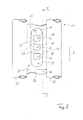
- the corrosion probe 10 has a sensor arrangement 15 with a plurality of electrodes 16 and a support member 17 carrying the electrodes 16.
- three electrodes 16 are attached to the support member 17.
- Each electrode 16 has an electrode surface 18 facing the corrosive medium in the interior of the vessel.
- the electrodes 16 are electrically connected to an evaluation unit 20.
- the corrosion or the corrosion rate at the electrodes 16 via the evaluation unit 20 can be determined via the method of determining the linear polarization resistance (LPR).
- the current and the voltage are measured and determined by determining the linear polarization resistance, the corrosion rate and / or corrosion.
- the corrosion or corrosion rate at the electrodes 16 is a measure of the corrosion or corrosion rate on the boiler wall section 11 of the boiler.
- the electrodes 16 consist of a similar material as the boiler wall section 11, so that the corrosion and the corrosion rate at the boiler wall section 11 corresponds to the corrosion or the corrosion rate which is detected by the electrodes 16.
- the electrochemical noise between two electrodes 16 may be measured to determine the slope at the wall portion for local corrosion.
- a boiler wall of a boiler typically has pipes 25 through which a medium 25 flows, in particular water or steam, through which two adjacent pipes 25 are preferably connected in a gas-tight manner via a connecting web 16.
- a boiler wall is also referred to as a membrane wall.
- the considered boiler wall section 11 has two tubes 25 running parallel to one another in this section and a cuboid connecting web 26 arranged therebetween.
- the two tubes 25 in the considered boiler wall portion 11 define a gap 27 in which the sensor assembly 15 of the corrosion probe 10 is arranged.
- the sensor assembly 15 is located in the embodiment completely in the intermediate space 27.
- the intermediate space 27 is limited to the interior of the boiler and to the outside by a respective plane which rests against the lateral surface of the two adjacent tubes 25.
- the sensor assembly 15 does not protrude from the gap to the interior of the boiler and preferably not to the outside of the boiler out.
- the electrodes 16 are arranged in receptacles of the carrier part 17.
- the electrodes 16 are designed as cuboid, for example, but they can also have any other shape, such as a cylindrical shape.
- At least the electrode surface 18 is designed to be stepless and edgeless. In the embodiment, all electrode surfaces 18 are in the same plane.
- Example is also the Rear side 19 of the electrodes 16 are designed with a flat surface and the electrodes form, so to speak, flat plates.
- the receptacles for the electrodes 16 in the support member 17 are adapted to the contour of the electrodes 16 and, for example, also cuboid.
- the electrodes 16 are substantially completely received by the support member 17 in the embodiment.
- the outer surfaces 18 of the electrodes have, for example, a rectangular or square contour. In a modification to this, other surface shapes could be realized. All electrodes 16 are identical in shape in the embodiment. All electrodes 16 are in particular made of the same material.
- the electrode surfaces 18 are in the embodiment in a common plane with the corrosive medium inside the boiler associated outer surface 28 of the support member 17. On the interior of the boiler side facing the sensor assembly 15 thus has a flat flat side 18, 28.
- a recess 29 is introduced, for example, in the connecting web 26, which is also located in the intermediate space 27 between the two tubes 25, which completely penetrates the connecting web 26 in the embodiment.
- the recess 29 in the connecting web 26 is adapted to the contour of the support part 17.
- the thickness D1 of the carrier part and / or of the electrodes 16 corresponds to the thickness D2 of the connecting web 26 (FIG. FIG. 3 ).
- the width B1 of the carrier part 17 is preferably at most as large as the width B2 of the connecting web between the two tubes 25 (FIG. FIG. 2 ).
- the support part 17 has two extending in the direction of extension E of the tubes 25 longitudinal edges 30, whose distance determines the width B1 of the support member 17.
- the width B1 of the carrier part 17 and thus the width of the sensor assembly 15 is smaller than the width B2 of the connecting web 26.
- the sensor assembly 15 can thus be easily inserted into the gap 27 between the two tubes 25 and example in the recess 29.
- this has fluidic and thermotechnical disadvantages and leads to an increased assembly or manufacturing costs. It is desired that the tubes 25 can be traversed as parallel as possible in the extension direction E.
- the support member 17 is made of an electrically insulating material. It encloses each electrode 16 frame-like. As a result, webs 31 are formed on the carrier part 17 between two adjacent receptacles for the electrodes 16, via which two directly adjacent electrodes 16 are electrically separated from one another.
- the electrodes 16 are arranged in the embodiment in a row along an axis which is aligned parallel to the extension direction E of the two adjacent tubes 25 of the boiler wall portion 11.
- the support member 17 is preferably made of a single uniform material and is made in one piece without joining or separation points.
- the electrodes 16 are arranged in the receptacles on the support member 17 at a distance from each other and preferably cohesively and / or non-positively and / or positively connected to the support member 17. In one embodiment, the electrodes may be screwed to the support member 17. As a result, a sensor arrangement 15 that is very easy to handle is formed from the carrier part 17 and the electrodes 16.
- the boiler wall section 11 are very easily inserted into a recess 29 in the connecting web 26 and there gas-tight, for example, materially and / or non-positively and / or positively secured, so that the sensor unit 15 is disposed completely within the gap 27 between the two tubes 25.
- This arrangement makes it possible to dispense with separate cooling of the sensor unit 15 and in particular of the electrodes 16.
- the corrosion probe 10 according to the invention is therefore free of cooling channels, cooling lines or the like. Because the carrier part is seated in the intermediate space 27 and in particular in a recess 29 in the connecting web 26, the heat dissipation through the medium flowing through the tubes 25 is sufficient for cooling the sensor arrangement 15 with the electrodes 16. Separate cooling means can therefore be dispensed with. Thus, the space requirement and the production cost of the corrosion probe 10 reduce considerably.
- the electrodes 16 of the sensor arrangement 15 are connected to the evaluation unit 20 via electrical lines.
- the evaluation unit 20 can therefore be arranged outside the boiler interior and thus unencumbered by corrosive media.
- the invention relates to a corrosion probe 10 for a boiler wall section 11 or a device 12 which consists of the boiler wall section 11 and the corrosion probe 10.
- the corrosion probe 10 has a sensor arrangement 15 with a carrier part 17 and at least two electrodes 16.
- the electrodes 16 are fastened next to one another in each case in a recess on the carrier part 17.
- the support part 17 with the electrodes 16 is arranged in a gap 27 between the two tubes 25 of the boiler wall portion 11.
- the support member 17 and thus the sensor assembly sits 15 preferably in a recess 29 in a connecting web 26 which connects the two adjacent tubes 25 gas-tight with each other.
- the sensor arrangement 15 of carrier part 17 and electrodes 16 thus replaces a section of the connecting web 26 in the region of the recess 29.
- the carrier part 17 is connected to the connecting web 26 in a material-locking and, in particular, gas-tight manner in the recess 29.
- Such corrosion probes can be arranged at any number of locations on the walls of a boiler or a heat exchanger.
Landscapes
- Life Sciences & Earth Sciences (AREA)
- Biodiversity & Conservation Biology (AREA)
- Ecology (AREA)
- Environmental & Geological Engineering (AREA)
- Environmental Sciences (AREA)
- Physics & Mathematics (AREA)
- Health & Medical Sciences (AREA)
- Chemical & Material Sciences (AREA)
- Analytical Chemistry (AREA)
- Biochemistry (AREA)
- General Health & Medical Sciences (AREA)
- General Physics & Mathematics (AREA)
- Immunology (AREA)
- Pathology (AREA)
- Testing Resistance To Weather, Investigating Materials By Mechanical Methods (AREA)
Priority Applications (1)
| Application Number | Priority Date | Filing Date | Title |
|---|---|---|---|
| PL13180987T PL2700932T3 (pl) | 2012-08-23 | 2013-08-20 | Sonda korozyjna dla kotła lub wymiennika ciepła |
Applications Claiming Priority (1)
| Application Number | Priority Date | Filing Date | Title |
|---|---|---|---|
| DE102012107792.4A DE102012107792B3 (de) | 2012-08-23 | 2012-08-23 | Korrosionssonde für einen Wandabschnitt eines Kessels oder eines Wärmetauschers |
Publications (3)
| Publication Number | Publication Date |
|---|---|
| EP2700932A2 true EP2700932A2 (fr) | 2014-02-26 |
| EP2700932A3 EP2700932A3 (fr) | 2014-04-30 |
| EP2700932B1 EP2700932B1 (fr) | 2017-08-16 |
Family
ID=49000844
Family Applications (1)
| Application Number | Title | Priority Date | Filing Date |
|---|---|---|---|
| EP13180987.3A Not-in-force EP2700932B1 (fr) | 2012-08-23 | 2013-08-20 | Sonde de corrosion pour une chaudière ou un échangeur de chaleur |
Country Status (3)
| Country | Link |
|---|---|
| EP (1) | EP2700932B1 (fr) |
| DE (1) | DE102012107792B3 (fr) |
| PL (1) | PL2700932T3 (fr) |
Cited By (2)
| Publication number | Priority date | Publication date | Assignee | Title |
|---|---|---|---|---|
| DE102014007753A1 (de) | 2014-05-23 | 2015-11-26 | Steinmüller Babcock Environment Gmbh | Korrosionssonde und Verfahren zum Einbau einer Korrosionssonde |
| CN113447425A (zh) * | 2021-06-29 | 2021-09-28 | 国能(福州)热电有限公司 | 腐蚀试验装置及腐蚀检测方法 |
Families Citing this family (2)
| Publication number | Priority date | Publication date | Assignee | Title |
|---|---|---|---|---|
| US10488323B1 (en) * | 2019-03-15 | 2019-11-26 | King Saud University | Steel panel with an integrated corrosion sensor |
| SE2030171A1 (en) * | 2020-05-25 | 2021-07-20 | Ab Sandvik Materials Tech | Method, sensor and system for measuring corrosion |
Citations (1)
| Publication number | Priority date | Publication date | Assignee | Title |
|---|---|---|---|---|
| EP2325621A1 (fr) | 2009-11-18 | 2011-05-25 | Technische Universität Darmstadt | Sonde de corrosion |
Family Cites Families (6)
| Publication number | Priority date | Publication date | Assignee | Title |
|---|---|---|---|---|
| US3980542A (en) * | 1975-07-14 | 1976-09-14 | Petrolite Corporation | Flush mounted probe for corrosion testing |
| EP0084404B1 (fr) * | 1982-01-05 | 1989-05-31 | University Of Manchester Institute Of Science And Technology | Surveillance de la corrosion |
| EP0174768A3 (fr) * | 1984-08-31 | 1988-11-02 | CITIES SERVICE OIL & GAS CORPORATION | Capteur de corrosion et méthode de mesure de vitesses de corrosion |
| US6478948B2 (en) * | 2001-02-26 | 2002-11-12 | Esa Corrosion Solutions, Ltd. | Method of monitoring and controlling corrosion of furnace boiler tubes |
| CN1590981B (zh) * | 2003-08-29 | 2010-09-29 | 西安热工研究院有限公司 | 热交换器管腐蚀监测传感器的制造方法 |
| CN102128784B (zh) * | 2010-12-14 | 2012-10-10 | 华中科技大学 | 一种电偶电化学噪声腐蚀监测探针 |
-
2012
- 2012-08-23 DE DE102012107792.4A patent/DE102012107792B3/de not_active Expired - Fee Related
-
2013
- 2013-08-20 EP EP13180987.3A patent/EP2700932B1/fr not_active Not-in-force
- 2013-08-20 PL PL13180987T patent/PL2700932T3/pl unknown
Patent Citations (1)
| Publication number | Priority date | Publication date | Assignee | Title |
|---|---|---|---|---|
| EP2325621A1 (fr) | 2009-11-18 | 2011-05-25 | Technische Universität Darmstadt | Sonde de corrosion |
Cited By (3)
| Publication number | Priority date | Publication date | Assignee | Title |
|---|---|---|---|---|
| DE102014007753A1 (de) | 2014-05-23 | 2015-11-26 | Steinmüller Babcock Environment Gmbh | Korrosionssonde und Verfahren zum Einbau einer Korrosionssonde |
| CN113447425A (zh) * | 2021-06-29 | 2021-09-28 | 国能(福州)热电有限公司 | 腐蚀试验装置及腐蚀检测方法 |
| CN113447425B (zh) * | 2021-06-29 | 2023-08-29 | 国能(福州)热电有限公司 | 腐蚀试验装置及腐蚀检测方法 |
Also Published As
| Publication number | Publication date |
|---|---|
| PL2700932T3 (pl) | 2018-01-31 |
| DE102012107792B3 (de) | 2014-01-16 |
| EP2700932B1 (fr) | 2017-08-16 |
| EP2700932A3 (fr) | 2014-04-30 |
Similar Documents
| Publication | Publication Date | Title |
|---|---|---|
| EP2700932B1 (fr) | Sonde de corrosion pour une chaudière ou un échangeur de chaleur | |
| EP1920264B1 (fr) | Capteur de batterie | |
| DE10350974A1 (de) | Vorrichtung zur Feststellung von Belastungen an Faserverbund-Bauteilen | |
| WO2009156115A1 (fr) | Lingotière pour la coulée de métal | |
| EP2771135B1 (fr) | Dispositif de pliage de tôles | |
| EP3651930A1 (fr) | Bobine tiem à conducteur interchangeable | |
| EP2247433A1 (fr) | Clavette électrique chauffante | |
| EP1293759B1 (fr) | Dispositif de mesure de la vitesse et/ou du débit d'un fluide | |
| DE202012104853U1 (de) | Durchflussmengenmesser zur Bestimmung der Durchflussmenge eines Fluids | |
| DE10227454A1 (de) | Verfahren zur Temperaturmessung sowie Anlegetemperaturfühler | |
| DE102012208893B4 (de) | Verfahren zum Betreiben einer Messeinrichtung einer pneumatischen Auflagenkontrollvorrichtung | |
| DE3600656C2 (fr) | ||
| DE102005019739B3 (de) | Gittersensor | |
| DE102020108537A1 (de) | Verfahren zum Herstellen einer Traktionsbatterie eines Kraftfahrzeugs sowie entsprechende Herstellungseinrichtung | |
| AT506358A1 (de) | Einfache für massenproduktion geeignete bauweise für komplexe hydropneumatische systeme | |
| EP1825232A1 (fr) | Dispositif de determination du niveau de remplissage d'un fluide | |
| WO2011039567A1 (fr) | Dispositif de mesure à résistance désaccordable | |
| EP2933611A1 (fr) | Débitmètre massique coriolis | |
| DE4328337C1 (de) | Verfahren zur Bestimmung der Temperatur an einer Punktschweißverbindung sowie Anwendung des Verfahrens zur Beurteilung der Qualität der Punktschweißverbindung | |
| DE102008041771A1 (de) | Messvorrichtung mit verstimmbarem Widerstand | |
| DE102017219418A1 (de) | Gasverteilerplatte zur Gasverteilung und Strömungsführung in Elektrolyseuren und Brennstoffzellen | |
| DE102016212728A1 (de) | Prüfaufbau für Biegeversuche an CFK Bauteilen | |
| DE202013103733U1 (de) | Schneller Stufentemperaturfühler | |
| DE102008041772A1 (de) | DFS 1 - Messvorrichtung mit Erfassung von Deformationen | |
| DE102004007767A1 (de) | Mehrfachelektrode für eine Schwingungserzeugungs- und/oder Schwingungserfassungsvorrichtung |
Legal Events
| Date | Code | Title | Description |
|---|---|---|---|
| PUAI | Public reference made under article 153(3) epc to a published international application that has entered the european phase |
Free format text: ORIGINAL CODE: 0009012 |
|
| AK | Designated contracting states |
Kind code of ref document: A2 Designated state(s): AL AT BE BG CH CY CZ DE DK EE ES FI FR GB GR HR HU IE IS IT LI LT LU LV MC MK MT NL NO PL PT RO RS SE SI SK SM TR |
|
| AX | Request for extension of the european patent |
Extension state: BA ME |
|
| PUAL | Search report despatched |
Free format text: ORIGINAL CODE: 0009013 |
|
| AK | Designated contracting states |
Kind code of ref document: A3 Designated state(s): AL AT BE BG CH CY CZ DE DK EE ES FI FR GB GR HR HU IE IS IT LI LT LU LV MC MK MT NL NO PL PT RO RS SE SI SK SM TR |
|
| AX | Request for extension of the european patent |
Extension state: BA ME |
|
| RIC1 | Information provided on ipc code assigned before grant |
Ipc: G01N 17/04 20060101AFI20140324BHEP |
|
| 17P | Request for examination filed |
Effective date: 20140912 |
|
| RBV | Designated contracting states (corrected) |
Designated state(s): AL AT BE BG CH CY CZ DE DK EE ES FI FR GB GR HR HU IE IS IT LI LT LU LV MC MK MT NL NO PL PT RO RS SE SI SK SM TR |
|
| 17Q | First examination report despatched |
Effective date: 20150622 |
|
| GRAP | Despatch of communication of intention to grant a patent |
Free format text: ORIGINAL CODE: EPIDOSNIGR1 |
|
| STAA | Information on the status of an ep patent application or granted ep patent |
Free format text: STATUS: GRANT OF PATENT IS INTENDED |
|
| INTG | Intention to grant announced |
Effective date: 20170322 |
|
| GRAS | Grant fee paid |
Free format text: ORIGINAL CODE: EPIDOSNIGR3 |
|
| GRAA | (expected) grant |
Free format text: ORIGINAL CODE: 0009210 |
|
| STAA | Information on the status of an ep patent application or granted ep patent |
Free format text: STATUS: THE PATENT HAS BEEN GRANTED |
|
| AK | Designated contracting states |
Kind code of ref document: B1 Designated state(s): AL AT BE BG CH CY CZ DE DK EE ES FI FR GB GR HR HU IE IS IT LI LT LU LV MC MK MT NL NO PL PT RO RS SE SI SK SM TR |
|
| REG | Reference to a national code |
Ref country code: GB Ref legal event code: FG4D Free format text: NOT ENGLISH |
|
| REG | Reference to a national code |
Ref country code: CH Ref legal event code: EP |
|
| REG | Reference to a national code |
Ref country code: IE Ref legal event code: FG4D Free format text: LANGUAGE OF EP DOCUMENT: GERMAN |
|
| REG | Reference to a national code |
Ref country code: AT Ref legal event code: REF Ref document number: 919534 Country of ref document: AT Kind code of ref document: T Effective date: 20170915 |
|
| REG | Reference to a national code |
Ref country code: DE Ref legal event code: R096 Ref document number: 502013008074 Country of ref document: DE |
|
| REG | Reference to a national code |
Ref country code: NL Ref legal event code: FP |
|
| REG | Reference to a national code |
Ref country code: LT Ref legal event code: MG4D |
|
| PG25 | Lapsed in a contracting state [announced via postgrant information from national office to epo] |
Ref country code: NO Free format text: LAPSE BECAUSE OF FAILURE TO SUBMIT A TRANSLATION OF THE DESCRIPTION OR TO PAY THE FEE WITHIN THE PRESCRIBED TIME-LIMIT Effective date: 20171116 Ref country code: SE Free format text: LAPSE BECAUSE OF FAILURE TO SUBMIT A TRANSLATION OF THE DESCRIPTION OR TO PAY THE FEE WITHIN THE PRESCRIBED TIME-LIMIT Effective date: 20170816 Ref country code: LT Free format text: LAPSE BECAUSE OF FAILURE TO SUBMIT A TRANSLATION OF THE DESCRIPTION OR TO PAY THE FEE WITHIN THE PRESCRIBED TIME-LIMIT Effective date: 20170816 |
|
| PG25 | Lapsed in a contracting state [announced via postgrant information from national office to epo] |
Ref country code: RS Free format text: LAPSE BECAUSE OF FAILURE TO SUBMIT A TRANSLATION OF THE DESCRIPTION OR TO PAY THE FEE WITHIN THE PRESCRIBED TIME-LIMIT Effective date: 20170816 Ref country code: LV Free format text: LAPSE BECAUSE OF FAILURE TO SUBMIT A TRANSLATION OF THE DESCRIPTION OR TO PAY THE FEE WITHIN THE PRESCRIBED TIME-LIMIT Effective date: 20170816 Ref country code: ES Free format text: LAPSE BECAUSE OF FAILURE TO SUBMIT A TRANSLATION OF THE DESCRIPTION OR TO PAY THE FEE WITHIN THE PRESCRIBED TIME-LIMIT Effective date: 20170816 Ref country code: GR Free format text: LAPSE BECAUSE OF FAILURE TO SUBMIT A TRANSLATION OF THE DESCRIPTION OR TO PAY THE FEE WITHIN THE PRESCRIBED TIME-LIMIT Effective date: 20171117 Ref country code: BG Free format text: LAPSE BECAUSE OF FAILURE TO SUBMIT A TRANSLATION OF THE DESCRIPTION OR TO PAY THE FEE WITHIN THE PRESCRIBED TIME-LIMIT Effective date: 20171116 Ref country code: IS Free format text: LAPSE BECAUSE OF FAILURE TO SUBMIT A TRANSLATION OF THE DESCRIPTION OR TO PAY THE FEE WITHIN THE PRESCRIBED TIME-LIMIT Effective date: 20171216 |
|
| REG | Reference to a national code |
Ref country code: CH Ref legal event code: PL |
|
| PG25 | Lapsed in a contracting state [announced via postgrant information from national office to epo] |
Ref country code: DK Free format text: LAPSE BECAUSE OF FAILURE TO SUBMIT A TRANSLATION OF THE DESCRIPTION OR TO PAY THE FEE WITHIN THE PRESCRIBED TIME-LIMIT Effective date: 20170816 Ref country code: RO Free format text: LAPSE BECAUSE OF FAILURE TO SUBMIT A TRANSLATION OF THE DESCRIPTION OR TO PAY THE FEE WITHIN THE PRESCRIBED TIME-LIMIT Effective date: 20170816 Ref country code: CH Free format text: LAPSE BECAUSE OF NON-PAYMENT OF DUE FEES Effective date: 20170831 Ref country code: LI Free format text: LAPSE BECAUSE OF NON-PAYMENT OF DUE FEES Effective date: 20170831 |
|
| REG | Reference to a national code |
Ref country code: DE Ref legal event code: R097 Ref document number: 502013008074 Country of ref document: DE |
|
| REG | Reference to a national code |
Ref country code: IE Ref legal event code: MM4A |
|
| PG25 | Lapsed in a contracting state [announced via postgrant information from national office to epo] |
Ref country code: SK Free format text: LAPSE BECAUSE OF FAILURE TO SUBMIT A TRANSLATION OF THE DESCRIPTION OR TO PAY THE FEE WITHIN THE PRESCRIBED TIME-LIMIT Effective date: 20170816 Ref country code: MC Free format text: LAPSE BECAUSE OF FAILURE TO SUBMIT A TRANSLATION OF THE DESCRIPTION OR TO PAY THE FEE WITHIN THE PRESCRIBED TIME-LIMIT Effective date: 20170816 Ref country code: IT Free format text: LAPSE BECAUSE OF FAILURE TO SUBMIT A TRANSLATION OF THE DESCRIPTION OR TO PAY THE FEE WITHIN THE PRESCRIBED TIME-LIMIT Effective date: 20170816 Ref country code: SM Free format text: LAPSE BECAUSE OF FAILURE TO SUBMIT A TRANSLATION OF THE DESCRIPTION OR TO PAY THE FEE WITHIN THE PRESCRIBED TIME-LIMIT Effective date: 20170816 Ref country code: EE Free format text: LAPSE BECAUSE OF FAILURE TO SUBMIT A TRANSLATION OF THE DESCRIPTION OR TO PAY THE FEE WITHIN THE PRESCRIBED TIME-LIMIT Effective date: 20170816 |
|
| REG | Reference to a national code |
Ref country code: BE Ref legal event code: MM Effective date: 20170831 |
|
| PLBE | No opposition filed within time limit |
Free format text: ORIGINAL CODE: 0009261 |
|
| STAA | Information on the status of an ep patent application or granted ep patent |
Free format text: STATUS: NO OPPOSITION FILED WITHIN TIME LIMIT |
|
| PG25 | Lapsed in a contracting state [announced via postgrant information from national office to epo] |
Ref country code: LU Free format text: LAPSE BECAUSE OF NON-PAYMENT OF DUE FEES Effective date: 20170820 |
|
| REG | Reference to a national code |
Ref country code: FR Ref legal event code: ST Effective date: 20180607 |
|
| 26N | No opposition filed |
Effective date: 20180517 |
|
| PG25 | Lapsed in a contracting state [announced via postgrant information from national office to epo] |
Ref country code: IE Free format text: LAPSE BECAUSE OF NON-PAYMENT OF DUE FEES Effective date: 20170820 |
|
| PG25 | Lapsed in a contracting state [announced via postgrant information from national office to epo] |
Ref country code: FR Free format text: LAPSE BECAUSE OF NON-PAYMENT OF DUE FEES Effective date: 20171016 Ref country code: SI Free format text: LAPSE BECAUSE OF FAILURE TO SUBMIT A TRANSLATION OF THE DESCRIPTION OR TO PAY THE FEE WITHIN THE PRESCRIBED TIME-LIMIT Effective date: 20170816 Ref country code: BE Free format text: LAPSE BECAUSE OF NON-PAYMENT OF DUE FEES Effective date: 20170831 |
|
| PG25 | Lapsed in a contracting state [announced via postgrant information from national office to epo] |
Ref country code: MT Free format text: LAPSE BECAUSE OF FAILURE TO SUBMIT A TRANSLATION OF THE DESCRIPTION OR TO PAY THE FEE WITHIN THE PRESCRIBED TIME-LIMIT Effective date: 20170816 |
|
| PG25 | Lapsed in a contracting state [announced via postgrant information from national office to epo] |
Ref country code: HU Free format text: LAPSE BECAUSE OF FAILURE TO SUBMIT A TRANSLATION OF THE DESCRIPTION OR TO PAY THE FEE WITHIN THE PRESCRIBED TIME-LIMIT; INVALID AB INITIO Effective date: 20130820 |
|
| PG25 | Lapsed in a contracting state [announced via postgrant information from national office to epo] |
Ref country code: CY Free format text: LAPSE BECAUSE OF NON-PAYMENT OF DUE FEES Effective date: 20170816 |
|
| PGFP | Annual fee paid to national office [announced via postgrant information from national office to epo] |
Ref country code: CZ Payment date: 20190820 Year of fee payment: 7 Ref country code: TR Payment date: 20190820 Year of fee payment: 7 |
|
| PG25 | Lapsed in a contracting state [announced via postgrant information from national office to epo] |
Ref country code: MK Free format text: LAPSE BECAUSE OF FAILURE TO SUBMIT A TRANSLATION OF THE DESCRIPTION OR TO PAY THE FEE WITHIN THE PRESCRIBED TIME-LIMIT Effective date: 20170816 |
|
| PGFP | Annual fee paid to national office [announced via postgrant information from national office to epo] |
Ref country code: PL Payment date: 20190820 Year of fee payment: 7 |
|
| PGFP | Annual fee paid to national office [announced via postgrant information from national office to epo] |
Ref country code: AT Payment date: 20190822 Year of fee payment: 7 |
|
| PG25 | Lapsed in a contracting state [announced via postgrant information from national office to epo] |
Ref country code: PT Free format text: LAPSE BECAUSE OF FAILURE TO SUBMIT A TRANSLATION OF THE DESCRIPTION OR TO PAY THE FEE WITHIN THE PRESCRIBED TIME-LIMIT Effective date: 20170816 |
|
| PG25 | Lapsed in a contracting state [announced via postgrant information from national office to epo] |
Ref country code: HR Free format text: LAPSE BECAUSE OF FAILURE TO SUBMIT A TRANSLATION OF THE DESCRIPTION OR TO PAY THE FEE WITHIN THE PRESCRIBED TIME-LIMIT Effective date: 20170816 |
|
| PG25 | Lapsed in a contracting state [announced via postgrant information from national office to epo] |
Ref country code: AL Free format text: LAPSE BECAUSE OF FAILURE TO SUBMIT A TRANSLATION OF THE DESCRIPTION OR TO PAY THE FEE WITHIN THE PRESCRIBED TIME-LIMIT Effective date: 20170816 |
|
| REG | Reference to a national code |
Ref country code: AT Ref legal event code: MM01 Ref document number: 919534 Country of ref document: AT Kind code of ref document: T Effective date: 20200820 |
|
| PG25 | Lapsed in a contracting state [announced via postgrant information from national office to epo] |
Ref country code: CZ Free format text: LAPSE BECAUSE OF NON-PAYMENT OF DUE FEES Effective date: 20200820 |
|
| PG25 | Lapsed in a contracting state [announced via postgrant information from national office to epo] |
Ref country code: AT Free format text: LAPSE BECAUSE OF NON-PAYMENT OF DUE FEES Effective date: 20200820 |
|
| PGFP | Annual fee paid to national office [announced via postgrant information from national office to epo] |
Ref country code: NL Payment date: 20210830 Year of fee payment: 9 |
|
| PGFP | Annual fee paid to national office [announced via postgrant information from national office to epo] |
Ref country code: FI Payment date: 20210826 Year of fee payment: 9 |
|
| PGFP | Annual fee paid to national office [announced via postgrant information from national office to epo] |
Ref country code: GB Payment date: 20210830 Year of fee payment: 9 |
|
| PG25 | Lapsed in a contracting state [announced via postgrant information from national office to epo] |
Ref country code: TR Free format text: LAPSE BECAUSE OF NON-PAYMENT OF DUE FEES Effective date: 20200820 |
|
| PGFP | Annual fee paid to national office [announced via postgrant information from national office to epo] |
Ref country code: DE Payment date: 20220928 Year of fee payment: 10 |
|
| PG25 | Lapsed in a contracting state [announced via postgrant information from national office to epo] |
Ref country code: PL Free format text: LAPSE BECAUSE OF NON-PAYMENT OF DUE FEES Effective date: 20200820 |
|
| REG | Reference to a national code |
Ref country code: NL Ref legal event code: MM Effective date: 20220901 |
|
| GBPC | Gb: european patent ceased through non-payment of renewal fee |
Effective date: 20220820 |
|
| PG25 | Lapsed in a contracting state [announced via postgrant information from national office to epo] |
Ref country code: FI Free format text: LAPSE BECAUSE OF NON-PAYMENT OF DUE FEES Effective date: 20220820 |
|
| PG25 | Lapsed in a contracting state [announced via postgrant information from national office to epo] |
Ref country code: NL Free format text: LAPSE BECAUSE OF NON-PAYMENT OF DUE FEES Effective date: 20220901 |
|
| PG25 | Lapsed in a contracting state [announced via postgrant information from national office to epo] |
Ref country code: GB Free format text: LAPSE BECAUSE OF NON-PAYMENT OF DUE FEES Effective date: 20220820 |
|
| REG | Reference to a national code |
Ref country code: DE Ref legal event code: R119 Ref document number: 502013008074 Country of ref document: DE |
|
| PG25 | Lapsed in a contracting state [announced via postgrant information from national office to epo] |
Ref country code: DE Free format text: LAPSE BECAUSE OF NON-PAYMENT OF DUE FEES Effective date: 20240301 |