EP2700934B1 - Verfahren zur erkennung von einem nukleinsäuremolekül in einer biologischen probe - Google Patents
Verfahren zur erkennung von einem nukleinsäuremolekül in einer biologischen probe Download PDFInfo
- Publication number
- EP2700934B1 EP2700934B1 EP12773621.3A EP12773621A EP2700934B1 EP 2700934 B1 EP2700934 B1 EP 2700934B1 EP 12773621 A EP12773621 A EP 12773621A EP 2700934 B1 EP2700934 B1 EP 2700934B1
- Authority
- EP
- European Patent Office
- Prior art keywords
- nucleic acid
- sample solution
- acid molecule
- detecting
- light
- Prior art date
- Legal status (The legal status is an assumption and is not a legal conclusion. Google has not performed a legal analysis and makes no representation as to the accuracy of the status listed.)
- Not-in-force
Links
- 108020004707 nucleic acids Proteins 0.000 title claims description 243
- 102000039446 nucleic acids Human genes 0.000 title claims description 243
- 150000007523 nucleic acids Chemical class 0.000 title claims description 242
- 238000000034 method Methods 0.000 title claims description 222
- 239000012488 sample solution Substances 0.000 claims description 191
- 238000001514 detection method Methods 0.000 claims description 149
- 108020004711 Nucleic Acid Probes Proteins 0.000 claims description 131
- 239000002853 nucleic acid probe Substances 0.000 claims description 131
- 239000000126 substance Substances 0.000 claims description 69
- 108090000623 proteins and genes Proteins 0.000 claims description 65
- 102000004169 proteins and genes Human genes 0.000 claims description 64
- 230000003287 optical effect Effects 0.000 claims description 52
- 230000033001 locomotion Effects 0.000 claims description 15
- 239000007788 liquid Substances 0.000 claims description 10
- 238000012546 transfer Methods 0.000 claims description 10
- 238000002372 labelling Methods 0.000 claims description 8
- IAZDPXIOMUYVGZ-UHFFFAOYSA-N Dimethylsulphoxide Chemical compound CS(C)=O IAZDPXIOMUYVGZ-UHFFFAOYSA-N 0.000 claims description 6
- ZHNUHDYFZUAESO-UHFFFAOYSA-N Formamide Chemical compound NC=O ZHNUHDYFZUAESO-UHFFFAOYSA-N 0.000 claims description 6
- 239000004094 surface-active agent Substances 0.000 claims description 6
- 108091005804 Peptidases Proteins 0.000 claims description 5
- 102000035195 Peptidases Human genes 0.000 claims description 5
- 235000019833 protease Nutrition 0.000 claims description 5
- XSQUKJJJFZCRTK-UHFFFAOYSA-N Urea Chemical compound NC(N)=O XSQUKJJJFZCRTK-UHFFFAOYSA-N 0.000 claims description 3
- 239000004202 carbamide Substances 0.000 claims description 3
- 238000001816 cooling Methods 0.000 claims description 3
- 239000002245 particle Substances 0.000 description 208
- 239000000523 sample Substances 0.000 description 111
- 238000005259 measurement Methods 0.000 description 57
- 238000005375 photometry Methods 0.000 description 44
- 239000000243 solution Substances 0.000 description 36
- 239000000047 product Substances 0.000 description 29
- 230000008569 process Effects 0.000 description 28
- 230000005284 excitation Effects 0.000 description 17
- 230000008859 change Effects 0.000 description 16
- 108020004414 DNA Proteins 0.000 description 15
- 238000004458 analytical method Methods 0.000 description 15
- 239000013615 primer Substances 0.000 description 14
- 238000012360 testing method Methods 0.000 description 14
- 239000012535 impurity Substances 0.000 description 13
- 238000002360 preparation method Methods 0.000 description 13
- 108091034117 Oligonucleotide Proteins 0.000 description 12
- 210000004369 blood Anatomy 0.000 description 12
- 239000008280 blood Substances 0.000 description 12
- 230000006870 function Effects 0.000 description 12
- 239000007983 Tris buffer Substances 0.000 description 11
- 238000002866 fluorescence resonance energy transfer Methods 0.000 description 11
- LENZDBCJOHFCAS-UHFFFAOYSA-N tris Chemical compound OCC(N)(CO)CO LENZDBCJOHFCAS-UHFFFAOYSA-N 0.000 description 11
- 241000283073 Equus caballus Species 0.000 description 10
- 238000004925 denaturation Methods 0.000 description 10
- 230000036425 denaturation Effects 0.000 description 10
- 238000009826 distribution Methods 0.000 description 10
- 230000005653 Brownian motion process Effects 0.000 description 9
- 238000000137 annealing Methods 0.000 description 9
- 238000005537 brownian motion Methods 0.000 description 9
- 238000006243 chemical reaction Methods 0.000 description 9
- 150000003839 salts Chemical class 0.000 description 9
- 108010067770 Endopeptidase K Proteins 0.000 description 8
- 239000012530 fluid Substances 0.000 description 8
- 238000009499 grossing Methods 0.000 description 8
- 238000003199 nucleic acid amplification method Methods 0.000 description 8
- 239000002904 solvent Substances 0.000 description 8
- 210000001519 tissue Anatomy 0.000 description 8
- 108091032973 (ribonucleotides)n+m Proteins 0.000 description 7
- 230000009471 action Effects 0.000 description 7
- 230000003321 amplification Effects 0.000 description 7
- 230000000295 complement effect Effects 0.000 description 7
- 150000001875 compounds Chemical class 0.000 description 7
- 238000010586 diagram Methods 0.000 description 7
- 238000000605 extraction Methods 0.000 description 7
- 238000002844 melting Methods 0.000 description 7
- 230000008018 melting Effects 0.000 description 7
- 239000006228 supernatant Substances 0.000 description 7
- FAPWRFPIFSIZLT-UHFFFAOYSA-M Sodium chloride Chemical compound [Na+].[Cl-] FAPWRFPIFSIZLT-UHFFFAOYSA-M 0.000 description 6
- 238000004364 calculation method Methods 0.000 description 6
- 239000003795 chemical substances by application Substances 0.000 description 6
- 230000003544 deproteinization Effects 0.000 description 6
- 238000009792 diffusion process Methods 0.000 description 6
- 230000007246 mechanism Effects 0.000 description 6
- 239000002773 nucleotide Substances 0.000 description 6
- 125000003729 nucleotide group Chemical group 0.000 description 6
- 230000035945 sensitivity Effects 0.000 description 6
- 238000005119 centrifugation Methods 0.000 description 5
- 239000010419 fine particle Substances 0.000 description 5
- 239000007850 fluorescent dye Substances 0.000 description 5
- 238000002156 mixing Methods 0.000 description 5
- 239000012088 reference solution Substances 0.000 description 5
- 102000053602 DNA Human genes 0.000 description 4
- 102000004190 Enzymes Human genes 0.000 description 4
- 108090000790 Enzymes Proteins 0.000 description 4
- VYPSYNLAJGMNEJ-UHFFFAOYSA-N Silicium dioxide Chemical compound O=[Si]=O VYPSYNLAJGMNEJ-UHFFFAOYSA-N 0.000 description 4
- 230000001413 cellular effect Effects 0.000 description 4
- 238000000354 decomposition reaction Methods 0.000 description 4
- 230000007423 decrease Effects 0.000 description 4
- 230000023077 detection of light stimulus Effects 0.000 description 4
- 238000001962 electrophoresis Methods 0.000 description 4
- 238000006911 enzymatic reaction Methods 0.000 description 4
- 238000002474 experimental method Methods 0.000 description 4
- 238000002060 fluorescence correlation spectroscopy Methods 0.000 description 4
- 238000003505 heat denaturation Methods 0.000 description 4
- 238000009396 hybridization Methods 0.000 description 4
- 239000002953 phosphate buffered saline Substances 0.000 description 4
- 239000000758 substrate Substances 0.000 description 4
- QKNYBSVHEMOAJP-UHFFFAOYSA-N 2-amino-2-(hydroxymethyl)propane-1,3-diol;hydron;chloride Chemical compound Cl.OCC(N)(CO)CO QKNYBSVHEMOAJP-UHFFFAOYSA-N 0.000 description 3
- KCXVZYZYPLLWCC-UHFFFAOYSA-N EDTA Chemical compound OC(=O)CN(CC(O)=O)CCN(CC(O)=O)CC(O)=O KCXVZYZYPLLWCC-UHFFFAOYSA-N 0.000 description 3
- 108091093037 Peptide nucleic acid Proteins 0.000 description 3
- ISWSIDIOOBJBQZ-UHFFFAOYSA-N Phenol Chemical compound OC1=CC=CC=C1 ISWSIDIOOBJBQZ-UHFFFAOYSA-N 0.000 description 3
- 230000004888 barrier function Effects 0.000 description 3
- 230000003196 chaotropic effect Effects 0.000 description 3
- 239000000835 fiber Substances 0.000 description 3
- -1 hexitol nucleic acid Chemical class 0.000 description 3
- 238000005286 illumination Methods 0.000 description 3
- 230000002401 inhibitory effect Effects 0.000 description 3
- 238000000691 measurement method Methods 0.000 description 3
- 239000003960 organic solvent Substances 0.000 description 3
- 239000012188 paraffin wax Substances 0.000 description 3
- 238000012545 processing Methods 0.000 description 3
- 210000002966 serum Anatomy 0.000 description 3
- 239000011780 sodium chloride Substances 0.000 description 3
- FVAUCKIRQBBSSJ-UHFFFAOYSA-M sodium iodide Chemical compound [Na+].[I-] FVAUCKIRQBBSSJ-UHFFFAOYSA-M 0.000 description 3
- 238000010183 spectrum analysis Methods 0.000 description 3
- 238000003860 storage Methods 0.000 description 3
- XLYOFNOQVPJJNP-UHFFFAOYSA-N water Chemical compound O XLYOFNOQVPJJNP-UHFFFAOYSA-N 0.000 description 3
- HEDRZPFGACZZDS-UHFFFAOYSA-N Chloroform Chemical compound ClC(Cl)Cl HEDRZPFGACZZDS-UHFFFAOYSA-N 0.000 description 2
- 239000003155 DNA primer Substances 0.000 description 2
- 238000009004 PCR Kit Methods 0.000 description 2
- 108020004682 Single-Stranded DNA Proteins 0.000 description 2
- 230000002378 acidificating effect Effects 0.000 description 2
- 230000002776 aggregation Effects 0.000 description 2
- 238000004220 aggregation Methods 0.000 description 2
- 230000029918 bioluminescence Effects 0.000 description 2
- 238000005415 bioluminescence Methods 0.000 description 2
- 239000000872 buffer Substances 0.000 description 2
- 210000004027 cell Anatomy 0.000 description 2
- 238000004587 chromatography analysis Methods 0.000 description 2
- 239000000356 contaminant Substances 0.000 description 2
- 230000009849 deactivation Effects 0.000 description 2
- 238000013461 design Methods 0.000 description 2
- 230000004069 differentiation Effects 0.000 description 2
- 239000006185 dispersion Substances 0.000 description 2
- 238000005516 engineering process Methods 0.000 description 2
- 239000000499 gel Substances 0.000 description 2
- PCHJSUWPFVWCPO-UHFFFAOYSA-N gold Chemical compound [Au] PCHJSUWPFVWCPO-UHFFFAOYSA-N 0.000 description 2
- 239000010931 gold Substances 0.000 description 2
- 229910052737 gold Inorganic materials 0.000 description 2
- 230000002779 inactivation Effects 0.000 description 2
- 239000000138 intercalating agent Substances 0.000 description 2
- 239000012528 membrane Substances 0.000 description 2
- 238000002493 microarray Methods 0.000 description 2
- 239000000203 mixture Substances 0.000 description 2
- 239000002736 nonionic surfactant Substances 0.000 description 2
- 238000001821 nucleic acid purification Methods 0.000 description 2
- 239000013307 optical fiber Substances 0.000 description 2
- 239000013612 plasmid Substances 0.000 description 2
- 239000008213 purified water Substances 0.000 description 2
- 241000894007 species Species 0.000 description 2
- NWUYHJFMYQTDRP-UHFFFAOYSA-N 1,2-bis(ethenyl)benzene;1-ethenyl-2-ethylbenzene;styrene Chemical compound C=CC1=CC=CC=C1.CCC1=CC=CC=C1C=C.C=CC1=CC=CC=C1C=C NWUYHJFMYQTDRP-UHFFFAOYSA-N 0.000 description 1
- UMCMPZBLKLEWAF-BCTGSCMUSA-N 3-[(3-cholamidopropyl)dimethylammonio]propane-1-sulfonate Chemical compound C([C@H]1C[C@H]2O)[C@H](O)CC[C@]1(C)[C@@H]1[C@@H]2[C@@H]2CC[C@H]([C@@H](CCC(=O)NCCC[N+](C)(C)CCCS([O-])(=O)=O)C)[C@@]2(C)[C@@H](O)C1 UMCMPZBLKLEWAF-BCTGSCMUSA-N 0.000 description 1
- 238000012935 Averaging Methods 0.000 description 1
- 239000000020 Nitrocellulose Substances 0.000 description 1
- 239000004677 Nylon Substances 0.000 description 1
- CTQNGGLPUBDAKN-UHFFFAOYSA-N O-Xylene Chemical compound CC1=CC=CC=C1C CTQNGGLPUBDAKN-UHFFFAOYSA-N 0.000 description 1
- 229920001213 Polysorbate 20 Polymers 0.000 description 1
- 206010036790 Productive cough Diseases 0.000 description 1
- 108091028664 Ribonucleotide Proteins 0.000 description 1
- SAQSTQBVENFSKT-UHFFFAOYSA-M TCA-sodium Chemical compound [Na+].[O-]C(=O)C(Cl)(Cl)Cl SAQSTQBVENFSKT-UHFFFAOYSA-M 0.000 description 1
- 239000013504 Triton X-100 Substances 0.000 description 1
- 229920004890 Triton X-100 Polymers 0.000 description 1
- JLCPHMBAVCMARE-UHFFFAOYSA-N [3-[[3-[[3-[[3-[[3-[[3-[[3-[[3-[[3-[[3-[[3-[[5-(2-amino-6-oxo-1H-purin-9-yl)-3-[[3-[[3-[[3-[[3-[[3-[[5-(2-amino-6-oxo-1H-purin-9-yl)-3-[[5-(2-amino-6-oxo-1H-purin-9-yl)-3-hydroxyoxolan-2-yl]methoxy-hydroxyphosphoryl]oxyoxolan-2-yl]methoxy-hydroxyphosphoryl]oxy-5-(5-methyl-2,4-dioxopyrimidin-1-yl)oxolan-2-yl]methoxy-hydroxyphosphoryl]oxy-5-(6-aminopurin-9-yl)oxolan-2-yl]methoxy-hydroxyphosphoryl]oxy-5-(6-aminopurin-9-yl)oxolan-2-yl]methoxy-hydroxyphosphoryl]oxy-5-(6-aminopurin-9-yl)oxolan-2-yl]methoxy-hydroxyphosphoryl]oxy-5-(6-aminopurin-9-yl)oxolan-2-yl]methoxy-hydroxyphosphoryl]oxyoxolan-2-yl]methoxy-hydroxyphosphoryl]oxy-5-(5-methyl-2,4-dioxopyrimidin-1-yl)oxolan-2-yl]methoxy-hydroxyphosphoryl]oxy-5-(4-amino-2-oxopyrimidin-1-yl)oxolan-2-yl]methoxy-hydroxyphosphoryl]oxy-5-(5-methyl-2,4-dioxopyrimidin-1-yl)oxolan-2-yl]methoxy-hydroxyphosphoryl]oxy-5-(5-methyl-2,4-dioxopyrimidin-1-yl)oxolan-2-yl]methoxy-hydroxyphosphoryl]oxy-5-(6-aminopurin-9-yl)oxolan-2-yl]methoxy-hydroxyphosphoryl]oxy-5-(6-aminopurin-9-yl)oxolan-2-yl]methoxy-hydroxyphosphoryl]oxy-5-(4-amino-2-oxopyrimidin-1-yl)oxolan-2-yl]methoxy-hydroxyphosphoryl]oxy-5-(4-amino-2-oxopyrimidin-1-yl)oxolan-2-yl]methoxy-hydroxyphosphoryl]oxy-5-(4-amino-2-oxopyrimidin-1-yl)oxolan-2-yl]methoxy-hydroxyphosphoryl]oxy-5-(6-aminopurin-9-yl)oxolan-2-yl]methoxy-hydroxyphosphoryl]oxy-5-(4-amino-2-oxopyrimidin-1-yl)oxolan-2-yl]methyl [5-(6-aminopurin-9-yl)-2-(hydroxymethyl)oxolan-3-yl] hydrogen phosphate Polymers Cc1cn(C2CC(OP(O)(=O)OCC3OC(CC3OP(O)(=O)OCC3OC(CC3O)n3cnc4c3nc(N)[nH]c4=O)n3cnc4c3nc(N)[nH]c4=O)C(COP(O)(=O)OC3CC(OC3COP(O)(=O)OC3CC(OC3COP(O)(=O)OC3CC(OC3COP(O)(=O)OC3CC(OC3COP(O)(=O)OC3CC(OC3COP(O)(=O)OC3CC(OC3COP(O)(=O)OC3CC(OC3COP(O)(=O)OC3CC(OC3COP(O)(=O)OC3CC(OC3COP(O)(=O)OC3CC(OC3COP(O)(=O)OC3CC(OC3COP(O)(=O)OC3CC(OC3COP(O)(=O)OC3CC(OC3COP(O)(=O)OC3CC(OC3COP(O)(=O)OC3CC(OC3COP(O)(=O)OC3CC(OC3COP(O)(=O)OC3CC(OC3CO)n3cnc4c(N)ncnc34)n3ccc(N)nc3=O)n3cnc4c(N)ncnc34)n3ccc(N)nc3=O)n3ccc(N)nc3=O)n3ccc(N)nc3=O)n3cnc4c(N)ncnc34)n3cnc4c(N)ncnc34)n3cc(C)c(=O)[nH]c3=O)n3cc(C)c(=O)[nH]c3=O)n3ccc(N)nc3=O)n3cc(C)c(=O)[nH]c3=O)n3cnc4c3nc(N)[nH]c4=O)n3cnc4c(N)ncnc34)n3cnc4c(N)ncnc34)n3cnc4c(N)ncnc34)n3cnc4c(N)ncnc34)O2)c(=O)[nH]c1=O JLCPHMBAVCMARE-UHFFFAOYSA-N 0.000 description 1
- 238000002835 absorbance Methods 0.000 description 1
- 238000010521 absorption reaction Methods 0.000 description 1
- 230000004931 aggregating effect Effects 0.000 description 1
- 238000013019 agitation Methods 0.000 description 1
- 125000003277 amino group Chemical group 0.000 description 1
- 210000004381 amniotic fluid Anatomy 0.000 description 1
- 238000000149 argon plasma sintering Methods 0.000 description 1
- 210000003567 ascitic fluid Anatomy 0.000 description 1
- 230000002238 attenuated effect Effects 0.000 description 1
- 238000005311 autocorrelation function Methods 0.000 description 1
- 239000011324 bead Substances 0.000 description 1
- 210000000941 bile Anatomy 0.000 description 1
- 239000011230 binding agent Substances 0.000 description 1
- 230000000975 bioactive effect Effects 0.000 description 1
- 238000002306 biochemical method Methods 0.000 description 1
- 230000005540 biological transmission Effects 0.000 description 1
- 230000015572 biosynthetic process Effects 0.000 description 1
- 210000001124 body fluid Anatomy 0.000 description 1
- 239000010839 body fluid Substances 0.000 description 1
- 210000001185 bone marrow Anatomy 0.000 description 1
- 238000003759 clinical diagnosis Methods 0.000 description 1
- 230000001112 coagulating effect Effects 0.000 description 1
- 239000000084 colloidal system Substances 0.000 description 1
- 239000002299 complementary DNA Substances 0.000 description 1
- 210000002808 connective tissue Anatomy 0.000 description 1
- 238000007796 conventional method Methods 0.000 description 1
- 239000003398 denaturant Substances 0.000 description 1
- 230000006866 deterioration Effects 0.000 description 1
- 238000011161 development Methods 0.000 description 1
- 230000018109 developmental process Effects 0.000 description 1
- 238000010790 dilution Methods 0.000 description 1
- 239000012895 dilution Substances 0.000 description 1
- LOKCTEFSRHRXRJ-UHFFFAOYSA-I dipotassium trisodium dihydrogen phosphate hydrogen phosphate dichloride Chemical compound P(=O)(O)(O)[O-].[K+].P(=O)(O)([O-])[O-].[Na+].[Na+].[Cl-].[K+].[Cl-].[Na+] LOKCTEFSRHRXRJ-UHFFFAOYSA-I 0.000 description 1
- 201000010099 disease Diseases 0.000 description 1
- 208000037265 diseases, disorders, signs and symptoms Diseases 0.000 description 1
- UZUODNWWWUQRIR-UHFFFAOYSA-L disodium;3-aminonaphthalene-1,5-disulfonate Chemical compound [Na+].[Na+].C1=CC=C(S([O-])(=O)=O)C2=CC(N)=CC(S([O-])(=O)=O)=C21 UZUODNWWWUQRIR-UHFFFAOYSA-L 0.000 description 1
- 238000006073 displacement reaction Methods 0.000 description 1
- 229940079593 drug Drugs 0.000 description 1
- 239000003814 drug Substances 0.000 description 1
- 230000000694 effects Effects 0.000 description 1
- 210000003608 fece Anatomy 0.000 description 1
- 238000007667 floating Methods 0.000 description 1
- 238000001917 fluorescence detection Methods 0.000 description 1
- 125000000524 functional group Chemical group 0.000 description 1
- 239000011521 glass Substances 0.000 description 1
- 229960000789 guanidine hydrochloride Drugs 0.000 description 1
- YQOKLYTXVFAUCW-UHFFFAOYSA-N guanidine;isothiocyanic acid Chemical compound N=C=S.NC(N)=N YQOKLYTXVFAUCW-UHFFFAOYSA-N 0.000 description 1
- PJJJBBJSCAKJQF-UHFFFAOYSA-N guanidinium chloride Chemical compound [Cl-].NC(N)=[NH2+] PJJJBBJSCAKJQF-UHFFFAOYSA-N 0.000 description 1
- 238000010438 heat treatment Methods 0.000 description 1
- 125000002887 hydroxy group Chemical group [H]O* 0.000 description 1
- 230000009878 intermolecular interaction Effects 0.000 description 1
- 230000000968 intestinal effect Effects 0.000 description 1
- 239000003456 ion exchange resin Substances 0.000 description 1
- 229920003303 ion-exchange polymer Polymers 0.000 description 1
- 210000003734 kidney Anatomy 0.000 description 1
- 210000004185 liver Anatomy 0.000 description 1
- 210000004072 lung Anatomy 0.000 description 1
- 210000004880 lymph fluid Anatomy 0.000 description 1
- 125000000956 methoxy group Chemical group [H]C([H])([H])O* 0.000 description 1
- 230000007935 neutral effect Effects 0.000 description 1
- 229920001220 nitrocellulos Polymers 0.000 description 1
- 229920001778 nylon Polymers 0.000 description 1
- 125000004430 oxygen atom Chemical group O* 0.000 description 1
- 239000008363 phosphate buffer Substances 0.000 description 1
- 229920000058 polyacrylate Polymers 0.000 description 1
- 229920000515 polycarbonate Polymers 0.000 description 1
- 239000004417 polycarbonate Substances 0.000 description 1
- 239000000256 polyoxyethylene sorbitan monolaurate Substances 0.000 description 1
- 235000010486 polyoxyethylene sorbitan monolaurate Nutrition 0.000 description 1
- 235000010482 polyoxyethylene sorbitan monooleate Nutrition 0.000 description 1
- 229920000053 polysorbate 80 Polymers 0.000 description 1
- 238000000746 purification Methods 0.000 description 1
- 238000012827 research and development Methods 0.000 description 1
- 239000002336 ribonucleotide Substances 0.000 description 1
- 125000002652 ribonucleotide group Chemical group 0.000 description 1
- 210000003296 saliva Anatomy 0.000 description 1
- 239000012266 salt solution Substances 0.000 description 1
- 238000012216 screening Methods 0.000 description 1
- 210000000582 semen Anatomy 0.000 description 1
- 238000000926 separation method Methods 0.000 description 1
- 239000000741 silica gel Substances 0.000 description 1
- 229910002027 silica gel Inorganic materials 0.000 description 1
- 239000000377 silicon dioxide Substances 0.000 description 1
- 235000009518 sodium iodide Nutrition 0.000 description 1
- BAZAXWOYCMUHIX-UHFFFAOYSA-M sodium perchlorate Chemical compound [Na+].[O-]Cl(=O)(=O)=O BAZAXWOYCMUHIX-UHFFFAOYSA-M 0.000 description 1
- 229910001488 sodium perchlorate Inorganic materials 0.000 description 1
- 238000004611 spectroscopical analysis Methods 0.000 description 1
- 210000003802 sputum Anatomy 0.000 description 1
- 208000024794 sputum Diseases 0.000 description 1
- 238000013179 statistical model Methods 0.000 description 1
- 229910052717 sulfur Inorganic materials 0.000 description 1
- 125000004434 sulfur atom Chemical group 0.000 description 1
- ABZLKHKQJHEPAX-UHFFFAOYSA-N tetramethylrhodamine Chemical compound C=12C=CC(N(C)C)=CC2=[O+]C2=CC(N(C)C)=CC=C2C=1C1=CC=CC=C1C([O-])=O ABZLKHKQJHEPAX-UHFFFAOYSA-N 0.000 description 1
- 238000013519 translation Methods 0.000 description 1
- 210000002700 urine Anatomy 0.000 description 1
- 239000011534 wash buffer Substances 0.000 description 1
- 239000008096 xylene Substances 0.000 description 1
Images




Classifications
-
- C—CHEMISTRY; METALLURGY
- C12—BIOCHEMISTRY; BEER; SPIRITS; WINE; VINEGAR; MICROBIOLOGY; ENZYMOLOGY; MUTATION OR GENETIC ENGINEERING
- C12Q—MEASURING OR TESTING PROCESSES INVOLVING ENZYMES, NUCLEIC ACIDS OR MICROORGANISMS; COMPOSITIONS OR TEST PAPERS THEREFOR; PROCESSES OF PREPARING SUCH COMPOSITIONS; CONDITION-RESPONSIVE CONTROL IN MICROBIOLOGICAL OR ENZYMOLOGICAL PROCESSES
- C12Q1/00—Measuring or testing processes involving enzymes, nucleic acids or microorganisms; Compositions therefor; Processes of preparing such compositions
- C12Q1/68—Measuring or testing processes involving enzymes, nucleic acids or microorganisms; Compositions therefor; Processes of preparing such compositions involving nucleic acids
- C12Q1/6813—Hybridisation assays
- C12Q1/6816—Hybridisation assays characterised by the detection means
-
- C—CHEMISTRY; METALLURGY
- C12—BIOCHEMISTRY; BEER; SPIRITS; WINE; VINEGAR; MICROBIOLOGY; ENZYMOLOGY; MUTATION OR GENETIC ENGINEERING
- C12Q—MEASURING OR TESTING PROCESSES INVOLVING ENZYMES, NUCLEIC ACIDS OR MICROORGANISMS; COMPOSITIONS OR TEST PAPERS THEREFOR; PROCESSES OF PREPARING SUCH COMPOSITIONS; CONDITION-RESPONSIVE CONTROL IN MICROBIOLOGICAL OR ENZYMOLOGICAL PROCESSES
- C12Q1/00—Measuring or testing processes involving enzymes, nucleic acids or microorganisms; Compositions therefor; Processes of preparing such compositions
- C12Q1/68—Measuring or testing processes involving enzymes, nucleic acids or microorganisms; Compositions therefor; Processes of preparing such compositions involving nucleic acids
- C12Q1/6813—Hybridisation assays
- C12Q1/6816—Hybridisation assays characterised by the detection means
- C12Q1/6818—Hybridisation assays characterised by the detection means involving interaction of two or more labels, e.g. resonant energy transfer
-
- G—PHYSICS
- G01—MEASURING; TESTING
- G01J—MEASUREMENT OF INTENSITY, VELOCITY, SPECTRAL CONTENT, POLARISATION, PHASE OR PULSE CHARACTERISTICS OF INFRARED, VISIBLE OR ULTRAVIOLET LIGHT; COLORIMETRY; RADIATION PYROMETRY
- G01J3/00—Spectrometry; Spectrophotometry; Monochromators; Measuring colours
- G01J3/28—Investigating the spectrum
- G01J3/44—Raman spectrometry; Scattering spectrometry ; Fluorescence spectrometry
- G01J3/4406—Fluorescence spectrometry
-
- G—PHYSICS
- G01—MEASURING; TESTING
- G01N—INVESTIGATING OR ANALYSING MATERIALS BY DETERMINING THEIR CHEMICAL OR PHYSICAL PROPERTIES
- G01N15/00—Investigating characteristics of particles; Investigating permeability, pore-volume or surface-area of porous materials
- G01N15/10—Investigating individual particles
- G01N15/14—Optical investigation techniques, e.g. flow cytometry
- G01N15/1456—Optical investigation techniques, e.g. flow cytometry without spatial resolution of the texture or inner structure of the particle, e.g. processing of pulse signals
-
- G—PHYSICS
- G01—MEASURING; TESTING
- G01N—INVESTIGATING OR ANALYSING MATERIALS BY DETERMINING THEIR CHEMICAL OR PHYSICAL PROPERTIES
- G01N21/00—Investigating or analysing materials by the use of optical means, i.e. using sub-millimetre waves, infrared, visible or ultraviolet light
- G01N21/62—Systems in which the material investigated is excited whereby it emits light or causes a change in wavelength of the incident light
- G01N21/63—Systems in which the material investigated is excited whereby it emits light or causes a change in wavelength of the incident light optically excited
- G01N21/64—Fluorescence; Phosphorescence
- G01N21/6428—Measuring fluorescence of fluorescent products of reactions or of fluorochrome labelled reactive substances, e.g. measuring quenching effects, using measuring "optrodes"
-
- G—PHYSICS
- G01—MEASURING; TESTING
- G01N—INVESTIGATING OR ANALYSING MATERIALS BY DETERMINING THEIR CHEMICAL OR PHYSICAL PROPERTIES
- G01N21/00—Investigating or analysing materials by the use of optical means, i.e. using sub-millimetre waves, infrared, visible or ultraviolet light
- G01N21/62—Systems in which the material investigated is excited whereby it emits light or causes a change in wavelength of the incident light
- G01N21/63—Systems in which the material investigated is excited whereby it emits light or causes a change in wavelength of the incident light optically excited
- G01N21/64—Fluorescence; Phosphorescence
- G01N21/645—Specially adapted constructive features of fluorimeters
-
- G—PHYSICS
- G01—MEASURING; TESTING
- G01N—INVESTIGATING OR ANALYSING MATERIALS BY DETERMINING THEIR CHEMICAL OR PHYSICAL PROPERTIES
- G01N21/00—Investigating or analysing materials by the use of optical means, i.e. using sub-millimetre waves, infrared, visible or ultraviolet light
- G01N21/62—Systems in which the material investigated is excited whereby it emits light or causes a change in wavelength of the incident light
- G01N21/63—Systems in which the material investigated is excited whereby it emits light or causes a change in wavelength of the incident light optically excited
- G01N21/64—Fluorescence; Phosphorescence
- G01N21/645—Specially adapted constructive features of fluorimeters
- G01N21/6456—Spatial resolved fluorescence measurements; Imaging
- G01N21/6458—Fluorescence microscopy
-
- G—PHYSICS
- G02—OPTICS
- G02B—OPTICAL ELEMENTS, SYSTEMS OR APPARATUS
- G02B21/00—Microscopes
- G02B21/0004—Microscopes specially adapted for specific applications
- G02B21/002—Scanning microscopes
- G02B21/0024—Confocal scanning microscopes (CSOMs) or confocal "macroscopes"; Accessories which are not restricted to use with CSOMs, e.g. sample holders
- G02B21/0052—Optical details of the image generation
- G02B21/0076—Optical details of the image generation arrangements using fluorescence or luminescence
-
- G—PHYSICS
- G01—MEASURING; TESTING
- G01N—INVESTIGATING OR ANALYSING MATERIALS BY DETERMINING THEIR CHEMICAL OR PHYSICAL PROPERTIES
- G01N15/00—Investigating characteristics of particles; Investigating permeability, pore-volume or surface-area of porous materials
- G01N2015/0038—Investigating nanoparticles
-
- G—PHYSICS
- G01—MEASURING; TESTING
- G01N—INVESTIGATING OR ANALYSING MATERIALS BY DETERMINING THEIR CHEMICAL OR PHYSICAL PROPERTIES
- G01N15/00—Investigating characteristics of particles; Investigating permeability, pore-volume or surface-area of porous materials
- G01N15/10—Investigating individual particles
- G01N15/14—Optical investigation techniques, e.g. flow cytometry
- G01N2015/1486—Counting the particles
-
- G—PHYSICS
- G01—MEASURING; TESTING
- G01N—INVESTIGATING OR ANALYSING MATERIALS BY DETERMINING THEIR CHEMICAL OR PHYSICAL PROPERTIES
- G01N21/00—Investigating or analysing materials by the use of optical means, i.e. using sub-millimetre waves, infrared, visible or ultraviolet light
- G01N21/62—Systems in which the material investigated is excited whereby it emits light or causes a change in wavelength of the incident light
- G01N21/63—Systems in which the material investigated is excited whereby it emits light or causes a change in wavelength of the incident light optically excited
- G01N21/64—Fluorescence; Phosphorescence
- G01N2021/6417—Spectrofluorimetric devices
- G01N2021/6419—Excitation at two or more wavelengths
-
- G—PHYSICS
- G01—MEASURING; TESTING
- G01N—INVESTIGATING OR ANALYSING MATERIALS BY DETERMINING THEIR CHEMICAL OR PHYSICAL PROPERTIES
- G01N21/00—Investigating or analysing materials by the use of optical means, i.e. using sub-millimetre waves, infrared, visible or ultraviolet light
- G01N21/62—Systems in which the material investigated is excited whereby it emits light or causes a change in wavelength of the incident light
- G01N21/63—Systems in which the material investigated is excited whereby it emits light or causes a change in wavelength of the incident light optically excited
- G01N21/64—Fluorescence; Phosphorescence
- G01N2021/6417—Spectrofluorimetric devices
- G01N2021/6421—Measuring at two or more wavelengths
Definitions
- the present invention relates to a method for detecting a nucleic acid molecule in a biosample, with use of an optical system which can detect light from a micro region in a solution, such as an optical system of a confocal microscope and a multiphoton microscope.
- Patent Documents 1 and 2 and Non-patent Documents 1 to 3 by using an optical system of a laser confocal microscope and a photon counting technique, the measurement is performed on the fluorescence intensity from fluorescent molecules or fluorescently labeled molecules (fluorescent molecules etc.), entering and exiting a micro region in a sample solution (the focal region to which the laser light of the microscope is condensed, called a "confocal volume").
- a sample solution the focal region to which the laser light of the microscope is condensed, called a "confocal volume”
- Fluorescence Correlation Spectroscopy the information on the speed of the movement, the size, and the concentration of the fluorescent molecules etc. is acquired based on the average dwell time (translational diffusion time) of the fluorescent molecules etc.
- Patent Document 4 a histogram is produced on the fluorescence intensity of fluorescent molecules etc., entering and exiting a confocal volume, measured similarly to FCS.
- Fluorescence Intensity Distribution Analysis the average value of the characteristic brightness of the fluorescent molecules etc. and the average number of molecules dwelling in the confocal volume are calculated by fitting a statistical model formula to the distribution of the thus produced histogram.
- Fluorescence Intensity Distribution Analysis based on the information thereof, the change of the molecular structure or size, binding/dissociative conditions, and dispersion/aggregation conditions of molecules are estimated.
- Patent Documents 5 and 6 propose methods of detecting fluorescent substances based on a time progress of a fluorescence signal of a sample solution measured by using an optical system of a confocal microscope.
- Patent document 7 proposes a signal calculation processing technique for detecting the existences of the fluorescent fine particles in a flow or on a substrate by measuring faint light from fluorescent fine particles flowing through a flow cytometer or fluorescent fine particles fixed on the substrate using a photon counting technique.
- the concentration and the amount of the sample required for the measurement may be extremely small (the amount for use in one measurement may be about several tens of ⁇ L at most), as compared with the prior art.
- the measuring time is also shortened a lot (in one measurement, a measuring process taking a time of a second order is repeated several times).
- a method for detecting a nucleic acid having a specific base sequence many methods are proposed to investigate the base sequence of a nucleic acid by using an artificially synthesized short chain oligonucleotide such as a probe or a primer.
- an artificially synthesized short chain oligonucleotide such as a probe or a primer.
- biosamples are present at small amounts in general, like specimens in a clinical test, or the like. Therefore, for analyzing a nucleic acid in a biosample, widely used are methods to amplify nucleic acids contained in the biosample by using a usual molecular biological technique such as PCR, and thereafter or at the same time of amplifying, detecting the target nucleic acid.
- nucleic acid amplification reaction usually, a wide variety of substances other than nucleic acids are contained in a biosample, and some times inhibitory substances against a nucleic acid amplification reaction may be contained. For this reason, for precisely detecting a nucleic acid by using a nucleic acid amplification reaction, it is necessary to selectively extract and collect nucleic acids from the biosample in advance so as to reduce the influences of impurities such as inhibitory substances against the nucleic acid amplification reaction.
- Patent Document 8 discloses a method in which nucleic acids are extracted from a biosample by a method to collect nucleic acids using a magnetic carrier, and subsequently the nucleic acid of interest is detected from the extracted nucleic acids by using a usual molecular biological technique such as the nucleic acid amplification method.
- Patent Document 9 discloses a method in which, after coagulating blood, the obtained serum is subjected to a nucleic acid amplification reaction so as to remove inhibitory substances against the nucleic acid amplification reaction contained in the blood, and then the nucleic acid of interest is amplified and detected.
- Patent Document 10 discloses a method in which blood is diluted and then heated, and the obtained sample is subjected to a nucleic acid amplification reaction so as to detect the nucleic acid of interest.
- WO 2009/158451 A1 discloses a Fluorescence Correlations Spectroscopy (FCS) method for performing melting curve analyses of nucleic acids on a microarray.
- the method makes use of an apparatus comprising an illumination system, an emissions detection system, a fluid circulation system, a microarray translation stage and a thermal control.
- the measurement side comprises a fluorescence detection system.
- Target DNA which has been permanently stained will fluoresce when bound to probes and when floating in solution.
- the apparatus and method permits detecting and quantifying the amount of perfectly matched target DNA to the probe from the loss of fluorescence due to double stranded DNA melting into single stranded DNA.
- the FCS arrangement has a pin hole and lens and uses autocorrelation to derive, from the light fluctuations events in which individual species enter or exit the observation volume defined by the confocal microscope objective statistical characteristics of the molecular species.
- the magnitude of chronological fluctuation of the measured fluorescence intensity is computed by a statistical process, and various characteristics of fluorescent molecules etc., entering and exiting a micro region in a sample solution, are determined based on the magnitude of the fluctuation.
- concentration or number density of fluorescent molecules etc. serving as the object of observation in a sample solution so that fluorescent molecules etc. of a number enabling a statistical process will enter and exit a micro region during a one-time measurement period of a length of a second order in an equilibrium.
- the concentration of fluorescent molecules etc. is about 1 nM or more, since the volume of a confocal volume is about 1 fL.
- the concentration or number density of particles as the object of observation in a sample solution is much lower than the level enabling a statistical process (for example, much lower than 1 nM)
- a condition may occur in which an object as the object of observation rarely enters the micro region within the period of the measurement, and accordingly the measurement result of the fluorescence intensity would include a condition in which no object of observation exist at all in the micro region over a long period of time, and also the observable amount of significant fluorescence intensity would decrease.
- any significant or precise analysis result can not be obtained in the photometric analysis technique based on the statistical fluctuation of the fluorescence intensity as described above.
- Patent Documents 5 and 6 it is disclosed that it is possible to obtain a correlation between the frequency of fluorescence signals having a significant intensity and the number of particles such as fluorescent molecules etc. in a sample, without performing a statistical process of the fluorescence intensity fluctuation as described above. This is because it is possible to determine the presence or absence of a fluorescent molecule etc. serving as the object of observation in a sample, from the presence or absence of generation of a fluorescence signal having a significant intensity in the period of measurement over several seconds.
- Patent Document 6 it is suggested that the generation of a random flow agitating the inside of a sample solution improves the detection sensitivity.
- Patent Document 7 is a technique to detect individual existences of fluorescent fine particles in a flow in a flow cytometer or fluorescent fine particles fixed on a substrate, and is not a technique to detect particles, such as molecules or colloids, being dissolved or dispersed in a normal condition in a sample solution.
- Patent Document 7 since the technique described in Patent Document 7 is not a technique to detect particles moving at random in a sample solution, it has not been achieved to quantitatively compute out the concentration or number density of particles dissolved or dispersed in a sample solution. Moreover, the technique of patent document 7 includes processes, such as the measurement in a flow cytometer or the treatment of fixing fluorescence particles on a substrate. Thus, it is considered that, in the technique of patent document 7, the amount of the sample necessary for the test should be much larger than those of the cases of photometric analysis techniques, such as FCS, FIDA, and PCH, and also complicated and advanced operational techniques should be requested for a person who conducts the test.
- photometric analysis techniques such as FCS, FIDA, and PCH
- the method provided by the present invention employs a novel photometric analysis technique.
- This novel photometric analysis technique does not include a statistical process as executed in photometric analysis techniques, such as FCS, FIDA, and PCH. Accordingly, it is possible to detect a condition or a characteristic of particles as the object of observation in a sample solution in which the concentration or number density of the particles as the object of observation is lower than the level that can be treated by these photometric analysis techniques.
- the novel photometric analysis technique employed in the detection method provided by the present invention has the following characteristics. That is, as a method for detecting a nucleic acid, there is a method in which a nucleic acid probe which is specifically hybridizable with the nucleic acid molecule is used so as to detect the nucleic acid molecule in a biosample depending on whether or not an associated body with the nucleic acid probe has been formed.
- the detection of the associated body including the nucleic acid probe is performed by using the scanning molecule counting method, and therefore the nucleic acid molecule can be detected with good sensitivity even if the concentration of the nucleic acid molecule to be analyzed in the sample is very low.
- the nucleic acid molecule can be precisely detected by removing biosample-derived impurities in advance prior to the detection of the associated body including the nucleic acid probe.
- the above-mentioned scanning molecule counting method is a novel photometric analysis technique proposed by the applicant of this application in Japanese Patent Application No. 2010-044714 .
- This invention proposes the following means so as to solve the above-mentioned problems.
- the method for detecting a nucleic acid molecule comprises a preparing step, an associating step, and a calculating step.
- the preparing step is to prepare a sample solution which contains a nucleic acid probe which is specifically hybridizable with the nucleic acid molecule to be analyzed, and a biosample.
- the associating step is to associate the nucleic acid molecule with the nucleic acid probe in the sample solution that has been prepared in the preparing step.
- the calculating step is to, after the associating step, calculate the number of molecules of the associated bodies including the nucleic acid probe in the sample solution that has been prepared in the preparing step.
- the method for detecting a nucleic acid molecule comprises a step for moving the position of a light detection region, a step for detecting fluorescence, a step for individually detecting the associated body, a counting step, and a removing step.
- the step for moving the position of a light detection region is to move the position of a light detection region of an optical system of a confocal microscope or a multiphoton microscope in the sample solution in the calculating step.
- the step for detecting fluorescence is to detect fluorescence emitted from the associated bodies in the light detection region while moving the position of the light detection region of the optical system in the sample solution.
- the step for individually detecting the associated body is to individually detect the associated body by individually detecting a light signal from respective associated body, from the detected light.
- the counting step is to count the number of the individually detected associated bodies to thereby count the number of the particles having been detected during the moving of the position of the light detection region.
- the removing step is to remove proteins from the sample solution before the calculating step. Or, the removing step is to remove proteins from the biosample before the preparing step.
- the method for detecting a nucleic acid molecule comprises a step for removing proteins from the sample solution after the associating step and before the calculating step.
- the method for detecting a nucleic acid molecule carries out the removal of proteins from the sample solution or the biosample by adsorbing nucleic acid molecules in the concerned sample solution or the concerned biosample to an inorganic support, and thereafter eluting the adsorbed nucleic acids from the inorganic support.
- the biosample is treated with a proteinase after being collected from a biological body.
- the nucleic acid probe is labeled with a fluorescent substance.
- the nucleic acid probe is labeled with a fluorescent substance.
- a fluorescent double stranded nucleic acid-binding substance is further contained in the sample solution.
- Either one of the fluorescent substance labeling the nucleic acid probe and the fluorescent double stranded nucleic acid-binding substance is a fluorescent substance serving as an energy donor in a fluorescence energy transfer phenomenon, and the other one is a substance serving as an energy acceptor in the fluorescence energy transfer phenomenon.
- the fluorescence emitted from the associated body including the nucleic acid probe is fluorescence emitted from the fluorescence energy transfer phenomenon occurring between the fluorescent substance labeling the nucleic acid probe and the fluorescent double stranded nucleic acid-binding substance.
- the nucleic acid probe is bound with a fluorescent substance serving as an energy donor and a substance serving as an energy acceptor so that fluorescence energy transfer occurs in a state in which the nucleic acid probe solely exists, and the fluorescence energy transfer does not occur in a state in which the nucleic acid probe forms an associated body with another single stranded nucleic acid molecule.
- the fluorescence emitted from the concerned associated body including the nucleic acid probe is fluorescence emitted from the fluorescent substance serving as an energy donor.
- the position of the light detection region is moved at a predetermined speed, in the step for moving the position of the light detection region.
- the position of the light detection region is moved at a speed higher than the speed of diffusional movement of the associated bodies, in the step for moving the position of the light detection region.
- the method for detecting a nucleic acid molecule it is detected that one associated body has entered the light detection region, based on the shape of a chronologically detected light signal, in the step for individually detecting the associated body by individually detecting a light signal from respective associated body, from the detected light.
- the sample solution contains one or more types of substances selected from the group consisting of a surfactant, formamide, dimethyl sulfoxide, and urea.
- the associating step is to, after denaturing the nucleic acid molecules in the sample solution by setting the temperature of the sample solution having been prepared in the preparing step at 70°C or higher, associate the nucleic acid molecules in the sample solution by lowering the liquid temperature of this sample solution at a cooling rate of 0.05°C/sec. or quicker.
- the nucleic acid probe comprises a binding of two or more molecules selected from the group consisting of DNA, RNA, and a nucleic acid analog.
- the nucleic acid molecule to be analyzed can be detected even if the nucleic acid molecule exists at an extremely small amount in a sample.
- proteins derived from the biosample are removed from the sample solution before conducting the detection of the associated body of the nucleic acid probe and the nucleic acid molecule to be analyzed in the biosample by means of the scanning molecule counting method. For this reason, the nucleic acid molecule to be analyzed can be more precisely detected by the scanning molecule counting method.
- the scanning molecule counting method is described.
- the scanning molecule counting method while scanning the inside of a sample solution with a micro region, light emitted from a luminescent particle dispersed and moving at random in the sample solution (hereunder, referred to as "luminescent particle") in the micro region, is detected when the luminescent particle passes across the inside of the micro region.
- the scanning molecule counting method is a technique which enables, by individually detecting luminescent particles in the sample solution one by one, the counting of the luminescent particles, and the acquisition of the information about the concentration or number density of the luminescent particles in the sample solution.
- the amount of the sample required for the measurement may be extremely small (e.g., several tens of ⁇ L).
- the measuring time is short, and furthermore, the characteristics of the luminescent particles, such as its concentration or number density, can be quantitatively detected even when the concentration or number density thereof are lower than the cases of the photometric analysis techniques such as FIDA.
- the luminescent particle means a particle in which the particle serving as the object of observation and the luminescent probe are bound or associated.
- the term "luminescent probe" is a substance having a property to be bound to or associated with the particle serving as the object of observation, as well as to emit light (usually, a molecule or an aggregate thereof).
- the luminescent particle is typically a fluorescence particle, although it may be a particle which emits light by phosphorescence, chemiluminescence, bioluminescence, light scattering, etc.
- the nucleic acid probe used in the method for detecting a nucleic acid molecule of this embodiment corresponds to the luminescent probe.
- the "light detection region" of an optical system of a confocal microscope or a multiphoton microscope is a micro region where light is detected in these microscopes.
- the light detection region corresponds to the region to which illumination light is condensed when the illumination light is given from an object lens. Note that, the above-mentioned region is determined in accordance with the spatial relationship of an object lens and a pinhole especially in a confocal microscope.
- the detection of light is sequentially performed while moving the position of the light detection region in the sample solution. That is, the detection of light is performed while scanning the inside of the sample solution with the light detection region. Then, when the moving light detection region includes a luminescent probe bound to or associated with a randomly moving particle, light from the luminescent probe is detected. By so doing, the existence of one particle is detected. There may be a case, depending on the embodiment of the experiment, where the luminescent probe has been dissociated from a particle desired to be detected at the time of the light detection, after once being bound to the particle. Then, the light signal from each luminescent probe is individually detected with sequentially detected light.
- the existence of a particle (bound to the luminescent probe) is individually and sequentially detected one by one, and various information on the condition of the particle within the solution are acquired.
- the number of the particles detected during the moving of the position of the light detection region may be counted by counting the number of the individually detected particles (the counting of particles).
- the information on the number density or concentration of the particles in the sample solution can be acquired.
- the number density or concentration of the particles can be concretely computed.
- the structure may also be designed to compute out the relative ratio of the number density or concentration to a plurality of sample solutions or a standard sample solution serving as a reference of a concentration or a number density.
- the scanning molecule counting method is designed to move the position of the light detection region by changing the optical path of the optical system. For this reason, the light detection region moves quickly, and substantially no mechanical vibration nor hydrodynamic action will be generated in the sample solution.
- the light can be measured under a stable condition where the particles as the object of detection are not influenced by such a mechanical action (if a vibration or flow is applied to the inside of the sample solution, the physical characteristics of the particles may be changed). Moreover, since there is no need of a structure to make the sample solution circulate, the measurement and the analysis are possible with an extremely small amount (about one to several tens of ⁇ L) of the sample solution similarly to the cases of FCS, FIDA, and the like.
- the judgment from the sequentially detected light signals regarding whether or not a luminescent probe bound to one particle has entered the light detection region may be done based upon the shape of a chronologically detected light signal.
- the term "luminescent probe bound to one particle" includes the following cases:
- the structure may be designed to detect that a luminescent probe bound to one particle has entered the light detection region when a light signal having an intensity greater than a predetermined threshold value is detected.
- the speed of moving the position of the light detection region in the sample solution may be appropriately modified based on the characteristic of the luminescent probe bound to the particle, or the number density or concentration in the sample solution.
- the manner of light detected from the luminescent probe bound to the particle may be different depending on the characteristic, or the number density or concentration in a sample solution.
- the speed of moving the light detection region is higher, the amount of light obtained from the luminescent probe bound to one particle will be reduced. Therefore, it is preferable to appropriately modify the speed of moving the light detection region so that the light from the luminescent probe bound to one particle can be measured with good precision or good sensitivity.
- the speed of moving the position of the light detection region in the sample solution is preferably set to be higher than the speed of diffusional movement (the average moving speed of particles owing to the Brownian motion) of the luminescent probes bound to the particles serving as the object of detection (that is, associated bodies including the nucleic acid probe in the method for detecting a nucleic acid molecule of this embodiment).
- the speed of diffusional movement the average moving speed of particles owing to the Brownian motion
- the luminescent probes bound to the particles serving as the object of detection that is, associated bodies including the nucleic acid probe in the method for detecting a nucleic acid molecule of this embodiment.
- the speed of moving the light detection region is set higher than the speed of diffusional movement of the luminescent probes bound to the particles. Concretely, the speed of moving the light detection region is set higher than the speed of diffusional movement of the associated bodies including the nucleic acid probe.
- the optical path of the optical system for moving the position of the light detection region may be achieved in an arbitrary way.
- the optical path may be designed to be changeable by using a galvanomirror employed in a laser scan type light microscope so that the position of the light detection region can be changed.
- the movement locus of the position of the light detection region may be set arbitrarily.
- the movement locus of the position of the light detection region is selectable from circular, elliptical, rectangular, straight, and curvilinear ones.
- the light detecting mechanism of the scanning molecule counting method is designed to detect light from a light detection region in a confocal microscope or a multiphoton microscope similarly to the cases of photometric analysis techniques such as FIDA. For this reason, the amount of a sample solution for use in the scanning molecule counting method may be extremely small similarly to that for photometric analysis techniques such as FIDA. However, no statistical process such as computing the fluorescence intensity fluctuation is executed in the scanning molecule counting method. Therefore, the photometric analysis technique of the scanning molecule counting method is applicable to a sample solution in which the number density or concentration of particles is much lower than the level required for the photometric analysis techniques such as FIDA.
- the scanning molecule counting method is designed to individually detect each of the particles dispersed or dissolved in a solution, it is possible, by using the information, to quantitatively count the particles, calculate the concentration or number density of the particles in the sample solution, or acquire the information about the concentration or number density. That is, in the scanning molecule counting method, the particles are detected one by one by establishing a one-on-one correspondence between a particle passing through the light detection region and a detected light signal. For this reason, the counting of particles dispersed and moving at random in a solution becomes possible, and also it becomes possible to determine the concentration or number density of particles in a sample solution more precisely as compared with the conventional art.
- the nucleic acid molecule can be identified even if the concentration of these associated bodies in the sample solution is much lower than the concentration which can be determined based upon the fluorescence intensity measured by a fluorescence spectrophotometer or a plate reader.
- the inside of the sample solution is observed uniformly or under a condition where the sample solution is mechanically stable without applying a mechanical vibration nor a hydrodynamic action to the sample solution. For this reason, the reliability of the quantitative detection result is improved as compared with e.g., the case in which a flow is generated in a sample. This is because, when a flow is given to the sample, it is difficult to give an always uniform flow speed and the device structure becomes complicated.
- the measurement can be carried out under a condition where there are no influences or artifacts due to dynamic action against the particles serving as the object of detection in the sample solution (associated bodies including a nucleic acid probe etc. in this embodiment).
- the scanning molecule counting method can be realized with a photometric analysis device configured by combining an optical system of a confocal microscope and a photodetector as schematically illustrated in FIG. 1A , with which FCS, FIDA, etc. can be performed.
- the photometric analysis device 1 consists of an optical system 2-17 and a computer 18 for acquiring and analyzing data as well as controlling the operation of each part in the optical system.
- the optical system of the photometric analysis device 1 may be the same as the optical system of a usual confocal microscope.
- laser light emitted from a light source 2 and transmitted through the inside of a single mode fiber 3 forms light diverging to be radiated at an angle decided by an inherent NA at the emitting end of the fiber, and forms a parallel beam with a collimator 4.
- This parallel beam is reflected on a dichroic mirror 5 and reflective mirrors 6 and 7, and enters an object lens 8.
- a sample container or a micro plate 9 having wells 10 arranged therein, to which one to several tens of ⁇ L of a sample solution is dispensed.
- the laser light emitted from the object lens 8 is focused in the sample solution in the sample container or well 10, forming a region having a strong light intensity (excitation region).
- particles serving as the object of observation and luminescent probes to be bound to these particles are dispersed or dissolved.
- molecules attached with a light emitting label such as a fluorescent dye are dispersed or dissolved.
- the pinhole 13 is located at a conjugate position of the focal position of the object lens 8.
- the focal region of the laser light illustrated in FIG. 1B is a light detection region in this photometric analysis device, whose effective volume is usually about 1-10 fL, which is called as "confocal volume".
- the focal region of the laser light is spread in accordance with a Gaussian type or Lorentz type distribution having the peak of the light intensity at the center of the region.
- the effective volume of the focal region of the laser light is a volume of an approximate ellipsoid bordering a surface where the light intensity is reduced to 1/e 2 of the peak intensity.
- stage position changing apparatus 17a for moving the horizontal position of the micro plate 9. This stage position changing apparatus 17a is used in order to change the well 10 for observing the particles etc.
- the operation of the stage position changing apparatus 17a may be controlled by the computer 18. According to this structure, quick measurement can be achieved even if a plurality of specimens are present.
- a mechanism for changing the optical path of the optical system to scan the inside of the sample solution with the light detection region is provided a mechanism for changing the position of the focal region (i.e., the light detection region) within the sample solution.
- a mirror deflector 17 for changing the direction of the reflective mirror 7 may be employed.
- the above-mentioned mirror deflector 17 may be the same as that of a galvanomirror device equipped on a usual laser scan type microscope.
- the mirror deflector 17 is driven in harmony with the light detection of the photodetector 16 under the control of the computer 18.
- the movement locus of the position of the light detection region may be arbitrarily selected from circular, elliptical, rectangular, straight, and curvilinear ones, or a combination of these.
- the program in the computer 18 may be designed so that various moving patterns can be selected. Note that, although not illustrated, the position of the light detection region may also be designed to be movable in the vertical direction by moving the object lens 8 up and down.
- the above-mentioned optical system is used as a multiphoton microscope. In that case, since the light is emitted only from the focal region of the excitation light (light detection region), the pinhole 13 may be removed. Moreover, in the case that a combined body of a particle and a luminescent probe, or a luminescent probe, emits light owing to a chemiluminescence or bioluminescence phenomenon without excitation light, the optical system 2-5 for generating excitation light may be omitted.
- the above-mentioned optical system of the confocal microscope is used as it is.
- a plurality of excitation light sources 2 may be provided in the photometric analysis device 1 .
- the photometric analysis device 1 may be designed so that the wavelength of the excitation light can be selected appropriately in accordance with the excitation wavelength of a combined body of a particle and a luminescent probe or a luminescent probe.
- a plurality of photodetectors 16 may also be provided.
- the plurality of photodetectors 16 may be configured so that the respective lights from them can be detected separately in accordance with the wavelengths.
- Spectral analysis techniques such as FIDA are advantageous from the point that the required amount of the sample is extremely small and a test can be executed promptly as compared with the conventional biochemical analytical techniques.
- the concentration and characteristics of the particles as the object of observation are principally calculated based on the fluorescence intensity fluctuation. Therefore, in order to obtain highly precise measurement results, the concentration or number density of the particles as the object of observation in a sample solution should be at a level where about one particle as the object of observation always exists within the light detection region CV during the fluorescence intensity measurement so that a significant light intensity (photon count) can be always detected in the period of the measurement.
- the concentration or number density of the particles as the object of observation is lower than that (for example, at the level where the particle as the object of observation rarely enters the light detection region CV), a significant light intensity (photon count) would appear only in a part of the period of the measurement, and thus, highly precise calculation of the light intensity fluctuation would become difficult.
- the concentration of the particles as the object of observation is much lower than the level where about one particle as the object of observation always exists within the light detection region during the measurement, the calculation of the light intensity fluctuation would be easily influenced by the background, and the period of the measurement should be long in order to obtain a significant quantity of the light intensity data sufficient for the calculation.
- the scanning molecule counting method it is possible to detect the characteristics of the particles as the object of observation, such as its number density or concentration, even if the concentration of the particles as the object of observation is lower than the level required in the spectral analysis techniques such as FIDA.
- the process to be executed is to change the optical path by driving the mechanism for moving the position of the light detection region (mirror deflector 17).
- mirror deflector 17 As schematically drawn in FIG. 2 , light detection is performed while moving the position of the light detection region CV in a sample solution, that is, while scanning the inside of the sample solution with the light detection region CV.
- the method of individually detecting particles in a sample solution and counting them like in the scanning molecule counting method, it is possible to measure a lower concentration than the case of measuring the concentration of fluorescently labeled particles from the fluorescence intensity measured with a fluorescence spectrophotometer or a plate reader.
- the fluorescence intensity is proportional to the concentration of the fluorescently labeled particles.
- the scanning molecule counting method noise signals are eliminated from the detected result in the step of detecting the signals corresponding to the respective particles from the detected light signals, and the concentration is calculated by counting only the signals corresponding to the respective particles. For this reason, the scanning molecule counting method is capable of detecting a lower concentration than the case of detecting the concentration under the assumption that the fluorescence intensity is proportional to the concentration of the fluorescently labeled particles.
- the precision of the measurement of the particle concentration at a higher particle concentration is improved better than conventional methods for determining the concentration under the assumption that the fluorescence intensity is proportional to the concentration of the fluorescently labeled particles.
- the number of the luminescent probes to be bound to the particles relatively decreases as the concentration of the particles as the object of observation increases.
- the fluorescence intensity per one particle as the object of observation decreases, and therefore the proportionality relation between the concentration of the fluorescently labeled particles and the amount of light collapses, which deteriorates the precision of the determined concentration value.
- the influence of the decrease of the fluorescence intensity per one particle is small in the step of detecting the signals corresponding to the respective particles from the detected light signals, and the concentration is calculated from the number of the particles. For this reason, the scanning molecule counting method is capable of detecting a higher concentration than the case of detecting the concentration under the assumption that the fluorescence intensity is proportional to the concentration of the fluorescently labeled particles.
- the measurement of the light intensity in the photometric analysis of the scanning molecule counting method may be executed in the same manner as that of the measurement process of the light intensity in FCS or FIDA, except for driving the mirror deflector 17 to move the position of the light detection region within the sample solution (scanning inside of the sample solution) during the measurement.
- the following procedures are performed. That is, a sample solution is dispensed into the well(s) 10 of the micro plate 9 and placed on the stage of the microscope. Thereafter, a user inputs a command of starting a measurement into the computer 18.
- the computer 18, into which the command has been input illuminates the light detection region in the sample solution with the excitation light and starts to measure the light intensity, according to the programs stored in a storage device (not shown).
- These programs include a procedure for changing the optical path in order to move the position of the light detection region in the sample solution, and a procedure for detecting light from the light detection region during the moving of the position of the light detection region.
- the mirror deflector 17 drives the mirror 7 (galvanomirror) to move the position of the light detection region in the well 10.
- the photodetector 16 sequentially converts the detected light into an electric signal and transmits it to the computer 18.
- the computer 18 generates the chronological light intensity data from the transmitted light signals and stores it in an arbitrary manner.
- the photodetector 16 is typically a super high sensitive photodetector which can detect an arrival of a single photon.
- the detection of light is the photon counting sequentially executed for every predetermined unit time (BINTIME) over a predetermined period of time. For example, the detection of light is executed in the manner of measuring the number of photons which arrive at the photodetector every 10 micro seconds.
- the chronological light intensity data may be chronological photon count data.
- the speed of moving the position of the light detection region during the measurement of the light intensity may be a predetermined speed which is arbitrarily set, for example, experimentally or in order to meet the purpose of the analysis.
- the moving of the position of the light detection region is executed in a manner enabling the grasping of the moving distance. Note that, the interpretation of the measurement result will be easy if the elapsed time during the measurement is proportional to the moving distance of the position of the light detection region. For this reason, basically, it is preferable that the moving speed is constant, although the speed is not to be limited thereto.
- the speed of moving the position of the light detection region in order to quantitatively and precisely execute the individual detection of the particles as the object of observation from the measured chronological light intensity data or the counting of the number of the particles as the object of observation, it is preferable to set the moving speed to a value higher than the moving speed in the random motion, i.e., Brownian motion of the particle as the object of observation.
- the particle as the object of observation is a combined body of a particle and a luminescent probe, or a luminescent probe having been freed from a particle by decomposition after being bound thereto.
- the particle as the object of observation in the photometric analysis technique of the scanning molecule counting method is a particle dispersed or dissolved in a solution and moving freely at random
- the position of the particle as the object of observation moves with time owing to the Brownian motion.
- the speed of moving the position of the light detection region is slower than the movement of a particle owing to the Brownian motion
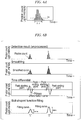
- the particle moves at random in the region as schematically drawn in FIG. 3A .
- the light intensity changes at random as shown in FIG. 3B , which makes it difficult to specify a significant light intensity change corresponding to each particle as the object of observation.
- the excitation light intensity in the light detection region is reduced from the peak at the center of the region toward its outside.
- the profile of the change of the light intensity corresponding to each particle becomes almost uniform in the chronological light intensity data as illustrated in FIG. 4B , and the speed of moving the position of the light detection region is set to be higher than the average moving speed of the particles owing to the Brownian motion (speed of diffusional movement) so that the correspondence between each particle as the object of observation and the light intensity can be easily specified.
- the profile of the change of the light intensity is similar to the excitation light intensity distribution.
- the speed of moving the position of the light detection region may be set to a sufficiently higher value than Vdif.
- Vdif will be 1.0 ⁇ 10 -3 m/s
- supposing Wo is about 0.62 ⁇ m
- the speed of moving the position of the light detection region may be set to about 10 times thereof at 15 mm/s.
- an appropriate speed of moving the position of the light detection region may be determined by repeating preliminary experiments with setting various moving speeds of the position of the light detection region in order to find the condition that the profile of the change of the light intensity becomes an expected profile (typically, similar to the excitation light intensity distribution).
- the change of the light intensity corresponding to the particle in the chronological light intensity data has a profile reflecting the light intensity distribution in the light detection region (light detection region determined by the optical system) (usually, an approximately bell shape) as schematically drawn in FIG. 6A .
- a threshold value Io is set for the light intensity.
- the configuration may be such that, when the time width ⁇ for which the light intensity exceeding the above-mentioned threshold value continues is in a predetermined range, one particle as the object of observation is detected.
- the threshold value Io for the light intensity and the predetermined range for the time width ⁇ are determined based on a profile expected as the intensity of the light emitted from a combined body of a particle as the object of observation and a luminescent probe (or a luminescent probe having been freed from a particle by decomposition after being bound thereto) moving relatively to the light detection region at a predetermined speed.
- the concrete values of the profile may be set experimentally arbitrarily.
- the concrete values of the profile may be selectively determined depending upon the characteristics of a combined body of a particle as the object of observation and a luminescent probe (or a luminescent probe having been freed from a particle by decomposition after being bound thereto).
- the profile of the light intensity may be judged to correspond to one particle as the object of observation having passed through the light detection region, and thereby the detection of one particle as the object of observation will be done. Note that, when the intensity A and the width a are out of the predetermined ranges, the profile of the light intensity may be disregarded as a noise or a contaminant in the analysis.
- the counting of particles as the object of observation may be done by counting in an arbitrary way the number of the particles detected by the above-mentioned method of detection of the particle as the object of observation. However, for a large number of particles, for example, the counting of the particles as the object of observation may be accomplished by the processes illustrated in FIG. 5 and FIG. 6B .
- the smoothing process may be done, for example, by the moving average method.
- parameters in executing the smoothing process may be suitably set in accordance with the moving speed (scanning speed) of the position of the light detection region and/or BIN TIME in the optical signal data acquisition.
- the above-mentioned parameters means, for example, the number of datum points in one time of the averaging, the number of times of moving average, or the like, in the moving average method,
- the primary differentiation value with time of the chronological optical signal data after the smoothing process is computed (S 120).
- the mid-low row "time differential" in FIG. 6B since the change of the value increases at the time when the signal value changes in the time differential value of chronological optical signal data, the start point and the end point of a significant signal (peak signal) can be determined advantageously by referring to the above-mentioned time differential value.
- a significant signal (peak signal) is detected sequentially on the chronological optical signal data, and it is judged whether or not the detected peak signal is a signal corresponding to a particle as the object of observation.
- the time differential value is sequentially referred to.
- the starting point and the end point of one peak signal are searched and determined, by which a peak existence region is specified (S 130).
- the fitting of a bell-shaped function is applied to the smoothed chronological optical signal data in the peak existence region (the lower row "bell-shaped function fitting" in FIG. 6B ), and parameters in the bell-shaped function, such as the peak intensity, Imax; the peak width (full width at half maximum), w; the correlation coefficient in the fitting (correlation coefficient of the least square method), etc. are calculated (S 140).
- the bell-shaped function to be used in the fitting is typically a Gauss function.
- the bell-shaped function to be used in the fitting may also be a Lorentz type function. Then, it is judged whether or not the calculated parameters of the bell-shaped function are within the respective ranges assumed for the parameters of the bell-shaped profile drawn by a light signal detected when one combined body of the particle and the luminescent probe, or one luminescent probe, passes through the light detection region (S 150). That is, in this judgment, it is judged whether or not the peak intensity, the peak width, and the correlation coefficient are respectively within the predetermined ranges.
- the signal whose calculated parameters of the bell-shaped function are judged to be within the ranges assumed in a light signal corresponding to one combined body of the particle and the luminescent probe, or one luminescent probe, as shown in FIG. 7 left, is judged as a signal corresponding to one particle as the object of observation.
- one particle as the object of observation has been detected, and one particle is counted (the number of particles is incremented by one: S 160).
- a peak signal whose computed parameters of the bell-shaped function are not within the assumed ranges, as shown in FIG. 7 right, is disregarded as noise.
- the search and the judgment of a peak signal in the processes of the above-mentioned S 130 to S 160 are repetitively executed in the whole region of the chronological optical signal data, and whenever one particle as the object of observation is detected, it is counted as one particle. And, when the search of the peak signal in the whole region of the chronological optical signal data is completed (S 170), the count value of particles obtained till then is considered as the number of particles as the object of observation detected in the chronological optical signal data.
- the number density or concentration of the particle as the object of observation is determined by using the whole volume of the region which the light detection region has passed through during the acquisition of the chronological optical signal data.
- the effective volume of the light detection region varies depending on the wavelength of excitation light or detected light, the numerical aperture of lenses, and the adjustment condition of the optical system, and therefore, it is generally difficult to compute the effective volume of the light detection region from the design parameter values. Accordingly, it is not easy to compute the whole volume of the region which the light detection region has passed through, either.
- the configuration may be such that the light intensity measurement, the detection of particles, and the counting thereof are performed as described above with a solution having a known concentration of the particles (reference solution) under the same condition as that for the measurement of a sample solution to be tested, so that the whole volume of the region which the light detection region has passed through, i.e., the relation between the detected number and the concentration of the particles as the object of observation, can be determined from the detected number of the particles and the concentration of the particles in the reference solution.
- a solution having a known concentration of the particles reference solution
- the particle of the reference solution may be a light emitting label (fluorescent dye etc.) having the same emission characteristics as those of a combined body of a particle formed of the particle as the object of observation and a luminescent probe (or a luminescent probe freed from the particle as the object of observation after being bound thereto).
- a light emitting label fluorescent dye etc.
- the configuration may also be such that a plurality of solutions having different concentrations are prepared as the reference solutions and the measurement is executed for each of the solutions so that the average value of the computed Vt can be employed as the whole volume Vt of the region which the light detection region has passed through.
- the volume of the light detection region and the whole volume of the region which the light detection region has passed through are given by an arbitrary method instead of the above-mentioned method.
- the whole volume may be given by using FCS and FIDA.
- the configuration may be such that the information on the relations (expression (5)) between the concentrations C and the numbers N of various standard particles for assumed moving patterns of the light detection region are previously stored in a storage device of the computer 18, so that a user of the device can appropriately use the stored information on the relation in conducting photometric analysis.
- the method for detecting a nucleic acid molecule of this embodiment is a method the object of analysis of which is a nucleic acid molecule having a specific base sequence, the method comprising: using a nucleic acid probe which can be specifically bound to the nucleic acid molecule; hybridizing the nucleic acid probe and the nucleic acid molecule to be analyzed (hereunder, may be referred to as a target nucleic acid molecule); and detecting the nucleic acid molecule to be analyzed based on the amount of the thus formed associated bodies. Furthermore, in this embodiment, the detection of the associated bodies is performed by measurement with the above-mentioned scanning molecule counting method.
- the scanning molecule counting method is a measurement method capable of measuring fluorescent particles one by one in a condition where the molecules are spaced and apart from each other, the measurement is possible for nucleic acid molecules whose concentration is relatively low in a pM order or lower. For this reason, with the method for detecting a nucleic acid molecule of this embodiment, even if the concentration of the target nucleic acid molecules in a sample solution is extremely low, the formed associated bodies can be counted with high sensitivity.
- a nucleic acid probe can be specifically bound to a target nucleic acid molecule means that the nucleic acid probe can be preferentially bound to the target nucleic acid molecule rather than other single stranded nucleic acid molecules.
- the target nucleic acid molecule is a single stranded nucleic acid molecule, it means that the nucleic acid probe can preferentially hybridize with the target nucleic acid molecule rather than other single stranded nucleic acid molecules.
- the target nucleic acid molecule is a double stranded nucleic acid molecule
- the nucleic acid probe can preferentially hybridize with one of the two single stranded nucleic acid molecules constituting the target nucleic acid molecule.
- the nucleic acid probe may have a base sequence which is completely complementary to the base sequence of the target nucleic acid molecule, or may have a base sequence which has mismatch(es) against the base sequence of the target nucleic acid molecule.
- This embodiment uses a nucleic acid probe which is specifically hybridizable with the target nucleic acid molecule.
- the target nucleic acid molecule can be detected distinctively from other nucleic acid molecules contained in the biosample. If the target nucleic acid molecule is present in a biosample, the associated body including the nucleic acid probe is detected in a sample solution having a mixture of the biosample and the nucleic acid probe. On the other hand, if the target nucleic acid molecule is not present in the biosample, the associated body including the nucleic acid probe is not detected in the sample solution.
- the nucleic acid probe for use in this embodiment may be an oligonucleotide consisting of DNA.
- the nucleic acid probe may be an oligonucleotide consisting of RNA.
- the nucleic acid probe may be a chimeric oligonucleotide consisting DNA and RNA.
- the nucleic acid probe may be a substance a part or all of which includes a nucleotide chain or a nucleic acid analog which is capable of forming base pairs, similarly to natural nucleic acid bases.
- the nucleic acid analog can be exemplified by; substances in which a side chain etc.
- a natural nucleotide such as DNA or RNA is modified with a functional group such as an amino group etc., substances labeled with a protein, a low molecular compound, etc., and the like.
- the examples of the nucleic acid analog include; bridged nucleic acid (BNA), a nucleotide in which an oxygen atom at the 4' position of a natural nucleotide is substituted with a sulfur atom, a nucleotide in which a hydroxyl group at the 2' position of a natural ribonucleotide is substituted with a methoxy group, a hexitol nucleic acid (HNA), a peptide nucleic acid (PNA), and the like.
- the nucleic acid to be analyzed may be DNA.
- the nucleic acid to be analyzed may be RNA.
- the nucleic acid to be analyzed may be artificially amplified DNA such as cDNA.
- the associated body formed of the nucleic acid probe and the another single stranded nucleic acid molecule and the nucleic acid probe not forming such an associated body can be detected distinctively in the scanning molecule counting method.
- a molecular beacon probe can also be used as the nucleic acid probe.
- the molecular beacon probe is an oligonucleotide which forms an intramolecular structure in a state of the single stranded nucleic acid molecule, and is a probe made by binding a fluorescent substance serving as an energy donor and a substance serving as an energy acceptor in FRET (a fluorescent substance and a quencher substance) so that FRET occurs in the state of the single stranded nucleic acid molecule and FRET does not occur in the state of the associated body formed by hybridization with another single stranded nucleic acid molecule.
- FRET fluorescent substance and a quencher substance
- Fluorescence to be emitted from the fluorescent substance serving as an energy donor is detected from the nucleic acid probe forming the associated body.
- fluorescence to be emitted from the fluorescent substance serving as an energy donor is not detected or is attenuated, from the solely existing nucleic acid probe. Therefore, by detecting the fluorescence emitted from the fluorescent substance serving as an energy donor, the associated body including the nucleic acid probe can be detected distinctively from the solely existing nucleic acid probe.
- the molecular beacon probe for use as the nucleic acid probe can be exemplified by an oligonucleotide having a base sequence which is hybridizable with the target nucleic acid molecule as well as having mutually complementary base sequences in a region on the side of the 3'-end and a region on the side of the 5'-end.
- the molecular beacon probe of this embodiment is bound with a fluorescent substance serving as an energy donor or a substance serving as an energy acceptor on the side of the 3'-end and bound with the other one on the side of the 5'-end, as well as having mutually complementary base sequences in regions on the side of the 3'-end and the side of the 5'-end, and forming an intramolecular structure by forming base pairs between these base sequences (a so-called stem loop structure).
- the mutually complementary regions which form the intramolecular base pairs of the molecular beacon probe may exist so as to interpose the region which is complementary with the target nucleic acid molecule.
- the region on the side of the 3'-end and the region on the side of the 5'-end may respectively include the 3'-end or the 5'-end.
- the region on the side of the 3'-end and the region on the side of the 5'-end may not respectively include the 3'-end or the 5'-end.
- the numbers of bases and the base sequences of the regions forming the base pairs may be at degrees where the stability of the formed base pairs is lower than the stability of the associated body with the nucleic acid molecule, and where the base pairs can be formed under the measurement condition.
- the fluorescent substance is not particularly limited as long as it is a substance which emits fluorescence by irradiation of light of a specific wavelength, and may be used by appropriately selecting from fluorescent dyes for use in FCS, FIDA, and the like.
- the labeling of the nucleic acid probe with the fluorescent substance can be performed by a usual method.
- nucleic acid probe labeled with a fluorescent substance which causes FRET with a fluorescent double stranded nucleic acid-binding substance it is also possible to detect the associated body including the nucleic acid probe distinguishingly from the solely existing luminescent probe. That is, either one of the fluorescent double stranded nucleic acid-binding substance or the fluorescent substance for labeling the nucleic acid probe serves as an energy donor of FRET, and the other one serves as an energy acceptor of this FRET. From the solely existing nucleic acid probe such as a first nucleic acid probe, fluorescence to be emitted from the fluorescent substance for labeling this nucleic acid probe is detected.
- the associated body since the fluorescent double stranded nucleic acid-binding substance is bound to the associated body, fluorescence to be emitted from FRET is detected from the associated body. As a result, the associated body can be detected distinctively from the solely existing nucleic acid probe.
- the fluorescent double stranded nucleic acid-binding substance which can be specifically bound to a double stranded chain structure
- a fluorescent intercalator a group binder bound with a fluorescent substance, and the like. If the amount of the fluorescent intercalator to be inserted between the base pairs of the associated body is too large, the background for detecting the fluorescence emitted from FRET becomes so high that the detection precision might be influenced. For this reason, it is preferable to design the nucleic acid probe so that the region for forming the double strand in the associated body is 400 bp or shorter.
- the target nucleic acid molecule can also be detected by using two types of nucleic acid probes.
- two types of nucleic acid probes are designed so that they can be hybridized specifically with the target nucleic acid molecule in mutually adjacent positions.
- one nucleic acid probe is labeled with a fluorescent substance
- the other nucleic acid probe is labeled with a fluorescent substance which causes FRET with the fluorescent substance being labeled onto the former nucleic acid probe, or a quencher substance.
- the associated body including the nucleic acid probes can be detected distinctively from the solely existing nucleic acid probes.
- the method for detecting a nucleic acid molecule of this embodiment concretely comprises the following steps (a) to (c), and has a step for removing proteins from the following sample solution before the following step (c), or a step for removing proteins from the following biosample before the following step (a):
- the step (a) is to prepare a sample solution containing a nucleic acid probe and a biosample.
- the nucleic acid probe and the biosample are added to an appropriate solvent to prepare the sample solution.
- This solvent is not particularly limited as along as it is a solvent as explained below, and the solvent can be used by appropriately selecting from buffers for usual use in this technical field. That is, the solvent suffices if it does not interfere with the formation of the associated body by the nucleic acid probe, and the detection of the associated body by the scanning molecule counting method.
- This buffer can be exemplified by phosphate buffers such as PBS (phosphate buffered saline, pH 7.4), Tris buffer, and the like.
- the fluorescent double stranded nucleic acid-binding substance which can be specifically bound to a double stranded structure is used for the detection of the associated body including the nucleic acid probe
- the fluorescent double stranded nucleic acid-binding substance is added to the sample solution, similarly to the nucleic acid probe and the like.
- the biosample to be supplied in this embodiment can be exemplified by tissue pieces collected from a biological body. Specific examples can be given by: body fluids such as blood, lymph fluid, bone marrow fluid, ascitic fluid, exudative fluid, amniotic fluid, expectorated sputum, saliva, semen, bile, pancreatic fluid, and urine; tissue pieces collected from a biological body; feces, intestinal lavage fluid, lung lavage fluid, bronchial lavage fluid, bladder lavage fluid, or the like. Moreover, the biosample may be a cellular component separately collected from cells.
- body fluids such as blood, lymph fluid, bone marrow fluid, ascitic fluid, exudative fluid, amniotic fluid, expectorated sputum, saliva, semen, bile, pancreatic fluid, and urine
- tissue pieces collected from a biological body feces, intestinal lavage fluid, lung lavage fluid, bronchial lavage fluid, bladder lavage fluid, or
- the cellular component can be exemplified by plasma, serum, or the like, separately collected from blood.
- the biosample may also be a sample prepared by paraffin embedding of a tissue piece collected from a biological body, and thereafter deparaffinizing the thus produced paraffin block or a section thereof. Note that, the collection from a biological body, the centrifugal treatment, the chromatography method, the paraffin embedding, and the deparaffinization can be performed by usual methods.
- the biosample may be previously applied with a proteinase treatment.
- the proteinase can be exemplified by proteinase K or the like.
- a treatment to inactivate the enzyme is conducted after the enzymatic reaction.
- the enzymatic reaction is performed at 50 to 60°C for 30 minutes to several hours, and thereafter the inactivation treatment is performed at 70°C for 5 to 15 minutes.
- the inactivation treatment can be omitted.
- the step (b) is to associate the nucleic acid molecules in the sample solution having been prepared in the step (a).
- the nucleic acid molecules in the sample solution are double stranded nucleic acid molecules, it is preferable to denature the nucleic acids before making them associate.
- the phrase "to denature a nucleic acid molecule” means to dissociate the base pairs.
- it means to dissociate the base pairs formed by the mutually complementary base sequences in a single stranded nucleic acid molecule to open the intramolecular structure to be in a single stranded structure, or to separate a double stranded nucleic acid molecule into single stranded nucleic acid molecules.
- the nucleic acid probe is an oligonucleotide including a nucleic acid analog such as PNA, it may be possible in some cases to form the associated body including the nucleic acid probe without performing a special denaturation treatment, even if the nucleic acid molecules are double stranded nucleic acid molecules.
- heat denaturation is capable of denaturing nucleic acid molecules in this sample solution by treating this sample solution with high temperature.
- the denaturation of DNA can be done by keeping the temperature at 90°C for about several seconds to two minutes.
- the denaturation of RNA can be done by keeping the temperature at 70°C for about several seconds to two minutes.
- the temperature for denaturing the nucleic acid molecules is multifarious depending on the base length of the target nucleic acid molecule etc., and it is not to be limited to the above-mentioned temperatures as long as the denaturation is possible.
- the denaturation by means of a low salt concentration treatment can be performed by adjustment by means of dilution with, for example, purified water or the like, so that the salt concentration of this sample solution can be sufficiently low.
- the nucleic acid molecules in the sample solution are associated with each other. If the heat denaturation has been performed, the nucleic acid molecules in this sample solution can be suitably associated with each other by lowering the temperature of this sample solution to a temperature at which the nucleic acid probe and the target nucleic acid molecule can specifically hybridize with each other, after the high temperature treatment. Moreover, if the denaturation by means of a low salt concentration treatment has been performed, the nucleic acid molecules in this sample solution can be suitably associated with each other by raising the salt concentration of this sample solution to a concentration at which the nucleic acid probe and the target nucleic acid molecule can specifically hybridize with each other, by adding a salt solution or the like.
- the temperature at which the nucleic acid probe and the target nucleic acid molecule can specifically hybridize with each other can be obtained from the melting curve of the associated body consisting of the target nucleic acid molecule and the nucleic acid probe.
- the melting curve can be obtained by, for example, changing the temperature of a solution containing only the nucleic acid probe and the target nucleic acid molecule from a high temperature to a low temperature, and measuring the absorbance or the fluorescence intensity of this solution.
- a temperature within a range from the temperature at which the denatured nucleic acid probe and target nucleic acid molecule start to form an associated body to the temperature at which almost all of them have formed associated bodies can be set as the temperature at which the nucleic acid probe and the target nucleic acid molecule can specifically hybridize with each other.
- the concentration at which the nucleic acid probe and the target nucleic acid molecule can specifically hybridize with each other can be obtained by determining the melting curve by changing the salt concentration in the solution from a low concentration to a high concentration in the same manner.
- the temperature at which the nucleic acid probe and the target nucleic acid molecule can specifically hybridize with each other can be generally substituted with a Tm value (melting temperature).
- Tm value melting temperature
- the Tm value of the region which is hybridizable with the target nucleic acid molecule can be calculated from the base sequence information of the nucleic acid probe by using a usual primer/probe design software etc.
- the temperature of the sample solution is lowered to about a temperature at Tm value ⁇ 3°C of the region in the nucleic acid probe having a base sequence which is complementary to the target nucleic acid molecule.
- the temperature of the sample solution for forming the associated body so as to suppress non-specific hybridization.
- the liquid temperature of this sample solution can be lowered at a cooling rate of 0.05°C/sec. or quicker.
- a surfactant such as a surfactant, formamide, dimethyl sulfoxide, urea, or the like, in the sample solution prior to the step (c).
- a single type of, or a combination of two or more types of, these compounds may be added. By adding these compounds, non-specific hybridization can be less likely to occur under a relatively low temperature environment.
- These compounds may be contained in the sample solution when preparing the sample solution in the step (a). Moreover, these compounds may also be added to the sample solution after the step (b) and before the step (c).
- Various impurities such as proteins having autofluorescence contained in a biosample may be a cause of the occurrence of non-specific signals or hindering against the optical path of transmission in the measurement by the scanning molecule counting method.
- the measurement by the scanning molecule counting method in the step (c) is conducted in a condition where biosample-derived proteins have been removed, the influences of the biosample-derived impurities are remarkably suppressed and the target nucleic acid molecule at a low concentration can be detected with good precision.
- the removal of the biosample-derived proteins may be conducted before the measurement by the scanning molecule counting method in the step (c).
- the sample solution may be prepared by mixing a biosample, to which a protein removal treatment has been applied after the collection from a biological body, with the nucleic acid probe in the step (a).
- the protein removal treatment may be applied to the sample solution after the step (a) and before the step (b).
- the protein removal treatment may also be applied to the sample solution after the step (b) and before the step (c).
- this embodiment is capable of saving the labor and time for preparing the sample, it is preferable to apply the protein removal treatment to the sample solution in the following cases, and it is more preferable to apply the protein removal treatment to the sample solution after the step (a) and before the step (b):
- the protein removal treatment can be adopted by appropriately selecting from among methods known in this technical field.
- the deproteinized biosample etc. can be obtained by contacting; the biosample before mixing with the nucleic acid probe, the sample solution prepared in the step (a), or the sample solution after the step (b) (hereunder, referred to as the biosample etc.), with an inorganic support so as to thereby adsorb nucleic acid molecules contained in the biosample etc. to the inorganic support, and thereafter eluting the adsorbed nucleic acid molecules from the inorganic support.
- the inorganic support a known inorganic support capable of adsorbing nucleic acid molecules can be used.
- the shape of the inorganic support is not particularly limited, and it may be a particulate form or a membrane form.
- the inorganic support can be exemplified by: silica-containing particles (beads) of silica gel, siliceous oxide, glass, diatomite, etc.; porous membranes of nylon, polycarbonate, polyacrylate, nitrocellulose, etc.; or the like.
- the solvent for eluting the adsorbed nucleic acid molecules from the inorganic support a solvent for usual use in eluting nucleic acid molecules from such a known inorganic support can be appropriately used.
- the eluting solvent is purified water. Note that, it is preferable that the inorganic support having the nucleic acid molecules adsorbed thereto is washed with an appropriate washing buffer, and thereafter the nucleic acid molecules are eluted from the inorganic support.
- the proteins contained in the biosample etc. may be denatured before conducting the protein removal treatment.
- the protein denaturation can be conducted by a known method.
- the proteins in the biosample etc. can be denatured by adding a compound usually used as a protein denaturant such as a chaotropic salt, an organic solvent, a surfactant, or the like, to the biosample etc.
- a compound usually used as a protein denaturant such as a chaotropic salt, an organic solvent, a surfactant, or the like
- a chaotropic salt an organic solvent, a surfactant, or the like
- one type, or two or more types of compounds may be added.
- the surfactant that can be contained in the biosample etc. is preferably a nonionic surfactant.
- the nonionic surfactant can be exemplified by Tween 80, CHAPS (3-[3-cholamidopropyldimethylammonium]-1-propanesulfonate), Triton X-100, Tween 20, and the like.
- the organic solvent that can be contained in the biosample etc. is preferably a phenol.
- the phenol may be either neutral or acidic. In a case of using an acidic phenol, RNA can be selectively extracted in the water phase rather than DNA.
- the denatured proteins can be removed, for example, by centrifugation so as to precipitate the denatured proteins, and collecting the supernatant alone. Moreover, the denatured proteins can be more entirely removed rather than simply conducting the centrifugation, by adding chloroform, sufficiently mixing them by agitation with a vortex or the like, thereafter conducting centrifugation so as to precipitate the denatured proteins, and collecting the supernatant alone.
- the obtained supernatant may also be applied with an additional protein removal treatment by contacting it with the above-mentioned inorganic support.
- the biosample is a type of biosample whose protein content is relatively low such as plasma, serum, or the like
- proteins can be removed by aggregating the proteins using a deproteinization agent, and thereafter collecting the liquid component through a solid-liquid separation treatment.
- the deproteinization agent is added to the biosample, then the mixture is agitated or left still to thereby aggregate the proteins, thereafter a centrifugation treatment is conducted, and the supernatant is collected.
- the deproteinization agent for example, an ion-exchange resin or such a highly affinitive substance to proteins can be used.
- the number of molecules of the associated bodies including the nucleic acid probe in the sample solution is counted by the scanning molecule counting method.
- the sample solution after forming the associated bodies is set in the above-mentioned photometric analysis device for the scanning molecule counting method, and fluorescence emitted from the associated bodies is detected and analyzed by the above-mentioned technique, by which the number of molecules of the associated bodies is calculated.
- the calculated number of molecules of the associated bodies is the number of the target nucleic acid molecules contained in the measurement sample. That is, the target nucleic acid molecule can be detected by detecting the associated body.
- Test Example 1 artificially synthesized oligonucleotides were used as the single stranded target nucleic acid molecule and the nucleic acid probe, samples produced by adding them to an equine whole blood or an equine plasma were used as biosample-simulating samples, and the target nucleic acid molecule in the simulated biosamples was detected by the scanning molecule counting method.
- the base sequences of the target nucleic acid molecule A and the nucleic acid probe A used for the measurement are shown in Table 1.
- the nucleic acid probe A is the molecular beacon probe.
- the underlined bases are regions which are hybridized with each other when forming the intramolecular structure.
- Base sequences Nucleic acid probe A 1 Target nucleic acid molecule A 2
- a 50 pM nucleic acid probe solution was prepared by mixing the target nucleic acid molecule A and the nucleic acid probe A respectively at 50 pM in Tris buffer (10 mM Tris-HCl, 1 mM EDTA, 100 mM NaCl, and pH 8.0). Moreover, a 5 pM nucleic acid probe solution was prepared by mixing the target nucleic acid molecule A and the nucleic acid probe A respectively at 5 pM in the above-mentioned Tris buffer.
- the obtained nucleic acid probe solutions were subjected to an annealing treatment at 95°C for 10 minutes, 70°C for 10 minutes, 60°C for 10 minutes, 50°C for 10 minutes, and 20°C for 10 minutes, to thereby form the associated body consisting of the target nucleic acid molecule A and the nucleic acid probe A.
- a nucleic acid extraction liquid was prepared from 50 ⁇ l of equine whole blood or 50 ⁇ l of equine plasma with use of the nucleic acid extraction kit (product name: QIAamp DNA Micro kit, manufactured by QIAGEN).
- the nucleic acid extraction liquid corresponds to the biosample after the protein removal treatment in the embodiment of the present invention.
- the equine whole blood or the equine plasma before the treatment using the nucleic acid extraction kit corresponds to the biosample before the protein removal treatment in the embodiment of the present invention.
- Respectively 50 ⁇ l of the 50 pM nucleic acid probe solution or the 5 pM nucleic acid probe solution after the annealing treatment was added to the prepared nucleic acid extraction liquids, by which sample solutions were prepared (Sample preparation (+)).
- sample preparation (+) Respectively 50 ⁇ l of the 50 pM nucleic acid probe solution or the 5 pM nucleic acid probe solution after the annealing treatment was added to 50 ⁇ l of the equine whole blood and the 50 ⁇ l of the equine plasma, by which sample solutions were prepared.
- control respectively 50 ⁇ l of the 50 pM nucleic acid probe solution or the 5 pM nucleic acid probe solution after the annealing treatment was added to 50 ⁇ l of the above-mentioned Tris buffer, by which sample solutions were prepared (Control).
- Test Example 1 the number of molecules of the associated bodies consisting of the target nucleic acid molecules A and the nucleic acid probes A in each sample solution was counted by the scanning molecule counting method.
- a single molecule fluorescence measuring apparatus MF-20 (Olympus Corporation), equipped with the optical system of a confocal fluorescence microscope and a photon counting system was used as the photometric analysis device, to obtain the chronological photon count data of the above-mentioned respective sample solutions.
- 543 nm laser light was used for excitation light and irradiated at 300 ⁇ W with a rotation speed of 6,000 rpm.
- the detected light wavelength was set from 560 to 620 nm using a band pass filter.
- BIN TIME was set to 10 ⁇ sec and the measuring time was set to 2 seconds.
- the chronological data obtained by the measurement were smoothed by the Savinzky-Golay algorithm, and then peaks were detected by differentiation. Among the regions regarded as peaks, regions which were able to be approximated to the Gauss function were extracted as signals.
- each concentration shows the concentration of the target nucleic acid molecule A in each sample solution.
- the number of peaks counted in the sample solution having no biosample (Control) is the reliable counting result without being influenced by biosample-derived impurities.
- the number of peaks was remarkably larger than that of the sample solution (Control) irrespective of the number of the target nucleic acid molecules in the sample solution for both blood and plasma. This can be attributed to the impurities in the biosample which had brought about the occurrence of non-specific signals in the measurement by the scanning molecule counting method and had increased the peaks.
- Example 1 among PCR products obtained by PCR using a fluorescently labeled primer and a non-labeled primer, the single stranded nucleic acid molecule extended from the non-labeled primer was used as the target nucleic acid.
- the single stranded nucleic acid molecule extended from the fluorescently labeled primer was used as the nucleic acid probe.
- a sample made by adding them to a biosample obtained by deparaffinizing a paraffin-embedded tissue section was used as the simulated biosample, and the target nucleic acid molecule in a simulated biosample was detected by the scanning molecule counting method.
- Example 1 a PCR product having a chain length of 800bp was prepared by using plasmid pUC19 (manufactured by TAKARA BIO INC.) as a template, a TAMRA-labeled oligonucleotide primer, an oligonucleotide primer not labeled with any fluorescent substance, and a PCR kit (product name: AmpliTaq Gold, manufactured by Applied Biosystems).
- the unreacted oligonucleotide primers were removed from the PCR product by using Wizard SV Gel and PCR Clean-Up System (manufactured by Promega Corporation).
- PCR product solutions were respectively prepared by using Tris buffer (10 mM Tris-HCl, 1 mM EDTA, 100 mM NaCl, and pH 8.0) so that the concentration of the PCR product would be 2 pM, 20 pM, or 200 pM.
- the fluorescently-labeled nucleic acid molecule was used as the nucleic acid probe B, and the non-fluorescently-labeled nucleic acid molecule was used as the target nucleic acid molecule B.
- Example 1 4% formalin-fixed paraffin-embedded tissue sections of rat liver and kidney were deparaffinized with xylene, and then proteinase K was added thereto to conduct an enzymatic reaction treatment at 56°C for 10 minutes.
- the solution after the enzymatic reaction treatment was regarded as the proteinase K-treated biosample solution.
- the proteinase K-treated biosample solution was added with an equal amount of the PCR product solution of respective concentrations or the Tris buffer, by which sample solutions having PCR product concentrations at 0, 1, 10, and 100 pM were respectively prepared (without protein removal treatment). Furthermore, the respective sample solutions were subjected to an annealing treatment by heating at 95°C for 10 minutes and 55°C for 10 minutes, and then keeping at room temperature.
- the proteinase K-treated biosample solution was additionally treated at 70°C for 10 minutes, and then was added with an equal amount of the PCR product solution or the Tris buffer, by which sample solutions having PCR product concentrations at 0, 1, 10, and 100 pM were respectively prepared. Furthermore, the respective sample solutions were subjected to an annealing treatment in the same way as that for the sample solutions (without protein removal treatment). Then, the sample solutions after the annealing treatment were purified by using a nucleic acid purification kit (product name: MinElute PCR purification kit, manufactured by QIAGEN), and the thus obtained nucleic acid extraction liquids were used as the measurement samples (with protein removal treatment 1).
- a nucleic acid purification kit product name: MinElute PCR purification kit, manufactured by QIAGEN
- the proteinase K-treated biosample solution without the treatment at 70°C for 10 minutes was added with an equal amount of the PCR product solution of respective concentrations or the Tris buffer, by which sample solutions having PCR product concentrations 0, 1, 10, and 100 pM were respectively prepared. Furthermore, the respective sample solutions were subjected to an annealing treatment in the same way as that for the sample solutions (with protein removal treatment 1) and then purified by using the nucleic acid purification kit, and the thus obtained nucleic acid extraction liquids were used as the measurement samples (with protein removal treatment 2).
- the PCR product solution of respective concentrations or the Tris buffer were added at equal amounts, by which sample solutions having PCR product concentrations at 0, 1, 10, and 100 pM were respectively prepared (Control). Furthermore, the respective sample solutions were subjected to an annealing treatment in the same way as that for the sample solutions (without protein removal treatment).
- Example 1 the number of the associated bodies consisting of the target nucleic acid molecule B and the nucleic acid probe B existing in each of the above-mentioned supernatants was counted by the scanning molecule counting method in the same manner as that of Test Example 1.
- the counting results are shown in FIG. 9 and Table 3. Furthermore, in FIG. 9 , the approximation straight lines regarding the relation between the concentration of the target nucleic acid molecule in each sample solution and the counted number of peaks are shown in Table 4.
- the number of peaks counted in the sample solution having no biosample (Control) is the reliable counting result without being influenced by biosample-derived impurities.
- the sample solution (without protein removal treatment) showed extremely high values as compared to those of the sample solution (Control). Moreover, the relation between the concentration of the target nucleic acid molecule in the sample solution and the detected number of peaks remarkably lacked the linearity as compared to the sample solution (Control).
- the method for detecting a nucleic acid molecule is capable of measurement by the scanning molecule counting method even if the enzyme deactivation treatment or the like is omitted.
- Example 2 among PCR products obtained by PCR using a fluorescently labeled primer and a non-labeled primer, the single stranded nucleic acid molecule extended from the non-labeled primer was used as the target nucleic acid.
- the single stranded nucleic acid molecule extended from the fluorescently labeled primer was used as the nucleic acid probe.
- a sample made by adding them to an equine plasma was used as the simulated biosample, and the target nucleic acid molecule in the simulated biosample was detected by the scanning molecule counting method.
- Example 2 a PCR product having a chain length of 800bp was prepared by using plasmid pUC19 (manufactured by TAKARA BIO INC.) as a template, an ATTO 647N-labeled oligonucleotide primer, an oligonucleotide primer not labeled with any fluorescent substance, and a PCR kit (product name: AmpliTaq Gold, manufactured by Applied Biosystems).
- the unreacted oligonucleotide primers were removed from the PCR product by using Wizard SV Gel and PCR Clean-Up System (manufactured by Promega Corporation).
- PCR product solutions were respectively prepared by using Tris buffer (10 mM Tris-HCl, 1 mM EDTA, 100 mM NaCl, and pH 8.0) so that the concentration of the PCR product would be 2 pM, 20 pM, or 200 pM.
- the fluorescently-labeled nucleic acid molecule was used as the nucleic acid probe C, and the non-fluorescently-labeled nucleic acid molecule was used as the target nucleic acid molecule C.
- Example 2 in a 1.5 ml tube were added equal amounts of the equine plasma and the PCR product solution of 2 pM, 20 pM, or 200 pM having been prepared in Example 1 or the Tris buffer, so that two 100 ⁇ l of sample solutions are prepared for each of those having PCR product concentrations at 0, 1, 10, and 100 pM respectively.
- Example 2 the number of the associated bodies consisting of the target nucleic acid molecule C and the nucleic acid probe C existing in each of the above-mentioned supernatants was counted by the scanning molecule counting method in the same manner as that of Test Example 1, except for that the 633 nm laser light was used for excitation light, and the detected light wavelength was set from 660 to 710 nm using a band pass filter.
- the counting results are shown in FIG. 10 and Table 5.
- the term “without removal” shows the results of the sample solution to which PBS had been added instead of the deproteinization agent (without protein removal treatment).
- the term “with removal” shows the results of the sample solution to which the deproteinization agent had been added (with protein removal treatment).
- the concentration shows the concentration of the target nucleic acid molecule in each sample solution.
- a biosample-derived nucleic acid molecule which exists only at a very low concentration in a sample solution can be detected by the scanning molecule counting method, by having them emit light with use of a probe which is specifically hybridizable with the nucleic acid molecule. For this reason, this method is applicable to fields such as a clinical test for detecting a nucleic acid molecule in a biosample.
Landscapes
- Chemical & Material Sciences (AREA)
- Physics & Mathematics (AREA)
- Health & Medical Sciences (AREA)
- Life Sciences & Earth Sciences (AREA)
- Immunology (AREA)
- Analytical Chemistry (AREA)
- Organic Chemistry (AREA)
- Biochemistry (AREA)
- General Health & Medical Sciences (AREA)
- General Physics & Mathematics (AREA)
- Proteomics, Peptides & Aminoacids (AREA)
- Engineering & Computer Science (AREA)
- Zoology (AREA)
- Wood Science & Technology (AREA)
- Spectroscopy & Molecular Physics (AREA)
- Pathology (AREA)
- Nuclear Medicine, Radiotherapy & Molecular Imaging (AREA)
- Molecular Biology (AREA)
- Microbiology (AREA)
- Biophysics (AREA)
- Biotechnology (AREA)
- Bioinformatics & Cheminformatics (AREA)
- General Engineering & Computer Science (AREA)
- Genetics & Genomics (AREA)
- Optics & Photonics (AREA)
- Dispersion Chemistry (AREA)
- Chemical Kinetics & Catalysis (AREA)
- Investigating, Analyzing Materials By Fluorescence Or Luminescence (AREA)
- Measuring Or Testing Involving Enzymes Or Micro-Organisms (AREA)
Claims (13)
- Verfahren zum Detektieren einer Nukleinsäure, umfassend:einen Schritt des Herstellens einer Probenlösung, die (i) eine Bioprobe mit dem zu detektierenden Nukleinsäuremolekül und (ii) eine Nukleinsäuresonde, die mit dem zu detektierenden Nukleinsäuremolekül hybridisierbar ist, enthält,einen Schritt des Assoziierens des Nukleinsäuremoleküls mit der Nukleinsäuresonde in der Probenlösung, die in dem Herstellungsschritt hergestellt worden ist; undanschließend zum Assoziierungsschritt, einen Schritt zum Berechnen der Anzahl an assoziierten Körpern, die die mit dem Nukleinsäuremolekül in der Probenlösung, die in dem Herstellungsschritt hergestellt worden ist,hybridisierte Nukleinsäuresonde umfassen;wobei das Verfahren durchgeführt wird durch:einen Schritt des Bewegens der Position eines Lichtdetektierungsbereichs eines optischen Systems eines konfokalen Mikroskops oder eines Multiphotonenmikroskops in der Probenlösung;einen Schritt zum Detektieren von von den assoziierten Körpern emittierter Fluoreszenz in dem Lichtdetektionsbereich während des Bewegens der Position des Lichtdetektionsbereichs des optischen Systems in der Probenlösung;individuelles Detektieren eines Lichtsignals von jedem der jeweiligen assoziierten Körper,dadurch individuelles Detektieren der assoziierten Körper; undder Berechnungsschritt einen Schritt zum Zählen der Anzahl der individuell detektierten assoziierten Körper von den detektierten Lichtsignalen, die während des Bewegens der Position des Lichtdetektierungsbereichs detektiert wurden, umfasst;wobei Proteine aus der Probenlösung vor dem Berechnungsschritt entfernt werden, oder Proteine aus der Bioprobe vor dem Herstellungsschritt entfernt werden.
- Verfahren zum Detektieren eines Nukleinsäuremoleküls nach Anspruch 1, umfassend einen Schritt des Entfernens von Proteinen aus der Probenlösung nach dem Assoziierungsschritt und vor dem Berechnungsschritt.
- Verfahren zum Detektieren eines Nukleinsäuremoleküls nach einem von Anspruch 1 oder Anspruch 2, wobei das Entfernen von Proteinen aus der Probenlösung der Bioprobe durch Adsorbieren von Nukleinsäuremolekülen in der Probenlösung oder der Bioprobe an einen anorganischen Träger durchgeführt wird, und danach Eluieren der adsorbierten Nukleinsäuremoleküle von dem anorganischen Träger.
- Verfahren zum Detektieren eines Nukleinsäuremoleküls nach einem beliebigen von Anspruch 1 bis Anspruch 3, wobei die Bioprobe mit einer Proteinase behandelt wird, nachdem sie aus einem biologischen Körper gesammelt wurde.
- Verfahren zum Detektieren eines Nukleinsäuremoleküls nach einem beliebigen von Anspruch 1 bis Anspruch 4, wobei die Nukleinsäuresonde mit einer Fluoreszenzsubstanz markiert ist.
- Verfahren zum Detektieren eines Nukleinsäuremoleküls nach einem beliebigen von Anspruch 1 bis Anspruch 4, wobei:die Nukleinsäuresonde mit einer Fluoreszenzsubstanz markiert ist;eine fluoreszierende doppelsträngige Nukleinsäure bindende Substanz des Weiteren in der Probenlösung in dem Herstellungsschritt enthalten ist;eine der die Nukleinsäuresonde markierenden Fluoreszenzsubstanz und der fluoreszierenden doppelsträngige Nukleinsäure bindenden Substanz eine Fluoreszenzsubstanz ist, die als Energiedonor in einem Fluoreszenz-Energie-Transfer-Phänomen dient, und die andere eine Substanz ist, die als ein Energieakzeptor in dem Fluoreszenz-Energie-Transfer-Phänomen dient; undin dem Berechnungsschritt die von dem die Nukleinsäuresonde einschließenden, assoziierten Körper emittierte Fluoreszenz Fluoreszenz ist, die aus dem Fluoreszenz-Energie-Transfer-Phänomen emittiert wird, das zwischen der die Nukleinsäuresonde markierenden Fluoreszenzsubstanz und der fluoreszierenden doppelsträngige Nukleinsäure bindenden Substanz auftritt.
- Verfahren zum Detektieren eines Nukleinsäuremoleküls nach einem beliebigen von Anspruch 1 bis Anspruch 4, wobei:Die Nukleinsäuresonde mit einer Fluoreszenzsubstanz gebunden ist, die als ein Energiedonor dient, und einer Substanz, die als ein Energieakzeptor dient, so dass Fluoreszenzenergietransfer in einem Stadium stattfindet, in dem die Nukleinsäuresonde allein existiert, und der Fluoreszenzenergietransfer nicht in einem Stadium stattfindet, in dem die Nukleinsäuresonde einen assoziierten Körper mit einem anderen einzelsträngigen Nukleinsäuremolekül bildet;und die von dem assoziierten Körper emittierte Fluoreszenz, einschließlich der Nukleinsäuresonde, Fluoreszenz ist, die von der als Energiedonor dienenden Fluoreszenzsubstanz emittiert wird.
- Verfahren zum Detektieren eines Nukleinsäuremoleküls nach einem beliebigen von Anspruch 1 bis Anspruch 7, wobei die Position des Lichtdetektionsbereichs bei einer vorbestimmten Geschwindigkeit in dem Schritt zum Bewegen der Position des Lichtdetektionsbereichs bewegt wird.
- Verfahren zum Detektieren eines Nukleinsäuremoleküls nach einem beliebigen von Anspruch 1 bis Anspruch 8, wobei die Position des Lichtdetektionsbereichs in dem Schritt zum Bewegen der Position des Lichtdetektionsbereichs bei einer Geschwindigkeit bewegt wird, die höher ist als die Geschwindigkeit einer Diffusionsbewegung der assoziierten Körper ist.
- Verfahren zum Detektieren eines Nukleinsäuremoleküls nach einem beliebigen von Anspruch 1 bis Anspruch 9, wobei es detektiert wird, dass ein assoziierter Körper den Lichtdetektierungsbereich betreten hat, basierend auf der Form eines chronologisch detektierten Lichtsignals in dem Schritt zum individuellen Detektieren des assoziierten Körpers durch individuelles Detektieren eines Lichtsignals von einem jeweiligen assoziierten Körper von dem detektierten Licht.
- Verfahren zum Detektieren eines Nukleinsäuremoleküls nach einem beliebigen von Anspruch 1 bis Anspruch 10, wobei die Probelösung eine oder mehrere Arten von Substanzen enthält, ausgewählt aus der Gruppe bestehend aus einem oberflächenaktiven Mittel, Formamid, Dimethylsulfoxid und Harnstoff.
- Verfahren zum Detektieren eines Nukleinsäuremoleküls nach einem beliebigen von Anspruch 1 bis Anspruch 11, wobei der Assoziierungsschritt nach dem Denaturieren der Nukleinsäuremoleküle in der Probenlösung durch Einstellen der Temperatur der in dem Herstellungsschritt hergestellten Probenlösung auf 70 °C oder höher, Assoziieren der Nukleinsäuremoleküle in der Probenlösung durch Senken der Flüssigkeitstemperatur der Probenlösung bei einer Abkühlrate von 0,05 °C/Sek oder schneller durchgeführt wird.
- Verfahren zum Detektieren eines Nukleinsäuremoleküls nach einem beliebigen von Anspruch 1 bis Anspruch 12, wobei die Nukleinsäuresonde ein Binden von zwei oder mehr Molekülen, ausgewählt aus der Gruppe bestehend aus DNA, RNA, und einem Nukleinsäureanalog umfasst.
Applications Claiming Priority (2)
| Application Number | Priority Date | Filing Date | Title |
|---|---|---|---|
| JP2011094293 | 2011-04-20 | ||
| PCT/JP2012/060334 WO2012144485A1 (ja) | 2011-04-20 | 2012-04-17 | 生体試料中の核酸分子の検出方法 |
Publications (3)
| Publication Number | Publication Date |
|---|---|
| EP2700934A1 EP2700934A1 (de) | 2014-02-26 |
| EP2700934A4 EP2700934A4 (de) | 2014-11-05 |
| EP2700934B1 true EP2700934B1 (de) | 2016-12-14 |
Family
ID=47041591
Family Applications (1)
| Application Number | Title | Priority Date | Filing Date |
|---|---|---|---|
| EP12773621.3A Not-in-force EP2700934B1 (de) | 2011-04-20 | 2012-04-17 | Verfahren zur erkennung von einem nukleinsäuremolekül in einer biologischen probe |
Country Status (5)
| Country | Link |
|---|---|
| US (1) | US20140093874A1 (de) |
| EP (1) | EP2700934B1 (de) |
| JP (1) | JP6013327B2 (de) |
| CN (1) | CN103608663B (de) |
| WO (1) | WO2012144485A1 (de) |
Family Cites Families (34)
| Publication number | Priority date | Publication date | Assignee | Title |
|---|---|---|---|---|
| JPH04337446A (ja) | 1991-05-15 | 1992-11-25 | Hitachi Ltd | 微粒子計測方法、定量方法および微粒子計測装置 |
| JP3575633B2 (ja) | 1994-12-27 | 2004-10-13 | 株式会社島津製作所 | 核酸合成法 |
| JP2965131B2 (ja) | 1995-07-07 | 1999-10-18 | 東洋紡績株式会社 | 核酸結合用磁性担体およびそれを用いる核酸単離方法 |
| EP0836090A1 (de) | 1996-10-12 | 1998-04-15 | Evotec BioSystems GmbH | Probenanalyseverfahren durch Bestimmung der spezifischen Helligkeitsverteilung von Teilchen |
| US6214565B1 (en) * | 1998-10-09 | 2001-04-10 | The Regents Of The University Of California | Assay for disease related conformation of a protein and isolating same |
| US6782297B2 (en) * | 2001-05-24 | 2004-08-24 | Eric Paul Tabor | Methods and apparatus for data smoothing |
| CA2451614C (en) * | 2001-06-25 | 2011-01-04 | Georgia Tech Research Corporation | Dual resonance energy transfer nucleic acid probes |
| CN100487116C (zh) * | 2001-07-09 | 2009-05-13 | 旭化成株式会社 | 应用非织造织物纯化和检测核酸的方法 |
| US20030092090A1 (en) * | 2001-11-14 | 2003-05-15 | Kiamars Hajizadeh | Rapid prion-detection device, system, and test kit |
| JP2005098876A (ja) | 2003-09-25 | 2005-04-14 | Institute Of Physical & Chemical Research | 2成分相互作用分析方法 |
| US20050287616A1 (en) * | 2004-06-29 | 2005-12-29 | Gross Adam F | Method of assaying denaturation of proteins |
| US20070099227A1 (en) * | 2004-10-12 | 2007-05-03 | Curry Bo U | Significance analysis using data smoothing with shaped response functions |
| JP2006187221A (ja) | 2005-01-04 | 2006-07-20 | Toyobo Gene Analysis:Kk | 全血試料の前処理方法及び核酸増幅方法 |
| MX2007009124A (es) * | 2005-01-31 | 2007-10-08 | Univ Illinois | Metodos y dispositivos para caracterizar particulas en medios transparentes y turbios. |
| JP4757103B2 (ja) | 2005-06-13 | 2011-08-24 | 学校法人関西文理総合学園 | 試料中のウイルスを検出する方法およびシステム |
| US7919242B2 (en) * | 2005-06-30 | 2011-04-05 | Roche Molecular Systems, Inc. | Light emission modifiers and their uses in nucleic acid detection, amplification and analysis |
| EP1906172A4 (de) * | 2005-07-15 | 2014-01-08 | Olympus Corp | Lichtmessgerät |
| JP5473202B2 (ja) * | 2006-10-13 | 2014-04-16 | 滋賀県 | 試料中の蛍光性物質を検出する方法およびシステム |
| WO2008080417A1 (en) | 2006-12-28 | 2008-07-10 | Flult Biosystems Gmbh | A method of determining characteristic properties of a sample containing particles |
| JP2008292371A (ja) | 2007-05-25 | 2008-12-04 | Institute Of Physical & Chemical Research | 蛍光相関分光による複数成分相互作用の分析方法及び相互作用制御化合物のスクリーニング方法 |
| JP2011508219A (ja) * | 2007-12-19 | 2011-03-10 | シンギュレックス・インコーポレイテッド | 単一分子検出走査分析器およびその使用方法 |
| EP2116614A1 (de) * | 2008-05-06 | 2009-11-11 | Qiagen GmbH | Gleichzeitiger Nachweis mehrerer Nukleinsäuresequenzen in einer Reaktion |
| CN102076870A (zh) * | 2008-06-25 | 2011-05-25 | 实时基因组有限公司 | 对微阵列上的核酸进行解链曲线分析的方法和装置 |
| JP2010044714A (ja) | 2008-08-18 | 2010-02-25 | Hataguchi Masahiro | 業務管理システム及び業務管理方法 |
| JPWO2010074265A1 (ja) * | 2008-12-25 | 2012-06-21 | ユニバーサル・バイオ・リサーチ株式会社 | 検体の前処理方法、および生体関連物質の測定方法 |
| KR101083420B1 (ko) * | 2008-12-30 | 2011-11-14 | 한국과학기술연구원 | 유방암 진단용 빈쿨린 자가항체 및 이를 이용한 진단키트 |
| JP5265408B2 (ja) * | 2009-02-18 | 2013-08-14 | オリンパス株式会社 | 相関分光分析方法及び相関分光分析装置 |
| JP2011002415A (ja) * | 2009-06-22 | 2011-01-06 | Olympus Corp | 蛍光相関分光装置 |
| JP2011036150A (ja) * | 2009-08-07 | 2011-02-24 | Olympus Corp | 標的核酸分子の定量方法及び標的核酸分子定量キット |
| WO2011108371A1 (ja) * | 2010-03-01 | 2011-09-09 | オリンパス株式会社 | 光分析装置、光分析方法並びに光分析用コンピュータプログラム |
| CN101865843B (zh) * | 2010-05-04 | 2012-05-23 | 中国科学院深圳先进技术研究院 | 多组分生物标识物的检测方法 |
| CN103026205B (zh) * | 2010-07-26 | 2016-03-23 | 奥林巴斯株式会社 | 使用发光探针检测溶液中稀疏颗粒的方法 |
| JP6009944B2 (ja) * | 2011-01-26 | 2016-10-19 | オリンパス株式会社 | 核酸分子の多型識別方法 |
| WO2012102260A1 (ja) * | 2011-01-26 | 2012-08-02 | オリンパス株式会社 | 核酸分子の多型識別方法 |
-
2012
- 2012-04-17 EP EP12773621.3A patent/EP2700934B1/de not_active Not-in-force
- 2012-04-17 CN CN201280030676.4A patent/CN103608663B/zh not_active Expired - Fee Related
- 2012-04-17 WO PCT/JP2012/060334 patent/WO2012144485A1/ja not_active Ceased
- 2012-04-17 JP JP2013511006A patent/JP6013327B2/ja active Active
-
2013
- 2013-10-17 US US14/056,123 patent/US20140093874A1/en not_active Abandoned
Non-Patent Citations (1)
| Title |
|---|
| None * |
Also Published As
| Publication number | Publication date |
|---|---|
| EP2700934A1 (de) | 2014-02-26 |
| US20140093874A1 (en) | 2014-04-03 |
| JPWO2012144485A1 (ja) | 2014-07-28 |
| WO2012144485A1 (ja) | 2012-10-26 |
| CN103608663B (zh) | 2016-01-13 |
| EP2700934A4 (de) | 2014-11-05 |
| CN103608663A (zh) | 2014-02-26 |
| JP6013327B2 (ja) | 2016-10-25 |
Similar Documents
| Publication | Publication Date | Title |
|---|---|---|
| EP2584343B1 (de) | Verfahren zur detektion von verdünnungspartikeln in lösungen mittels lumineszenter sonde | |
| EP2700935A1 (de) | Quantitatives bestimmungsverfahren für zielpartikel, photometrische analysevorrichtung und computerprogramm für photometrische analysen | |
| EP1297179A1 (de) | Nachweis der hybridisierung von nukleinsäuren durch fluoreszenzpolarisation | |
| EP2743682B1 (de) | Verfahren zum nachweis von zielpartikeln | |
| EP2725347B1 (de) | Verfahren zum nachweis von zielpartikeln | |
| EP2818850B1 (de) | Verfahren zum nachweis eines zielpartikels | |
| EP2743684B1 (de) | Verfahren zum nachweis von fluoreszenzpartikeln | |
| EP2669663B1 (de) | Verfahren zur identifizierung von polymorphismen von nukleinsäuremolekülen | |
| US20140179023A1 (en) | Method for detecting a target particle in biosample containing pancreatic juice | |
| EP2669376B1 (de) | Verfahren zur identifizierung von polymorphismen von nukleinsäuremolekülen | |
| EP2700934A1 (de) | Verfahren zur erkennung von nukleinsäuremolekülen in einer biologischen probe | |
| JP2021040555A (ja) | 核酸試料の品質評価方法 | |
| JP2014219295A (ja) | 標的粒子の検出方法 | |
| JP2014048098A (ja) | 走査分子計数法におけるノイズ低減方法、及び標的粒子の検出方法 |
Legal Events
| Date | Code | Title | Description |
|---|---|---|---|
| PUAI | Public reference made under article 153(3) epc to a published international application that has entered the european phase |
Free format text: ORIGINAL CODE: 0009012 |
|
| 17P | Request for examination filed |
Effective date: 20131114 |
|
| AK | Designated contracting states |
Kind code of ref document: A1 Designated state(s): AL AT BE BG CH CY CZ DE DK EE ES FI FR GB GR HR HU IE IS IT LI LT LU LV MC MK MT NL NO PL PT RO RS SE SI SK SM TR |
|
| DAX | Request for extension of the european patent (deleted) | ||
| A4 | Supplementary search report drawn up and despatched |
Effective date: 20141006 |
|
| RIC1 | Information provided on ipc code assigned before grant |
Ipc: C12Q 1/68 20060101ALI20140929BHEP Ipc: G01N 21/64 20060101AFI20140929BHEP Ipc: G01J 3/06 20060101ALI20140929BHEP Ipc: C12N 15/09 20060101ALI20140929BHEP Ipc: G02B 21/00 20060101ALI20140929BHEP Ipc: G01N 15/14 20060101ALI20140929BHEP |
|
| GRAP | Despatch of communication of intention to grant a patent |
Free format text: ORIGINAL CODE: EPIDOSNIGR1 |
|
| RIC1 | Information provided on ipc code assigned before grant |
Ipc: G01N 15/14 20060101ALI20160713BHEP Ipc: C12Q 1/68 20060101ALI20160713BHEP Ipc: C12N 15/09 20060101ALI20160713BHEP Ipc: G01N 21/64 20060101AFI20160713BHEP Ipc: G02B 21/00 20060101ALI20160713BHEP Ipc: G01N 15/00 20060101ALI20160713BHEP |
|
| INTG | Intention to grant announced |
Effective date: 20160818 |
|
| RAP1 | Party data changed (applicant data changed or rights of an application transferred) |
Owner name: OLYMPUS CORPORATION |
|
| GRAS | Grant fee paid |
Free format text: ORIGINAL CODE: EPIDOSNIGR3 |
|
| STAA | Information on the status of an ep patent application or granted ep patent |
Free format text: STATUS: GRANT OF PATENT IS INTENDED |
|
| GRAA | (expected) grant |
Free format text: ORIGINAL CODE: 0009210 |
|
| STAA | Information on the status of an ep patent application or granted ep patent |
Free format text: STATUS: THE PATENT HAS BEEN GRANTED |
|
| RIN1 | Information on inventor provided before grant (corrected) |
Inventor name: NISHIKAWA, KAZUTAKA |
|
| AK | Designated contracting states |
Kind code of ref document: B1 Designated state(s): AL AT BE BG CH CY CZ DE DK EE ES FI FR GB GR HR HU IE IS IT LI LT LU LV MC MK MT NL NO PL PT RO RS SE SI SK SM TR |
|
| REG | Reference to a national code |
Ref country code: GB Ref legal event code: FG4D |
|
| REG | Reference to a national code |
Ref country code: CH Ref legal event code: EP |
|
| REG | Reference to a national code |
Ref country code: IE Ref legal event code: FG4D |
|
| REG | Reference to a national code |
Ref country code: AT Ref legal event code: REF Ref document number: 854031 Country of ref document: AT Kind code of ref document: T Effective date: 20170115 |
|
| REG | Reference to a national code |
Ref country code: DE Ref legal event code: R096 Ref document number: 602012026650 Country of ref document: DE |
|
| PG25 | Lapsed in a contracting state [announced via postgrant information from national office to epo] |
Ref country code: LV Free format text: LAPSE BECAUSE OF FAILURE TO SUBMIT A TRANSLATION OF THE DESCRIPTION OR TO PAY THE FEE WITHIN THE PRESCRIBED TIME-LIMIT Effective date: 20161214 |
|
| REG | Reference to a national code |
Ref country code: LT Ref legal event code: MG4D |
|
| REG | Reference to a national code |
Ref country code: NL Ref legal event code: MP Effective date: 20161214 |
|
| REG | Reference to a national code |
Ref country code: FR Ref legal event code: PLFP Year of fee payment: 6 |
|
| PG25 | Lapsed in a contracting state [announced via postgrant information from national office to epo] |
Ref country code: LT Free format text: LAPSE BECAUSE OF FAILURE TO SUBMIT A TRANSLATION OF THE DESCRIPTION OR TO PAY THE FEE WITHIN THE PRESCRIBED TIME-LIMIT Effective date: 20161214 Ref country code: SE Free format text: LAPSE BECAUSE OF FAILURE TO SUBMIT A TRANSLATION OF THE DESCRIPTION OR TO PAY THE FEE WITHIN THE PRESCRIBED TIME-LIMIT Effective date: 20161214 Ref country code: NO Free format text: LAPSE BECAUSE OF FAILURE TO SUBMIT A TRANSLATION OF THE DESCRIPTION OR TO PAY THE FEE WITHIN THE PRESCRIBED TIME-LIMIT Effective date: 20170314 Ref country code: GR Free format text: LAPSE BECAUSE OF FAILURE TO SUBMIT A TRANSLATION OF THE DESCRIPTION OR TO PAY THE FEE WITHIN THE PRESCRIBED TIME-LIMIT Effective date: 20170315 |
|
| REG | Reference to a national code |
Ref country code: AT Ref legal event code: MK05 Ref document number: 854031 Country of ref document: AT Kind code of ref document: T Effective date: 20161214 |
|
| PG25 | Lapsed in a contracting state [announced via postgrant information from national office to epo] |
Ref country code: FI Free format text: LAPSE BECAUSE OF FAILURE TO SUBMIT A TRANSLATION OF THE DESCRIPTION OR TO PAY THE FEE WITHIN THE PRESCRIBED TIME-LIMIT Effective date: 20161214 Ref country code: HR Free format text: LAPSE BECAUSE OF FAILURE TO SUBMIT A TRANSLATION OF THE DESCRIPTION OR TO PAY THE FEE WITHIN THE PRESCRIBED TIME-LIMIT Effective date: 20161214 Ref country code: RS Free format text: LAPSE BECAUSE OF FAILURE TO SUBMIT A TRANSLATION OF THE DESCRIPTION OR TO PAY THE FEE WITHIN THE PRESCRIBED TIME-LIMIT Effective date: 20161214 |
|
| PG25 | Lapsed in a contracting state [announced via postgrant information from national office to epo] |
Ref country code: NL Free format text: LAPSE BECAUSE OF FAILURE TO SUBMIT A TRANSLATION OF THE DESCRIPTION OR TO PAY THE FEE WITHIN THE PRESCRIBED TIME-LIMIT Effective date: 20161214 |
|
| PG25 | Lapsed in a contracting state [announced via postgrant information from national office to epo] |
Ref country code: SK Free format text: LAPSE BECAUSE OF FAILURE TO SUBMIT A TRANSLATION OF THE DESCRIPTION OR TO PAY THE FEE WITHIN THE PRESCRIBED TIME-LIMIT Effective date: 20161214 Ref country code: IS Free format text: LAPSE BECAUSE OF FAILURE TO SUBMIT A TRANSLATION OF THE DESCRIPTION OR TO PAY THE FEE WITHIN THE PRESCRIBED TIME-LIMIT Effective date: 20170414 Ref country code: RO Free format text: LAPSE BECAUSE OF FAILURE TO SUBMIT A TRANSLATION OF THE DESCRIPTION OR TO PAY THE FEE WITHIN THE PRESCRIBED TIME-LIMIT Effective date: 20161214 Ref country code: CZ Free format text: LAPSE BECAUSE OF FAILURE TO SUBMIT A TRANSLATION OF THE DESCRIPTION OR TO PAY THE FEE WITHIN THE PRESCRIBED TIME-LIMIT Effective date: 20161214 Ref country code: EE Free format text: LAPSE BECAUSE OF FAILURE TO SUBMIT A TRANSLATION OF THE DESCRIPTION OR TO PAY THE FEE WITHIN THE PRESCRIBED TIME-LIMIT Effective date: 20161214 |
|
| PG25 | Lapsed in a contracting state [announced via postgrant information from national office to epo] |
Ref country code: AT Free format text: LAPSE BECAUSE OF FAILURE TO SUBMIT A TRANSLATION OF THE DESCRIPTION OR TO PAY THE FEE WITHIN THE PRESCRIBED TIME-LIMIT Effective date: 20161214 Ref country code: PT Free format text: LAPSE BECAUSE OF FAILURE TO SUBMIT A TRANSLATION OF THE DESCRIPTION OR TO PAY THE FEE WITHIN THE PRESCRIBED TIME-LIMIT Effective date: 20170414 Ref country code: BE Free format text: LAPSE BECAUSE OF FAILURE TO SUBMIT A TRANSLATION OF THE DESCRIPTION OR TO PAY THE FEE WITHIN THE PRESCRIBED TIME-LIMIT Effective date: 20161214 Ref country code: BG Free format text: LAPSE BECAUSE OF FAILURE TO SUBMIT A TRANSLATION OF THE DESCRIPTION OR TO PAY THE FEE WITHIN THE PRESCRIBED TIME-LIMIT Effective date: 20170314 Ref country code: PL Free format text: LAPSE BECAUSE OF FAILURE TO SUBMIT A TRANSLATION OF THE DESCRIPTION OR TO PAY THE FEE WITHIN THE PRESCRIBED TIME-LIMIT Effective date: 20161214 Ref country code: IT Free format text: LAPSE BECAUSE OF FAILURE TO SUBMIT A TRANSLATION OF THE DESCRIPTION OR TO PAY THE FEE WITHIN THE PRESCRIBED TIME-LIMIT Effective date: 20161214 Ref country code: SM Free format text: LAPSE BECAUSE OF FAILURE TO SUBMIT A TRANSLATION OF THE DESCRIPTION OR TO PAY THE FEE WITHIN THE PRESCRIBED TIME-LIMIT Effective date: 20161214 Ref country code: ES Free format text: LAPSE BECAUSE OF FAILURE TO SUBMIT A TRANSLATION OF THE DESCRIPTION OR TO PAY THE FEE WITHIN THE PRESCRIBED TIME-LIMIT Effective date: 20161214 |
|
| REG | Reference to a national code |
Ref country code: DE Ref legal event code: R097 Ref document number: 602012026650 Country of ref document: DE |
|
| PLBE | No opposition filed within time limit |
Free format text: ORIGINAL CODE: 0009261 |
|
| STAA | Information on the status of an ep patent application or granted ep patent |
Free format text: STATUS: NO OPPOSITION FILED WITHIN TIME LIMIT |
|
| 26N | No opposition filed |
Effective date: 20170915 |
|
| PG25 | Lapsed in a contracting state [announced via postgrant information from national office to epo] |
Ref country code: DK Free format text: LAPSE BECAUSE OF FAILURE TO SUBMIT A TRANSLATION OF THE DESCRIPTION OR TO PAY THE FEE WITHIN THE PRESCRIBED TIME-LIMIT Effective date: 20161214 |
|
| REG | Reference to a national code |
Ref country code: CH Ref legal event code: PL |
|
| REG | Reference to a national code |
Ref country code: IE Ref legal event code: MM4A |
|
| PG25 | Lapsed in a contracting state [announced via postgrant information from national office to epo] |
Ref country code: MC Free format text: LAPSE BECAUSE OF FAILURE TO SUBMIT A TRANSLATION OF THE DESCRIPTION OR TO PAY THE FEE WITHIN THE PRESCRIBED TIME-LIMIT Effective date: 20161214 |
|
| PG25 | Lapsed in a contracting state [announced via postgrant information from national office to epo] |
Ref country code: LU Free format text: LAPSE BECAUSE OF NON-PAYMENT OF DUE FEES Effective date: 20170417 Ref country code: LI Free format text: LAPSE BECAUSE OF NON-PAYMENT OF DUE FEES Effective date: 20170430 Ref country code: SI Free format text: LAPSE BECAUSE OF FAILURE TO SUBMIT A TRANSLATION OF THE DESCRIPTION OR TO PAY THE FEE WITHIN THE PRESCRIBED TIME-LIMIT Effective date: 20161214 Ref country code: CH Free format text: LAPSE BECAUSE OF NON-PAYMENT OF DUE FEES Effective date: 20170430 |
|
| REG | Reference to a national code |
Ref country code: FR Ref legal event code: PLFP Year of fee payment: 7 |
|
| PG25 | Lapsed in a contracting state [announced via postgrant information from national office to epo] |
Ref country code: IE Free format text: LAPSE BECAUSE OF NON-PAYMENT OF DUE FEES Effective date: 20170417 |
|
| PG25 | Lapsed in a contracting state [announced via postgrant information from national office to epo] |
Ref country code: MT Free format text: LAPSE BECAUSE OF NON-PAYMENT OF DUE FEES Effective date: 20170417 |
|
| PG25 | Lapsed in a contracting state [announced via postgrant information from national office to epo] |
Ref country code: HU Free format text: LAPSE BECAUSE OF FAILURE TO SUBMIT A TRANSLATION OF THE DESCRIPTION OR TO PAY THE FEE WITHIN THE PRESCRIBED TIME-LIMIT; INVALID AB INITIO Effective date: 20120417 |
|
| PGFP | Annual fee paid to national office [announced via postgrant information from national office to epo] |
Ref country code: DE Payment date: 20190418 Year of fee payment: 8 |
|
| PGFP | Annual fee paid to national office [announced via postgrant information from national office to epo] |
Ref country code: FR Payment date: 20190418 Year of fee payment: 8 |
|
| PG25 | Lapsed in a contracting state [announced via postgrant information from national office to epo] |
Ref country code: CY Free format text: LAPSE BECAUSE OF NON-PAYMENT OF DUE FEES Effective date: 20161214 |
|
| PGFP | Annual fee paid to national office [announced via postgrant information from national office to epo] |
Ref country code: GB Payment date: 20190418 Year of fee payment: 8 |
|
| PG25 | Lapsed in a contracting state [announced via postgrant information from national office to epo] |
Ref country code: MK Free format text: LAPSE BECAUSE OF FAILURE TO SUBMIT A TRANSLATION OF THE DESCRIPTION OR TO PAY THE FEE WITHIN THE PRESCRIBED TIME-LIMIT Effective date: 20161214 |
|
| PG25 | Lapsed in a contracting state [announced via postgrant information from national office to epo] |
Ref country code: TR Free format text: LAPSE BECAUSE OF FAILURE TO SUBMIT A TRANSLATION OF THE DESCRIPTION OR TO PAY THE FEE WITHIN THE PRESCRIBED TIME-LIMIT Effective date: 20161214 |
|
| PG25 | Lapsed in a contracting state [announced via postgrant information from national office to epo] |
Ref country code: AL Free format text: LAPSE BECAUSE OF FAILURE TO SUBMIT A TRANSLATION OF THE DESCRIPTION OR TO PAY THE FEE WITHIN THE PRESCRIBED TIME-LIMIT Effective date: 20161214 |
|
| REG | Reference to a national code |
Ref country code: DE Ref legal event code: R119 Ref document number: 602012026650 Country of ref document: DE |
|
| PG25 | Lapsed in a contracting state [announced via postgrant information from national office to epo] |
Ref country code: DE Free format text: LAPSE BECAUSE OF NON-PAYMENT OF DUE FEES Effective date: 20201103 Ref country code: FR Free format text: LAPSE BECAUSE OF NON-PAYMENT OF DUE FEES Effective date: 20200430 |
|
| GBPC | Gb: european patent ceased through non-payment of renewal fee |
Effective date: 20200417 |
|
| PG25 | Lapsed in a contracting state [announced via postgrant information from national office to epo] |
Ref country code: GB Free format text: LAPSE BECAUSE OF NON-PAYMENT OF DUE FEES Effective date: 20200417 |