EP2700964B1 - Système et procédé d'estimation d'état de batterie, système de commande de batterie et système de batterie - Google Patents
Système et procédé d'estimation d'état de batterie, système de commande de batterie et système de batterie Download PDFInfo
- Publication number
- EP2700964B1 EP2700964B1 EP13179118.8A EP13179118A EP2700964B1 EP 2700964 B1 EP2700964 B1 EP 2700964B1 EP 13179118 A EP13179118 A EP 13179118A EP 2700964 B1 EP2700964 B1 EP 2700964B1
- Authority
- EP
- European Patent Office
- Prior art keywords
- battery
- state
- charge
- weight
- temperature
- Prior art date
- Legal status (The legal status is an assumption and is not a legal conclusion. Google has not performed a legal analysis and makes no representation as to the accuracy of the status listed.)
- Active
Links
Images


Classifications
-
- H—ELECTRICITY
- H02—GENERATION; CONVERSION OR DISTRIBUTION OF ELECTRIC POWER
- H02J—ELECTRIC POWER NETWORKS; CIRCUIT ARRANGEMENTS OR SYSTEMS FOR SUPPLYING OR DISTRIBUTING ELECTRIC POWER; SYSTEMS FOR STORING ELECTRIC ENERGY
- H02J7/00—Circuit arrangements for charging or discharging batteries or for supplying loads from batteries
-
- G—PHYSICS
- G01—MEASURING; TESTING
- G01R—MEASURING ELECTRIC VARIABLES; MEASURING MAGNETIC VARIABLES
- G01R31/00—Arrangements for testing electric properties; Arrangements for locating electric faults; Arrangements for electrical testing characterised by what is being tested not provided for elsewhere
- G01R31/36—Arrangements for testing, measuring or monitoring the electrical condition of accumulators or electric batteries, e.g. capacity or state of charge [SoC]
- G01R31/367—Software therefor, e.g. for battery testing using modelling or look-up tables
-
- G—PHYSICS
- G01—MEASURING; TESTING
- G01R—MEASURING ELECTRIC VARIABLES; MEASURING MAGNETIC VARIABLES
- G01R31/00—Arrangements for testing electric properties; Arrangements for locating electric faults; Arrangements for electrical testing characterised by what is being tested not provided for elsewhere
- G01R31/36—Arrangements for testing, measuring or monitoring the electrical condition of accumulators or electric batteries, e.g. capacity or state of charge [SoC]
- G01R31/382—Arrangements for monitoring battery or accumulator variables, e.g. SoC
- G01R31/3842—Arrangements for monitoring battery or accumulator variables, e.g. SoC combining voltage and current measurements
-
- G—PHYSICS
- G01—MEASURING; TESTING
- G01R—MEASURING ELECTRIC VARIABLES; MEASURING MAGNETIC VARIABLES
- G01R31/00—Arrangements for testing electric properties; Arrangements for locating electric faults; Arrangements for electrical testing characterised by what is being tested not provided for elsewhere
- G01R31/36—Arrangements for testing, measuring or monitoring the electrical condition of accumulators or electric batteries, e.g. capacity or state of charge [SoC]
- G01R31/374—Arrangements for testing, measuring or monitoring the electrical condition of accumulators or electric batteries, e.g. capacity or state of charge [SoC] with means for correcting the measurement for temperature or ageing
-
- G—PHYSICS
- G01—MEASURING; TESTING
- G01R—MEASURING ELECTRIC VARIABLES; MEASURING MAGNETIC VARIABLES
- G01R31/00—Arrangements for testing electric properties; Arrangements for locating electric faults; Arrangements for electrical testing characterised by what is being tested not provided for elsewhere
- G01R31/36—Arrangements for testing, measuring or monitoring the electrical condition of accumulators or electric batteries, e.g. capacity or state of charge [SoC]
- G01R31/382—Arrangements for monitoring battery or accumulator variables, e.g. SoC
- G01R31/3828—Arrangements for monitoring battery or accumulator variables, e.g. SoC using current integration
-
- G—PHYSICS
- G01—MEASURING; TESTING
- G01R—MEASURING ELECTRIC VARIABLES; MEASURING MAGNETIC VARIABLES
- G01R31/00—Arrangements for testing electric properties; Arrangements for locating electric faults; Arrangements for electrical testing characterised by what is being tested not provided for elsewhere
- G01R31/36—Arrangements for testing, measuring or monitoring the electrical condition of accumulators or electric batteries, e.g. capacity or state of charge [SoC]
- G01R31/389—Measuring internal impedance, internal conductance or related variables
Definitions
- the present invention relates to a technology which estimates a state of charge of a battery.
- a state detection device for detecting the state of the storing device has been used to use the storing device with safety and effectively.
- a state of charge (SOC) indicative of to which extent it is being charged, or how dischargeable amount of charge remains
- SOH state of health
- An SOC for a portable device and in a battery system of an electric vehicle or the like can be detected by integrating a discharge current from full charge and calculating the ratio of the amount of charge (remaining capacity) remaining in a storing device to the amount of charge (full capacity) chargeable to the maximum.
- the relation between a voltage (open circuit voltage) applied across a battery and the remaining capacity of battery is defined in a data table or the like in advance, and the current remaining capacity can also be calculated by referring to the data table or the like.
- the state of charge can also be determined by using these techniques in combination.
- EP1701175A2 discloses the preample of claims 1 and 8 and relates to a status detector for a power supply, a power supply, and an initial characteristic extracting device for use with the power supply, each of which can detect the status of an electricity accumulating unit.
- a measuring unit obtains measured values of at least current, voltage and temperature of the electricity accumulating unit.
- a processing unit executes status detection of the electricity accumulating unit by using the measured values and the characteristic information of the electricity accumulating unit which is stored in a memory unit.
- a discrepancy detecting unit detects the presence of a discrepancy away from a theoretical value when a result of the status detection obtained by the processing unit is changed over a predetermined threshold or reversed with respect to the measured values obtained by the measuring unit.
- a modifying unit modifies the characteristic information stored in the memory unit depending on the discrepancy detected by the discrepancy detecting unit.
- EP1674877A1 relates to technology to detect a state of secondary batteries and particularly to technology to calculate a capacity of secondary batteries and a method of calculating an available capacity that includes the steps of: calculating a first estimated SOC from a value in voltage; calculating an integral of a value of a current and adding the integral to calculate a second estimated SOC; calculating a difference between the first and second estimated SOCs; calculating a first correction coefficient R(1) from the value in voltage; calculating a second correction coefficient R(2) to be smaller for the current having a smaller value; and adding the second estimated SOC to an correction term, or the dSOC multiplied by R(1) and R(2), to calculate a corrected SOC.
- JP-2011-85592-A encounters a difficulty in coping with a change in the charge characteristic due to a change in temperature because the current of the storing device and its internal resistance cause the weight to change.
- the internal resistance may greatly change depending on a battery current, and therefore the accuracy of calculation of the charge characteristic determined from the battery voltage is apt to deteriorate.
- the battery temperature is low and the battery current is small, there is a noticeable tendency that an operational result becomes unstable.
- the present invention has been made in view of the above problems. It is an object of the present invention to estimate a state of charge of a battery with satisfactory accuracy in response to a change in charge characteristic due to a battery temperature, particularly, a change in charge characteristic at a low temperature.
- a battery state estimation system performs weighted addition to a state of charge calculated based on a battery voltage and a state of charge calculated by integrating a battery current and increases the specific gravity at the state of charge calculated by integrating the battery current when a battery temperature is a predetermined temperature threshold value or less and the battery current is a predetermined current threshold value or less.
- a state of charge of a battery can be estimated with satisfactory accuracy even when a battery temperature is low and a battery current is small.
- FIG. 1 is a block diagram showing a configuration of a battery system 1000 according to a first embodiment of the present invention.
- the battery system 1000 is a system which supplies an electrical charge accumulated in a battery 400 to an external device as power.
- the battery system 1000 is equipped with a battery control system 100, a measuring unit 200 and an output unit 300.
- targets for the supply of power from the battery system 1000 there are considered, for example, an electric vehicle, a hybrid vehicle, an electric train, etc.
- the battery 400 is a chargeable battery such as a lithium-ion secondary battery or the like. In addition to it, the present invention can be applied even to devices each having a power storage function, such as a nickel-metal hydride battery, a lead battery, an electric double-layer capacitor, etc.
- the battery 400 may be formed by single-battery cells or may be a module structure in which single cells are combined in plural form.
- the measuring unit 200 is a functional unit which measures physical properties of the battery 400 such as a voltage V applied across the battery 400, a current I flowing through the battery 400, a temperature T of the battery 400, an internal resistance R of the battery 400, etc.
- the measuring unit 200 is comprised of a sensor that measures each value, a necessary electric circuit and the like.
- a battery state estimation system 110 to be described later may indirectly measure it using other measurement parameters. In the present embodiment, the latter is taken as a premise. That is, the battery state estimation system 110 itself corresponds to the "resistance measuring unit" in the present embodiment.
- the output unit 300 is a functional unit which outputs the output of the battery control system 100 to an external device (e.g., a host device such as a vehicle control device included in an electric vehicle).
- an external device e.g., a host device such as a vehicle control device included in an electric vehicle.
- the battery control system 100 is a system for controlling the operation of the battery 400 and is equipped with the battery state estimation system 110 and a storage unit 120.
- the battery state estimation system 110 calculates an SOC of the battery 400, based on the respective values (voltage V applied thereacross, battery current I and battery temperature T) measured by the measuring unit 200, and the property information (polarization voltage Vp, internal resistance R and the like to be described in detail later) of the battery 400, which have been stored in the storage unit 120. The details of its calculation method will be explained later.
- the storage unit 120 has stored therein the pre-knowable property information of the battery 400, such as the internal resistance R, polarization voltage Vp, charging efficiency, allowable current, full capacity and the like of the battery 400. As to the information, their values may individually be stored according to the operation of charge/discharge. Alternatively, as to the state of charge, the temperature and the like, their values may individually be stored for every state of the battery 400, or one value common to all states of the battery 400 may be stored. Further, the storage unit 120 has stored therein an association table to be explained in FIG. 6 to be described later.
- the battery control system 100 and the battery state estimation system 110 may be configured using hardware such as a circuit device or the like for implementing their functions or may be configured by allowing an arithmetic unit such as a CPU to execute software with their functions implemented therein. In the latter case, the software can be stored in the storage unit 120, for example.
- the storage unit 120 is configured using a storage device such as a flash memory, an EEPROM (Electrically Erasable Programmable Read Only Memory), a magnetic disk or the like.
- the storage unit 120 may be provided outside the battery state estimation system 110 or may be realized as a memory device provided inside the battery state estimation system 110.
- the storage unit 120 may detachably be provided. When it is detachably set, the property information and software can simply be changed by replacing the storage unit 120. Providing a plurality of storage units 120 and storing property information and software in the replaceable storage units120 in a distributed manner enable the property information and the software to be updated for every small unit.
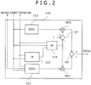
- FIG. 2 is a functional block diagram showing the details of the battery state estimation system 110.
- the battery state estimation system 110 is provided with an SOCv computing unit 111, an SOCi computing unit 112, an IR computing unit 113, and a weight computing unit 114.
- the battery state estimation system 110 outputs a state of charge SOCw corresponding to a result of estimation of a state of charge of the battery 400.
- Other computing units will be described later.
- the SOCv computing unit 111 calculates the SOC of the battery 400 using the voltage V applied across the battery 400, which has been measured by the measuring unit 200. This will hereinafter be referred to as SOCv.
- the SOCi computing unit 112 integrates the battery current I of the battery 400 measured by the measuring unit 200 to thereby calculate the SOC of the battery 400. This is hereinafter referred to as SOCi. A method of calculating the SOCv and SOCi will be explained later.
- the IR computing unit 113 multiplies the battery current I and the internal resistance R by each other. A method of determining the internal resistance R will be described later.
- the weight computing unit 114 calculates a weight W for performing weighted addition of the SOCv and the SOCi. A method of calculating W will be described later.
- the multiplier MP1 multiplies the SOCv and the weight W by each other to determine W ⁇ SOCv.
- the subtracter DF determines (1-W).
- the multiplier MP2 multiplies the SOCi and (1-W) by each other to determine (1-W) ⁇ SOCi.
- FIG. 3 is an equivalent circuit diagram of the battery 400.
- the battery 400 can be represented by a pair of an impedance Z and a capacitance component C connected in parallel, and a series connection of an internal resistance R and an open circuit voltage OCV.
- the terminal-to-terminal voltage (closed circuit voltage: CCV) of the battery 400 is represented by the following equation (2).
- Vp is a polarization voltage and equivalent to a voltage applied across the pair of the impedance Z and capacitance component C connected in parallel.
- CCV OCV + I ⁇ R + Vp
- the open circuit voltage OCV is used to determine the SOC as will be described later, but cannot be directly measured while the battery 400 is being charged and discharged.
- the SOCv computing unit 111 subtracts the IR drop and the polarization voltage Vp from the closed circuit voltage CCV in accordance with the following equation (3) to determine the open circuit voltage OCV.
- OCV CCV ⁇ IR ⁇ Vp
- the internal resistance R and the polarization voltage Vp can be stored in the storage unit 120 in advance as property information. Since the internal resistance R and the polarization voltage Vp differ according to the state of charge of the battery 400, the temperature thereof and the like, the individual values can be stored in the storage unit 120 for every combination of these.
- Property information in which the correlation between the internal resistance R and the battery temperature T is defined, is equivalent to a "resistance table" in the present embodiment.
- FIG. 4 is a diagram showing the relationship between the open circuit voltage OCV of the battery 400 and its SOC. Since this correlation is defined by the properties of the battery 400, data that defines the correlation can be stored in the storage unit 120 in advance. The data is equivalent to an "SOC table" in the present embodiment.
- the SOCv computing unit 111 calculates the open circuit voltage OCV using the above equation (3) and refers to the SOC table with the open circuit voltage as a key, thereby being able to calculate the SOCv of the battery 400.
- the SOCi computing unit 112 integrates the charging/discharging battery current I of the battery 400 to thereby determine the SOCi of the battery 400.
- Qmax is the full charge capacity of the battery 400 and can be stored in the storage unit 120 in advance.
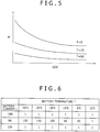
- FIG. 5 is a diagram showing the manner in which the internal resistance R of the battery 400 changes depending on the battery temperature T.
- the internal resistance R of the battery 400 is high in a low SOC state, and the value of the internal resistance R thereof is large in a low temperature state.
- SOCi is used without using SOCv susceptible to an error in the internal resistance R.
- SOCv is used without using SOCi because it is affected by a slight measurement error of a current sensor when the battery current I is small.
- the weight computing unit 114 determines a weight W in such a manner that SOCw is calculated using SOCv principally when the battery current I is small and SOCw is calculated using SOCi principally when the battery current I is large. Likewise, the weight computing unit 114 determines a weight W in such a manner that when the internal resistance R is small, SOCw is calculated using SOCv principally and when the internal resistance R is large, SOCw is calculated using SOCi principally. That is, the weight W related to SOCv is set large as the battery current I becomes smaller, and the weight W related to SOCv is set large as the internal resistance R becomes smaller.
- the weight computing unit 114 determines the weight W as described above in principle, it is necessary to correct the weight W due to the following reasons when the battery temperature T is low and the battery current I is small.
- the internal resistance R may greatly change depending on the battery current I flowing at that time.
- the present inventors of the present application have found out that there is a noticeable trend that when the battery current I is small and the battery temperature T is low, the internal resistance R extremely changes greatly and does not coincide with the pre-determined correlation between the internal resistance R and the battery temperature T.
- the weight W becomes large according to the above equation (5) when the battery current I is small, the specific gravity at SOCv is set large in principle. Since, however, the value of the internal resistance R becomes extremely inaccurate as describe above where the battery current I is small and the battery temperature T is low, SOCv susceptible to an error in the internal resistance R should not be used. Thus, in this case, the weight W is corrected in such a manner that SOCi is mainly used.
- FIG. 6 is a diagram showing a data example of the association table stored in the storage unit 120.
- the association table is a data table in which the correlation of coefficients Wgain used to correct the battery temperature T, battery current I and weight W is defined.
- the weight W since the value of Wgain is large as the battery temperature T becomes lower and the battery current I becomes smaller, the weight W becomes small. That is, when the battery temperature T is a predetermined threshold value or less and the battery current I is a predetermined threshold value or less, the weight W is multiplied by 1/Wgain corresponding to a coefficient less than 1 to reduce the weight W, thus making it possible to increase the specific gravity at SOCi.
- the properties of the battery 400 are preferably examined in advance to determine suitable threshold values.
- the battery temperature T is defined at 10°C intervals and the battery current I is defined at 10A intervals in FIG. 6
- the intervals to be defined may be defined as appropriate according to the properties of the battery 400 and the like in like manner.
- the weight W is corrected in such a manner that the specific gravity at SOCi becomes large. It is thus possible to minimize the influence of error expansion due to the internal resistance R, which is difficult to predict under conditions of the low temperature and the small current and estimate SOC with satisfactory accuracy.
- the coefficient Wgain is defined according to the association table shown in FIG. 6
- the value of Wgain corresponding to the battery temperature T or the battery current I undefined in the association table can be determined by performing interpolation operations such as linear interpolation, etc. by the weight computing unit 114.
Landscapes
- Physics & Mathematics (AREA)
- General Physics & Mathematics (AREA)
- Engineering & Computer Science (AREA)
- Power Engineering (AREA)
- Secondary Cells (AREA)
- Charge And Discharge Circuits For Batteries Or The Like (AREA)
- Tests Of Electric Status Of Batteries (AREA)
Claims (8)
- Système d'estimation d'état de batterie qui est configuré pour estimer un état de charge d'une batterie rechargeable (400), ledit système d'estimation d'état de batterie (110) comprenant :une unité de calcul SOCv (111) qui est configurée pour calculer un état de charge de la batterie (400) en utilisant un voltage appliqué aux bornes de la batterie (400) ;une unité de calcul SOCi (112) qui est configurée pour intégrer un courant qui s'écoule à travers la batterie (400) afin de calculer un état de charge de la batterie (400) ; etune unité de calcul SOCw qui est configurée pour effectuer une addition pondérée sur l'état de charge de la batterie (400) calculé par l'unité de calcul SOCv (111) et l'état de charge de la batterie (400) calculé par l'unité de calcul SOCi (112) ;une unité de mesure de température qui est configurée pour mesurer la température de la batterie (400) ;une unité de mesure de courant qui est configurée pour mesurer le courant qui s'écoule à travers la batterie (400) ;une unité de mesure de voltage qui est configurée pour mesurer le voltage appliqué aux bornes de la batterie (400) ;une unité de mesure de résistance qui est configurée pour mesurer une résistance interne de la batterie (400) ; etune unité de calcul de facteur de pondération (114) qui est configurée pour calculer un facteur de pondération utiliser lorsque l'unité de calcul SOCw effectue l'addition pondérée,dans lequel l'unité de calcul de facteur de pondération (114) est configurée pour calculer le facteur de pondération de telle manière que le facteur de pondération en relation à l'état de charge calculé par l'unité de calcul SOCv (111) devient important lorsque le courant qui s'écoule à travers la batterie (400) devient plus faible, et le facteur de pondération en relation à l'état de charge calculé par l'unité de calcul SOCv (111) devient important lorsque la résistance interne de la batterie (400) devient plus faible ;ledit système d'estimation d'état de batterie étant caractérisé par :une unité de stockage (120) qui est configurée pour stocker à l'intérieur un tableau d'association dans lequel une corrélation entre la température de la batterie (400), le courant qui s'écoule à travers la batterie (400) et un coefficient est définie,dans lequel quand la température de la batterie (400) est égale ou inférieure à une valeur seuil de température prédéterminée et que le courant qui s'écoule à travers la batterie (400) est égal ou inférieur à une valeur seuil de courant prédéterminé, l'unité de calcul de facteur de pondération (114) est configurée pour calculer le facteur de pondération en se référant au tableau d'association avec la température de la batterie (400) et le courant qui s'écoule à travers la batterie (400) à titre de paramètres, et pour multiplier avec un inverse du coefficient et ainsi diminuer le facteur de pondération en relation avec l'état de charge de la batterie (400) calculé par l'unité de calcul SOCv (111) et augmenter le facteur de pondération en relation avec l'état de charge de la batterie (400) calculé par l'unité de calcul SOCi (112), dans lequel le facteur de pondération est corrigé d'une manière telle que le facteur de pondération en relation avec l'état de charge de la batterie calculé par l'unité de calcul SOCi est principalement utilisé dans des cas dans lesquels le courant de batterie est faible et la température de la batterie est basse.
- Système d'estimation d'état de batterie selon la revendication 1, dans lequel l'unité de calcul de facteur de pondération (114) est configurée pour calculer le facteur de pondération par interpolation linéaire d'une corrélation entre la température et le facteur de pondération défini dans le tableau d'association par rapport à la température indéfinie dans le tableau d'association.
- Système d'estimation d'état de batterie selon la revendication 1 ou 2 dans lequel l'unité de calcul de facteur de pondération (114) est configurée pour calculer le facteur de pondération par interpolation linéaire d'une corrélation entre le courant et le facteur de pondération défini dans le tableau d'association par rapport au courant indéfini dans le tableau d'association.
- Système d'estimation d'état de batterie selon l'une quelconque des revendications 1 à 3, incluant un tableau de résistance dans lequel une corrélation entre la température de la batterie (400) et la résistance interne de la batterie (400) est définie,
dans lequel l'unité de mesure de résistance est configurée pour mesurer la résistance interne de la batterie (400) en se référant au tableau de résistance avec la température de la batterie (400) à titre de paramètre. - Système d'estimation d'état de batterie selon l'une quelconque des revendications 1 à 4, incluant une table SOC dans laquelle une corrélation entre un voltage en circuit ouvert de la batterie (400) et un état de charge de la batterie (400) est définie,
dans lequel l'unité de calcul SOCv (111) est configurée pour calculer l'état de charge de la batterie (400) en se référant à la table SOC avec le voltage en circuit ouvert de la batterie (400) à titre de paramètre. - Système de contrôle de batterie comprenant :un système d'estimation d'état de batterie (110) selon l'une quelconque des revendications 1 à 5,dans lequel le système de contrôle de batterie est configuré pour contrôler la batterie (400) en utilisant l'état de charge de la batterie (400) estimé par le système d'estimation d'état de batterie (110).
- Système de batterie comprenant :un système de contrôle de batterie selon la revendication 6 ; etune batterie (400) configurée pour être contrôlée par le système de contrôle de batterie.
- Procédé d'estimation d'un état de charge d'une batterie rechargeable, comprenant les étapes consistant à :effectuer une opération SOCv pour calculer un état de charge de la batterie (400) en utilisant un voltage appliqué aux bornes de la batterie (400) ;effectuer une opération SOCi pour intégrer un courant qui s'écoule à travers la batterie (400) afin de calculer un état de charge de la batterie (400) ;effectuer une opération SOCw pour effectuer une addition pondérée sur l'état de charge de la batterie (400) calculée dans l'étape d'opération SOCv et l'état de charge de la batterie (400) calculée dans l'étape d'opération SOCi ;effectuer une mesure de la température de la batterie (400) ;effectuer une mesure du courant qui s'écoule à travers la batterie (400) ;effectuer une mesure du voltage appliqué aux bornes de la batterie (400) ;effectuer une mesure d'une résistance interne de la batterie ;dans lequel le facteur de pondération est calculé d'une manière telle que le facteur de pondération en relation avec l'état de charge calculé dans l'opération SOCv devient important lorsque le courant qui s'écoule à travers la batterie devient plus faible, et le facteur de pondération en relation à l'état de charge calculé dans l'opération SOCv devient important lorsque la résistance interne de la batterie (400) devient plus faible ;ledit procédé étant caractérisé par :l'étape consistant à effectuer le stockage d'un tableau d'association dans lequel une corrélation entre la température de la batterie (400), le courant qui s'écoule à travers la batterie (400) et un coefficient est définie,dans lequel, dans l'étape de l'opération SOCw, quand la température de la batterie (400) est égale ou inférieure à une valeur seuil de température prédéterminée et que le courant qui s'écoule à travers la batterie (400) est égal ou inférieur à une valeur seuil de courant prédéterminé, le facteur de pondération est calculé en se référant au tableau d'association avec la température de la batterie (400) et le courant qui s'écoule à travers la batterie (400) à titre de paramètres et par multiplication avec un inverse du coefficient afin de diminuer ainsi le facteur de pondération en relation avec l'état de charge de la batterie (400) calculé dans l'opération SOCv et d'augmenter le facteur de pondération en relation avec l'état de charge de la batterie (400) calculée dans l'opération SOCi, et dans lequel le facteur de pondération est corrigé d'une manière telle que le facteur de pondération en relation avec état de charge de la batterie calculé dans l'opération SOCi est principalement utilisé dans des cas dans lequel le courant de batterie est faible et la température de la batterie est basse.
Applications Claiming Priority (1)
| Application Number | Priority Date | Filing Date | Title |
|---|---|---|---|
| JP2012185453A JP5863603B2 (ja) | 2012-08-24 | 2012-08-24 | 電池状態推定装置、電池制御装置、電池システム、電池状態推定方法 |
Publications (3)
| Publication Number | Publication Date |
|---|---|
| EP2700964A2 EP2700964A2 (fr) | 2014-02-26 |
| EP2700964A3 EP2700964A3 (fr) | 2015-09-09 |
| EP2700964B1 true EP2700964B1 (fr) | 2018-10-10 |
Family
ID=48900899
Family Applications (1)
| Application Number | Title | Priority Date | Filing Date |
|---|---|---|---|
| EP13179118.8A Active EP2700964B1 (fr) | 2012-08-24 | 2013-08-02 | Système et procédé d'estimation d'état de batterie, système de commande de batterie et système de batterie |
Country Status (4)
| Country | Link |
|---|---|
| US (1) | US9537325B2 (fr) |
| EP (1) | EP2700964B1 (fr) |
| JP (1) | JP5863603B2 (fr) |
| CN (1) | CN103630843B (fr) |
Families Citing this family (40)
| Publication number | Priority date | Publication date | Assignee | Title |
|---|---|---|---|---|
| US20140340045A1 (en) * | 2012-01-26 | 2014-11-20 | Calsonic Kansei Corporation | Apparatus for battery state estimation |
| JP2015155859A (ja) * | 2014-02-21 | 2015-08-27 | ソニー株式会社 | 電池残量推定装置、電池パック、蓄電装置、電動車両および電池残量推定方法 |
| EP3121613A4 (fr) * | 2014-03-18 | 2017-12-27 | Kabushiki Kaisha Toshiba | Procédé d'estimation de dégradation, système d'estimation de dégradation, et programme d'estimation de dégradation |
| EA201691950A1 (ru) * | 2014-03-28 | 2017-01-30 | Сис Рисорсез Лтд. | Системы и способы для обеспечения указания напряжения аккумуляторной батареи в электронном устройстве для курения |
| JP6279387B2 (ja) * | 2014-04-10 | 2018-02-14 | カルソニックカンセイ株式会社 | 比重推定装置および比重推定方法 |
| JP6164168B2 (ja) * | 2014-06-26 | 2017-07-19 | トヨタ自動車株式会社 | 車両用制御装置 |
| KR101717001B1 (ko) * | 2014-07-25 | 2017-03-15 | 가부시끼가이샤 도시바 | 내부 상태 추정 시스템 및 그 추정 방법 |
| JP6386351B2 (ja) * | 2014-12-02 | 2018-09-05 | 株式会社キャプテックス | 蓄電池の充電率の算出方法 |
| CN105738815B (zh) * | 2014-12-12 | 2019-10-22 | 国家电网公司 | 一种在线检测锂离子电池健康状态的方法 |
| CN104535933B (zh) * | 2014-12-26 | 2017-08-29 | 湖南金杯新能源发展有限公司 | 电池剩余电量测量方法与系统 |
| KR101776844B1 (ko) * | 2015-11-05 | 2017-09-11 | 영화테크(주) | 배터리 센서를 이용한 자동차 배터리의 건강상태 추정방법 |
| US10845417B2 (en) | 2016-01-29 | 2020-11-24 | Vehicle Energy Japan, Inc. | Battery state estimation device, battery control device, battery system, battery state estimation method |
| WO2017158727A1 (fr) * | 2016-03-15 | 2017-09-21 | 株式会社東芝 | Dispositif d'estimation de capacité de batterie, et programme |
| DE112017001422B4 (de) * | 2016-05-12 | 2019-03-21 | Hitachi Automotive Systems, Ltd. | Batteriezustands-Schätzvorrichtung |
| KR101846690B1 (ko) * | 2016-08-01 | 2018-05-18 | 현대자동차주식회사 | Wls 기반 soh 추정 시스템 및 방법 |
| WO2018050031A1 (fr) * | 2016-09-13 | 2018-03-22 | 南京德朔实业有限公司 | Système d'outil électrique et procédé de commande de système d'outil électrique |
| JP6789046B2 (ja) * | 2016-09-21 | 2020-11-25 | ローム株式会社 | リチャージャブルバッテリの残量検出回路、それを用いた電子機器、自動車ならびに充電状態の検出方法 |
| DE112017005089T5 (de) * | 2016-10-06 | 2019-08-01 | Kabushiki Kaisha Toyota Jidoshokki | Leistungsspeichervorrichtung |
| JP6661024B2 (ja) * | 2016-10-26 | 2020-03-11 | 日立オートモティブシステムズ株式会社 | 電池制御装置 |
| US10983168B2 (en) | 2016-11-18 | 2021-04-20 | Semiconductor Components Industries, Llc | Methods and apparatus for reporting a relative state of charge of a battery |
| US10184987B2 (en) * | 2016-11-18 | 2019-01-22 | Semiconductor Components Industries, Llc | Methods and apparatus for reporting a relative state of charge of a battery |
| JP6567583B2 (ja) * | 2017-03-15 | 2019-08-28 | 株式会社東芝 | 電池安全性評価装置、電池制御装置、電池安全性評価方法、プログラム、制御回路及び蓄電システム |
| EP3379278A1 (fr) * | 2017-03-20 | 2018-09-26 | ABB Schweiz AG | Accumulateur d'énergie de batterie |
| CN107167737A (zh) * | 2017-03-31 | 2017-09-15 | 惠州市蓝微新源技术有限公司 | 一种电池系统安全监控方法 |
| WO2018186088A1 (fr) * | 2017-04-07 | 2018-10-11 | 日立オートモティブシステムズ株式会社 | Dispositif de commande de batterie |
| CN107192955A (zh) * | 2017-05-12 | 2017-09-22 | 四川力垦锂动力科技有限公司 | 电动汽车用锂电池soc统计系统 |
| CN107144795A (zh) * | 2017-05-12 | 2017-09-08 | 四川力垦锂动力科技有限公司 | 一种电动汽车用锂电池剩余电量统计方法 |
| WO2019097938A1 (fr) * | 2017-11-14 | 2019-05-23 | 日立オートモティブシステムズ株式会社 | Dispositif d'estimation d'état de batterie |
| US11237218B2 (en) * | 2018-06-25 | 2022-02-01 | Google Llc | Battery state estimation |
| WO2020026509A1 (fr) * | 2018-07-30 | 2020-02-06 | 日立オートモティブシステムズ株式会社 | Dispositif d'estimation d'état de cellule et dispositif de commande de cellule |
| JP7089049B2 (ja) * | 2018-10-12 | 2022-06-21 | ビークルエナジージャパン株式会社 | 電池制御装置 |
| CN109633478B (zh) * | 2018-12-30 | 2020-11-17 | 蜂巢能源科技有限公司 | 电池容量预测系统及预测方法 |
| CN113994222B (zh) * | 2019-06-07 | 2025-06-03 | 日本汽车能源株式会社 | 电池控制装置 |
| TWI715367B (zh) * | 2019-12-23 | 2021-01-01 | 台達電子工業股份有限公司 | 電池控制器與其電池電量量測方法 |
| CN114678913A (zh) * | 2020-12-24 | 2022-06-28 | 九号智能(常州)科技有限公司 | 电动代步车的充电方法、装置及电动代步车 |
| JP7547400B2 (ja) * | 2022-01-24 | 2024-09-09 | 本田技研工業株式会社 | 蓄電システム |
| KR20250060742A (ko) * | 2023-10-26 | 2025-05-07 | 삼성에스디아이 주식회사 | 배터리 잔여 용량 산출 방법 및 시스템 |
| CN117310521B (zh) * | 2023-11-29 | 2024-02-20 | 深圳市普裕时代新能源科技有限公司 | 锂离子电池的充电状态校准方法、系统、设备及存储介质 |
| WO2026083615A1 (fr) * | 2024-10-15 | 2026-04-23 | ビークルエナジージャパン株式会社 | Dispositif d'estimation de l'état de charge d'une batterie secondaire, dispositif de commande de batterie secondaire et dispositif de commande d'alimentation électrique d'un véhicule électrique |
| CN120802103B (zh) * | 2025-09-10 | 2025-12-26 | 山西鸿瑞建设股份有限公司 | 一种基于bms的储能电源安全预测与保养方法及系统 |
Family Cites Families (22)
| Publication number | Priority date | Publication date | Assignee | Title |
|---|---|---|---|---|
| JP2003035755A (ja) * | 2001-07-25 | 2003-02-07 | Hitachi Ltd | 電池蓄電量検出方法 |
| DE10153916A1 (de) * | 2001-11-02 | 2003-05-15 | Nbt Gmbh | Verfahren zur Bestimmung des Ladezustandes von Akkumulatoren durch Integration der bei Ladung und Entladung fließenden Strommengen |
| US6845332B2 (en) * | 2001-11-16 | 2005-01-18 | Toyota Jidosha Kabushiki Kaisha | State of charge calculation device and state of charge calculation method |
| JP3778060B2 (ja) * | 2001-11-16 | 2006-05-24 | トヨタ自動車株式会社 | 電池残存容量算出方法 |
| JP4157317B2 (ja) * | 2002-04-10 | 2008-10-01 | 株式会社日立製作所 | 状態検知装置及びこれを用いた各種装置 |
| DE10252760B4 (de) * | 2002-11-13 | 2009-07-02 | Vb Autobatterie Gmbh & Co. Kgaa | Verfahren zur Vorhersage des Innenwiderstands einer Speicherbatterie und Überwachungseinrichtung für Speicherbatterien |
| DE10335928B4 (de) * | 2003-08-06 | 2006-11-09 | Vb Autobatterie Gmbh | Verfahren zur Ermittlung einer von der Elektrolytkonzentration und/oder Elektrolytverteilung abhängigen auf den Ladezustand einer Speicherbatterie bezogenen Kenngröße |
| JP4075762B2 (ja) * | 2003-10-10 | 2008-04-16 | トヨタ自動車株式会社 | 二次電池における残存容量の算出装置および算出方法 |
| JP4583765B2 (ja) * | 2004-01-14 | 2010-11-17 | 富士重工業株式会社 | 蓄電デバイスの残存容量演算装置 |
| JP4570918B2 (ja) * | 2004-07-22 | 2010-10-27 | 富士重工業株式会社 | 蓄電デバイスの残存容量演算装置 |
| JP2006112786A (ja) * | 2004-10-12 | 2006-04-27 | Sanyo Electric Co Ltd | 電池の残容量検出方法及び電源装置 |
| JP4767558B2 (ja) * | 2005-03-07 | 2011-09-07 | 日立ビークルエナジー株式会社 | 電源装置用状態検知装置,電源装置及び電源装置に用いられる初期特性抽出装置 |
| US7498772B2 (en) * | 2006-04-06 | 2009-03-03 | International Truck Intellectual Property Company, Llc | Method and system of modeling energy flow for vehicle battery diagnostic monitoring |
| US7652448B2 (en) * | 2007-04-12 | 2010-01-26 | International Truck Intellectual Property Company, Llc | Vehicle battery state of charge indicator |
| JP4995643B2 (ja) * | 2007-06-11 | 2012-08-08 | パナソニック株式会社 | 非水系電解質二次電池の内部短絡検知方法および装置 |
| KR100970841B1 (ko) * | 2008-08-08 | 2010-07-16 | 주식회사 엘지화학 | 배터리 전압 거동을 이용한 배터리 용량 퇴화 추정 장치 및방법 |
| FR2943794B1 (fr) * | 2009-03-24 | 2011-05-06 | Saft Groupe Sa | Procede de determination de l'etat de sante d'une batterie |
| JP5439126B2 (ja) * | 2009-03-31 | 2014-03-12 | 株式会社日立製作所 | 電源装置用状態検知装置 |
| JP5646214B2 (ja) * | 2010-05-27 | 2014-12-24 | 三洋電機株式会社 | 電源装置 |
| WO2011161781A1 (fr) * | 2010-06-23 | 2011-12-29 | トヨタ自動車株式会社 | Dispositif de commande pour véhicule et procédé de commande pour véhicule |
| JP5287844B2 (ja) * | 2010-12-27 | 2013-09-11 | 株式会社デンソー | 二次電池の残存容量演算装置 |
| CN103635822B (zh) * | 2011-08-30 | 2016-02-10 | 三洋电机株式会社 | 电池系统、电动车辆、移动体、电力储存装置以及电源装置 |
-
2012
- 2012-08-24 JP JP2012185453A patent/JP5863603B2/ja active Active
-
2013
- 2013-08-02 EP EP13179118.8A patent/EP2700964B1/fr active Active
- 2013-08-09 CN CN201310347196.7A patent/CN103630843B/zh active Active
- 2013-08-19 US US13/970,128 patent/US9537325B2/en active Active
Non-Patent Citations (1)
| Title |
|---|
| None * |
Also Published As
| Publication number | Publication date |
|---|---|
| JP2014044074A (ja) | 2014-03-13 |
| EP2700964A3 (fr) | 2015-09-09 |
| CN103630843A (zh) | 2014-03-12 |
| US9537325B2 (en) | 2017-01-03 |
| EP2700964A2 (fr) | 2014-02-26 |
| US20140055100A1 (en) | 2014-02-27 |
| JP5863603B2 (ja) | 2016-02-16 |
| CN103630843B (zh) | 2016-12-07 |
Similar Documents
| Publication | Publication Date | Title |
|---|---|---|
| EP2700964B1 (fr) | Système et procédé d'estimation d'état de batterie, système de commande de batterie et système de batterie | |
| EP3410137B1 (fr) | Dispositif d'estimation d'état de cellule, dispositif de commande de cellule, système de cellule et procédé d'estimation d'état de cellule | |
| JP5058814B2 (ja) | バッテリーの状態及びパラメーターの推定システム及び方法 | |
| JP6734784B2 (ja) | バッテリの健全性を推定する方法 | |
| JP5287844B2 (ja) | 二次電池の残存容量演算装置 | |
| EP1701175B1 (fr) | Alimentation électrique avec détecteur de l'état et moyens de détermination des caractéristiques initiales | |
| US9759779B2 (en) | State of charge estimation device and method of estimating state of charge | |
| EP2321663B1 (fr) | Appareil et procédé pour estimer l'état de santé d'une batterie en fonction d'un motif de variation de tension de batterie | |
| KR102572652B1 (ko) | 배터리의 충전상태를 추정하는 방법 | |
| JP6509725B2 (ja) | バッテリの充電状態の推定 | |
| CN112912747B (zh) | 电池状态推算装置和电池控制装置 | |
| JP2020060581A (ja) | 蓄電素子管理装置、socのリセット方法、蓄電素子モジュール、蓄電素子管理プログラム及び移動体 | |
| JP5292375B2 (ja) | バッテリの充電率推定装置 | |
| CN108369258A (zh) | 状态估计装置、状态估计方法 | |
| EP2102672A1 (fr) | Système de gestion de batterie | |
| KR20170116427A (ko) | 배터리 상태 추정 장치 및 방법 | |
| KR20170092589A (ko) | 배터리의 셀의 충전의 상태를 추정하는 자동적 방법 | |
| JP2014025738A (ja) | 残容量推定装置 | |
| EP3605123B1 (fr) | Dispositif de commande et procédé de commande de batterie rechargeable | |
| JP5832380B2 (ja) | 組電池のセルの状態推定装置 | |
| WO2018186088A1 (fr) | Dispositif de commande de batterie | |
| JP6895537B2 (ja) | 電池状態推定装置 |
Legal Events
| Date | Code | Title | Description |
|---|---|---|---|
| PUAI | Public reference made under article 153(3) epc to a published international application that has entered the european phase |
Free format text: ORIGINAL CODE: 0009012 |
|
| 17P | Request for examination filed |
Effective date: 20131004 |
|
| AK | Designated contracting states |
Kind code of ref document: A2 Designated state(s): AL AT BE BG CH CY CZ DE DK EE ES FI FR GB GR HR HU IE IS IT LI LT LU LV MC MK MT NL NO PL PT RO RS SE SI SK SM TR |
|
| AX | Request for extension of the european patent |
Extension state: BA ME |
|
| RAP1 | Party data changed (applicant data changed or rights of an application transferred) |
Owner name: HITACHI AUTOMOTIVE SYSTEMS, LTD. |
|
| PUAL | Search report despatched |
Free format text: ORIGINAL CODE: 0009013 |
|
| AK | Designated contracting states |
Kind code of ref document: A3 Designated state(s): AL AT BE BG CH CY CZ DE DK EE ES FI FR GB GR HR HU IE IS IT LI LT LU LV MC MK MT NL NO PL PT RO RS SE SI SK SM TR |
|
| AX | Request for extension of the european patent |
Extension state: BA ME |
|
| RIC1 | Information provided on ipc code assigned before grant |
Ipc: G01R 31/36 20060101AFI20150804BHEP |
|
| 17Q | First examination report despatched |
Effective date: 20160831 |
|
| STAA | Information on the status of an ep patent application or granted ep patent |
Free format text: STATUS: EXAMINATION IS IN PROGRESS |
|
| GRAP | Despatch of communication of intention to grant a patent |
Free format text: ORIGINAL CODE: EPIDOSNIGR1 |
|
| STAA | Information on the status of an ep patent application or granted ep patent |
Free format text: STATUS: GRANT OF PATENT IS INTENDED |
|
| INTG | Intention to grant announced |
Effective date: 20180226 |
|
| GRAS | Grant fee paid |
Free format text: ORIGINAL CODE: EPIDOSNIGR3 |
|
| GRAA | (expected) grant |
Free format text: ORIGINAL CODE: 0009210 |
|
| STAA | Information on the status of an ep patent application or granted ep patent |
Free format text: STATUS: THE PATENT HAS BEEN GRANTED |
|
| AK | Designated contracting states |
Kind code of ref document: B1 Designated state(s): AL AT BE BG CH CY CZ DE DK EE ES FI FR GB GR HR HU IE IS IT LI LT LU LV MC MK MT NL NO PL PT RO RS SE SI SK SM TR |
|
| REG | Reference to a national code |
Ref country code: GB Ref legal event code: FG4D |
|
| REG | Reference to a national code |
Ref country code: CH Ref legal event code: EP Ref country code: AT Ref legal event code: REF Ref document number: 1051881 Country of ref document: AT Kind code of ref document: T Effective date: 20181015 |
|
| REG | Reference to a national code |
Ref country code: IE Ref legal event code: FG4D |
|
| REG | Reference to a national code |
Ref country code: DE Ref legal event code: R096 Ref document number: 602013044760 Country of ref document: DE |
|
| REG | Reference to a national code |
Ref country code: NL Ref legal event code: MP Effective date: 20181010 |
|
| REG | Reference to a national code |
Ref country code: LT Ref legal event code: MG4D |
|
| REG | Reference to a national code |
Ref country code: AT Ref legal event code: MK05 Ref document number: 1051881 Country of ref document: AT Kind code of ref document: T Effective date: 20181010 |
|
| PG25 | Lapsed in a contracting state [announced via postgrant information from national office to epo] |
Ref country code: NL Free format text: LAPSE BECAUSE OF FAILURE TO SUBMIT A TRANSLATION OF THE DESCRIPTION OR TO PAY THE FEE WITHIN THE PRESCRIBED TIME-LIMIT Effective date: 20181010 |
|
| PG25 | Lapsed in a contracting state [announced via postgrant information from national office to epo] |
Ref country code: IS Free format text: LAPSE BECAUSE OF FAILURE TO SUBMIT A TRANSLATION OF THE DESCRIPTION OR TO PAY THE FEE WITHIN THE PRESCRIBED TIME-LIMIT Effective date: 20190210 Ref country code: FI Free format text: LAPSE BECAUSE OF FAILURE TO SUBMIT A TRANSLATION OF THE DESCRIPTION OR TO PAY THE FEE WITHIN THE PRESCRIBED TIME-LIMIT Effective date: 20181010 Ref country code: NO Free format text: LAPSE BECAUSE OF FAILURE TO SUBMIT A TRANSLATION OF THE DESCRIPTION OR TO PAY THE FEE WITHIN THE PRESCRIBED TIME-LIMIT Effective date: 20190110 Ref country code: AT Free format text: LAPSE BECAUSE OF FAILURE TO SUBMIT A TRANSLATION OF THE DESCRIPTION OR TO PAY THE FEE WITHIN THE PRESCRIBED TIME-LIMIT Effective date: 20181010 Ref country code: LV Free format text: LAPSE BECAUSE OF FAILURE TO SUBMIT A TRANSLATION OF THE DESCRIPTION OR TO PAY THE FEE WITHIN THE PRESCRIBED TIME-LIMIT Effective date: 20181010 Ref country code: LT Free format text: LAPSE BECAUSE OF FAILURE TO SUBMIT A TRANSLATION OF THE DESCRIPTION OR TO PAY THE FEE WITHIN THE PRESCRIBED TIME-LIMIT Effective date: 20181010 Ref country code: PL Free format text: LAPSE BECAUSE OF FAILURE TO SUBMIT A TRANSLATION OF THE DESCRIPTION OR TO PAY THE FEE WITHIN THE PRESCRIBED TIME-LIMIT Effective date: 20181010 Ref country code: HR Free format text: LAPSE BECAUSE OF FAILURE TO SUBMIT A TRANSLATION OF THE DESCRIPTION OR TO PAY THE FEE WITHIN THE PRESCRIBED TIME-LIMIT Effective date: 20181010 Ref country code: ES Free format text: LAPSE BECAUSE OF FAILURE TO SUBMIT A TRANSLATION OF THE DESCRIPTION OR TO PAY THE FEE WITHIN THE PRESCRIBED TIME-LIMIT Effective date: 20181010 Ref country code: BG Free format text: LAPSE BECAUSE OF FAILURE TO SUBMIT A TRANSLATION OF THE DESCRIPTION OR TO PAY THE FEE WITHIN THE PRESCRIBED TIME-LIMIT Effective date: 20190110 |
|
| PG25 | Lapsed in a contracting state [announced via postgrant information from national office to epo] |
Ref country code: PT Free format text: LAPSE BECAUSE OF FAILURE TO SUBMIT A TRANSLATION OF THE DESCRIPTION OR TO PAY THE FEE WITHIN THE PRESCRIBED TIME-LIMIT Effective date: 20190210 Ref country code: AL Free format text: LAPSE BECAUSE OF FAILURE TO SUBMIT A TRANSLATION OF THE DESCRIPTION OR TO PAY THE FEE WITHIN THE PRESCRIBED TIME-LIMIT Effective date: 20181010 Ref country code: GR Free format text: LAPSE BECAUSE OF FAILURE TO SUBMIT A TRANSLATION OF THE DESCRIPTION OR TO PAY THE FEE WITHIN THE PRESCRIBED TIME-LIMIT Effective date: 20190111 Ref country code: SE Free format text: LAPSE BECAUSE OF FAILURE TO SUBMIT A TRANSLATION OF THE DESCRIPTION OR TO PAY THE FEE WITHIN THE PRESCRIBED TIME-LIMIT Effective date: 20181010 Ref country code: RS Free format text: LAPSE BECAUSE OF FAILURE TO SUBMIT A TRANSLATION OF THE DESCRIPTION OR TO PAY THE FEE WITHIN THE PRESCRIBED TIME-LIMIT Effective date: 20181010 |
|
| REG | Reference to a national code |
Ref country code: DE Ref legal event code: R097 Ref document number: 602013044760 Country of ref document: DE |
|
| PG25 | Lapsed in a contracting state [announced via postgrant information from national office to epo] |
Ref country code: IT Free format text: LAPSE BECAUSE OF FAILURE TO SUBMIT A TRANSLATION OF THE DESCRIPTION OR TO PAY THE FEE WITHIN THE PRESCRIBED TIME-LIMIT Effective date: 20181010 Ref country code: CZ Free format text: LAPSE BECAUSE OF FAILURE TO SUBMIT A TRANSLATION OF THE DESCRIPTION OR TO PAY THE FEE WITHIN THE PRESCRIBED TIME-LIMIT Effective date: 20181010 Ref country code: DK Free format text: LAPSE BECAUSE OF FAILURE TO SUBMIT A TRANSLATION OF THE DESCRIPTION OR TO PAY THE FEE WITHIN THE PRESCRIBED TIME-LIMIT Effective date: 20181010 |
|
| PLBE | No opposition filed within time limit |
Free format text: ORIGINAL CODE: 0009261 |
|
| STAA | Information on the status of an ep patent application or granted ep patent |
Free format text: STATUS: NO OPPOSITION FILED WITHIN TIME LIMIT |
|
| PG25 | Lapsed in a contracting state [announced via postgrant information from national office to epo] |
Ref country code: EE Free format text: LAPSE BECAUSE OF FAILURE TO SUBMIT A TRANSLATION OF THE DESCRIPTION OR TO PAY THE FEE WITHIN THE PRESCRIBED TIME-LIMIT Effective date: 20181010 Ref country code: SM Free format text: LAPSE BECAUSE OF FAILURE TO SUBMIT A TRANSLATION OF THE DESCRIPTION OR TO PAY THE FEE WITHIN THE PRESCRIBED TIME-LIMIT Effective date: 20181010 Ref country code: SK Free format text: LAPSE BECAUSE OF FAILURE TO SUBMIT A TRANSLATION OF THE DESCRIPTION OR TO PAY THE FEE WITHIN THE PRESCRIBED TIME-LIMIT Effective date: 20181010 Ref country code: RO Free format text: LAPSE BECAUSE OF FAILURE TO SUBMIT A TRANSLATION OF THE DESCRIPTION OR TO PAY THE FEE WITHIN THE PRESCRIBED TIME-LIMIT Effective date: 20181010 |
|
| 26N | No opposition filed |
Effective date: 20190711 |
|
| PG25 | Lapsed in a contracting state [announced via postgrant information from national office to epo] |
Ref country code: SI Free format text: LAPSE BECAUSE OF FAILURE TO SUBMIT A TRANSLATION OF THE DESCRIPTION OR TO PAY THE FEE WITHIN THE PRESCRIBED TIME-LIMIT Effective date: 20181010 |
|
| REG | Reference to a national code |
Ref country code: DE Ref legal event code: R082 Ref document number: 602013044760 Country of ref document: DE Representative=s name: MERH-IP MATIAS ERNY REICHL HOFFMANN PATENTANWA, DE Ref country code: DE Ref legal event code: R081 Ref document number: 602013044760 Country of ref document: DE Owner name: VEHICLE ENERGY JAPAN INC., HITACHINAKA-SHI, JP Free format text: FORMER OWNER: HITACHI AUTOMOTIVE SYSTEMS, LTD., HITACHINAKA-SHI, IBARAKI, JP |
|
| PG25 | Lapsed in a contracting state [announced via postgrant information from national office to epo] |
Ref country code: TR Free format text: LAPSE BECAUSE OF FAILURE TO SUBMIT A TRANSLATION OF THE DESCRIPTION OR TO PAY THE FEE WITHIN THE PRESCRIBED TIME-LIMIT Effective date: 20181010 |
|
| GBPC | Gb: european patent ceased through non-payment of renewal fee |
Effective date: 20190802 |
|
| PG25 | Lapsed in a contracting state [announced via postgrant information from national office to epo] |
Ref country code: LU Free format text: LAPSE BECAUSE OF NON-PAYMENT OF DUE FEES Effective date: 20190802 Ref country code: CH Free format text: LAPSE BECAUSE OF NON-PAYMENT OF DUE FEES Effective date: 20190831 Ref country code: LI Free format text: LAPSE BECAUSE OF NON-PAYMENT OF DUE FEES Effective date: 20190831 Ref country code: MC Free format text: LAPSE BECAUSE OF FAILURE TO SUBMIT A TRANSLATION OF THE DESCRIPTION OR TO PAY THE FEE WITHIN THE PRESCRIBED TIME-LIMIT Effective date: 20181010 |
|
| REG | Reference to a national code |
Ref country code: BE Ref legal event code: MM Effective date: 20190831 |
|
| PG25 | Lapsed in a contracting state [announced via postgrant information from national office to epo] |
Ref country code: IE Free format text: LAPSE BECAUSE OF NON-PAYMENT OF DUE FEES Effective date: 20190802 |
|
| PG25 | Lapsed in a contracting state [announced via postgrant information from national office to epo] |
Ref country code: GB Free format text: LAPSE BECAUSE OF NON-PAYMENT OF DUE FEES Effective date: 20190802 Ref country code: BE Free format text: LAPSE BECAUSE OF NON-PAYMENT OF DUE FEES Effective date: 20190831 |
|
| PG25 | Lapsed in a contracting state [announced via postgrant information from national office to epo] |
Ref country code: CY Free format text: LAPSE BECAUSE OF FAILURE TO SUBMIT A TRANSLATION OF THE DESCRIPTION OR TO PAY THE FEE WITHIN THE PRESCRIBED TIME-LIMIT Effective date: 20181010 |
|
| PG25 | Lapsed in a contracting state [announced via postgrant information from national office to epo] |
Ref country code: HU Free format text: LAPSE BECAUSE OF FAILURE TO SUBMIT A TRANSLATION OF THE DESCRIPTION OR TO PAY THE FEE WITHIN THE PRESCRIBED TIME-LIMIT; INVALID AB INITIO Effective date: 20130802 Ref country code: MT Free format text: LAPSE BECAUSE OF FAILURE TO SUBMIT A TRANSLATION OF THE DESCRIPTION OR TO PAY THE FEE WITHIN THE PRESCRIBED TIME-LIMIT Effective date: 20181010 |
|
| PG25 | Lapsed in a contracting state [announced via postgrant information from national office to epo] |
Ref country code: MK Free format text: LAPSE BECAUSE OF FAILURE TO SUBMIT A TRANSLATION OF THE DESCRIPTION OR TO PAY THE FEE WITHIN THE PRESCRIBED TIME-LIMIT Effective date: 20181010 |
|
| PGFP | Annual fee paid to national office [announced via postgrant information from national office to epo] |
Ref country code: DE Payment date: 20250702 Year of fee payment: 13 |
|
| PGFP | Annual fee paid to national office [announced via postgrant information from national office to epo] |
Ref country code: FR Payment date: 20250703 Year of fee payment: 13 |