WO2020026509A1 - Dispositif d'estimation d'état de cellule et dispositif de commande de cellule - Google Patents
Dispositif d'estimation d'état de cellule et dispositif de commande de cellule Download PDFInfo
- Publication number
- WO2020026509A1 WO2020026509A1 PCT/JP2019/011056 JP2019011056W WO2020026509A1 WO 2020026509 A1 WO2020026509 A1 WO 2020026509A1 JP 2019011056 W JP2019011056 W JP 2019011056W WO 2020026509 A1 WO2020026509 A1 WO 2020026509A1
- Authority
- WO
- WIPO (PCT)
- Prior art keywords
- cell
- battery
- soc
- value
- battery state
- Prior art date
- Legal status (The legal status is an assumption and is not a legal conclusion. Google has not performed a legal analysis and makes no representation as to the accuracy of the status listed.)
- Ceased
Links
Images






Classifications
-
- G—PHYSICS
- G01—MEASURING; TESTING
- G01R—MEASURING ELECTRIC VARIABLES; MEASURING MAGNETIC VARIABLES
- G01R31/00—Arrangements for testing electric properties; Arrangements for locating electric faults; Arrangements for electrical testing characterised by what is being tested not provided for elsewhere
- G01R31/36—Arrangements for testing, measuring or monitoring the electrical condition of accumulators or electric batteries, e.g. capacity or state of charge [SoC]
- G01R31/382—Arrangements for monitoring battery or accumulator variables, e.g. SoC
- G01R31/3842—Arrangements for monitoring battery or accumulator variables, e.g. SoC combining voltage and current measurements
-
- G—PHYSICS
- G01—MEASURING; TESTING
- G01R—MEASURING ELECTRIC VARIABLES; MEASURING MAGNETIC VARIABLES
- G01R31/00—Arrangements for testing electric properties; Arrangements for locating electric faults; Arrangements for electrical testing characterised by what is being tested not provided for elsewhere
- G01R31/36—Arrangements for testing, measuring or monitoring the electrical condition of accumulators or electric batteries, e.g. capacity or state of charge [SoC]
- G01R31/367—Software therefor, e.g. for battery testing using modelling or look-up tables
-
- G—PHYSICS
- G01—MEASURING; TESTING
- G01R—MEASURING ELECTRIC VARIABLES; MEASURING MAGNETIC VARIABLES
- G01R31/00—Arrangements for testing electric properties; Arrangements for locating electric faults; Arrangements for electrical testing characterised by what is being tested not provided for elsewhere
- G01R31/36—Arrangements for testing, measuring or monitoring the electrical condition of accumulators or electric batteries, e.g. capacity or state of charge [SoC]
- G01R31/385—Arrangements for measuring battery or accumulator variables
- G01R31/387—Determining ampere-hour charge capacity or SoC
- G01R31/388—Determining ampere-hour charge capacity or SoC involving voltage measurements
-
- G—PHYSICS
- G01—MEASURING; TESTING
- G01R—MEASURING ELECTRIC VARIABLES; MEASURING MAGNETIC VARIABLES
- G01R31/00—Arrangements for testing electric properties; Arrangements for locating electric faults; Arrangements for electrical testing characterised by what is being tested not provided for elsewhere
- G01R31/36—Arrangements for testing, measuring or monitoring the electrical condition of accumulators or electric batteries, e.g. capacity or state of charge [SoC]
- G01R31/396—Acquisition or processing of data for testing or for monitoring individual cells or groups of cells within a battery
-
- H—ELECTRICITY
- H01—ELECTRIC ELEMENTS
- H01M—PROCESSES OR MEANS, e.g. BATTERIES, FOR THE DIRECT CONVERSION OF CHEMICAL ENERGY INTO ELECTRICAL ENERGY
- H01M10/00—Secondary cells; Manufacture thereof
- H01M10/42—Methods or arrangements for servicing or maintenance of secondary cells or secondary half-cells
- H01M10/425—Structural combination with electronic components, e.g. electronic circuits integrated to the outside of the casing
-
- H—ELECTRICITY
- H01—ELECTRIC ELEMENTS
- H01M—PROCESSES OR MEANS, e.g. BATTERIES, FOR THE DIRECT CONVERSION OF CHEMICAL ENERGY INTO ELECTRICAL ENERGY
- H01M10/00—Secondary cells; Manufacture thereof
- H01M10/42—Methods or arrangements for servicing or maintenance of secondary cells or secondary half-cells
- H01M10/44—Methods for charging or discharging
-
- H—ELECTRICITY
- H01—ELECTRIC ELEMENTS
- H01M—PROCESSES OR MEANS, e.g. BATTERIES, FOR THE DIRECT CONVERSION OF CHEMICAL ENERGY INTO ELECTRICAL ENERGY
- H01M10/00—Secondary cells; Manufacture thereof
- H01M10/42—Methods or arrangements for servicing or maintenance of secondary cells or secondary half-cells
- H01M10/48—Accumulators combined with arrangements for measuring, testing or indicating the condition of cells, e.g. the level or density of the electrolyte
-
- H—ELECTRICITY
- H02—GENERATION; CONVERSION OR DISTRIBUTION OF ELECTRIC POWER
- H02J—ELECTRIC POWER NETWORKS; CIRCUIT ARRANGEMENTS OR SYSTEMS FOR SUPPLYING OR DISTRIBUTING ELECTRIC POWER; SYSTEMS FOR STORING ELECTRIC ENERGY
- H02J7/00—Circuit arrangements for charging or discharging batteries or for supplying loads from batteries
- H02J7/80—Circuit arrangements for charging or discharging batteries or for supplying loads from batteries including monitoring or indicating arrangements
- H02J7/82—Control of state of charge [SOC]
-
- H—ELECTRICITY
- H02—GENERATION; CONVERSION OR DISTRIBUTION OF ELECTRIC POWER
- H02J—ELECTRIC POWER NETWORKS; CIRCUIT ARRANGEMENTS OR SYSTEMS FOR SUPPLYING OR DISTRIBUTING ELECTRIC POWER; SYSTEMS FOR STORING ELECTRIC ENERGY
- H02J7/00—Circuit arrangements for charging or discharging batteries or for supplying loads from batteries
- H02J7/80—Circuit arrangements for charging or discharging batteries or for supplying loads from batteries including monitoring or indicating arrangements
- H02J7/82—Control of state of charge [SOC]
- H02J7/825—Detection of fully charged condition
-
- H—ELECTRICITY
- H01—ELECTRIC ELEMENTS
- H01M—PROCESSES OR MEANS, e.g. BATTERIES, FOR THE DIRECT CONVERSION OF CHEMICAL ENERGY INTO ELECTRICAL ENERGY
- H01M10/00—Secondary cells; Manufacture thereof
- H01M10/42—Methods or arrangements for servicing or maintenance of secondary cells or secondary half-cells
- H01M10/425—Structural combination with electronic components, e.g. electronic circuits integrated to the outside of the casing
- H01M2010/4271—Battery management systems including electronic circuits, e.g. control of current or voltage to keep battery in healthy state, cell balancing
-
- H—ELECTRICITY
- H01—ELECTRIC ELEMENTS
- H01M—PROCESSES OR MEANS, e.g. BATTERIES, FOR THE DIRECT CONVERSION OF CHEMICAL ENERGY INTO ELECTRICAL ENERGY
- H01M10/00—Secondary cells; Manufacture thereof
- H01M10/42—Methods or arrangements for servicing or maintenance of secondary cells or secondary half-cells
- H01M10/425—Structural combination with electronic components, e.g. electronic circuits integrated to the outside of the casing
- H01M2010/4278—Systems for data transfer from batteries, e.g. transfer of battery parameters to a controller, data transferred between battery controller and main controller
-
- H—ELECTRICITY
- H02—GENERATION; CONVERSION OR DISTRIBUTION OF ELECTRIC POWER
- H02J—ELECTRIC POWER NETWORKS; CIRCUIT ARRANGEMENTS OR SYSTEMS FOR SUPPLYING OR DISTRIBUTING ELECTRIC POWER; SYSTEMS FOR STORING ELECTRIC ENERGY
- H02J2105/00—Networks for supplying or distributing electric power characterised by their spatial reach or by the load
- H02J2105/30—Networks for supplying or distributing electric power characterised by their spatial reach or by the load the load networks being external to vehicles, i.e. exchanging power with vehicles
- H02J2105/33—Networks for supplying or distributing electric power characterised by their spatial reach or by the load the load networks being external to vehicles, i.e. exchanging power with vehicles exchanging power with road vehicles
- H02J2105/37—Networks for supplying or distributing electric power characterised by their spatial reach or by the load the load networks being external to vehicles, i.e. exchanging power with vehicles exchanging power with road vehicles exchanging power with electric vehicles [EV] or with hybrid electric vehicles [HEV]
-
- H—ELECTRICITY
- H02—GENERATION; CONVERSION OR DISTRIBUTION OF ELECTRIC POWER
- H02J—ELECTRIC POWER NETWORKS; CIRCUIT ARRANGEMENTS OR SYSTEMS FOR SUPPLYING OR DISTRIBUTING ELECTRIC POWER; SYSTEMS FOR STORING ELECTRIC ENERGY
- H02J7/00—Circuit arrangements for charging or discharging batteries or for supplying loads from batteries
- H02J7/50—Circuit arrangements for charging or discharging batteries or for supplying loads from batteries acting upon multiple batteries simultaneously or sequentially
- H02J7/52—Circuit arrangements for charging or discharging batteries or for supplying loads from batteries acting upon multiple batteries simultaneously or sequentially for charge balancing, e.g. equalisation of charge between batteries
-
- Y—GENERAL TAGGING OF NEW TECHNOLOGICAL DEVELOPMENTS; GENERAL TAGGING OF CROSS-SECTIONAL TECHNOLOGIES SPANNING OVER SEVERAL SECTIONS OF THE IPC; TECHNICAL SUBJECTS COVERED BY FORMER USPC CROSS-REFERENCE ART COLLECTIONS [XRACs] AND DIGESTS
- Y02—TECHNOLOGIES OR APPLICATIONS FOR MITIGATION OR ADAPTATION AGAINST CLIMATE CHANGE
- Y02E—REDUCTION OF GREENHOUSE GAS [GHG] EMISSIONS, RELATED TO ENERGY GENERATION, TRANSMISSION OR DISTRIBUTION
- Y02E60/00—Enabling technologies; Technologies with a potential or indirect contribution to GHG emissions mitigation
- Y02E60/10—Energy storage using batteries
-
- Y—GENERAL TAGGING OF NEW TECHNOLOGICAL DEVELOPMENTS; GENERAL TAGGING OF CROSS-SECTIONAL TECHNOLOGIES SPANNING OVER SEVERAL SECTIONS OF THE IPC; TECHNICAL SUBJECTS COVERED BY FORMER USPC CROSS-REFERENCE ART COLLECTIONS [XRACs] AND DIGESTS
- Y02—TECHNOLOGIES OR APPLICATIONS FOR MITIGATION OR ADAPTATION AGAINST CLIMATE CHANGE
- Y02T—CLIMATE CHANGE MITIGATION TECHNOLOGIES RELATED TO TRANSPORTATION
- Y02T10/00—Road transport of goods or passengers
- Y02T10/60—Other road transportation technologies with climate change mitigation effect
- Y02T10/70—Energy storage systems for electromobility, e.g. batteries
Definitions
- the present invention relates to a battery state estimation device and a battery control device.
- a state detection device that detects the state of the power storage unit is used.
- the state of the power storage means indicates a state of charge (SOC: State $ of Charge) indicating how much charge has been made or how much charge that can be discharged remains, and a degree of deterioration.
- SOH State of Health
- the SOC of a battery system for a portable device, an electric vehicle, or the like is obtained by integrating a discharge current from a full charge, and a charge amount (remaining capacity) remaining in the power storage means with respect to a maximum chargeable charge amount (full capacity). Can be detected by calculating the ratio of In addition, the relationship between the voltage across the battery (open circuit voltage) and the remaining capacity of the battery is defined in advance in a data table or the like, and the SOC can be detected by calculating the current remaining capacity with reference to this. it can. Furthermore, SOC can be obtained by combining these methods.
- Patent Literature 1 discloses an apparatus for balancing a plurality of cells included in a battery pack.
- the apparatus measures the voltage of each cell, and respectively measures the voltage change behavior including the current cell voltage and the past cell voltage.
- Open-circuit voltage estimating means for estimating the open-circuit voltage of the cell
- SOC estimating means for estimating the SOC of each cell from the open-circuit voltage, and selecting a cell requiring balancing by comparing the estimated SOC of each cell
- a cell balancing device using a voltage change behavior of a battery cell comprising: cell balancing means for controlling a balancing circuit corresponding to a selected cell to balance the SOC of the cell.
- An object of the present invention is to provide a battery state estimating device capable of estimating the state of charge of a battery at low cost and with high accuracy in order to solve the above-mentioned problems in the prior art.
- the battery state estimating device is a device that is connected to an assembled battery in which a plurality of cells are connected in series, and estimates a state of charge of the target cell using any one of the plurality of cells as a target cell.
- a cell voltage acquisition unit that acquires a measurement result of a closed circuit voltage of a cell, a reference cell is set for the plurality of cells, a closed circuit voltage and an open circuit voltage of the reference cell, and a state of charge of the reference cell.
- a reference cell information acquisition unit for acquiring a reference SOC value to be represented, a closed circuit voltage of the target cell, and a provisional charge state of the target cell based on the closed circuit voltage and the open circuit voltage of the reference cell.
- a tentative SOC calculation unit for obtaining a tentative SOC value and an SOC calculation unit for obtaining an SOC value representing a state of charge of the target cell using a result obtained by smoothing a difference between the tentative SOC value and the reference SOC value.
- a battery control device includes a battery state estimation device, and a balancing control device that controls balancing of the battery pack based on the SOC value of each cell obtained by the battery state estimation device.
- the present invention it is possible to provide a battery state estimating device capable of estimating the state of charge of a battery at low cost and with high accuracy.
- FIG. 1 is a block diagram illustrating a configuration of a battery system according to an embodiment of the present invention. It is a block diagram which shows the detail of a measurement part and an assembled battery.
- FIG. 2 is a functional block diagram illustrating details of a battery state estimation device according to the first embodiment of the present invention. It is a figure showing the processing flow of the battery state estimation device concerning a 1st embodiment of the present invention.
- FIG. 4 is a diagram illustrating a relationship between OCV and SOC. It is a functional block diagram showing details of a battery state estimating device concerning a 2nd embodiment of the present invention. It is a figure showing the processing flow of the battery state estimation device concerning a 2nd embodiment of the present invention.
- FIG. 14 is a functional block diagram illustrating details of a battery state estimation device according to a fifth embodiment of the present invention. It is a figure showing the processing flow of the battery state estimation device concerning a 5th embodiment of the present invention. It is a block diagram showing the composition of the battery system concerning a 6th embodiment of the present invention.
- FIG. 1 is a block diagram showing a configuration of a battery system 1000 according to one embodiment of the present invention.
- the battery system 1000 is a system that supplies the electric charge stored in the battery pack 400 to an external device as electric power, and includes a battery control device 100, a measuring unit 200, and an output unit 300.
- the target to which the battery system 1000 supplies power is, for example, an electric vehicle, a hybrid vehicle, a train, and the like.
- the battery pack 400 is a chargeable / dischargeable battery such as a lithium ion secondary battery.
- the present invention can be applied to devices having a power storage function, such as nickel hydride batteries, lead batteries, and electric double layer capacitors.
- the battery pack 400 is configured by connecting a plurality of unit cells (hereinafter simply referred to as “cells”) in series.
- the battery state estimation requires the internal resistance R of the battery pack 400 as described later, in the present embodiment, the battery state estimation device 110 calculates using the other measurement parameters.
- the output unit 300 is a functional unit that outputs the output of the battery control device 100 to an external device (for example, a higher-level device such as a vehicle control device included in an electric vehicle).
- an external device for example, a higher-level device such as a vehicle control device included in an electric vehicle.
- the battery control device 100 is a device that controls the operation of the battery pack 400, and includes a battery state estimation device 110 and a storage unit 120.
- the battery state estimating device 110 is based on the cell voltage Vn, the total voltage Vtotal, the battery current I, the battery temperature T measured by the measuring unit 200, and the characteristic information of the battery pack 400 stored in the storage unit 120.
- the SOC of each cell of the battery pack 400 is calculated. The details of the SOC calculation method will be described later.
- the storage unit 120 stores characteristic information that can be known in advance, such as the internal resistance R, polarization voltage Vp, charging efficiency, allowable current, and total capacity of each cell of the battery pack 400.
- characteristic information such as the internal resistance R, polarization voltage Vp, charging efficiency, allowable current, and total capacity of each cell of the battery pack 400.
- a value may be stored individually for each charging / discharging operation, or a value may be stored separately for each state of each cell, such as a state of charge or temperature.
- One value common to all states of the cell may be stored.
- the battery control device 100 and the battery state estimation device 110 can be configured using hardware such as a circuit device that realizes the functions. Further, it is also possible to configure the software by implementing the function by executing an arithmetic unit such as a CPU (Central Processing Unit). In the latter case, the software is stored in the storage unit 120, for example.
- arithmetic unit such as a CPU (Central Processing Unit).
- the software is stored in the storage unit 120, for example.
- the storage unit 120 is configured using a storage device such as a flash memory, an electrically erasable programmable read-only memory (EEPROM), or a magnetic disk.
- the storage unit 120 may be provided outside the battery state estimation device 110, or may be realized as a memory device provided inside the battery state estimation device 110.
- the storage unit 120 may be removable. When it is made detachable, the characteristic information and the software can be easily changed by replacing the storage unit 120. In addition, by having a plurality of storage units 120 and storing the characteristic information and the software separately in the replaceable storage unit 120, the characteristic information and the software can be updated in small units.
- FIG. 2 is a block diagram showing details of the measuring unit 200 and the assembled battery 400.
- the measuring unit 200 includes a cell voltage measuring unit 210, a total voltage measuring unit 211, a current measuring unit 212, and a temperature measuring unit 213.
- a plurality of cells 401 are connected in series.
- the cell voltage measurement unit 210 is connected to the positive electrode and the negative electrode of each cell 401, measures the cell voltage Vn of each cell 401, and outputs it to the battery state estimation device 110.
- the cell voltage measurement unit 210 may be configured by one piece of hardware capable of measuring the cell voltages of all the cells 401.
- the cell voltage measuring unit 210 may be configured by dividing the cells 401 into groups of a predetermined number and combining a plurality of hardware corresponding to each group.
- the total voltage measurement unit 211 includes a positive electrode of the cell 401 connected to the highest (highest potential) side in the battery pack 400 and a negative electrode of the cell 401 connected to the lowest (lowest potential) side in the battery pack 400. , And measures the total voltage Vtotal of the assembled battery 400 and outputs it to the battery state estimation device 110.
- the current measuring unit 212 measures the current flowing through the battery pack 400 and outputs the measured current to the battery state estimation device 110 as the battery current I. That is, since all the cells 401 in the assembled battery 400 are connected in series, the current measuring unit 212 measures the current flowing through the assembled battery 400 to measure the battery current I flowing commonly through each cell 401. Can be.
- the temperature measurement unit 213 includes a temperature sensor provided in the battery pack 400, measures the battery temperature T, and outputs it to the battery state estimation device 110.
- the temperature sensor is installed at a position corresponding to any one of the cells 401 constituting the battery pack 400.
- a temperature sensor may be directly attached to the cell 401, or a temperature sensor may be installed near the cell 401. Further, one temperature sensor may be used, or a plurality of temperature sensors attached to different cells 401 may be used in combination.
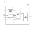
- FIG. 3 is a functional block diagram showing details of the battery state estimation device 110 according to the first embodiment of the present invention.
- the battery state estimating device 110 according to the present embodiment has functional blocks of a cell voltage acquiring unit 111, a reference cell information acquiring unit 112, a temporary SOC computing unit 113, and an SOC computing unit 114.
- Each of these functional blocks is realized as, for example, hardware configuring the battery state estimation device 110 or software executed by the CPU.
- CCV closed circuit voltage
- the reference cell information acquisition unit 112 sets a reference cell for a plurality of cells 401 included in the battery pack 400, and closes the open circuit voltage (CCV) and the open circuit voltage (OCV) of the reference cell, and charges the reference cell.
- a reference SOC value indicating a state is obtained.
- the reference cell information obtaining unit 112 determines the total battery voltage Vtotal, the battery current I, and the battery temperature T measured by the measuring unit 200 when the battery pack 400 is in the energized state.
- the average value of CCV, OCV, and SOC of each cell 401 is obtained as the CCV, OCV, and reference SOC value of the reference cell.
- these acquired values are output as CCVave, OCVave, and SOCave, respectively.
- the method of calculating CCVave, OCVave, and SOCave by the reference cell information acquisition unit 112 will be described later.
- SOC calculation unit 114 obtains an SOC value indicating the state of charge of each cell 401 based on SOCnx input from temporary SOC calculation unit 113 and SOCave input from reference cell information acquisition unit 112. Then, based on the SOC value obtained for each cell 401, a cell charge state SOCn is output. The method of calculating SOCn by SOC calculating section 114 will be described later.
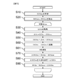
- FIG. 4 is a diagram showing a processing flow of the battery state estimation device 110 according to the first embodiment of the present invention.
- the battery state estimation device 110 of the present embodiment estimates the state of charge of each cell 401 by executing the processing flow shown in FIG. 4 at predetermined processing cycles when the battery pack 400 is in the energized state.
- the reference cell information acquisition unit 112 calculates an average cell voltage CCVave per cell of the battery pack 400.
- the reference cell information obtaining unit 112 calculates CCVave by obtaining the total voltage Vtotal from the measuring unit 200 and dividing the total voltage Vtotal by the number of cells of the assembled battery 400. Then, the calculated value of CCVave is output to provisional SOC calculating section 113.
- the reference cell information acquisition unit 112 calculates the average cell state of charge SOCave of the battery pack 400 and the average cell voltage OCVave per cell when the battery pack 400 is not energized.
- the reference cell information acquisition unit 112 for example, based on the known SOC value of the entire assembled battery 400 at a certain point in the past and the integration result of the battery current I acquired from the measuring unit 200, Is obtained, and this is defined as SOCave.
- the OCV value of the assembled battery 400 corresponding to the calculated SOCave is obtained using the relationship between the OCV and the SOC of the entire assembled battery 400 included in the characteristic information stored in the storage unit 120, and the OCV value is calculated. Is divided by the number of cells of the assembled battery 400 to calculate the OCVave.
- the calculated OCVave and SOCave values are output to provisional SOC calculating section 113 and SOC calculating section 114, respectively.
- the reference cell information acquisition unit 112 estimates the resistance value of the entire assembled battery 400 based on the battery temperature T acquired from the measurement unit 200, and calculates OCVave based on this and the CCVave obtained in step S10. It may be calculated.
- the SOCave can be calculated from the OCVave calculation result using the relationship between the OCV and the SOC of the entire battery pack 400 included in the characteristic information stored in the storage unit 120.
- the reference cell information acquisition unit 112 can calculate the SOCave and the OCVave by using an arbitrary method.
- the battery state estimating apparatus 110 sequentially executes the processing of steps S30 to S90 for each cell 401 of the assembled battery 400.
- step S30 the cell voltage acquisition unit 111 acquires the cell voltage CCVn of the target cell from the measurement unit 200. Then, the calculated value of CCVn is output to provisional SOC calculating section 113.
- step S40 the temporary SOC calculation unit 113 calculates a cell voltage difference ⁇ Vn between the target cell and the reference cell.
- the temporary SOC calculation unit 113 subtracts the average cell voltage CCVave input from the reference cell information obtaining unit 112 in step S10 from the cell voltage CCVn of the target cell input from the cell voltage obtaining unit 111 in step S30.
- the cell voltage difference ⁇ Vn is obtained by the following equation (1).
- ⁇ Vn CCVn-CCVave (1)
- step S50 the temporary SOC calculation unit 113 calculates the value of the temporary OCV of the target cell, that is, OCVnx.
- provisional SOC calculating section 113 calculates OCVnx by adding OCVave calculated in step S20 to cell voltage difference ⁇ Vn calculated in step S40. That is, in step S50, OCVnx is obtained by the following equation (2).
- OCVnx ⁇ Vn + OCVave (2)
- step S60 the temporary SOC calculation unit 113 converts the OCVnx calculated in step S50 into an SOC value, thereby calculating the SOCnx which is the temporary SOC value of the target cell.
- provisional SOC calculating section 113 converts OCVnx to SOCnx using the relationship between OCV and SOC of each cell included in the characteristic information stored in storage section 120. Then, the calculated SOCnx value is output to SOC calculating section 114.
- FIG. 5 is a diagram showing the relationship between the open circuit voltage OCV and SOC of each cell. This correspondence is determined by the characteristics of each cell 401 in the battery pack 400, and data defining the correspondence is stored in the storage unit 120 in advance as an SOC table.
- the temporary SOC calculation unit 113 can calculate the SOCnx, which is the temporary SOC of the target cell, by referring to the SOC table using the OCVnx calculated in step S50 as a key.
- the OCVnx calculated in step S50 is calculated using the cell voltage difference ⁇ Vn obtained from the cell voltage CCVn of the target cell during energization.
- the SOCnx calculated as the temporary SOC of the target cell in step S60 is obtained from the OCVnx. Therefore, the SOCnx is a measurement error of the cell voltage measurement unit 210, a difference in measurement timing between the CCVn of the target cell and the battery current I, and a difference in internal resistance of each cell (individual difference, temperature difference, deterioration state difference, etc.). And is not accurate. Therefore, in the present embodiment, the accurate SOC of the target cell is obtained from SOCnx by performing the calculation described below in the SOC calculation unit 114.
- step S70 the SOC calculator 114 calculates a temporary difference value ⁇ SOCnx of the SOC of the target cell with respect to the reference cell.
- SOC calculating section 114 calculates ⁇ SOCnx by subtracting the SOCave value input from reference cell information obtaining section 112 in step S20 from the SOCnx value input from temporary SOC calculating section 113 in step S60. I do. That is, in step S70, ⁇ SOCnx is obtained by the following equation (3).
- ⁇ SOCnx SOCnx ⁇ SOCave (3)
- step S80 the actual difference value ⁇ SOCn of the SOC of the target cell with respect to the reference cell is calculated by smoothing the provisional difference value ⁇ SOCnx calculated in step S70 by the SOC calculation unit 114.
- the smoothing process performed in step S80 is to smooth and smooth variations of the temporary difference value ⁇ SOCnx in each processing cycle, thereby reducing errors and noises included in the temporary difference value ⁇ SOCnx and real difference values. This is a process for calculating ⁇ SOCn.
- the smoothing process in step S80 is realized by, for example, a moving average process or a filter process using a predetermined digital filter such as a low-pass filter or a Kalman filter.
- the smoothing process may be performed by a weighted moving average in which a newer value is weighted more heavily.
- the weighting of each value can be determined according to an arbitrary processing method such as a linear weighted moving average, an exponential moving average, a modified moving average, and a triangular moving average.
- step S90 the SOC operation unit 114 calculates the SOC value of the target cell using the result of the smoothing process in step S80.
- SOC calculating section 114 adds the actual difference value ⁇ SOCn after the smoothing process obtained in step S80 to the value of SOCave input from reference cell information obtaining section 112 in step S20, thereby obtaining the value of the target cell.
- An SOC value SOCn is calculated. That is, in step S90, SOCn is obtained by the following equation (5).
- SOCn SOCave + ⁇ SOCn (5)
- step S90 After calculating the SOCn for the target cell in step S90, the process returns to step S30, and the processes of S30 to S90 are repeated.
- the processes of S30 to S90 can be performed on all the cells 401 as the target cells, the battery state estimation device 110 ends the processing flow of FIG.
- the actual difference value ⁇ SOCn is obtained by performing a smoothing process on the temporary difference value ⁇ SOCnx obtained by the above-described equation (3), and the actual difference value ⁇ SOCn is obtained. Is used to calculate the SOC value of the target cell by the above equation (5). Therefore, the SOC value of the target cell can be accurately obtained by simple processing without requiring complicated arithmetic processing and a complicated hardware configuration.
- the battery state estimation device 110 is a device that is connected to a battery pack 400 in which a plurality of cells 401 are connected in series, and estimates the charge state of a target cell using any one of the plurality of cells 401 as a target cell.
- the battery state estimation device 110 includes a cell voltage acquisition unit 111, a reference cell information acquisition unit 112, a temporary SOC calculation unit 113, and an SOC calculation unit 114.
- the cell voltage acquisition unit 111 acquires the measurement result of the closed circuit voltage CCVn of the target cell (Step S30).
- the reference cell information acquisition unit 112 sets a reference cell for the plurality of cells 401, and determines a closed circuit voltage CCVave and an open circuit voltage OCVave of the reference cell and an SOCave that is a reference SOC value indicating the state of charge of the reference cell.
- Acquire (Steps S10 and S20).
- the provisional SOC calculation unit 113 calculates SOCnx which is a provisional SOC value indicating a provisional state of charge of the target cell, based on the closed circuit voltage CCVn of the target cell and the closed circuit voltage CCVave and the open circuit voltage OCVave of the reference cell. (Steps S40 to S60).
- the SOC calculation unit 114 obtains SOCn, which is the SOC value indicating the state of charge of the target cell, using the result of smoothing the difference ⁇ SOCnx between SOCnx and SOCave (steps S70 to S90). With this configuration, it is possible to provide the battery state estimating device 110 capable of estimating the state of charge of each cell 401 of the battery pack 400 with low cost and high accuracy.
- the smoothing process performed in step S80 can include at least one of a moving average process and a filter process using a predetermined digital filter. In this way, it is possible to surely reduce the time variation in the difference ⁇ SOCnx between SOCnx and SOCave, and to appropriately and easily calculate the actual difference value ⁇ SOCn after the smoothing process required for obtaining SOCn. .
- the reference cell information acquisition unit 112 sets CCVave and SOCave, which are the average values of the closed circuit voltage and the state of charge of the plurality of cells 401, as the closed circuit voltage and the reference SOC value of the reference cell, respectively.
- CCVave and SOCave are the average values of the closed circuit voltage and the state of charge of the plurality of cells 401, as the closed circuit voltage and the reference SOC value of the reference cell, respectively.
- OCVave as an open circuit voltage of the reference cell is obtained based on the obtained SOCave.
- FIG. 6 is a functional block diagram showing details of the battery state estimation device 110 according to the second embodiment of the present invention.
- the battery state estimating device 110 of the present embodiment includes, in addition to the functional blocks of the cell voltage obtaining unit 111, the reference cell information obtaining unit 112, the temporary SOC calculating unit 113, and the SOC calculating unit 114 described in the first embodiment, Further, a weight coefficient calculation unit 115 is provided.
- Weight coefficient calculating section 115 calculates weight coefficient W based on battery current I and battery temperature T measured by measuring section 200 when battery pack 400 is in the energized state.
- the weight coefficient W is output from the weight coefficient calculation unit 115 to the SOC calculation unit 114 and is used when the SOC calculation unit 114 performs a smoothing process. The method of calculating the weight coefficient W by the weight coefficient calculation unit 115 will be described later.
- FIG. 7 is a diagram showing a processing flow of the battery state estimation device 110 according to the second embodiment of the present invention.
- the battery state estimating device 110 of the present embodiment estimates the state of charge of each cell 401 by executing the processing flow shown in FIG. 7 at predetermined processing cycles when the battery pack 400 is in the energized state.
- steps S10 to S60 processes similar to those described in the first embodiment are respectively performed.
- the weight coefficient calculation unit 115 calculates a weight coefficient W.
- the weight coefficient calculating unit 115 calculates the weight coefficient W by, for example, the following equation (6) based on the absolute value of the battery current I representing the current flowing through the target cell and the internal resistance value of the target cell.
- R represents the internal resistance value of the target cell
- G1 and G2 represent behavior coefficients for characterizing the behavior of the smoothing process using the weight coefficient W. The relationship between the behavior coefficients G1 and G2 and the behavior of the smoothing process will be described later.
- W 1 / ⁇ (1+
- the internal resistance R of the target cell is stored in the storage unit 120 as characteristic information in advance. Since the internal resistance R varies depending on the state of charge of the target cell, the battery temperature T, and the like, an individual value is stored in the storage unit 120 for each of these combinations.
- characteristic information that defines the correspondence between the internal resistance R and the battery temperature T is stored as a resistance table.
- the weight coefficient calculation unit 115 acquires the internal resistance R from the resistance table based on the battery temperature T, and calculates the weight coefficient W using Expression (6).
- the SOC calculation unit 114 temporarily calculates the SOC of the target cell with respect to the reference cell in the same manner as described in the first embodiment. Is calculated.
- step S80 the actual difference value ⁇ SOCn of the SOC of the target cell with respect to the reference cell is calculated by smoothing the temporary difference value ⁇ SOCnx calculated in step S70 by the SOC calculation unit 114.
- the SOC calculation unit 114 in the present embodiment uses the weighting factor W calculated by the weighting factor calculation unit 115 in step S61 to calculate the temporary difference value ⁇ SOCnx before the smoothing process obtained in the current process.
- the smoothing process is performed by weighting and adding the actual difference value ⁇ SOCn after the smoothing process used in the calculation of the SOC value of the target cell obtained in the previous process.
- step S90 When the actual difference value ⁇ SOCn is calculated by performing a smoothing process using the weight coefficient W in step S80, in step S90, using the result, the SOCn, which is the SOC value of the target cell, is calculated by the above-described equation (5). calculate. After the SOCn for the target cell is calculated in step S90, the process returns to step S30 as in the first embodiment, and the processes in S30 to S90 are repeated. When the processes of S30 to S90 have been performed with all the cells 401 as the target cells, the battery state estimating apparatus 110 ends the processing flow of FIG.
- the behavior coefficient G1 is a coefficient relating to the entirety of the above-described equation (6), and is related to the stability of the smoothing process and the update frequency. Specifically, when the value of the behavior coefficient G1 is small, the stability of the actual difference value ⁇ SOCn (t) calculated by Expression (7) decreases, while the update frequency increases. As a result, instead of increasing the fluctuation range of the SOCn of the target cell calculated for each processing cycle, the followability to the actual SOC change is increased.
- the value of the behavior coefficient G1 is large, the stability of the actual difference value ⁇ SOCn calculated by Expression (7) is improved, while the update frequency is reduced. As a result, the fluctuation range of the SOCn of the target cell calculated for each processing cycle is reduced, but the followability to the actual SOC change is reduced.
- a value equal to or greater than 1 and equal to or less than a predetermined value such as 100 is set as the behavior coefficient G1.
- the behavior coefficient G2 is a coefficient relating to the absolute value of the battery current I in the above equation (6), and is related to the degree of influence of the battery current I on the smoothing process. Specifically, when the value of the behavior coefficient G2 is small, the degree of influence of the battery current I on the actual difference value ⁇ SOCn (t) calculated by the equation (7) decreases. As a result, the behavior of the SOCn of the target cell calculated for each processing cycle is less affected by the battery current I. Conversely, when the value of the behavior coefficient G2 is large, the degree of influence of the battery current I on the actual difference value ⁇ SOCn (t) calculated by the equation (7) increases.
- the SOCn of the target cell calculated for each processing cycle has higher stability if the absolute value of the battery current I is larger, and the update frequency increases if the absolute value of the battery current I is smaller.
- the period in which the absolute value of the battery current I is large does not normally continue over a long period of time, it is necessary to secure an appropriate update frequency for the SOCn of the target cell even if the value of the behavior coefficient G2 is increased to some extent.
- a value equal to or greater than 0 is set as the behavior coefficient G2.
- values according to the characteristics of each cell 401 of the assembled battery 400 are stored in the storage unit 120 in advance as the values of the behavior coefficients G1 and G2.
- the values of the behavior coefficients G1 and G2 that change according to the battery temperature T, the battery current I, the degree of deterioration of each cell 401, and the like are stored in the storage unit 120 as map information, and the behavior is referred to by referring to this map information.
- the values of the coefficients G1 and G2 may be determined.
- the battery state estimating device 110 includes a weight coefficient calculating unit 115 that calculates a weight coefficient W based on the absolute value of the battery current I flowing through the target cell and the internal resistance value R of the target cell.
- the moving average processing included in the smoothing processing performed in step S80 includes a temporary difference ⁇ SOCnx between the current SOCnx and SOCave and an actual difference ⁇ SOCn (after the smoothing processing used for calculating the previous SOC value of the target cell).
- t-1) is weighted and added using the weighting coefficient W according to equation (7). With this configuration, the accuracy of calculating the SOC value of the target cell can be improved.
- FIG. 8 is a functional block diagram showing details of the battery state estimation device 110 according to the third embodiment of the present invention.
- the battery state estimating device 110 of the present embodiment includes the functional blocks of the cell voltage obtaining unit 111, the reference cell information obtaining unit 112, the temporary SOC calculating unit 113, and the SOC calculating unit 114 described in the first embodiment.
- the battery current I is also input to the SOC calculation unit 114. Except for this point, it is the same as the functional block of FIG. 3 in the first embodiment.
- the SOC calculation unit 114 determines whether or not to perform the smoothing process based on the battery current I. When it is determined that the smoothing process is not to be performed, the SOC operation unit 114 holds the SOC value obtained in the previous process for each cell 401 as it is, and uses it as the current process result.
- FIG. 9 is a diagram showing a processing flow of the battery state estimating device 110 according to the third embodiment of the present invention.
- the battery state estimation device 110 of the present embodiment estimates the state of charge of each cell 401 by executing the processing flow shown in FIG. 9 at predetermined processing cycles when the battery pack 400 is in the energized state.
- steps S10 to S20 the same processing as that described in the first embodiment is performed.
- step S21 the SOC calculation unit 114 determines whether or not the absolute value of the battery current I is larger than a predetermined current threshold value Ith. If the absolute value of the battery current I exceeds the current threshold value Ith, the process proceeds to step S22; otherwise, the process proceeds to step S30.
- step S30 to S90 each of the cells 401 of the battery pack 400 is set as a target cell, and the same processing as that described in the first embodiment is performed.
- the battery state estimating device 110 ends the processing flow of FIG.
- step S22 the SOC operation unit 114 holds the value of the SOC of each cell obtained in the previous process. In this case, the SOC calculation unit 114 does not perform the smoothing process.
- the battery state estimating device 110 ends the processing flow in FIG.
- the SOC calculation unit 114 holds the previous SOC value without performing the smoothing process.
- the smoothing process is performed. By not performing this, it is possible to improve the calculation accuracy of the SOC value of the target cell.
- the previous SOC value when the absolute value of the battery current I flowing through the target cell exceeds a predetermined value, the previous SOC value is held without performing the smoothing process. It is also possible to determine the presence or absence of the smoothing process using conditions other than the above. For example, the amount of time change of the battery current I flowing through the target cell may be measured, and when the absolute value exceeds a predetermined value, the previous SOC value may be held without performing the smoothing process. Even in this case, the same operation and effect as the above (5) can be obtained. The presence or absence of the smoothing process may be determined using another condition.
- the battery state estimating device 110 determines whether or not the actual difference value ⁇ SOCn after the smoothing process obtained by the SOC calculation unit 114 has changed abruptly.
- An example in which a change amount restriction process for restricting is performed will be described.
- the configuration of the battery system 1000 according to the present embodiment, the configurations of the measuring unit 200 and the assembled battery 400, and the functional blocks of the battery state estimation device 110 are the same as those described with reference to FIGS. The description is omitted below.
- FIG. 10 is a diagram showing a processing flow of the battery state estimating device 110 according to the fourth embodiment of the present invention.
- the battery state estimating device 110 of the present embodiment estimates the state of charge of each cell 401 by executing the processing flow shown in FIG. 10 at predetermined processing cycles when the battery pack 400 is in the energized state.
- steps S10 to S80 processes similar to those described in the first embodiment are respectively performed.
- step S81 the SOC calculation unit 114 determines whether the actual difference value ⁇ SOCn after the smoothing process calculated in step S80 is larger than a predetermined difference threshold value Sth. If the actual difference value ⁇ SOCn exceeds the difference threshold value Sth, the process proceeds to step S82; otherwise, the process proceeds to step S90.
- step S82 the actual difference value ⁇ SOCn after the smoothing process calculated in step S80 is replaced with a difference threshold value Sth.
- the actual difference value ⁇ SOCn after the smoothing process is limited to be equal to or smaller than the difference threshold value Sth.
- the SOC calculation unit 114 performs the processing in step S90 using the restricted actual difference value ⁇ SOCn replaced with the difference threshold value Sth, thereby reducing the SOCn, which is the SOC value of the target cell. calculate.
- the battery state estimating apparatus 110 ends the processing flow of FIG.
- the SOC calculation unit 114 performs a variation limiting process of limiting the actual difference value ⁇ SOCn after the smoothing process to a predetermined value or less.
- FIG. 11 is a functional block diagram showing details of the battery state estimation device 110 according to the fifth embodiment of the present invention.
- the battery state estimating device 110 of the present embodiment includes the functional blocks of the cell voltage obtaining unit 111, the reference cell information obtaining unit 112, the temporary SOC calculating unit 113, and the SOC calculating unit 114 described in the first embodiment. I have.
- the reference cell information acquisition unit 112 sets a specific cell 401 among a plurality of cells 401 included in the battery pack 400 as a reference cell, and when the battery pack 400 is in an energized state, the measuring unit 200 The measured cell voltage Vref of the reference cell, the battery current I and the battery temperature T are acquired. Then, the obtained cell voltage Vref is output as the reference cell voltage CCVref representing the closed circuit voltage (CCV) of the reference cell. Further, based on the obtained cell voltage Vref, battery current I and battery temperature T, the open circuit voltage (OCV) and the SOC value of the cell reference cell are calculated, and these calculation results are used as the open circuit voltage OCVref of the reference cell. And a reference cell charge state SOCref.
- the cell 401 from which the values of OCV and SOC can be acquired as accurately as possible is used as the reference cell.
- the temperature of the cell 401 can be accurately measured, so that the OCV of the cell 401 can be calculated with high accuracy.
- the SOC can be calculated with high accuracy from the OCV.
- the cell 401 whose CCV is measured at the timing closest to the measurement timing of the battery current I is It may be a reference cell.
- the measurement timing of the battery current I and the measurement timing of the CCV of the cell 401 are substantially synchronized, and therefore, the OCV is increased from the CCV of the cell 401 using the following equivalent circuit equation (8). Accuracy can be calculated. Further, the SOC can be calculated with high accuracy from the OCV.
- CCV OCV ⁇ I ⁇ R (8)
- the reference cell information acquisition unit 112 can set an arbitrary cell 401 as a reference cell and acquire CCVref, OCVref, and SOCref for the reference cell.
- FIG. 12 is a diagram showing a processing flow of the battery state estimating device 110 according to the fifth embodiment of the present invention.
- the battery state estimation device 110 of the present embodiment estimates the state of charge of each cell 401 by executing the processing flow shown in FIG. 12 at predetermined processing cycles when the battery pack 400 is in the energized state.
- the reference cell information acquisition unit 112 acquires the reference cell voltage CCVref.
- the reference cell information acquisition unit 112 selects a preset reference cell from the plurality of cells 401 of the battery pack 400 based on the above-described viewpoint, and measures the measurement result of the cell voltage of the reference cell. Obtained from the unit 200. Then, it outputs the obtained cell voltage value to provisional SOC calculating section 113 as reference cell voltage CCVref.
- the reference cell information acquiring unit 112 calculates the reference cell charge state SOCref and the cell voltage OCVref when the reference cell is not energized.
- the reference cell information acquisition unit 112 estimates the resistance value R of the reference cell based on the battery temperature T acquired from the measurement unit 200, and acquires the resistance value R in step S10A using the above-described equivalent circuit equation (8).
- OCVref corresponding to the obtained CCVref is obtained.
- the SOCref can be calculated from the OCVref calculation result using the relationship between the OCV and the SOC of the reference cell included in the characteristic information stored in the storage unit 120. Note that SOCref and OCVref may be calculated by other methods.
- the reference cell information acquisition unit 112 outputs the calculated values of the OCVref and the SOCref to the provisional SOC calculation unit 113 and the SOC calculation unit 114, respectively.
- step S40A the temporary SOC calculator 113 calculates the cell voltage difference ⁇ Vn between the target cell and the reference cell.
- the temporary SOC calculation unit 113 subtracts the reference cell voltage CCVref input from the reference cell information acquisition unit 112 in step S10A from the cell voltage CCVn of the target cell input from the cell voltage acquisition unit 111 in step S30.
- the cell voltage difference ⁇ Vn is obtained by the following equation (1A).
- ⁇ Vn CCVn ⁇ CCVref (1A)
- step S50A the temporary SOC calculation unit 113 calculates OCVnx, which is the value of the temporary OCV of the target cell.
- temporary SOC calculating section 113 calculates OCVnx by adding OCVref calculated in step S20A to cell voltage difference ⁇ Vn calculated in step S40A. That is, in step S50A, OCVnx is obtained by the following equation (2A).
- OCVnx ⁇ Vn + OCVref (2A)
- step S70A the SOC calculating unit 114 calculates a temporary difference value ⁇ SOCnx of the SOC of the target cell with respect to the reference cell.
- step S90A the SOC calculation unit 114 calculates the SOC value of the target cell using the result of the smoothing processing in step S80. I do.
- SOC calculating section 114 adds the actual difference value ⁇ SOCn after the smoothing process obtained in step S80 to the value of SOCref input from reference cell information obtaining section 112 in step S20A, thereby obtaining the value of the target cell.
- An SOC value SOCn is calculated. That is, in step S90A, SOCn is obtained by the following equation (5A).
- SOCn SOCref + ⁇ SOCn (5A)
- step S90A After calculating the SOCn for the target cell in step S90A, the process returns to step S30 and repeats the processing of S30 to S90A.
- the battery state estimating device 110 ends the processing flow of FIG.
- a temperature sensor is provided at a position corresponding to at least one of the plurality of cells 401.
- the reference cell information acquisition unit 112 sets the cell 401 corresponding to the installation position of the temperature sensor as a reference cell.
- the cell voltage acquisition unit 111 acquires, as the closed circuit voltage CCVn of the target cell, the closed circuit voltage of each cell 401 of the battery pack 400 that is sequentially measured in each predetermined cycle.
- the reference cell information acquisition unit 112 sets the cell 401 whose closed circuit voltage is measured at the timing closest to the measurement timing of the battery current I among the plurality of cells 401 of the battery pack 400 as the reference cell. Because of this, the closed circuit voltage CCVref, the open circuit voltage OCVref, and the reference cell charge state SOCref of the reference cell can be accurately obtained.
- FIG. 13 is a block diagram showing a configuration of a battery system 1000A according to the sixth embodiment of the present invention.
- the battery system 1000A of the present embodiment includes a battery control device 100A, a measuring unit 200, an output unit 300, an assembled battery 400, and a balancing unit 500. Note that the measurement unit 200, the output unit 300, and the battery pack 400 are the same as those of the battery system 1000 described in the first embodiment, respectively, and thus description thereof will be omitted below.
- the battery control device 100A is a device that controls the operation of the battery pack 400, and includes a battery state estimation device 110, a storage unit 120, and a balancing control device 130.
- the battery state estimating device 110 is a device that calculates the SOC of each cell of the battery pack 400, and may be any of those described in the first to fifth embodiments.
- the storage unit 120 stores characteristic information that can be known in advance, such as the internal resistance R, the polarization voltage Vp, the charging efficiency, the allowable current, and the total capacity of each cell of the battery pack 400, as described in the first embodiment. I remember.
- the balancing control device 130 outputs a signal for controlling the discharge time of each cell to the balancing unit 500 based on the SOC value of each cell obtained by the battery state estimation device 110.
- the balancing unit 500 has a plurality of balancing switches (not shown) provided corresponding to each cell of the battery pack 400. The operation of each balancing switch is controlled according to an input signal from the balancing control device 130. As a result, the balancing control of the battery pack 400 is performed, and the variation in the SOC of each cell is suppressed.
- the battery control device 100A includes a battery state estimation device 110, and a balancing control device 130 that controls balancing of the battery pack 400 based on the SOC value of each cell obtained by the battery state estimation device 110.
Landscapes
- Engineering & Computer Science (AREA)
- General Physics & Mathematics (AREA)
- Physics & Mathematics (AREA)
- General Chemical & Material Sciences (AREA)
- Chemical Kinetics & Catalysis (AREA)
- Electrochemistry (AREA)
- Chemical & Material Sciences (AREA)
- Manufacturing & Machinery (AREA)
- Power Engineering (AREA)
- Microelectronics & Electronic Packaging (AREA)
- Secondary Cells (AREA)
- Tests Of Electric Status Of Batteries (AREA)
- Charge And Discharge Circuits For Batteries Or The Like (AREA)
Abstract
L'invention concerne un dispositif d'estimation d'état de cellule connecté à un bloc-batterie dans lequel une pluralité de cellules sont connectées en série, le dispositif d'estimation d'état de cellule estimant l'état de charge d'une cellule d'objet constituant une cellule quelconque de la pluralité de cellules et comprenant : une unité d'acquisition de tension de cellule permettant d'acquérir le résultat de mesure de la tension de circuit fermé de la cellule d'objet; une unité d'acquisition d'informations de cellule de référence permettant de définir une cellule de référence pour la pluralité de cellules et d'acquérir la tension de circuit fermé et la tension de circuit ouvert de la cellule de référence, et une valeur de SOC de référence représentant l'état de charge de la cellule de référence; une unité de calcul de SOC provisoire permettant de déterminer une valeur de SOC provisoire représentant l'état de charge provisoire de la cellule d'objet en fonction de la tension de circuit fermé de la cellule d'objet, et de la tension de circuit fermé et de la tension de circuit ouvert de la cellule de référence; et une unité de calcul de SOC permettant de déterminer une valeur de SOC représentant l'état de charge de la cellule d'objet à l'aide du résultat du lissage de la différence entre la valeur de SOC provisoire et la valeur de SOC de référence.
Priority Applications (4)
| Application Number | Priority Date | Filing Date | Title |
|---|---|---|---|
| EP19844424.2A EP3832331B1 (fr) | 2018-07-30 | 2019-03-18 | Dispositif d'estimation d'état de cellule et dispositif de commande de cellule |
| JP2020534048A JP6947937B2 (ja) | 2018-07-30 | 2019-03-18 | 電池状態推定装置、電池制御装置 |
| CN201980050862.6A CN112912747B (zh) | 2018-07-30 | 2019-03-18 | 电池状态推算装置和电池控制装置 |
| US17/264,440 US12117497B2 (en) | 2018-07-30 | 2019-03-18 | Battery status estimation apparatus and battery control apparatus |
Applications Claiming Priority (2)
| Application Number | Priority Date | Filing Date | Title |
|---|---|---|---|
| JP2018142471 | 2018-07-30 | ||
| JP2018-142471 | 2018-07-30 |
Publications (1)
| Publication Number | Publication Date |
|---|---|
| WO2020026509A1 true WO2020026509A1 (fr) | 2020-02-06 |
Family
ID=69232178
Family Applications (1)
| Application Number | Title | Priority Date | Filing Date |
|---|---|---|---|
| PCT/JP2019/011056 Ceased WO2020026509A1 (fr) | 2018-07-30 | 2019-03-18 | Dispositif d'estimation d'état de cellule et dispositif de commande de cellule |
Country Status (5)
| Country | Link |
|---|---|
| US (1) | US12117497B2 (fr) |
| EP (1) | EP3832331B1 (fr) |
| JP (1) | JP6947937B2 (fr) |
| CN (1) | CN112912747B (fr) |
| WO (1) | WO2020026509A1 (fr) |
Cited By (3)
| Publication number | Priority date | Publication date | Assignee | Title |
|---|---|---|---|---|
| WO2022177291A1 (fr) * | 2021-02-16 | 2022-08-25 | 주식회사 엘지에너지솔루션 | Système de gestion de batterie, bloc-batterie, système de stockage d'énergie et procédé de gestion de batterie |
| JP2023024201A (ja) * | 2021-08-06 | 2023-02-16 | トヨタ自動車株式会社 | バッテリ管理装置および方法 |
| KR102877721B1 (ko) * | 2024-12-31 | 2025-10-31 | (주)모아소프트 | 차량용 배터리 상태 추정 값과 실제 값을 이용한 파라미터 보정 방법 |
Families Citing this family (7)
| Publication number | Priority date | Publication date | Assignee | Title |
|---|---|---|---|---|
| KR102521576B1 (ko) * | 2019-03-18 | 2023-04-12 | 주식회사 엘지에너지솔루션 | 배터리 관리 장치 |
| CN113884894B (zh) * | 2021-11-15 | 2023-07-21 | 长沙理工大学 | 基于外部特性的电池簇不一致性在线监测方法 |
| KR20250037010A (ko) * | 2023-09-07 | 2025-03-17 | 주식회사 엘지에너지솔루션 | 배터리 진단 장치 및 그의 동작 방법 |
| CN117007979B (zh) * | 2023-10-07 | 2024-07-09 | 深圳市众航物联网有限公司 | 基于数据驱动的电源输出掉电异常预警方法 |
| EP4624954A1 (fr) * | 2024-03-28 | 2025-10-01 | Siemens Aktiengesellschaft | Procédé de détermination d'au moins une tension de test spécifique pour un élément de batterie, produit-programme informatique, support d'enregistrement lisible et dispositif de mesure |
| DE102024001682A1 (de) * | 2024-05-24 | 2025-11-27 | Mercedes-Benz Group AG | Verfahren zur Ermittlung des Ladezustands von Batteriezellen, Recheneinheit, Batterie und Fahrzeug |
| CN119030106B (zh) * | 2024-10-29 | 2025-06-03 | 深圳市德兰明海新能源股份有限公司 | 串联电芯均衡方法、装置以及电子设备 |
Citations (6)
| Publication number | Priority date | Publication date | Assignee | Title |
|---|---|---|---|---|
| JP2005331482A (ja) * | 2004-05-21 | 2005-12-02 | Fuji Heavy Ind Ltd | 蓄電デバイスの残存容量演算装置 |
| JP2011041452A (ja) * | 2009-07-17 | 2011-02-24 | Toshiba Corp | 組電池装置及び車両 |
| JP2011530697A (ja) | 2008-08-08 | 2011-12-22 | エルジー・ケム・リミテッド | バッテリーセルの電圧変化挙動を用いたセルバランス装置及び方法 |
| JP2013253857A (ja) * | 2012-06-07 | 2013-12-19 | Calsonic Kansei Corp | 組電池のセルの状態推定装置 |
| JP2018100841A (ja) * | 2016-12-19 | 2018-06-28 | トヨタ自動車株式会社 | 蓄電システム |
| JP2018142471A (ja) | 2017-02-28 | 2018-09-13 | 国立研究開発法人産業技術総合研究所 | マーキング方法、マーキング装置、およびマーキングされた物品 |
Family Cites Families (22)
| Publication number | Priority date | Publication date | Assignee | Title |
|---|---|---|---|---|
| JP4925060B2 (ja) * | 2007-10-19 | 2012-04-25 | 本田技研工業株式会社 | 電池状態推定装置 |
| JP5133926B2 (ja) * | 2009-03-26 | 2013-01-30 | 株式会社日立製作所 | 車両用電池システム |
| JP5020307B2 (ja) * | 2009-12-07 | 2012-09-05 | 三菱電機株式会社 | 電気負荷の駆動制御装置 |
| US9263773B2 (en) * | 2010-01-19 | 2016-02-16 | Gs Yuasa International Ltd. | Secondary battery state of charge determination apparatus, and method of determining state of charge of secondary battery |
| JP2014211307A (ja) * | 2011-08-30 | 2014-11-13 | 三洋電機株式会社 | バッテリシステム、充電状態推定装置、電動車両、移動体、電力貯蔵装置および電源装置 |
| JP6065561B2 (ja) * | 2012-03-08 | 2017-01-25 | 日産自動車株式会社 | 二次電池の制御装置およびsoc検出方法 |
| JP5863603B2 (ja) * | 2012-08-24 | 2016-02-16 | 日立オートモティブシステムズ株式会社 | 電池状態推定装置、電池制御装置、電池システム、電池状態推定方法 |
| JP6101714B2 (ja) * | 2013-01-25 | 2017-03-22 | 日立オートモティブシステムズ株式会社 | 電池制御装置、電池システム |
| WO2014188562A1 (fr) * | 2013-05-23 | 2014-11-27 | 日立オートモティブシステムズ株式会社 | Dispositif de commande de batterie |
| WO2015132891A1 (fr) * | 2014-03-05 | 2015-09-11 | 株式会社日立製作所 | Module de batterie secondaire |
| KR101779941B1 (ko) * | 2014-12-29 | 2017-09-19 | 주식회사 엘지화학 | 배터리 충전 상태 측정 장치 및 방법 |
| CN107431367B (zh) * | 2015-03-02 | 2020-08-11 | 日本汽车能源株式会社 | 电池控制装置和车辆系统 |
| WO2016158396A1 (fr) * | 2015-03-31 | 2016-10-06 | 日立オートモティブシステムズ株式会社 | Dispositif de commande de batterie et système de véhicule électrique |
| JP6383704B2 (ja) * | 2015-07-02 | 2018-08-29 | 日立オートモティブシステムズ株式会社 | 電池制御装置 |
| JP6787660B2 (ja) * | 2015-12-10 | 2020-11-18 | ビークルエナジージャパン株式会社 | 電池制御装置、動力システム |
| US10845417B2 (en) * | 2016-01-29 | 2020-11-24 | Vehicle Energy Japan, Inc. | Battery state estimation device, battery control device, battery system, battery state estimation method |
| JP6588632B2 (ja) * | 2016-05-18 | 2019-10-09 | 日立オートモティブシステムズ株式会社 | 電池制御装置 |
| WO2018043222A1 (fr) * | 2016-08-30 | 2018-03-08 | パナソニックIpマネジメント株式会社 | Dispositif de gestion et système de stockage d'énergie |
| WO2018089763A2 (fr) * | 2016-11-10 | 2018-05-17 | Camx Power, L.L.C. | Systèmes et procédés d'évaluation d'une qualité d'une cellule électrochimique |
| JP7185437B2 (ja) * | 2018-07-30 | 2022-12-07 | ビークルエナジージャパン株式会社 | 電池管理装置、電池管理方法、電力貯蔵システム |
| JP7089049B2 (ja) * | 2018-10-12 | 2022-06-21 | ビークルエナジージャパン株式会社 | 電池制御装置 |
| CN112969929B (zh) * | 2018-10-26 | 2024-06-21 | 日本汽车能源株式会社 | 电池控制装置 |
-
2019
- 2019-03-18 WO PCT/JP2019/011056 patent/WO2020026509A1/fr not_active Ceased
- 2019-03-18 US US17/264,440 patent/US12117497B2/en active Active
- 2019-03-18 JP JP2020534048A patent/JP6947937B2/ja active Active
- 2019-03-18 EP EP19844424.2A patent/EP3832331B1/fr active Active
- 2019-03-18 CN CN201980050862.6A patent/CN112912747B/zh active Active
Patent Citations (6)
| Publication number | Priority date | Publication date | Assignee | Title |
|---|---|---|---|---|
| JP2005331482A (ja) * | 2004-05-21 | 2005-12-02 | Fuji Heavy Ind Ltd | 蓄電デバイスの残存容量演算装置 |
| JP2011530697A (ja) | 2008-08-08 | 2011-12-22 | エルジー・ケム・リミテッド | バッテリーセルの電圧変化挙動を用いたセルバランス装置及び方法 |
| JP2011041452A (ja) * | 2009-07-17 | 2011-02-24 | Toshiba Corp | 組電池装置及び車両 |
| JP2013253857A (ja) * | 2012-06-07 | 2013-12-19 | Calsonic Kansei Corp | 組電池のセルの状態推定装置 |
| JP2018100841A (ja) * | 2016-12-19 | 2018-06-28 | トヨタ自動車株式会社 | 蓄電システム |
| JP2018142471A (ja) | 2017-02-28 | 2018-09-13 | 国立研究開発法人産業技術総合研究所 | マーキング方法、マーキング装置、およびマーキングされた物品 |
Non-Patent Citations (1)
| Title |
|---|
| See also references of EP3832331A4 |
Cited By (5)
| Publication number | Priority date | Publication date | Assignee | Title |
|---|---|---|---|---|
| WO2022177291A1 (fr) * | 2021-02-16 | 2022-08-25 | 주식회사 엘지에너지솔루션 | Système de gestion de batterie, bloc-batterie, système de stockage d'énergie et procédé de gestion de batterie |
| US12474380B2 (en) | 2021-02-16 | 2025-11-18 | Lg Energy Solution, Ltd. | Battery management system, battery pack, energy storage system and battery management method |
| JP2023024201A (ja) * | 2021-08-06 | 2023-02-16 | トヨタ自動車株式会社 | バッテリ管理装置および方法 |
| JP7619205B2 (ja) | 2021-08-06 | 2025-01-22 | トヨタ自動車株式会社 | バッテリ管理装置および方法 |
| KR102877721B1 (ko) * | 2024-12-31 | 2025-10-31 | (주)모아소프트 | 차량용 배터리 상태 추정 값과 실제 값을 이용한 파라미터 보정 방법 |
Also Published As
| Publication number | Publication date |
|---|---|
| EP3832331A1 (fr) | 2021-06-09 |
| US12117497B2 (en) | 2024-10-15 |
| CN112912747B (zh) | 2023-07-11 |
| EP3832331B1 (fr) | 2023-08-02 |
| JPWO2020026509A1 (ja) | 2021-04-08 |
| US20210311127A1 (en) | 2021-10-07 |
| CN112912747A (zh) | 2021-06-04 |
| JP6947937B2 (ja) | 2021-10-13 |
| EP3832331A4 (fr) | 2022-05-04 |
Similar Documents
| Publication | Publication Date | Title |
|---|---|---|
| JP6947937B2 (ja) | 電池状態推定装置、電池制御装置 | |
| JP7292404B2 (ja) | バッテリ健全状態の推定方法 | |
| KR102035678B1 (ko) | 배터리 노화상태 산출 방법 및 장치 | |
| JP6509725B2 (ja) | バッテリの充電状態の推定 | |
| US8046181B2 (en) | Apparatus and method for estimating state of health of battery based on battery voltage variation pattern | |
| JP7036605B2 (ja) | 組電池の状態推定装置及び組電池の状態推定方法 | |
| JP2020508442A (ja) | バッテリー充電状態推定装置及び方法 | |
| KR102572652B1 (ko) | 배터리의 충전상태를 추정하는 방법 | |
| US20140055100A1 (en) | Battery state estimation system, battery control system, battery system, and battery state estimation method | |
| CN110914696A (zh) | 用于在电池的操作期间估计电池开路池格电压、充电状态以及健康状态的方法和系统 | |
| JP7552995B2 (ja) | エネルギー貯蔵システムの充電容量算出装置及び方法 | |
| KR102722271B1 (ko) | 배터리 관리 장치, 배터리 관리 방법 및 배터리팩 | |
| JP6867478B2 (ja) | 電池制御装置および車両システム | |
| CN113853524B (zh) | 用于估计电池状态的方法 | |
| JP2015038444A (ja) | 二次電池の残量推定方法及びその装置 | |
| JP6895541B2 (ja) | 二次電池監視装置、二次電池状態演算装置および二次電池状態推定方法 | |
| CN116559689B (zh) | 使用过电位的等效恒定电流模型的电池状态估计 | |
| CN116699431A (zh) | 基于多个滞后渡越速率的电池状态估计 | |
| KR102859090B1 (ko) | 배터리 soh 추정 방법 및 이를 적용한 배터리 팩 | |
| JP5851514B2 (ja) | 電池制御装置、二次電池システム | |
| JP7089049B2 (ja) | 電池制御装置 | |
| WO2018025350A1 (fr) | Dispositif d'estimation, programme d'estimation et dispositif de commande de charge | |
| JP2021144886A (ja) | 電池管理装置、電池管理システム及び電池管理方法 | |
| WO2018029849A1 (fr) | Dispositif d'estimation, programme d'estimation et dispositif de commande de charge | |
| JP6827527B2 (ja) | 電池制御装置 |
Legal Events
| Date | Code | Title | Description |
|---|---|---|---|
| 121 | Ep: the epo has been informed by wipo that ep was designated in this application |
Ref document number: 19844424 Country of ref document: EP Kind code of ref document: A1 |
|
| ENP | Entry into the national phase |
Ref document number: 2020534048 Country of ref document: JP Kind code of ref document: A |
|
| NENP | Non-entry into the national phase |
Ref country code: DE |
|
| ENP | Entry into the national phase |
Ref document number: 2019844424 Country of ref document: EP Effective date: 20210301 |