EP2701164A2 - Elektromagnetvorrichtung - Google Patents
Elektromagnetvorrichtung Download PDFInfo
- Publication number
- EP2701164A2 EP2701164A2 EP13178733.5A EP13178733A EP2701164A2 EP 2701164 A2 EP2701164 A2 EP 2701164A2 EP 13178733 A EP13178733 A EP 13178733A EP 2701164 A2 EP2701164 A2 EP 2701164A2
- Authority
- EP
- European Patent Office
- Prior art keywords
- yoke
- auxiliary
- iron core
- end portion
- permanent magnet
- Prior art date
- Legal status (The legal status is an assumption and is not a legal conclusion. Google has not performed a legal analysis and makes no representation as to the accuracy of the status listed.)
- Granted
Links
Images


Classifications
-
- H—ELECTRICITY
- H01—ELECTRIC ELEMENTS
- H01H—ELECTRIC SWITCHES; RELAYS; SELECTORS; EMERGENCY PROTECTIVE DEVICES
- H01H50/00—Details of electromagnetic relays
- H01H50/16—Magnetic circuit arrangements
- H01H50/36—Stationary parts of magnetic circuit, e.g. yoke
-
- H—ELECTRICITY
- H01—ELECTRIC ELEMENTS
- H01F—MAGNETS; INDUCTANCES; TRANSFORMERS; SELECTION OF MATERIALS FOR THEIR MAGNETIC PROPERTIES
- H01F7/00—Magnets
- H01F7/06—Electromagnets; Actuators including electromagnets
- H01F7/08—Electromagnets; Actuators including electromagnets with armatures
- H01F7/081—Magnetic constructions
-
- H—ELECTRICITY
- H01—ELECTRIC ELEMENTS
- H01F—MAGNETS; INDUCTANCES; TRANSFORMERS; SELECTION OF MATERIALS FOR THEIR MAGNETIC PROPERTIES
- H01F7/00—Magnets
- H01F7/06—Electromagnets; Actuators including electromagnets
- H01F7/08—Electromagnets; Actuators including electromagnets with armatures
- H01F7/121—Guiding or setting position of armatures, e.g. retaining armatures in their end position
- H01F7/122—Guiding or setting position of armatures, e.g. retaining armatures in their end position by permanent magnets
-
- H—ELECTRICITY
- H01—ELECTRIC ELEMENTS
- H01F—MAGNETS; INDUCTANCES; TRANSFORMERS; SELECTION OF MATERIALS FOR THEIR MAGNETIC PROPERTIES
- H01F7/00—Magnets
- H01F7/06—Electromagnets; Actuators including electromagnets
- H01F7/08—Electromagnets; Actuators including electromagnets with armatures
- H01F7/14—Pivoting armatures
Definitions
- the present invention relates to an electromagnet device and more particularly to an electromagnet device used for a latching type electromagnetic relay.
- an electromagnet device used for a latching type electromagnetic relay for example, there is an electromagnet device used for "a magnetic retaining relay that attracts and retains a movable iron piece, resisting against a return spring, using residual magnetization of a magnetic circuit which is constructed of an iron core with a coil wound around, an iron core frame, and a movable iron piece, in which the iron core is made of an electromagnetic soft iron material, or a steel material with a carbon content of 0.01% or less, and the iron core frame is made of a semi-hard magnetic material" (refer to Japanese Utility Model Publication No. 1983-157947 ).
- the iron core frame is made of a semi-hard magnetic material.
- the electromagnet device when such an electromagnet device is applied to an electromagnetic relay for which a large switching load is required, it is not easy to drive a movable touch piece having a strong spring force.
- a strong retention force is needed to retain the movable iron piece which is in a moved state thereby practical application of such an arrangement is difficult.
- the present invention provides an electromagnet device in which a movable iron piece easily moves and which has a retention force for maintaining a returned state and a moved state of the movable iron piece, and an electromagnetic relay using the electromagnet device.
- an object of the present invention to provide an electromagnetic device which overcomes the above-mentioned problems and limitations of conventional art. Further, it is another object of the present invention to provide an electromagnet device in which a movable iron piece easily moves and which has a retention force for maintaining a returned state and a moved state of the movable iron piece, and an electromagnetic relay using the electromagnet device.
- an electromagnet device comprising a horizontal portion of a yoke arranged near one end portion of an iron core, a movable iron piece pivotably supported on a leading end edge portion of a vertical portion of the yoke.
- the vertical portion of the yoke serves as a fulcrum.
- the electromagnetic device comprising an end portion of the movable iron piece adapted to be attracted to a magnetic pole portion by a main magnetic circuit.
- the magnetic pole portion is arranged in the other end portion of the iron core and the magnetic circuit is formed by applying a voltage to a coil wound around a periphery of the iron core.
- the electromagnetic device comprising an auxiliary magnetic circuit formed to be in parallel with the main magnetic circuit.
- the auxiliary magnetic circuit comprises a permanent magnet arranged near the one end portion of the iron core and a magnetic resistance portion where a magnetic flux of the permanent magnet is magnetically saturated.
- the movable iron piece in a moved state in which an operation voltage is applied and movement is stopped, the movable iron piece is retained by a combined magnetic force of a magnetic flux flowing through the auxiliary magnetic circuit and a magnetic flux flowing through the main magnetic circuit. Accordingly, since the magnetic flux of the permanent magnet is effectively used, an electromagnet device with a strong retaining force for retaining the movable iron piece which is in a moved state can be obtained.
- the auxiliary magnetic circuit comprises the permanent magnet interposed between an auxiliary yoke which is fixed to the one end portion of the iron core and the horizontal portion of the yoke, and at least one narrow-width portion which serves as a magnetic resistance portion.
- the at least one narrow-width portion has a small cross-sectional area as compared with a cross section of a base portion of the auxiliary yoke and it extends sideways from one end of the auxiliary yoke and joined to the vertical portion of the yoke.
- the auxiliary magnetic circuit comprises a pair of the narrow-width portions extend sideways in parallel with each other from the one end of the auxiliary yoke and is joined to the vertical portion of the yoke.
- the magnetic flux of the permanent magnet also flows in the auxiliary magnetic circuit which is formed via the magnetic resistance portion with a small cross-sectional area of the auxiliary yoke, an electromagnet device which can easily maintain a returned state of the movable iron pieces as well as a moved state is obtained.
- the auxiliary magnetic circuit further comprises of the horizontal portion of the yoke and the vertical portion of the yoke which are prepared as separate bodies, and the auxiliary yoke fixed to the one end portion of the iron core, the auxiliary yoke integrally extends from an end portion of the vertical portion of the yoke via a narrow-width portion.
- the narrow-width portion serves as a magnetic resistance portion and has a small cross-sectional area as compared with a cross section of a base portion of the auxiliary yoke.
- the auxiliary magnetic circuit has the permanent magnet which is interposed between the horizontal portion of the yoke and the auxiliary yoke.
- alignment accuracy of the permanent magnet with respect to the auxiliary yoke as well as alignment accuracy of the auxiliary yoke improves, and an electromagnet device with a small variation in operating characteristic is obtained.
- the auxiliary magnetic circuit comprises the one end portion of the iron core is fixed to the horizontal portion of the yoke which extends from an end portion of the vertical portion of the yoke via a narrow-width portion.
- the narrow-width portion serves as a magnetic resistance portion and has a small cross-sectional area as compared with a cross section of a base portion of the yoke.
- the auxiliary magnetic circuit has the permanent magnet which is interposed between the horizontal portion of the yoke and the auxiliary yoke which is joined to a leading end face of the vertical portion of the yoke.
- the auxiliary magnetic circuit comprises the one end portion of the iron core is fixed to the horizontal portion of the yoke which extends sideways from an end portion of the vertical portion of the yoke via a narrow-width portion.
- the narrow-width portion serves as a magnetic resistance portion and has a small cross-sectional area as compared with a cross section of a base portion of the yoke.
- the auxiliary magnetic circuit has permanent magnet which is interposed between the horizontal portion of the yoke and the auxiliary yoke having an end portion joined to an end face of the vertical portion of the yoke.
- the permanent magnet is interposed between the auxiliary yoke, and the horizontal portion of the yoke which is integrally formed through a cutting process so as to extend via the magnetic resistance portion with a small cross-sectional area, an electromagnet device which has a sufficient magnetic efficiency and leaks a small amount of the magnetic flux is obtained.
- the auxiliary magnetic circuit comprises the permanent magnet is interposed between the auxiliary yoke fixed to the one end portion of the iron core, and the horizontal portion of the yoke. Further, an end portion of the auxiliary yoke and a leading end portion of the horizontal portion are connected to each other via an auxiliary member provided with a narrow-width portion.
- the narrow-width portion serves as a magnetic resistance portion and has a small cross-sectional area as compared with a cross section of a base portion of the auxiliary yoke.
- the auxiliary magnetic circuit comprises the permanent magnet is interposed between the auxiliary yoke fixed to the one end portion of the iron core, and the horizontal portion of the yoke, and an end portion of the auxiliary yoke and a leading end portion of the horizontal portion are connected to each other via a narrow-width portion, which serves as a magnetic resistance portion and has a small cross-sectional area as compared with a cross section of a base portion of the auxiliary yoke.
- the auxiliary magnetic circuit where the magnetic flux of the permanent magnet is saturated is formed as a structure in which the horizontal portion of the yoke and the auxiliary yoke are connected to each other via the magnetic resistance portion with a small cross-sectional area. Accordingly, an electromagnet device which easily maintains the returned state of the movable iron piece is obtained.
- the one end portion of the iron core may be used as a magnetic resistance portion and has a small cross-sectional area as compared with a cross section of a base portion of the iron core
- the auxiliary magnetic circuit comprises of the permanent magnet interposed between the horizontal portion of the yoke and the auxiliary yoke, the permanent magnet has an annular shape, the iron core is inserted and passed through the permanent magnet via a through-hole of the auxiliary yoke, and the one end portion of the iron core which is passed through is fixed to the horizontal portion of the yoke.
- the one end portion of the iron core may be used as a magnetic resistance portion and has a small cross-sectional area as compared with a cross section of a base portion of the iron core
- the auxiliary magnetic circuit comprises of the permanent magnet interposed between the horizontal portion of the yoke and the auxiliary yoke and one end portion of the iron core inserted and passed through a through hole of the auxiliary yoke and is fixed to the horizontal portion of the yoke.
- the one end portion of the iron core may be used as a magnetic resistance portion and has a small cross-sectional area as compared with a cross section of a base portion of the iron core, and the auxiliary magnetic circuit comprises of the one end portion of the iron core inserted and passed through the permanent magnet, the permanent magnet has an annular shape, and fixed to the horizontal portion of the yoke.
- the auxiliary magnetic circuit is formed via the magnetic resistance portion with a small cross-sectional area which is provided in the one end portion of the iron core. Accordingly, the magnetic resistance portion with a small cross-sectional area needs not be provided in the yoke or the auxiliary yoke, and therefore a degree of freedom in design increases.
- an electromagnetic relay is provided.
- the electromagnetic relay is constructed so that a contact mechanism is arranged to be adjacent to the electromagnet device and the contact mechanism is driven via a card connected to a movable iron piece of the electromagnet device.
- the movable iron piece in a moved state in which an operation voltage is applied and movement is stopped, the movable iron piece is retained by the magnetic force generated by the magnetic flux flowing through the auxiliary magnetic circuit and a magnetic flux flowing through the main magnetic circuit. Accordingly, there is an advantage that the magnetism of the permanent magnet is effectively used and thus a latching type electromagnetic relay with a strong retaining force for retaining the movable iron piece which is in a moved state can be obtained.
- An electromagnet device is incorporated into a latching type electromagnetic relay as illustrated in Figs. 1A to 9B .
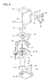
- the electromagnet relay includes a base 10, an electromagnet device 20, a contact mechanism 70, a card 80 and a box-shaped cover 90. Further, the card 80 is connected to the electromagnet device 20 and drives the contact mechanism 70.
- the base 10 has an approximately C-shaped insulation wall 11 which protrudes upward from an upper surface of the base 10 and is located at a center portion on the upper surface.
- the electromagnet device 20 described below is arranged on one side portion on the upper surface
- the contact mechanism 70 is arranged on the other side portion on the upper surface.
- the insulation wall 11 includes fitting grooves 12 which are formed in both inside surfaces, respectively which face each other. In the fitting grooves 12, both side edge portions of a yoke 50 are press-fitted.
- a center portion of an upper end of the insulation wall 11 is provided with a pair of guide ribs 13 that are in parallel with each other and protrude from an upper surface thereof.
- the electromagnet device 20 includes an electromagnet block 30 in which an iron core 40 having an almost T-shaped cross section extends through a central hole 33 of a spool 32 around which a coil 31 is wound, and an auxiliary yoke 45 is caulking-fixed to an upper end portion 41 of the iron core 40 which is passed through the central hole 33.
- the electromagnet device 20 further includes a yoke 50 having an almost L-shaped cross section which is assembled so that a permanent magnet 21 is interposed between the yoke 50 and an upper end face of the iron core 40, a support spring 55 attached to a rear surface of the yoke 50, and a movable iron piece 60 which is pivotably supported on a lower end face edge portion of the yoke 50 via the support spring 55.
- the lower end face edge portion of the yoke 50 serves as a fulcrum for pivoting the movable iron piece 60.
- spool 32 extended wires of the coil 31 are connected and soldered to coil terminals 35 which are press-fitted in corner portions of a guard portion 34.
- alignment protrusions 37 for aligning a position of the auxiliary yoke 45 are formed to protrude from an upper surface of an upper guard portion 36.
- the auxiliary yoke 45 has a caulking hole 46 in the center.
- connecting narrow-width portions 47 having a small cross-sectional area compared with a cross section of a base portion (a wide-width portion without including the caulking hole 46) of the auxiliary yoke 45, extends in parallel with each other from adjacent corner portions of the auxiliary yoke 45, respectively.
- the narrow width portions are magnetic resistance portions.
- the permanent magnet 21 has a width dimension substantially the same as a width dimension of the auxiliary yoke 45.
- the yoke 50 has an almost L-shaped cross section and includes a vertical portion 51 provided with notch portions 52 which are formed at both sides of the vertical portion 51, respectively.
- the notch portions 52 function to elastically engage the support spring 55 as described below.
- the yoke 50 further includes a horizontal portion 53 which laterally extends from an upper end of the vertical portion 51.
- a pair of elastic arm portions 56 extends in parallel with each other from both side edges of the support spring 55, respectively and an elastic support portion 59 extends from a lower edge portion of the support spring 55. While an engaging pawl 57 is formed to protrude from a leading end of either of the elastic arm portions56, a latching pawl 58 is formed to stand up from a leading end of the other elastic arm portion 56.
- a step portion 62 which is one step lower than other portions is formed in a front half portion on an upper surface of the horizontal portion 61, and a contact protrusion 63 is formed in the step portion 62 through a protruding process.
- the movable iron piece 60 has notch portions 65 for engaging the card 80 as described below, at both side edges of a leading end portion of the vertical portion 64 of the movable iron piece, respectively.
- the contact mechanism 70 includes first and second fixed touch pieces 71, 72 which are arranged to face each other at a predetermined distance, and a movable touch piece 73 arranged between the first and second fixed touch pieces 71 72.
- a movable contact 73a provided in the movable touch piece 73 which is arranged to be alternately attachable to and detachable from a first fixed contact 71a and a second fixed contact 72a.
- the first and the second fixed contact 71a, 72 are provided in the first and second fixed touch pieces 71, 72, respectively.
- Two sets of latching pawls 74, 75 for vertically latching a remaining end edge portion 83 of the card 80 described below are formed in an upper end portion of the movable touch piece 73 by a cutting process.
- a pair of elastic arm portions 82 and 82 extend from both sides of the contact protrusion 81, respectively that protrudes from one end, and a pair of latching arm portions 84 and 84 extend from both ends of the remaining end edge portion 83, respectively.
- the box-shaped cover 90 has a box shape which can fit into the base 10.
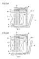
- the box-shaped cover 90 is provided with a position-regulating projecting portion 91 that bulges downward from the ceiling (refer to Fig. 7A and 7B ) thereof, and a degassing hole 92 provided in the bottom of the position-regulating projecting portion 91.
- the position-regulating projecting portion 91 prevents the card 80 aligned under the position-regulating projecting portion 91 from lifting.
- the box-shaped cover 90 has a marking recess 93 in an end portion of an upper surface thereof.
- the permanent magnet 21 may be interposed between the horizontal portion 53 of the yoke 50 and the auxiliary yoke 45 of the electromagnet block 30 and the movable iron piece 60 is aligned with the lower edge portion of the vertical portion 51 of the yoke 50. Further, the movable iron piece 60 is pivotably supported on the yoke 50 in such a manner that the engaging pawl 57 and the latching pawl 58 are engaged with and latched to the notch portions 52 of the yoke 50, respectively. Both side edge portions of the yoke 50 are press-fitted in the fitting grooves 12 provided in the inside surfaces of the insulation wall 11 of the base 10.
- the second fixed touch piece 72, the movable touch piece 73, and the first fixed touch piece 71 of the contact mechanism 70 are press-fitted in the other side in the upper surface of the base 10. Further, the other side in the upper surface is partitioned by the insulation wall 11. Subsequently, the contact protrusion 81 of the card 80 is brought into contact with the vicinity of an upper end portion of the movable iron piece 60, and the elastic arm portions 82 of the card 80 are engaged with the pair of engaging notch portions 65 provided in the vertical portion 64 of the movable iron piece 60, respectively. The latching pawls 74 and 75 of the movable touch piece 73 are latched to the remaining end edge portion 83 of the card 80.
- the box-shaped cover 90 is fitted into the base 10, and then sealed by injecting a sealing material which is not illustrated into the bottom of the base 10. Finally, gas inside the base is degassed through the degassing hole 92 of the box-shaped cover 90, and then the degassing hole 92 is subjected to heat caulking. Assembling work is thereby completed.
- a returned state of the movable iron piece 60 is maintained by balance between a spring force of the movable touch piece 73 and the magnetism generated by the magnetic flux which flows to the magnetic circuits M1 and M2.
- the auxiliary magnetic circuit M1 is in a magnetically saturated state.
- the vertical portion 64 of the movable iron piece 60 presses the movable touch piece 73 via the card 80, and the movable contact 73a separates from the first fixed contact 71a and comes into contact with the second fixed contact 72a ( Fig. 7B ).
- the movable iron piece in a moved state wherein an operation voltage is applied and movement is stopped, the movable iron piece is retained by a combined magnetic force of a magnetic flux flowing through the auxiliary magnetic circuit and a magnetic flux flowing through the main magnetic circuit. Accordingly, due to effective usage of the magnetic flux of the permanent magnet an electromagnet device having a strong retaining force to retain the movable iron piece in a moved state can be obtained. Further, there is an advantage that the magnetism of the permanent magnet is effectively used and thus a latching type electromagnetic relay with a strong retaining force for retaining the movable iron piece which is in a moved state can be obtained.
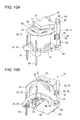
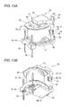
- FIG. 11 and 12 illustrates the differential features of the second embodiment such as a horizontal portion 53 of a yoke 50 is provided as a separate body, and an auxiliary yoke 45 provided with a connection narrow-width portion 47 which is a magnetic resistance portion of a smaller cross-sectional area than a base portion (a wide-width portion without including a caulking hole 46) and is integrally bent and raised from a center of an upper end portion of the yoke 50.
- a spool 32 and the yoke 50 are unified into a body by passing an iron core 40 through a central hole 33 of the spool 32 and by caulking-fixing an upper end portion 41 of the iron core 40 which is passed through to a caulking hole 46 of the auxiliary yoke 45.
- an auxiliary magnetic circuit M1 is formed as a structure in which a permanent magnet 21 is interposed between the auxiliary yoke 45 and a horizontal portion 53 where an end face of the horizontal portion 53 is in face contact with an area within an upper end portion of a vertical portion 51 of the yoke 50.
- the iron core 40 and the yoke 50 can be assembled with high assembling accuracy, and an electromagnet device 20 with a small variation in operating characteristic is obtainable. Further, since the magnetic flux of the permanent magnet also flows in the auxiliary magnetic circuit which is formed via the magnetic resistance portion with a small cross-sectional area of the auxiliary yoke, an electromagnet device which can easily maintain a returned state of the movable iron pieces as well as a moved state is obtained.
- FIG. 15 illustrates the differential features of the third embodiment such as unification is achieved by fitting a connection narrow-width portion 47 which is a magnetic resistance portion with a small cross-sectional area compared with a cross section of a base portion (a wide-width portion without including a caulking hole 46) of an auxiliary yoke 45 which extends sideways from a center of an end portion of the auxiliary yoke 45 into a fitting hole 54 provided in a vertical portion 51 of a yoke 50.
- a connection narrow-width portion 47 which is a magnetic resistance portion with a small cross-sectional area compared with a cross section of a base portion (a wide-width portion without including a caulking hole 46) of an auxiliary yoke 45 which extends sideways from a center of an end portion of the auxiliary yoke 45 into a fitting hole 54 provided in a vertical portion 51 of a yoke 50.
- the permanent magnet 21 can be interposed between a horizontal portion 53 of the yoke 50 and the auxiliary yoke 45 in advance by fitting the connection narrow-width portion 47 of the auxiliary yoke 45 which is caulking-fixed to an upper end portion 41 of an iron core 40 into the fitting hole 54 provided in the vertical portion 51 of yoke 50 for the purpose of unification. Accordingly, there is an advantage that assembling work becomes easy and work performance improves. Further, according to the present embodiment, alignment accuracy of the permanent magnet with respect to the auxiliary yoke as well as alignment accuracy of the auxiliary yoke improves, and an electromagnet device with a small variation in operating characteristic is obtained.
- An electromagnet device has a structure in which a permanent magnet 21 is interposed between a horizontal portion 53 extending from an end of a vertical portion 51 of a yoke 50 and an auxiliary yoke 45 joined to an upper end surface of the vertical portion 51 of the yoke 50, as schematically illustrated in Fig. 16 . And a connection narrow-width portion 53a which is a magnetic resistance portion having a small cross-sectional area compared with a cross section of a base portion is provided in the base portion of the horizontal portion 53 of the yoke 50. Because other portions are the same as those of the first embodiment, like portions are denoted by like reference signs and detailed description thereof is not given.
- the permanent magnet is interposed between the auxiliary yoke, and the horizontal portion of the yoke which is integrally formed through a cutting process so as to extend via the magnetic resistance portion with a small cross-sectional area, an electromagnet device which has a sufficient magnetic efficiency and leaks a small amount of the magnetic flux is obtained.
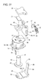
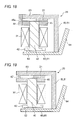
- a magnetic circuit may be formed according to a fifth embodiment as illustrated in Fig. 17 . That is, a permanent magnet is interposed between a horizontal portion 53 extending from an upper end of a vertical portion 51 of a yoke 50, and an auxiliary yoke 45 which is supported so that an end portion of the auxiliary yoke 45 is joined to an inside surface of an upper end portion of the vertical portion 51 of the yoke 50. And a connection narrow-width portion 53a which is a magnetic resistance portion having a small cross-sectional area compared with a cross section of a base portion is provided in the base portion of the horizontal portion 53 of the yoke 50.
- the auxiliary magnetic circuit where the magnetic flux of the permanent magnet is saturated is formed as a structure in which the horizontal portion of the yoke and the auxiliary yoke are connected to each other via the magnetic resistance portion with a small cross-sectional area. Accordingly, an electromagnet device which easily maintains the returned state of the movable iron piece is obtained.
- An auxiliary magnetic circuit M1 may be formed according to a sixth embodiment as illustrated in Fig. 18 .
- a permanent magnet 21 is interposed between a horizontal portion 53 of a yoke 50 and an auxiliary yoke 45 which is caulking-fixed to an iron core 40, the auxiliary yoke 45 and the horizontal portion 53 are connected to each other via a second auxiliary yoke 48 which has a connection narrow-width portion 48a, serving as a magnetic resistance portion with a small cross-sectional area compared with a cross section of a base portion of the auxiliary yoke 45.
- the auxiliary magnetic circuit is formed via the magnetic resistance portion with a small cross-sectional area which is provided in the one end portion of the iron core. Accordingly, the magnetic resistance portion with a small cross-sectional area needs not be provided in the yoke or the auxiliary yoke, and therefore a degree of freedom in design increases.
- an auxiliary yoke 45 extends from a leading end portion of a horizontal portion 53 of a yoke 50, via a connection narrow-width portion 47 which serves as a magnetic resistance portion with a small cross-sectional area compared with a cross section of a base portion of the auxiliary yoke 45.
- an auxiliary magnetic circuit M1 may be formed as a structure in which a permanent magnet 21 is interposed between the horizontal portion 53 of the yoke 50, and the auxiliary yoke 45 which is caulking-fixed to an iron core 40.
- the permanent magnet 21 is not necessarily a plate-like magnet, but may be an annular magnet as illustrated in Fig. 20 (an eighth embodiment).
- the permanent magnet 21 may be interposed between a horizontal portion 53 of a yoke 50 and an auxiliary yoke 45 in such a manner that an upper end portion 41 of an iron core 40 is inserted and passed through a through-hole of the auxiliary yoke and then the annular permanent magnet 22, and further caulking-fixed to a caulking hole 53b provided in the horizontal portion 53.
- the upper end portion 41 of the iron core 40 functions as a magnetic resistance portion with a small cross-sectional area compared with a cross section of a base portion of the iron core 40.
- a permanent magnet 21 may be interposed between a horizontal portion 53 of a yoke 50 and an auxiliary yoke 45 (a ninth embodiment).
- the auxiliary yoke 45 is not necessarily included. That is, an annular permanent magnet 22 through which an iron core 40 is passed may be interposed between a horizontal portion 53 of a yoke 50 and the iron core 40 having an upper end portion 41 which is caulking-fixed to a caulking hole 53b provided in a horizontal portion 53 (a tenth embodiment). According to the present embodiment, there is an advantage that an electromagnet device that can be produced with high productivity can be obtained because the number of parts and the number of assembling steps are decreased.
- the electromagnet device according to the present invention is applied not only to an electromagnetic relay but also to other electronic equipment.
Landscapes
- Physics & Mathematics (AREA)
- Electromagnetism (AREA)
- Engineering & Computer Science (AREA)
- Power Engineering (AREA)
- Electromagnets (AREA)
Applications Claiming Priority (1)
| Application Number | Priority Date | Filing Date | Title |
|---|---|---|---|
| JP2012185901A JP6171286B2 (ja) | 2012-08-24 | 2012-08-24 | 電磁石装置 |
Publications (3)
| Publication Number | Publication Date |
|---|---|
| EP2701164A2 true EP2701164A2 (de) | 2014-02-26 |
| EP2701164A3 EP2701164A3 (de) | 2014-09-10 |
| EP2701164B1 EP2701164B1 (de) | 2018-09-12 |
Family
ID=48877157
Family Applications (1)
| Application Number | Title | Priority Date | Filing Date |
|---|---|---|---|
| EP13178733.5A Active EP2701164B1 (de) | 2012-08-24 | 2013-07-31 | Elektromagnetvorrichtung |
Country Status (4)
| Country | Link |
|---|---|
| US (1) | US9153403B2 (de) |
| EP (1) | EP2701164B1 (de) |
| JP (1) | JP6171286B2 (de) |
| CN (1) | CN103632889B (de) |
Families Citing this family (3)
| Publication number | Priority date | Publication date | Assignee | Title |
|---|---|---|---|---|
| JP2016178124A (ja) * | 2015-03-18 | 2016-10-06 | オムロン株式会社 | 電磁石装置およびこれを備えた電磁継電器 |
| CN112885646B (zh) | 2021-01-15 | 2025-09-26 | 厦门宏发电力电器有限公司 | 一种拍合式双稳态磁路结构及磁保持继电器 |
| JP2024085497A (ja) * | 2022-12-15 | 2024-06-27 | オムロン株式会社 | 電磁石装置 |
Citations (1)
| Publication number | Priority date | Publication date | Assignee | Title |
|---|---|---|---|---|
| JPS58157947U (ja) | 1982-04-16 | 1983-10-21 | オムロン株式会社 | 磁気保持形リレ− |
Family Cites Families (26)
| Publication number | Priority date | Publication date | Assignee | Title |
|---|---|---|---|---|
| USRE24209E (en) | 1952-07-19 | 1956-09-04 | bernstein | |
| DE1035273B (de) | 1954-11-05 | 1958-07-31 | Siemens Ag | Schnell schaltendes Relais |
| DE1198455B (de) * | 1961-04-28 | 1965-08-12 | Siemens Ag | Elektromagnetisches Relais mit Haftcharakteristik |
| US3599133A (en) * | 1970-03-10 | 1971-08-10 | Amf Inc | Latch relay motor structure |
| BE786006A (fr) * | 1971-07-07 | 1973-01-08 | Siemens Ag | Circuit magnetique de relais polarise |
| JPS49103941U (de) * | 1972-12-27 | 1974-09-06 | ||
| JPS5063550U (de) * | 1973-10-13 | 1975-06-10 | ||
| DE2503159C3 (de) * | 1975-01-27 | 1981-05-07 | Siemens AG, 1000 Berlin und 8000 München | Polarisiertes elektromagnetisches Relais und Verfahren zu dessen Herstellung |
| US4339734A (en) * | 1980-02-04 | 1982-07-13 | International Standard Electric Corporation | Encased miniature relay |
| JPS5816428A (ja) * | 1981-07-22 | 1983-01-31 | 松下電工株式会社 | ラツチング型リレ− |
| DE3140374A1 (de) | 1981-10-10 | 1983-04-28 | Eberle Anlagen KG, 8500 Nürnberg | Bistabiles klappankerrelais |
| DE3332487C2 (de) * | 1983-04-09 | 1993-11-18 | Original Electric Mfg & Co Ltd | Elektromagnetisches Relais |
| DE3438275C1 (de) | 1984-10-18 | 1989-11-23 | SDS-Relais AG, 8024 Deisenhofen | Gepoltes elektromagnetisches Relais |
| US4728917A (en) * | 1986-01-16 | 1988-03-01 | Siemens Aktiengesellschaft | Electromagnetic relay wherein response voltage is rendered temperature independent |
| JPH0246707A (ja) * | 1988-08-08 | 1990-02-16 | Mic Kogyo Kk | 電磁石 |
| JPH04277430A (ja) * | 1991-03-06 | 1992-10-02 | Nec Corp | 電磁リレー |
| AT414183B (de) * | 1994-06-08 | 2006-10-15 | Tyco Electronics Austria Gmbh | Bistabile schaltvorrichtung |
| JPH0845407A (ja) * | 1994-08-02 | 1996-02-16 | Niles Parts Co Ltd | 電磁継電器の構造 |
| JPH08180785A (ja) * | 1994-12-26 | 1996-07-12 | Nippondenso Co Ltd | 電磁継電器 |
| DE19641407C1 (de) * | 1996-10-08 | 1998-01-15 | Eh Schrack Components Ag | Bistabiles Elektromagnetsystem für ein Relais |
| JP2002343213A (ja) * | 2001-05-18 | 2002-11-29 | Daiichi Denki Kk | 小型継電器 |
| JP4168733B2 (ja) * | 2002-11-12 | 2008-10-22 | オムロン株式会社 | 電磁継電器 |
| JP2005166431A (ja) * | 2003-12-02 | 2005-06-23 | Omron Corp | 電磁継電器 |
| JP5142652B2 (ja) * | 2007-01-31 | 2013-02-13 | 富士通コンポーネント株式会社 | 有極電磁継電器及びコイル組立 |
| JP5427492B2 (ja) * | 2009-07-02 | 2014-02-26 | 富士通コンポーネント株式会社 | 電磁継電器 |
| CN102103942B (zh) * | 2009-12-17 | 2013-06-05 | 厦门宏发电声股份有限公司 | 一种继电器的衔铁与推动机构之间的连接结构 |
-
2012
- 2012-08-24 JP JP2012185901A patent/JP6171286B2/ja active Active
-
2013
- 2013-07-29 CN CN201310322642.9A patent/CN103632889B/zh active Active
- 2013-07-30 US US13/953,995 patent/US9153403B2/en active Active
- 2013-07-31 EP EP13178733.5A patent/EP2701164B1/de active Active
Patent Citations (1)
| Publication number | Priority date | Publication date | Assignee | Title |
|---|---|---|---|---|
| JPS58157947U (ja) | 1982-04-16 | 1983-10-21 | オムロン株式会社 | 磁気保持形リレ− |
Also Published As
| Publication number | Publication date |
|---|---|
| CN103632889B (zh) | 2016-10-12 |
| EP2701164A3 (de) | 2014-09-10 |
| CN103632889A (zh) | 2014-03-12 |
| EP2701164B1 (de) | 2018-09-12 |
| JP2014044840A (ja) | 2014-03-13 |
| JP6171286B2 (ja) | 2017-08-02 |
| US9153403B2 (en) | 2015-10-06 |
| US20140055220A1 (en) | 2014-02-27 |
Similar Documents
| Publication | Publication Date | Title |
|---|---|---|
| EP2701172B1 (de) | Elektromagnetvorrichtung, Montageverfahren dafür und elektromagnetisches Relais damit | |
| US9136080B2 (en) | Electromagnet device and electromagnetic relay using the same | |
| US11120961B2 (en) | Electromagnetic relay and coil terminal | |
| JP6897499B2 (ja) | 電磁継電器 | |
| US9324524B2 (en) | Electromagnetic relay | |
| US9748065B2 (en) | Sealed contact device | |
| US20090322454A1 (en) | Electromagnetic relay | |
| JP2011192469A (ja) | 接点開閉構造及び電磁リレー | |
| JP2015035403A (ja) | 接点機構およびこれを用いた電磁継電器 | |
| CN203192704U (zh) | 电磁铁装置及使用其的电磁继电器 | |
| US9153403B2 (en) | Electromagnet device | |
| JP2014044837A5 (de) | ||
| US8963660B2 (en) | Electromagnetic relay | |
| CN101872696A (zh) | 电磁接触器 | |
| JP5549642B2 (ja) | 継電器 | |
| CN201946510U (zh) | 一种电磁继电器外壳与底板卡接结构 | |
| CN202585274U (zh) | 一种电磁继电器用动簧片 | |
| EP2768000B1 (de) | Elektromagnetische Schaltvorrichtung | |
| CN201946512U (zh) | 一种电磁继电器外壳内卡扣结构 | |
| JP4742790B2 (ja) | 電磁石装置および電磁リレー | |
| CN116504586A (zh) | 一种动簧片以及包括该动簧片的继电器 | |
| CN121768910A (zh) | 一种双磁钢继电器 |
Legal Events
| Date | Code | Title | Description |
|---|---|---|---|
| PUAI | Public reference made under article 153(3) epc to a published international application that has entered the european phase |
Free format text: ORIGINAL CODE: 0009012 |
|
| AK | Designated contracting states |
Kind code of ref document: A2 Designated state(s): AL AT BE BG CH CY CZ DE DK EE ES FI FR GB GR HR HU IE IS IT LI LT LU LV MC MK MT NL NO PL PT RO RS SE SI SK SM TR |
|
| AX | Request for extension of the european patent |
Extension state: BA ME |
|
| PUAL | Search report despatched |
Free format text: ORIGINAL CODE: 0009013 |
|
| AK | Designated contracting states |
Kind code of ref document: A3 Designated state(s): AL AT BE BG CH CY CZ DE DK EE ES FI FR GB GR HR HU IE IS IT LI LT LU LV MC MK MT NL NO PL PT RO RS SE SI SK SM TR |
|
| AX | Request for extension of the european patent |
Extension state: BA ME |
|
| RIC1 | Information provided on ipc code assigned before grant |
Ipc: H01F 7/16 20060101AFI20140805BHEP |
|
| 17P | Request for examination filed |
Effective date: 20150310 |
|
| RBV | Designated contracting states (corrected) |
Designated state(s): AL AT BE BG CH CY CZ DE DK EE ES FI FR GB GR HR HU IE IS IT LI LT LU LV MC MK MT NL NO PL PT RO RS SE SI SK SM TR |
|
| STAA | Information on the status of an ep patent application or granted ep patent |
Free format text: STATUS: EXAMINATION IS IN PROGRESS |
|
| 17Q | First examination report despatched |
Effective date: 20170904 |
|
| GRAP | Despatch of communication of intention to grant a patent |
Free format text: ORIGINAL CODE: EPIDOSNIGR1 |
|
| STAA | Information on the status of an ep patent application or granted ep patent |
Free format text: STATUS: GRANT OF PATENT IS INTENDED |
|
| INTG | Intention to grant announced |
Effective date: 20180323 |
|
| GRAS | Grant fee paid |
Free format text: ORIGINAL CODE: EPIDOSNIGR3 |
|
| GRAA | (expected) grant |
Free format text: ORIGINAL CODE: 0009210 |
|
| STAA | Information on the status of an ep patent application or granted ep patent |
Free format text: STATUS: THE PATENT HAS BEEN GRANTED |
|
| AK | Designated contracting states |
Kind code of ref document: B1 Designated state(s): AL AT BE BG CH CY CZ DE DK EE ES FI FR GB GR HR HU IE IS IT LI LT LU LV MC MK MT NL NO PL PT RO RS SE SI SK SM TR |
|
| REG | Reference to a national code |
Ref country code: GB Ref legal event code: FG4D |
|
| REG | Reference to a national code |
Ref country code: CH Ref legal event code: EP |
|
| REG | Reference to a national code |
Ref country code: IE Ref legal event code: FG4D |
|
| REG | Reference to a national code |
Ref country code: DE Ref legal event code: R096 Ref document number: 602013043466 Country of ref document: DE |
|
| REG | Reference to a national code |
Ref country code: AT Ref legal event code: REF Ref document number: 1041553 Country of ref document: AT Kind code of ref document: T Effective date: 20181015 |
|
| REG | Reference to a national code |
Ref country code: NL Ref legal event code: MP Effective date: 20180912 |
|
| REG | Reference to a national code |
Ref country code: LT Ref legal event code: MG4D |
|
| PG25 | Lapsed in a contracting state [announced via postgrant information from national office to epo] |
Ref country code: NO Free format text: LAPSE BECAUSE OF FAILURE TO SUBMIT A TRANSLATION OF THE DESCRIPTION OR TO PAY THE FEE WITHIN THE PRESCRIBED TIME-LIMIT Effective date: 20181212 Ref country code: BG Free format text: LAPSE BECAUSE OF FAILURE TO SUBMIT A TRANSLATION OF THE DESCRIPTION OR TO PAY THE FEE WITHIN THE PRESCRIBED TIME-LIMIT Effective date: 20181212 Ref country code: LT Free format text: LAPSE BECAUSE OF FAILURE TO SUBMIT A TRANSLATION OF THE DESCRIPTION OR TO PAY THE FEE WITHIN THE PRESCRIBED TIME-LIMIT Effective date: 20180912 Ref country code: RS Free format text: LAPSE BECAUSE OF FAILURE TO SUBMIT A TRANSLATION OF THE DESCRIPTION OR TO PAY THE FEE WITHIN THE PRESCRIBED TIME-LIMIT Effective date: 20180912 Ref country code: GR Free format text: LAPSE BECAUSE OF FAILURE TO SUBMIT A TRANSLATION OF THE DESCRIPTION OR TO PAY THE FEE WITHIN THE PRESCRIBED TIME-LIMIT Effective date: 20181213 Ref country code: FI Free format text: LAPSE BECAUSE OF FAILURE TO SUBMIT A TRANSLATION OF THE DESCRIPTION OR TO PAY THE FEE WITHIN THE PRESCRIBED TIME-LIMIT Effective date: 20180912 Ref country code: SE Free format text: LAPSE BECAUSE OF FAILURE TO SUBMIT A TRANSLATION OF THE DESCRIPTION OR TO PAY THE FEE WITHIN THE PRESCRIBED TIME-LIMIT Effective date: 20180912 |
|
| PG25 | Lapsed in a contracting state [announced via postgrant information from national office to epo] |
Ref country code: AL Free format text: LAPSE BECAUSE OF FAILURE TO SUBMIT A TRANSLATION OF THE DESCRIPTION OR TO PAY THE FEE WITHIN THE PRESCRIBED TIME-LIMIT Effective date: 20180912 Ref country code: HR Free format text: LAPSE BECAUSE OF FAILURE TO SUBMIT A TRANSLATION OF THE DESCRIPTION OR TO PAY THE FEE WITHIN THE PRESCRIBED TIME-LIMIT Effective date: 20180912 Ref country code: LV Free format text: LAPSE BECAUSE OF FAILURE TO SUBMIT A TRANSLATION OF THE DESCRIPTION OR TO PAY THE FEE WITHIN THE PRESCRIBED TIME-LIMIT Effective date: 20180912 |
|
| REG | Reference to a national code |
Ref country code: AT Ref legal event code: MK05 Ref document number: 1041553 Country of ref document: AT Kind code of ref document: T Effective date: 20180912 |
|
| PG25 | Lapsed in a contracting state [announced via postgrant information from national office to epo] |
Ref country code: NL Free format text: LAPSE BECAUSE OF FAILURE TO SUBMIT A TRANSLATION OF THE DESCRIPTION OR TO PAY THE FEE WITHIN THE PRESCRIBED TIME-LIMIT Effective date: 20180912 Ref country code: AT Free format text: LAPSE BECAUSE OF FAILURE TO SUBMIT A TRANSLATION OF THE DESCRIPTION OR TO PAY THE FEE WITHIN THE PRESCRIBED TIME-LIMIT Effective date: 20180912 Ref country code: EE Free format text: LAPSE BECAUSE OF FAILURE TO SUBMIT A TRANSLATION OF THE DESCRIPTION OR TO PAY THE FEE WITHIN THE PRESCRIBED TIME-LIMIT Effective date: 20180912 Ref country code: IS Free format text: LAPSE BECAUSE OF FAILURE TO SUBMIT A TRANSLATION OF THE DESCRIPTION OR TO PAY THE FEE WITHIN THE PRESCRIBED TIME-LIMIT Effective date: 20190112 Ref country code: PL Free format text: LAPSE BECAUSE OF FAILURE TO SUBMIT A TRANSLATION OF THE DESCRIPTION OR TO PAY THE FEE WITHIN THE PRESCRIBED TIME-LIMIT Effective date: 20180912 Ref country code: IT Free format text: LAPSE BECAUSE OF FAILURE TO SUBMIT A TRANSLATION OF THE DESCRIPTION OR TO PAY THE FEE WITHIN THE PRESCRIBED TIME-LIMIT Effective date: 20180912 Ref country code: ES Free format text: LAPSE BECAUSE OF FAILURE TO SUBMIT A TRANSLATION OF THE DESCRIPTION OR TO PAY THE FEE WITHIN THE PRESCRIBED TIME-LIMIT Effective date: 20180912 Ref country code: CZ Free format text: LAPSE BECAUSE OF FAILURE TO SUBMIT A TRANSLATION OF THE DESCRIPTION OR TO PAY THE FEE WITHIN THE PRESCRIBED TIME-LIMIT Effective date: 20180912 Ref country code: RO Free format text: LAPSE BECAUSE OF FAILURE TO SUBMIT A TRANSLATION OF THE DESCRIPTION OR TO PAY THE FEE WITHIN THE PRESCRIBED TIME-LIMIT Effective date: 20180912 |
|
| PG25 | Lapsed in a contracting state [announced via postgrant information from national office to epo] |
Ref country code: SM Free format text: LAPSE BECAUSE OF FAILURE TO SUBMIT A TRANSLATION OF THE DESCRIPTION OR TO PAY THE FEE WITHIN THE PRESCRIBED TIME-LIMIT Effective date: 20180912 Ref country code: PT Free format text: LAPSE BECAUSE OF FAILURE TO SUBMIT A TRANSLATION OF THE DESCRIPTION OR TO PAY THE FEE WITHIN THE PRESCRIBED TIME-LIMIT Effective date: 20190112 Ref country code: SK Free format text: LAPSE BECAUSE OF FAILURE TO SUBMIT A TRANSLATION OF THE DESCRIPTION OR TO PAY THE FEE WITHIN THE PRESCRIBED TIME-LIMIT Effective date: 20180912 |
|
| REG | Reference to a national code |
Ref country code: DE Ref legal event code: R097 Ref document number: 602013043466 Country of ref document: DE |
|
| PLBE | No opposition filed within time limit |
Free format text: ORIGINAL CODE: 0009261 |
|
| STAA | Information on the status of an ep patent application or granted ep patent |
Free format text: STATUS: NO OPPOSITION FILED WITHIN TIME LIMIT |
|
| PG25 | Lapsed in a contracting state [announced via postgrant information from national office to epo] |
Ref country code: DK Free format text: LAPSE BECAUSE OF FAILURE TO SUBMIT A TRANSLATION OF THE DESCRIPTION OR TO PAY THE FEE WITHIN THE PRESCRIBED TIME-LIMIT Effective date: 20180912 |
|
| 26N | No opposition filed |
Effective date: 20190613 |
|
| PG25 | Lapsed in a contracting state [announced via postgrant information from national office to epo] |
Ref country code: SI Free format text: LAPSE BECAUSE OF FAILURE TO SUBMIT A TRANSLATION OF THE DESCRIPTION OR TO PAY THE FEE WITHIN THE PRESCRIBED TIME-LIMIT Effective date: 20180912 |
|
| PG25 | Lapsed in a contracting state [announced via postgrant information from national office to epo] |
Ref country code: MC Free format text: LAPSE BECAUSE OF FAILURE TO SUBMIT A TRANSLATION OF THE DESCRIPTION OR TO PAY THE FEE WITHIN THE PRESCRIBED TIME-LIMIT Effective date: 20180912 |
|
| REG | Reference to a national code |
Ref country code: CH Ref legal event code: PL |
|
| GBPC | Gb: european patent ceased through non-payment of renewal fee |
Effective date: 20190731 |
|
| PG25 | Lapsed in a contracting state [announced via postgrant information from national office to epo] |
Ref country code: TR Free format text: LAPSE BECAUSE OF FAILURE TO SUBMIT A TRANSLATION OF THE DESCRIPTION OR TO PAY THE FEE WITHIN THE PRESCRIBED TIME-LIMIT Effective date: 20180912 |
|
| REG | Reference to a national code |
Ref country code: BE Ref legal event code: MM Effective date: 20190731 |
|
| PG25 | Lapsed in a contracting state [announced via postgrant information from national office to epo] |
Ref country code: GB Free format text: LAPSE BECAUSE OF NON-PAYMENT OF DUE FEES Effective date: 20190731 |
|
| PG25 | Lapsed in a contracting state [announced via postgrant information from national office to epo] |
Ref country code: LU Free format text: LAPSE BECAUSE OF NON-PAYMENT OF DUE FEES Effective date: 20190731 Ref country code: CH Free format text: LAPSE BECAUSE OF NON-PAYMENT OF DUE FEES Effective date: 20190731 Ref country code: LI Free format text: LAPSE BECAUSE OF NON-PAYMENT OF DUE FEES Effective date: 20190731 Ref country code: BE Free format text: LAPSE BECAUSE OF NON-PAYMENT OF DUE FEES Effective date: 20190731 |
|
| PG25 | Lapsed in a contracting state [announced via postgrant information from national office to epo] |
Ref country code: FR Free format text: LAPSE BECAUSE OF NON-PAYMENT OF DUE FEES Effective date: 20190731 |
|
| PG25 | Lapsed in a contracting state [announced via postgrant information from national office to epo] |
Ref country code: IE Free format text: LAPSE BECAUSE OF NON-PAYMENT OF DUE FEES Effective date: 20190731 |
|
| PG25 | Lapsed in a contracting state [announced via postgrant information from national office to epo] |
Ref country code: CY Free format text: LAPSE BECAUSE OF FAILURE TO SUBMIT A TRANSLATION OF THE DESCRIPTION OR TO PAY THE FEE WITHIN THE PRESCRIBED TIME-LIMIT Effective date: 20180912 |
|
| PG25 | Lapsed in a contracting state [announced via postgrant information from national office to epo] |
Ref country code: MT Free format text: LAPSE BECAUSE OF FAILURE TO SUBMIT A TRANSLATION OF THE DESCRIPTION OR TO PAY THE FEE WITHIN THE PRESCRIBED TIME-LIMIT Effective date: 20180912 Ref country code: HU Free format text: LAPSE BECAUSE OF FAILURE TO SUBMIT A TRANSLATION OF THE DESCRIPTION OR TO PAY THE FEE WITHIN THE PRESCRIBED TIME-LIMIT; INVALID AB INITIO Effective date: 20130731 |
|
| PG25 | Lapsed in a contracting state [announced via postgrant information from national office to epo] |
Ref country code: MK Free format text: LAPSE BECAUSE OF FAILURE TO SUBMIT A TRANSLATION OF THE DESCRIPTION OR TO PAY THE FEE WITHIN THE PRESCRIBED TIME-LIMIT Effective date: 20180912 |
|
| PGFP | Annual fee paid to national office [announced via postgrant information from national office to epo] |
Ref country code: DE Payment date: 20250722 Year of fee payment: 13 |