EP2701252A1 - Vorrichtung für elektrische entladung - Google Patents
Vorrichtung für elektrische entladung Download PDFInfo
- Publication number
- EP2701252A1 EP2701252A1 EP12864678.3A EP12864678A EP2701252A1 EP 2701252 A1 EP2701252 A1 EP 2701252A1 EP 12864678 A EP12864678 A EP 12864678A EP 2701252 A1 EP2701252 A1 EP 2701252A1
- Authority
- EP
- European Patent Office
- Prior art keywords
- discharge
- tube
- discharge member
- counter electrode
- discharge device
- Prior art date
- Legal status (The legal status is an assumption and is not a legal conclusion. Google has not performed a legal analysis and makes no representation as to the accuracy of the status listed.)
- Granted
Links
Images



Classifications
-
- F—MECHANICAL ENGINEERING; LIGHTING; HEATING; WEAPONS; BLASTING
- F24—HEATING; RANGES; VENTILATING
- F24F—AIR-CONDITIONING; AIR-HUMIDIFICATION; VENTILATION; USE OF AIR CURRENTS FOR SCREENING
- F24F1/00—Room units for air-conditioning, e.g. separate or self-contained units or units receiving primary air from a central station
- F24F1/0007—Indoor units, e.g. fan coil units
- F24F1/0071—Indoor units, e.g. fan coil units with means for purifying supplied air
- F24F1/0073—Indoor units, e.g. fan coil units with means for purifying supplied air characterised by the mounting or arrangement of filters
-
- A—HUMAN NECESSITIES
- A61—MEDICAL OR VETERINARY SCIENCE; HYGIENE
- A61L—METHODS OR APPARATUS FOR STERILISING MATERIALS OR OBJECTS IN GENERAL; DISINFECTION, STERILISATION OR DEODORISATION OF AIR; CHEMICAL ASPECTS OF BANDAGES, DRESSINGS, ABSORBENT PADS OR SURGICAL ARTICLES; MATERIALS FOR BANDAGES, DRESSINGS, ABSORBENT PADS OR SURGICAL ARTICLES
- A61L9/00—Disinfection, sterilisation or deodorisation of air
- A61L9/16—Disinfection, sterilisation or deodorisation of air using physical phenomena
- A61L9/22—Ionisation
-
- B—PERFORMING OPERATIONS; TRANSPORTING
- B03—SEPARATION OF SOLID MATERIALS USING LIQUIDS OR USING PNEUMATIC TABLES OR JIGS; MAGNETIC OR ELECTROSTATIC SEPARATION OF SOLID MATERIALS FROM SOLID MATERIALS OR FLUIDS; SEPARATION BY HIGH-VOLTAGE ELECTRIC FIELDS
- B03C—MAGNETIC OR ELECTROSTATIC SEPARATION OF SOLID MATERIALS FROM SOLID MATERIALS OR FLUIDS; SEPARATION BY HIGH-VOLTAGE ELECTRIC FIELDS
- B03C3/00—Separating dispersed particles from gases or vapour, e.g. air, by electrostatic effect
- B03C3/02—Plant or installations having external electricity supply
- B03C3/04—Plant or installations having external electricity supply dry type
- B03C3/09—Plant or installations having external electricity supply dry type characterised by presence of stationary flat electrodes arranged with their flat surfaces at right angles to the gas stream
-
- B—PERFORMING OPERATIONS; TRANSPORTING
- B03—SEPARATION OF SOLID MATERIALS USING LIQUIDS OR USING PNEUMATIC TABLES OR JIGS; MAGNETIC OR ELECTROSTATIC SEPARATION OF SOLID MATERIALS FROM SOLID MATERIALS OR FLUIDS; SEPARATION BY HIGH-VOLTAGE ELECTRIC FIELDS
- B03C—MAGNETIC OR ELECTROSTATIC SEPARATION OF SOLID MATERIALS FROM SOLID MATERIALS OR FLUIDS; SEPARATION BY HIGH-VOLTAGE ELECTRIC FIELDS
- B03C3/00—Separating dispersed particles from gases or vapour, e.g. air, by electrostatic effect
- B03C3/02—Plant or installations having external electricity supply
- B03C3/04—Plant or installations having external electricity supply dry type
- B03C3/12—Plant or installations having external electricity supply dry type characterised by separation of ionising and collecting stations
-
- B—PERFORMING OPERATIONS; TRANSPORTING
- B03—SEPARATION OF SOLID MATERIALS USING LIQUIDS OR USING PNEUMATIC TABLES OR JIGS; MAGNETIC OR ELECTROSTATIC SEPARATION OF SOLID MATERIALS FROM SOLID MATERIALS OR FLUIDS; SEPARATION BY HIGH-VOLTAGE ELECTRIC FIELDS
- B03C—MAGNETIC OR ELECTROSTATIC SEPARATION OF SOLID MATERIALS FROM SOLID MATERIALS OR FLUIDS; SEPARATION BY HIGH-VOLTAGE ELECTRIC FIELDS
- B03C3/00—Separating dispersed particles from gases or vapour, e.g. air, by electrostatic effect
- B03C3/34—Constructional details or accessories or operation thereof
- B03C3/38—Particle charging or ionising stations, e.g. using electric discharge, radioactive radiation or flames
-
- B—PERFORMING OPERATIONS; TRANSPORTING
- B03—SEPARATION OF SOLID MATERIALS USING LIQUIDS OR USING PNEUMATIC TABLES OR JIGS; MAGNETIC OR ELECTROSTATIC SEPARATION OF SOLID MATERIALS FROM SOLID MATERIALS OR FLUIDS; SEPARATION BY HIGH-VOLTAGE ELECTRIC FIELDS
- B03C—MAGNETIC OR ELECTROSTATIC SEPARATION OF SOLID MATERIALS FROM SOLID MATERIALS OR FLUIDS; SEPARATION BY HIGH-VOLTAGE ELECTRIC FIELDS
- B03C3/00—Separating dispersed particles from gases or vapour, e.g. air, by electrostatic effect
- B03C3/34—Constructional details or accessories or operation thereof
- B03C3/40—Electrode constructions
- B03C3/41—Ionising-electrodes
-
- B—PERFORMING OPERATIONS; TRANSPORTING
- B03—SEPARATION OF SOLID MATERIALS USING LIQUIDS OR USING PNEUMATIC TABLES OR JIGS; MAGNETIC OR ELECTROSTATIC SEPARATION OF SOLID MATERIALS FROM SOLID MATERIALS OR FLUIDS; SEPARATION BY HIGH-VOLTAGE ELECTRIC FIELDS
- B03C—MAGNETIC OR ELECTROSTATIC SEPARATION OF SOLID MATERIALS FROM SOLID MATERIALS OR FLUIDS; SEPARATION BY HIGH-VOLTAGE ELECTRIC FIELDS
- B03C3/00—Separating dispersed particles from gases or vapour, e.g. air, by electrostatic effect
- B03C3/34—Constructional details or accessories or operation thereof
- B03C3/40—Electrode constructions
- B03C3/45—Collecting-electrodes
- B03C3/47—Collecting-electrodes flat, e.g. plates, discs, gratings
-
- F—MECHANICAL ENGINEERING; LIGHTING; HEATING; WEAPONS; BLASTING
- F24—HEATING; RANGES; VENTILATING
- F24F—AIR-CONDITIONING; AIR-HUMIDIFICATION; VENTILATION; USE OF AIR CURRENTS FOR SCREENING
- F24F1/00—Room units for air-conditioning, e.g. separate or self-contained units or units receiving primary air from a central station
- F24F1/0007—Indoor units, e.g. fan coil units
- F24F1/0071—Indoor units, e.g. fan coil units with means for purifying supplied air
- F24F1/0076—Indoor units, e.g. fan coil units with means for purifying supplied air by electric means, e.g. ionisers or electrostatic separators
-
- H—ELECTRICITY
- H01—ELECTRIC ELEMENTS
- H01T—SPARK GAPS; OVERVOLTAGE ARRESTERS USING SPARK GAPS; SPARKING PLUGS; CORONA DEVICES; GENERATING IONS TO BE INTRODUCED INTO NON-ENCLOSED GASES
- H01T19/00—Devices providing for corona discharge
-
- H—ELECTRICITY
- H01—ELECTRIC ELEMENTS
- H01T—SPARK GAPS; OVERVOLTAGE ARRESTERS USING SPARK GAPS; SPARKING PLUGS; CORONA DEVICES; GENERATING IONS TO BE INTRODUCED INTO NON-ENCLOSED GASES
- H01T23/00—Apparatus for generating ions to be introduced into non-enclosed gases, e.g. into the atmosphere
-
- H—ELECTRICITY
- H05—ELECTRIC TECHNIQUES NOT OTHERWISE PROVIDED FOR
- H05H—PLASMA TECHNIQUE; PRODUCTION OF ACCELERATED ELECTRICALLY-CHARGED PARTICLES OR OF NEUTRONS; PRODUCTION OR ACCELERATION OF NEUTRAL MOLECULAR OR ATOMIC BEAMS
- H05H1/00—Generating plasma; Handling plasma
- H05H1/24—Generating plasma
- H05H1/47—Generating plasma using corona discharges
-
- B—PERFORMING OPERATIONS; TRANSPORTING
- B03—SEPARATION OF SOLID MATERIALS USING LIQUIDS OR USING PNEUMATIC TABLES OR JIGS; MAGNETIC OR ELECTROSTATIC SEPARATION OF SOLID MATERIALS FROM SOLID MATERIALS OR FLUIDS; SEPARATION BY HIGH-VOLTAGE ELECTRIC FIELDS
- B03C—MAGNETIC OR ELECTROSTATIC SEPARATION OF SOLID MATERIALS FROM SOLID MATERIALS OR FLUIDS; SEPARATION BY HIGH-VOLTAGE ELECTRIC FIELDS
- B03C2201/00—Details of magnetic or electrostatic separation
- B03C2201/04—Ionising electrode being a wire
-
- F—MECHANICAL ENGINEERING; LIGHTING; HEATING; WEAPONS; BLASTING
- F24—HEATING; RANGES; VENTILATING
- F24F—AIR-CONDITIONING; AIR-HUMIDIFICATION; VENTILATION; USE OF AIR CURRENTS FOR SCREENING
- F24F1/00—Room units for air-conditioning, e.g. separate or self-contained units or units receiving primary air from a central station
- F24F1/0007—Indoor units, e.g. fan coil units
- F24F1/0043—Indoor units, e.g. fan coil units characterised by mounting arrangements
- F24F1/0057—Indoor units, e.g. fan coil units characterised by mounting arrangements mounted in or on a wall
-
- H—ELECTRICITY
- H05—ELECTRIC TECHNIQUES NOT OTHERWISE PROVIDED FOR
- H05H—PLASMA TECHNIQUE; PRODUCTION OF ACCELERATED ELECTRICALLY-CHARGED PARTICLES OR OF NEUTRONS; PRODUCTION OR ACCELERATION OF NEUTRAL MOLECULAR OR ATOMIC BEAMS
- H05H2245/00—Applications of plasma devices
- H05H2245/30—Medical applications
- H05H2245/36—Sterilisation of objects, liquids, volumes or surfaces
Definitions
- the present invention relates to a discharge device.
- An electric precipitator including an ionized wire formed by swaging crimping terminals at opposite ends of a discharge member.
- the electric precipitator allows a loop portion of the crimping terminal to be easily hung on a spring (for example, see Patent Literature 1).
- an air cleaner in which a metal pipe is crimped to loop portions formed by bending opposite ends of a discharge member.
- a crimp portion between the end of the discharge member and the metal pipe is covered with an electrically insulating resin pipe. This can prevent the discharge member from being cut at the end of the metal pipe (for example, see Patent Literature 2).
- the present invention is made to solve the above described problems, and aims to provide a discharge device that can prevent cutting of a discharge member, and allows both a reduction in thickness and an improvement in assemblability.
- a discharge device of the present invention includes a discharge electrode and a counter electrode facing each other, wherein the discharge electrode includes a discharge member facing the counter electrode, a loop-like terminal mounted to an end of the discharge member in a longitudinal direction, and a tube having an electrically insulating property and covering a mounting portion between an end of the discharge member and the terminal.
- the present invention can prevent cutting of a discharge member, and allows both a reduction in thickness and an improvement in assemblability.
- Figure 1 is an exploded perspective view of a discharge device in Embodiment 1 of the present invention.
- a positive side of a Z axis in Figure 1 is a windward side.
- a negative side of the Z axis in Figure 1 is a leeward side.
- an outline of the discharge device is formed of an upper frame 1 and a lower frame 2.
- the upper frame 1 is placed on the most windward side of the discharge device.
- the upper frame 1 is entirely made of resin.
- the upper frame 1 includes a lattice.
- the lattice is formed to prevent a human's finger from entering the discharge device.
- Each hole partitioned by the lattice is an opening portion.
- the opening portion is formed so as to take air outside the discharge device into the discharge device.
- the opening portion is formed in an upper surface (a surface parallel to an X-Y plane in Figure 1 ) of the upper frame 1 over a predetermined width (a distance in an X axis direction in Figure 1 ) and a predetermined depth (a distance in a Y axis direction in Figure 1 ).
- a handle is provided in the upper frame 1. The handle is formed so as to be gripped by a human when holding the discharge device by hand.
- the lower frame 2 is placed on the most leeward side of the discharge device.
- the lower frame 2 is entirely made of resin.
- the lower frame 2 includes a lattice.
- the lattice is formed to prevent a human's finger from entering the discharge device.
- Each hole partitioned by the lattice is an opening portion.
- the opening portion is formed so as to discharge air taken into the discharge device to the outside of the discharge device.
- the opening portion is formed in a lower surface (a surface parallel to the X-Y plane in Figure 1 ) of the lower frame 2 over a predetermined width (a distance in the X axis direction in Figure 1 ) and a predetermined depth (a distance in the Y axis direction in Figure 1 ).
- each opening portion in the lower frame 2 having the opening portion faces each opening portion in the upper frame 1 at a predetermined distance in a height direction (a Z axis direction in Figure 1 ).
- a prefilter 3 is fitted in a front surface of the upper frame 1.
- the prefilter 3 is formed of mesh finer than the lattice of the opening surface of the upper frame 1.
- the discharge device includes therein a counter electrode 4, a first electrode support unit 5, a second electrode support unit 6, a power feeding unit 7, a discharge electrode 8, and a spring 9.
- the counter electrode 4 is placed to face the lower frame 2.
- the first electrode support unit 5 is entirely made of resin.
- the first electrode support unit 5 secures the end of one side on the counter electrode 4.
- the second electrode support unit 6 is entirely made of resin.
- the second electrode support unit 6 secures the other end of the counter electrode 4.
- the power feeding unit 7 is made of metal.
- the power feeding unit 7 is mounted to the other end of the lower frame 2 so as not to interfere with the second electrode support unit 6.
- the discharge electrode 8 is held in a proper position, with an intermediate portion being folded back about twice to four times, by a member of the first electrode support unit 5 and a member of the second electrode support unit 6.
- the spring 9 is made of metal.
- the spring 9 is coupled to the power feeding unit 7 and an end of the discharge electrode 8. The spring 9 applies predetermined tension to the discharge electrode 8 in a longitudinal direction.
- a voltage of 4 to 7 kV is applied to the discharge electrode 8 with the counter electrode 4 being grounded. This forms an electric field between the discharge electrode 8 and the counter electrode 4. The electric field generates corona discharge.
- a blast fan placed outside the discharge device is driven, and then air outside the discharge device passes through the prefilter 3.
- the air is taken from the opening portion in the upper frame 1 into the discharge device.
- bacteria, mold, viruses, or the like suspended in the air are also taken from the opening portion in the upper frame 1 into the discharge device.
- the bacteria, mold, viruses, or the like pass through between the discharge electrode 8 and the counter electrode 4. At this time, an electric field and a discharge are applied to the bacteria, mold, viruses, or the like.
- the electric field and the discharge destroy the bacteria, mold, viruses, or the like. This kills the bacteria, mold, viruses, or the like.
- the killed bacteria, mold, viruses, or the like are discharged with air from the opening portion in the lower frame 2 to the outside of the discharge device. This removes and inactivates living bacteria, mold, viruses, or the like suspended in a room.
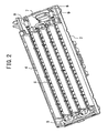
- Figure 2 is a perspective view of an inside of the discharge device in Embodiment 1 of the present invention. In Figure 2 , the upper frame 1 and the prefilter 3 are removed.
- the counter electrode 4 is fabricated by cutting and bending a plate-like metal member.
- the counter electrode 4 is preferably made of tungsten, copper, nickel, stainless, zinc, iron, molybdenum, or the like.
- the counter electrode 4 may be made of alloys mainly consisting of the above described metal, or the above described metal plated with noble metal such as silver, gold, or platinum.
- the counter electrode 4 is tilted by a predetermined angle with respect to the opening surface of the upper frame 1 and the opening surface of the lower frame 2.
- the counter electrode 4 has an angle of 45° to 60° with respect to the opening surface of the upper frame 1 and the opening surface of the lower frame 2.
- the metal counter electrode 4 is more precisely formed than a counter electrode 4 by resin molding. Changes in tilt with time of the metal counter electrode 4 are more significantly prevented than changes in tilt with time of the counter electrode 4 by resin molding.
- Figure 3 is a plan view of the end of the discharge electrode of the discharge device in Embodiment 1 of the present invention.
- the discharge electrode 8 includes a discharge member 8a, a terminal 8b, and a tube 8c.
- the discharge member 8a is formed of a long plate-like or linear metal member.
- the discharge member 8a is preferably made of tungsten, copper, nickel, stainless, zinc, iron, molybdenum, or the like.
- the discharge member 8a may be made of alloys mainly consisting of the above described metal, or the above described metal plated with noble metal such as silver, gold, or platinum, or having a carbon (graphite) layer or an oxide film.
- the discharge member 8a as a plate-like member has a rectangular section surrounded by short and long sides.
- the short side has a length of 0.01 to 0.1 mm.
- the long side has a length of 0.1 to 1.0 mm.
- the terminal 8b is looped so as to be easily mounted to the spring 9.
- the terminal 8b is mounted to each end of the discharge member 8a by crimping or welding.
- the terminal 8b is made of stainless, nickel, tin, aluminum, brass, copper, or the like.
- the terminal 8b may be made of alloys mainly consisting of the above described metal, or the above described metal plated with noble metal such as silver, gold, or platinum, or plated with stainless, nickel, tin, aluminum, brass, copper, or the like.
- the tube 8c has an electrically insulating property.
- the tube 8c covers a mounting portion between the discharge member 8a and the terminal 8b.
- the tube 8c covers the discharge member 8a by a predetermined length from the mounting portion of the terminal 8b toward a center of the discharge member 8a in the longitudinal direction.
- the tube 8c is made of resin that does not generate ions by heat and has low hygroscopicity.
- the tube 8c is a heat shrinkable tube having flexibility, a tube having an inner surface to which an adhesive is applied, a heat shrinkable tube having an inner surface to which an adhesive is applied, or the like.
- the tube 8c desirably has such flexibility as to be bent to about 90° by hand.
- the tube 8c is a heat shrinkable tube
- the tube 8c is heated through the discharge member 8a and the terminal 8b.
- the heating shrinks the tube 8c.
- the tube 8c is secured to the discharge member 8a and the terminal 8b without any space therebetween.
- the tube 8c is a tube having an inner surface to which an adhesive is applied, the tube 8c is reliably secured to the discharge member 8a and the terminal 8b without any space therebetween.
- Silicone or the like may be poured into the space between the tube 8c, the discharge member 8a, and the terminal 8b. In this case, the silicone fills the space.
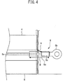
- Figure 4 is a schematic view showing a positional relationship between the end of the discharge electrode and the counter electrode in the discharge device of Embodiment I of the present invention.
- reference character A denotes a shortest distance between the terminal 8b and the end of the counter electrode 4.
- Reference character B denotes a length of the tube 8c.
- a left upper portion indicated by a broken line is a space (air trunk) through which air taken into the discharge device passes.
- an end of the terminal 8b on a side of the discharge member 8a is placed outside the counter electrode 4 when seen in a facing direction of the discharge member 8a and the counter electrode 4.
- the length B is longer than the shortest distance A.
- the tube 8c covers the discharge member 8a up to the space indicated by the broken line, through which air taken into the discharge device passes.
- the end of the tube 8c on the side of the discharge member 8a is placed closer to the space through which air passes than the end of the counter electrode 4.
- the mounting portion between the end of the discharge member 8a and the terminal 8b is covered with the tube 8c.
- the tube 8c covers the discharge member 8a by a predetermined length from the mounting portion between the end of the discharge member 8a and the terminal 8b toward the center of the discharge member 8a in the longitudinal direction. This increases strength of the discharge member 8a at the end of the terminal 8b. This can prevent cutting of the discharge member 8a.
- the tube 8c can be fitted in a slit in the second electrode support unit 6. This improves assemblability of the discharge electrode 8. Thus, yields in assembling are improved.
- a discharge portion can be located to the maximum in the space through which air passes. This can reduce an area of a portion supporting the discharge electrode 8. Thus, a thickness of the discharge device can be reduced to form a stable uniform electric field.
- the end of the tube 8c is secured to the mounting portion between the end of the discharge member 8a and the terminal 8b without any space therebetween by heat shrinkage or bonding.
- This can prevent air and water from entering a fitting portion between the discharge member 8a and the terminal 8b, prevent development of corrosion of the discharge member 8a and the terminal 8b, and reliably prevent a problem such as disconnection.
- the joining can be held by bonding, thereby allowing energization and maintaining performance over a long period.
- the tube 8c is made of resin that does not generate ions by heating and has low hygroscopicity. Thus, even in an environment with high temperature or humidity, the tube 8c does not generate gas.
- the tube 8c has a low amount of moisture absorption. This prevents water from coming into contact with the discharge member 8a. Thus, corrosion of the discharge member 8a can be prevented.
- the tube 8c has flexibility. In this case, the tube 8c is not cut even if the discharge member 8a is twisted with respect to the terminal 8b. This reliably avoids cutting of the discharge member 8a at the end of the terminal 8b in assembling. If the tube 8c does not have flexibility, the discharge member 8a may be bent at the end of the tube 8c and cut in assembling, but such a possibility can be eliminated to facilitate assembling.
- the tube is longer in the longitudinal direction of the discharge member 8a than the shortest distance between the terminal 8b and the end of the counter electrode 4.
- the tube 8c extends into the air trunk in which the discharge member 8a and the counter electrode 4 face each other.
- the end of the tube 8c on the side of the discharge member 8a is placed closer to the air trunk than the end of the counter electrode 4.
- the discharge member 8a and the terminal 8b are desirably made of metals having close potentials. A large potential difference between metals easily causes corrosion due to the potential difference.
- the terminal 8b is preferably made of tin, nickel, or tin-plated or nickel-plated metal. In this case, corrosion hardly occurs between dissimilar metals of the discharge member 8a and the terminal 8b. This increases durability of the discharge member 8a and the terminal 8b.
- the discharge member 8a may be tungsten having a carbon (graphite) layer. In this case, the discharge member 8a and the terminal 8b are not both metal, thereby preventing corrosion due to a potential difference. A desirable potential difference is about 0.1 V or less.
- SnO as an oxide is not dissolved in water and does not accelerate corrosion.
- Figure 5 is a vertical sectional view of an indoor unit of an air conditioner including a discharge device according to Embodiment 2 of the present invention.
- an inlet port 11 is formed in an upper surface of a body 10 of the inner unit of the air conditioner.
- An outlet port 12 is formed in a lower portion of a front surface of the body 10.
- a blast fan not shown
- a heat exchanger 13 is provided in the body 10.
- the blast fan is a propeller fan, a line flow fan, or the like.
- the blast fan is a line flow fan
- the heat exchanger 13 is placed above the outlet port 12 on a windward side of the blast fan.
- the blast fan is a propeller fan
- the heat exchanger 13 is placed above the outlet port 12 on a leeward side of the blast fan.
- the discharge device 14 When the blast fan is a line flow fan, the discharge device 14 is placed on the windward side of the blast fan and a windward side of the heat exchanger 13. When the blast fan is a propeller fan, the discharge device 14 is placed on the leeward side of the blast fan and a windward side of the heat exchanger 13. The discharge device 14 is placed diagonally along a tilt of an upper surface of the heat exchanger 13. Thus, an opening surface of an upper frame 1 and an opening surface of a lower frame 2 in the discharge device 14 are tilted. Thus, a counter electrode 4 is placed almost vertically.
- the air fed from the blast fan diagonally flows into the discharge device 14, and moves in the discharge device 14 along the tilt of the counter electrode 4.
- the air discharged from the discharge device 14 flows into the heat exchanger 13.
- the air having passed through the heat exchanger 13 is discharged from the outlet port 12 to the outside of the body 10.
- the discharge device 14 placed in the body 10 can remove and inactivate bacteria, mold, viruses, or the like suspended in a room.
- the air fed from the blast fan diagonally flows into the discharge device 14. This prevents large pressure loss in the discharge device 14.
- the air conditioner includes the discharge device 14 therein, cooling and heating functions of the air conditioner are not significantly reduced.
- the discharge device can be provided in products such as a room air conditioner, a package air conditioner, a cleaner, a hand drier, an air cleaner, a humidifier, a dehumidifier, or a refrigerator.
Landscapes
- Engineering & Computer Science (AREA)
- Chemical & Material Sciences (AREA)
- Combustion & Propulsion (AREA)
- Mechanical Engineering (AREA)
- General Engineering & Computer Science (AREA)
- Physics & Mathematics (AREA)
- Plasma & Fusion (AREA)
- Health & Medical Sciences (AREA)
- Spectroscopy & Molecular Physics (AREA)
- Epidemiology (AREA)
- Life Sciences & Earth Sciences (AREA)
- Animal Behavior & Ethology (AREA)
- General Health & Medical Sciences (AREA)
- Public Health (AREA)
- Veterinary Medicine (AREA)
- Disinfection, Sterilisation Or Deodorisation Of Air (AREA)
Applications Claiming Priority (1)
| Application Number | Priority Date | Filing Date | Title |
|---|---|---|---|
| PCT/JP2012/066126 WO2014002158A1 (ja) | 2012-06-25 | 2012-06-25 | 放電装置 |
Publications (3)
| Publication Number | Publication Date |
|---|---|
| EP2701252A1 true EP2701252A1 (de) | 2014-02-26 |
| EP2701252A4 EP2701252A4 (de) | 2014-12-17 |
| EP2701252B1 EP2701252B1 (de) | 2020-01-01 |
Family
ID=49782394
Family Applications (1)
| Application Number | Title | Priority Date | Filing Date |
|---|---|---|---|
| EP12864678.3A Active EP2701252B1 (de) | 2012-06-25 | 2012-06-25 | Klimaanlage mit einer vorrichtung für elektrische entladung |
Country Status (4)
| Country | Link |
|---|---|
| EP (1) | EP2701252B1 (de) |
| JP (1) | JP5784717B2 (de) |
| CN (1) | CN203536732U (de) |
| WO (1) | WO2014002158A1 (de) |
Cited By (3)
| Publication number | Priority date | Publication date | Assignee | Title |
|---|---|---|---|---|
| EP2700452A3 (de) * | 2012-08-22 | 2017-12-27 | Mitsubishi Electric Corporation | Entladungsvorrichtung und Klimaanlage |
| CN110594872A (zh) * | 2019-09-30 | 2019-12-20 | 宁波奥克斯电气股份有限公司 | 一种空气净化方法、空气净化装置及空调器 |
| EP4295956A4 (de) * | 2021-02-18 | 2025-03-05 | Cedrión Consultoría Técnica e Ingeniería SL | Elektrohydrodynamische belüftungsvorrichtung |
Families Citing this family (3)
| Publication number | Priority date | Publication date | Assignee | Title |
|---|---|---|---|---|
| JP6863712B2 (ja) * | 2016-10-26 | 2021-04-21 | 住友金属鉱山エンジニアリング株式会社 | 放電線、及びその放電線を用いた湿式電気集塵装置 |
| CN109780627A (zh) * | 2019-01-31 | 2019-05-21 | 广东美的制冷设备有限公司 | 空调室内机和具有其的空调器 |
| CN114054207B (zh) * | 2020-07-30 | 2023-06-20 | Lg电子株式会社 | 电集尘用起电装置 |
Family Cites Families (8)
| Publication number | Priority date | Publication date | Assignee | Title |
|---|---|---|---|---|
| JPS6283551U (de) * | 1985-11-15 | 1987-05-28 | ||
| JPH03146148A (ja) * | 1989-11-02 | 1991-06-21 | Hitachi Ltd | 電気集麈装置 |
| JPH0638927B2 (ja) * | 1990-11-06 | 1994-05-25 | リンナイ株式会社 | 静電式空気清浄装置の電極 |
| JP2856585B2 (ja) * | 1991-12-13 | 1999-02-10 | 株式会社東芝 | 空気清浄器 |
| JPH0638927A (ja) | 1992-07-21 | 1994-02-15 | Olympus Optical Co Ltd | 内視鏡洗浄消毒装置 |
| JPH0838939A (ja) | 1994-07-29 | 1996-02-13 | Daikin Ind Ltd | イオン化線 |
| JP2005134648A (ja) * | 2003-10-30 | 2005-05-26 | Kyocera Mita Corp | スコロトロン帯電器 |
| JP2009230997A (ja) * | 2008-03-21 | 2009-10-08 | Autonetworks Technologies Ltd | 端子金具付き電線の製造方法及び端子金具付き電線 |
-
2012
- 2012-06-25 WO PCT/JP2012/066126 patent/WO2014002158A1/ja not_active Ceased
- 2012-06-25 EP EP12864678.3A patent/EP2701252B1/de active Active
- 2012-06-25 JP JP2013512681A patent/JP5784717B2/ja not_active Expired - Fee Related
- 2012-06-25 CN CN201290000242.5U patent/CN203536732U/zh not_active Expired - Lifetime
Cited By (3)
| Publication number | Priority date | Publication date | Assignee | Title |
|---|---|---|---|---|
| EP2700452A3 (de) * | 2012-08-22 | 2017-12-27 | Mitsubishi Electric Corporation | Entladungsvorrichtung und Klimaanlage |
| CN110594872A (zh) * | 2019-09-30 | 2019-12-20 | 宁波奥克斯电气股份有限公司 | 一种空气净化方法、空气净化装置及空调器 |
| EP4295956A4 (de) * | 2021-02-18 | 2025-03-05 | Cedrión Consultoría Técnica e Ingeniería SL | Elektrohydrodynamische belüftungsvorrichtung |
Also Published As
| Publication number | Publication date |
|---|---|
| EP2701252A4 (de) | 2014-12-17 |
| CN203536732U (zh) | 2014-04-09 |
| EP2701252B1 (de) | 2020-01-01 |
| JPWO2014002158A1 (ja) | 2016-05-26 |
| JP5784717B2 (ja) | 2015-09-24 |
| WO2014002158A1 (ja) | 2014-01-03 |
Similar Documents
| Publication | Publication Date | Title |
|---|---|---|
| EP2701252B1 (de) | Klimaanlage mit einer vorrichtung für elektrische entladung | |
| CN103623924B (zh) | 放电装置及空调机 | |
| CN203470159U (zh) | 放电装置及空调机 | |
| JP2014041754A5 (de) | ||
| JP2014039659A5 (de) | ||
| JP6612084B2 (ja) | イオン発生装置および電気機器 | |
| EP2768096B1 (de) | Vorrichtung zur erzeugung von elektrischen feldern und elektrischer entladung | |
| JP5935840B2 (ja) | 放電電極、放電装置 | |
| EP2865952B1 (de) | Klimaanlage | |
| WO2006085439A1 (ja) | 空気浄化装置 | |
| JP6123937B2 (ja) | 放電電極、放電装置 | |
| EP2682683B1 (de) | Klimaanlage | |
| JP2015131152A (ja) | 放電装置及び放電装置を備える製品 | |
| JP5968489B2 (ja) | 放電装置 | |
| JP5996034B2 (ja) | 放電装置及び放電装置を備える製品 | |
| JP5996035B2 (ja) | 放電装置及び放電装置を備える製品 | |
| CN103380552B (zh) | 电场及放电产生装置 | |
| JP2015131153A (ja) | 放電装置及び放電装置を備える製品 | |
| JP2006224102A (ja) | 空気浄化装置 |
Legal Events
| Date | Code | Title | Description |
|---|---|---|---|
| PUAI | Public reference made under article 153(3) epc to a published international application that has entered the european phase |
Free format text: ORIGINAL CODE: 0009012 |
|
| 17P | Request for examination filed |
Effective date: 20130715 |
|
| AK | Designated contracting states |
Kind code of ref document: A1 Designated state(s): AL AT BE BG CH CY CZ DE DK EE ES FI FR GB GR HR HU IE IS IT LI LT LU LV MC MK MT NL NO PL PT RO RS SE SI SK SM TR |
|
| A4 | Supplementary search report drawn up and despatched |
Effective date: 20141118 |
|
| RIC1 | Information provided on ipc code assigned before grant |
Ipc: H01T 19/00 20060101AFI20141112BHEP Ipc: B03C 3/41 20060101ALI20141112BHEP Ipc: F24F 1/00 20110101ALI20141112BHEP Ipc: B03C 3/47 20060101ALI20141112BHEP Ipc: H05H 1/48 20060101ALI20141112BHEP Ipc: B03C 3/38 20060101ALI20141112BHEP Ipc: F24F 3/16 20060101ALI20141112BHEP Ipc: B03C 3/12 20060101ALI20141112BHEP Ipc: F24F 1/02 20110101ALI20141112BHEP Ipc: H01T 13/16 20060101ALI20141112BHEP Ipc: A61L 9/22 20060101ALI20141112BHEP Ipc: B03C 3/09 20060101ALI20141112BHEP |
|
| DAX | Request for extension of the european patent (deleted) | ||
| STAA | Information on the status of an ep patent application or granted ep patent |
Free format text: STATUS: EXAMINATION IS IN PROGRESS |
|
| 17Q | First examination report despatched |
Effective date: 20190208 |
|
| REG | Reference to a national code |
Ref country code: DE Ref legal event code: R079 Ref document number: 602012066999 Country of ref document: DE Free format text: PREVIOUS MAIN CLASS: H01T0019000000 Ipc: F24F0001007600 |
|
| GRAP | Despatch of communication of intention to grant a patent |
Free format text: ORIGINAL CODE: EPIDOSNIGR1 |
|
| STAA | Information on the status of an ep patent application or granted ep patent |
Free format text: STATUS: GRANT OF PATENT IS INTENDED |
|
| RIC1 | Information provided on ipc code assigned before grant |
Ipc: F24F 1/00 20190101ALI20190702BHEP Ipc: H05H 1/48 20060101ALI20190702BHEP Ipc: F24F 1/02 20190101ALI20190702BHEP Ipc: H01T 19/00 20060101ALI20190702BHEP Ipc: B03C 3/47 20060101ALI20190702BHEP Ipc: B03C 3/09 20060101ALI20190702BHEP Ipc: B03C 3/12 20060101ALI20190702BHEP Ipc: F24F 1/0076 20190101AFI20190702BHEP Ipc: B03C 3/41 20060101ALI20190702BHEP Ipc: A61L 9/22 20060101ALI20190702BHEP Ipc: B03C 3/38 20060101ALI20190702BHEP Ipc: H01T 23/00 20060101ALI20190702BHEP |
|
| INTG | Intention to grant announced |
Effective date: 20190718 |
|
| GRAS | Grant fee paid |
Free format text: ORIGINAL CODE: EPIDOSNIGR3 |
|
| GRAA | (expected) grant |
Free format text: ORIGINAL CODE: 0009210 |
|
| STAA | Information on the status of an ep patent application or granted ep patent |
Free format text: STATUS: THE PATENT HAS BEEN GRANTED |
|
| AK | Designated contracting states |
Kind code of ref document: B1 Designated state(s): AL AT BE BG CH CY CZ DE DK EE ES FI FR GB GR HR HU IE IS IT LI LT LU LV MC MK MT NL NO PL PT RO RS SE SI SK SM TR |
|
| REG | Reference to a national code |
Ref country code: GB Ref legal event code: FG4D |
|
| REG | Reference to a national code |
Ref country code: CH Ref legal event code: EP Ref country code: AT Ref legal event code: REF Ref document number: 1220241 Country of ref document: AT Kind code of ref document: T Effective date: 20200115 |
|
| REG | Reference to a national code |
Ref country code: IE Ref legal event code: FG4D |
|
| REG | Reference to a national code |
Ref country code: DE Ref legal event code: R096 Ref document number: 602012066999 Country of ref document: DE |
|
| REG | Reference to a national code |
Ref country code: SE Ref legal event code: TRGR |
|
| REG | Reference to a national code |
Ref country code: NL Ref legal event code: MP Effective date: 20200101 |
|
| REG | Reference to a national code |
Ref country code: LT Ref legal event code: MG4D |
|
| PG25 | Lapsed in a contracting state [announced via postgrant information from national office to epo] |
Ref country code: FI Free format text: LAPSE BECAUSE OF FAILURE TO SUBMIT A TRANSLATION OF THE DESCRIPTION OR TO PAY THE FEE WITHIN THE PRESCRIBED TIME-LIMIT Effective date: 20200101 Ref country code: NO Free format text: LAPSE BECAUSE OF FAILURE TO SUBMIT A TRANSLATION OF THE DESCRIPTION OR TO PAY THE FEE WITHIN THE PRESCRIBED TIME-LIMIT Effective date: 20200401 Ref country code: LT Free format text: LAPSE BECAUSE OF FAILURE TO SUBMIT A TRANSLATION OF THE DESCRIPTION OR TO PAY THE FEE WITHIN THE PRESCRIBED TIME-LIMIT Effective date: 20200101 Ref country code: CZ Free format text: LAPSE BECAUSE OF FAILURE TO SUBMIT A TRANSLATION OF THE DESCRIPTION OR TO PAY THE FEE WITHIN THE PRESCRIBED TIME-LIMIT Effective date: 20200101 Ref country code: NL Free format text: LAPSE BECAUSE OF FAILURE TO SUBMIT A TRANSLATION OF THE DESCRIPTION OR TO PAY THE FEE WITHIN THE PRESCRIBED TIME-LIMIT Effective date: 20200101 Ref country code: PT Free format text: LAPSE BECAUSE OF FAILURE TO SUBMIT A TRANSLATION OF THE DESCRIPTION OR TO PAY THE FEE WITHIN THE PRESCRIBED TIME-LIMIT Effective date: 20200527 Ref country code: RS Free format text: LAPSE BECAUSE OF FAILURE TO SUBMIT A TRANSLATION OF THE DESCRIPTION OR TO PAY THE FEE WITHIN THE PRESCRIBED TIME-LIMIT Effective date: 20200101 |
|
| PG25 | Lapsed in a contracting state [announced via postgrant information from national office to epo] |
Ref country code: GR Free format text: LAPSE BECAUSE OF FAILURE TO SUBMIT A TRANSLATION OF THE DESCRIPTION OR TO PAY THE FEE WITHIN THE PRESCRIBED TIME-LIMIT Effective date: 20200402 Ref country code: HR Free format text: LAPSE BECAUSE OF FAILURE TO SUBMIT A TRANSLATION OF THE DESCRIPTION OR TO PAY THE FEE WITHIN THE PRESCRIBED TIME-LIMIT Effective date: 20200101 Ref country code: LV Free format text: LAPSE BECAUSE OF FAILURE TO SUBMIT A TRANSLATION OF THE DESCRIPTION OR TO PAY THE FEE WITHIN THE PRESCRIBED TIME-LIMIT Effective date: 20200101 Ref country code: IS Free format text: LAPSE BECAUSE OF FAILURE TO SUBMIT A TRANSLATION OF THE DESCRIPTION OR TO PAY THE FEE WITHIN THE PRESCRIBED TIME-LIMIT Effective date: 20200501 Ref country code: BG Free format text: LAPSE BECAUSE OF FAILURE TO SUBMIT A TRANSLATION OF THE DESCRIPTION OR TO PAY THE FEE WITHIN THE PRESCRIBED TIME-LIMIT Effective date: 20200401 |
|
| REG | Reference to a national code |
Ref country code: DE Ref legal event code: R097 Ref document number: 602012066999 Country of ref document: DE |
|
| PG25 | Lapsed in a contracting state [announced via postgrant information from national office to epo] |
Ref country code: ES Free format text: LAPSE BECAUSE OF FAILURE TO SUBMIT A TRANSLATION OF THE DESCRIPTION OR TO PAY THE FEE WITHIN THE PRESCRIBED TIME-LIMIT Effective date: 20200101 Ref country code: RO Free format text: LAPSE BECAUSE OF FAILURE TO SUBMIT A TRANSLATION OF THE DESCRIPTION OR TO PAY THE FEE WITHIN THE PRESCRIBED TIME-LIMIT Effective date: 20200101 Ref country code: SM Free format text: LAPSE BECAUSE OF FAILURE TO SUBMIT A TRANSLATION OF THE DESCRIPTION OR TO PAY THE FEE WITHIN THE PRESCRIBED TIME-LIMIT Effective date: 20200101 Ref country code: EE Free format text: LAPSE BECAUSE OF FAILURE TO SUBMIT A TRANSLATION OF THE DESCRIPTION OR TO PAY THE FEE WITHIN THE PRESCRIBED TIME-LIMIT Effective date: 20200101 Ref country code: DK Free format text: LAPSE BECAUSE OF FAILURE TO SUBMIT A TRANSLATION OF THE DESCRIPTION OR TO PAY THE FEE WITHIN THE PRESCRIBED TIME-LIMIT Effective date: 20200101 Ref country code: SK Free format text: LAPSE BECAUSE OF FAILURE TO SUBMIT A TRANSLATION OF THE DESCRIPTION OR TO PAY THE FEE WITHIN THE PRESCRIBED TIME-LIMIT Effective date: 20200101 |
|
| PLBE | No opposition filed within time limit |
Free format text: ORIGINAL CODE: 0009261 |
|
| STAA | Information on the status of an ep patent application or granted ep patent |
Free format text: STATUS: NO OPPOSITION FILED WITHIN TIME LIMIT |
|
| REG | Reference to a national code |
Ref country code: AT Ref legal event code: MK05 Ref document number: 1220241 Country of ref document: AT Kind code of ref document: T Effective date: 20200101 |
|
| 26N | No opposition filed |
Effective date: 20201002 |
|
| PG25 | Lapsed in a contracting state [announced via postgrant information from national office to epo] |
Ref country code: AT Free format text: LAPSE BECAUSE OF FAILURE TO SUBMIT A TRANSLATION OF THE DESCRIPTION OR TO PAY THE FEE WITHIN THE PRESCRIBED TIME-LIMIT Effective date: 20200101 Ref country code: MC Free format text: LAPSE BECAUSE OF FAILURE TO SUBMIT A TRANSLATION OF THE DESCRIPTION OR TO PAY THE FEE WITHIN THE PRESCRIBED TIME-LIMIT Effective date: 20200101 |
|
| REG | Reference to a national code |
Ref country code: CH Ref legal event code: PL |
|
| PG25 | Lapsed in a contracting state [announced via postgrant information from national office to epo] |
Ref country code: PL Free format text: LAPSE BECAUSE OF FAILURE TO SUBMIT A TRANSLATION OF THE DESCRIPTION OR TO PAY THE FEE WITHIN THE PRESCRIBED TIME-LIMIT Effective date: 20200101 Ref country code: SI Free format text: LAPSE BECAUSE OF FAILURE TO SUBMIT A TRANSLATION OF THE DESCRIPTION OR TO PAY THE FEE WITHIN THE PRESCRIBED TIME-LIMIT Effective date: 20200101 |
|
| GBPC | Gb: european patent ceased through non-payment of renewal fee |
Effective date: 20200625 |
|
| PG25 | Lapsed in a contracting state [announced via postgrant information from national office to epo] |
Ref country code: LU Free format text: LAPSE BECAUSE OF NON-PAYMENT OF DUE FEES Effective date: 20200625 |
|
| REG | Reference to a national code |
Ref country code: BE Ref legal event code: MM Effective date: 20200630 |
|
| PG25 | Lapsed in a contracting state [announced via postgrant information from national office to epo] |
Ref country code: GB Free format text: LAPSE BECAUSE OF NON-PAYMENT OF DUE FEES Effective date: 20200625 Ref country code: FR Free format text: LAPSE BECAUSE OF NON-PAYMENT OF DUE FEES Effective date: 20200630 Ref country code: CH Free format text: LAPSE BECAUSE OF NON-PAYMENT OF DUE FEES Effective date: 20200630 Ref country code: LI Free format text: LAPSE BECAUSE OF NON-PAYMENT OF DUE FEES Effective date: 20200630 Ref country code: IE Free format text: LAPSE BECAUSE OF NON-PAYMENT OF DUE FEES Effective date: 20200625 |
|
| PG25 | Lapsed in a contracting state [announced via postgrant information from national office to epo] |
Ref country code: BE Free format text: LAPSE BECAUSE OF NON-PAYMENT OF DUE FEES Effective date: 20200630 |
|
| PG25 | Lapsed in a contracting state [announced via postgrant information from national office to epo] |
Ref country code: TR Free format text: LAPSE BECAUSE OF FAILURE TO SUBMIT A TRANSLATION OF THE DESCRIPTION OR TO PAY THE FEE WITHIN THE PRESCRIBED TIME-LIMIT Effective date: 20200101 Ref country code: MT Free format text: LAPSE BECAUSE OF FAILURE TO SUBMIT A TRANSLATION OF THE DESCRIPTION OR TO PAY THE FEE WITHIN THE PRESCRIBED TIME-LIMIT Effective date: 20200101 Ref country code: CY Free format text: LAPSE BECAUSE OF FAILURE TO SUBMIT A TRANSLATION OF THE DESCRIPTION OR TO PAY THE FEE WITHIN THE PRESCRIBED TIME-LIMIT Effective date: 20200101 |
|
| PG25 | Lapsed in a contracting state [announced via postgrant information from national office to epo] |
Ref country code: MK Free format text: LAPSE BECAUSE OF FAILURE TO SUBMIT A TRANSLATION OF THE DESCRIPTION OR TO PAY THE FEE WITHIN THE PRESCRIBED TIME-LIMIT Effective date: 20200101 Ref country code: AL Free format text: LAPSE BECAUSE OF FAILURE TO SUBMIT A TRANSLATION OF THE DESCRIPTION OR TO PAY THE FEE WITHIN THE PRESCRIBED TIME-LIMIT Effective date: 20200101 |
|
| P01 | Opt-out of the competence of the unified patent court (upc) registered |
Effective date: 20230512 |
|
| REG | Reference to a national code |
Ref country code: DE Ref legal event code: R084 Ref document number: 602012066999 Country of ref document: DE |
|
| PGFP | Annual fee paid to national office [announced via postgrant information from national office to epo] |
Ref country code: DE Payment date: 20240502 Year of fee payment: 13 |
|
| PGFP | Annual fee paid to national office [announced via postgrant information from national office to epo] |
Ref country code: IT Payment date: 20240513 Year of fee payment: 13 |
|
| PGFP | Annual fee paid to national office [announced via postgrant information from national office to epo] |
Ref country code: SE Payment date: 20240510 Year of fee payment: 13 |
|
| REG | Reference to a national code |
Ref country code: DE Ref legal event code: R085 Ref document number: 602012066999 Country of ref document: DE |
|
| REG | Reference to a national code |
Ref country code: DE Ref legal event code: R119 Ref document number: 602012066999 Country of ref document: DE |
|
| REG | Reference to a national code |
Ref country code: SE Ref legal event code: EUG |
|
| PG25 | Lapsed in a contracting state [announced via postgrant information from national office to epo] |
Ref country code: DE Free format text: LAPSE BECAUSE OF NON-PAYMENT OF DUE FEES Effective date: 20260101 |
|
| PG25 | Lapsed in a contracting state [announced via postgrant information from national office to epo] |
Ref country code: IT Free format text: LAPSE BECAUSE OF NON-PAYMENT OF DUE FEES Effective date: 20250625 |