EP2701862B1 - Procédé et dispositif pour fabriquer de pièces embouties dotées d'une bride en les ébarbant simultanément - Google Patents
Procédé et dispositif pour fabriquer de pièces embouties dotées d'une bride en les ébarbant simultanément Download PDFInfo
- Publication number
- EP2701862B1 EP2701862B1 EP12717670.9A EP12717670A EP2701862B1 EP 2701862 B1 EP2701862 B1 EP 2701862B1 EP 12717670 A EP12717670 A EP 12717670A EP 2701862 B1 EP2701862 B1 EP 2701862B1
- Authority
- EP
- European Patent Office
- Prior art keywords
- region
- blank
- cutting edge
- drawing die
- flange
- Prior art date
- Legal status (The legal status is an assumption and is not a legal conclusion. Google has not performed a legal analysis and makes no representation as to the accuracy of the status listed.)
- Active
Links
- 238000000034 method Methods 0.000 title claims description 50
- 238000009966 trimming Methods 0.000 title description 20
- 238000005520 cutting process Methods 0.000 claims description 84
- 239000000463 material Substances 0.000 claims description 12
- 238000004519 manufacturing process Methods 0.000 claims description 6
- 239000002184 metal Substances 0.000 claims description 2
- 230000007704 transition Effects 0.000 claims description 2
- 239000011265 semifinished product Substances 0.000 description 4
- 238000013461 design Methods 0.000 description 3
- 238000010276 construction Methods 0.000 description 2
- 238000007373 indentation Methods 0.000 description 2
- 230000003993 interaction Effects 0.000 description 2
- 238000007790 scraping Methods 0.000 description 2
- 229910000831 Steel Inorganic materials 0.000 description 1
- 238000007796 conventional method Methods 0.000 description 1
- 238000003780 insertion Methods 0.000 description 1
- 230000037431 insertion Effects 0.000 description 1
- 238000012423 maintenance Methods 0.000 description 1
- BASFCYQUMIYNBI-UHFFFAOYSA-N platinum Chemical compound [Pt] BASFCYQUMIYNBI-UHFFFAOYSA-N 0.000 description 1
- 238000004080 punching Methods 0.000 description 1
- 238000000926 separation method Methods 0.000 description 1
- 239000010959 steel Substances 0.000 description 1
Images
Classifications
-
- B—PERFORMING OPERATIONS; TRANSPORTING
- B21—MECHANICAL METAL-WORKING WITHOUT ESSENTIALLY REMOVING MATERIAL; PUNCHING METAL
- B21D—WORKING OR PROCESSING OF SHEET METAL OR METAL TUBES, RODS OR PROFILES WITHOUT ESSENTIALLY REMOVING MATERIAL; PUNCHING METAL
- B21D22/00—Shaping without cutting, by stamping, spinning, or deep-drawing
- B21D22/02—Stamping using rigid devices or tools
-
- B—PERFORMING OPERATIONS; TRANSPORTING
- B21—MECHANICAL METAL-WORKING WITHOUT ESSENTIALLY REMOVING MATERIAL; PUNCHING METAL
- B21D—WORKING OR PROCESSING OF SHEET METAL OR METAL TUBES, RODS OR PROFILES WITHOUT ESSENTIALLY REMOVING MATERIAL; PUNCHING METAL
- B21D22/00—Shaping without cutting, by stamping, spinning, or deep-drawing
- B21D22/20—Deep-drawing
- B21D22/22—Deep-drawing with devices for holding the edge of the blanks
-
- B—PERFORMING OPERATIONS; TRANSPORTING
- B21—MECHANICAL METAL-WORKING WITHOUT ESSENTIALLY REMOVING MATERIAL; PUNCHING METAL
- B21D—WORKING OR PROCESSING OF SHEET METAL OR METAL TUBES, RODS OR PROFILES WITHOUT ESSENTIALLY REMOVING MATERIAL; PUNCHING METAL
- B21D22/00—Shaping without cutting, by stamping, spinning, or deep-drawing
- B21D22/20—Deep-drawing
- B21D22/30—Deep-drawing to finish articles formed by deep-drawing
-
- B—PERFORMING OPERATIONS; TRANSPORTING
- B21—MECHANICAL METAL-WORKING WITHOUT ESSENTIALLY REMOVING MATERIAL; PUNCHING METAL
- B21D—WORKING OR PROCESSING OF SHEET METAL OR METAL TUBES, RODS OR PROFILES WITHOUT ESSENTIALLY REMOVING MATERIAL; PUNCHING METAL
- B21D24/00—Special deep-drawing arrangements in, or in connection with, presses
- B21D24/16—Additional equipment in association with the tools, e.g. for shearing, for trimming
Definitions
- the invention relates to a method and an apparatus for producing flanged drawn parts from a flat and / or preformed metal board using a drawing die with at least one cutting edge, a blank holder and a drawing die, wherein the drawing die a frame portion, a flange portion and a support area for has the board, the board placed on the support area of the drawing die and formed by retracting the draw punch in the drawing die in the drawn part and simultaneously cut at the flange.
- the invention relates to a device for producing flanged drawn parts with a drawing punch, which has at least one cutting edge, at least one hold-down and a drawing die with a flange portion in which the flange is formed, a frame portion and bottom portion, in which Zargen- and bottom portion formed and a support area for the board before the drawing process.
- Deep-drawing presses do not have a high-precision tool guide, so that trimming operations in such presses are not possible or can only be carried out very difficult and expensive.
- WO 2008/025387 A1 discloses a method and a tool for hot working a circuit board, wherein cutting elements are provided in the dies of the tool. With the cutting elements, a trimming of the workpiece can be carried out simultaneously with the drawing process.
- the DE 10 2006 026 805 A1 discloses an apparatus and method for hot working a semi-finished product having a die, a punch and a blank holder.
- a cutting device is provided on the punch and die, which cuts the semi-finished during forming.
- the present invention has therefore set itself the task of providing a method and an apparatus for producing flanged drawn parts with process-integrated trimming, which or a simpler construction of the tool, a self-centering system and at the same time a process-reliable, dimensionally accurate production of allows flange-drawn parts.
- the object of a method is achieved in that the Bearing area increased relative to the flange and fixed, wherein the height difference corresponds to at least the wall thickness of the formed sheet, during the retraction of the drawing die in the drawing die the cutting punch provided on the cutting edge with a provided at the transition between support area and flange area rounding, so that over the flange area projecting areas of the board are separated during the further drawing process.
- the support area is raised in relation to the flange area and formed in a fixed manner, so that the tool as a whole can be of considerably simplified construction. Because the height difference between the support area and the flange area of the die corresponds at least to the thickness of the board, a perfect cutting process with the cutting edge of the drawing punch or the drawing die can be ensured. In addition, the fact that the at least one provided on the drawing punch Cutting edge engages with the provided between the support portion and flange portion rounding before completion of the drawing process, allows, in contrast to the conventional method, the flange portion is cut before the completion of the drawing operation.
- the method thus allows a particularly simple design of the tool, which manages without height-shifting areas and offers high flexibility of the arrangement of the flange.
- the infeed of the board during the drawing process can be controlled or adjusted via the height difference between the support area and the flange area as well as over the flange area width.
- the material flow during the drawing process and trimming is easily controllable in that the hold-down presses the region of the board to be severed during the drawing process and trimming the region of the board to be cut off onto the support region of the drawing die.
- the tensile load of the board during trimming thereby adjusted and thus influence the Cutting quality are taken.
- the semifinished product can in particular be clamped and stretched wrinkle-free.
- the rounding along the cutting line has a varying engagement height with the cutting edge of the drawing punch, wherein the board is continuously cut during the retraction of the draw punch into the drawing die, starting from the areas of the curves which are first engaged with the cutting edge of the drawing punch becomes.
- the cutting forces and the cutting stroke can be reduced significantly.
- the engagement height varying along the cutting line with the cutting edge of the drawing punch of the rounding ensures that the cutting edge of the drawing punch comes into engagement with the round at different timings of the drawing punch, so that the trimming of the board respectively first into the first engaged Begins areas of rounding and then propagates continuously towards the other areas.
- the cutting line formed by the rounding with the cutting edge can then have, for example, a wavy course or an inclined course.
- the rounding has a radius of at least 0.5 mm.
- a cutting edge with a maximum radius of 0.5 mm.
- the tool Due to the interaction of the cutting edge (sharp edge) with the rounding, the tool is self-centering and thus positively influences the cutting quality.
- the dimensional accuracy of the manufactured, flanged drawn parts can be further improved in a further embodiment of the method according to the invention that the board is pulled into a preform before pulling in the drawing die in a Vorziehgesenk and the preformed board provides a surplus of material, so that upon reaching the end position of the Drawing die the finished shaped and trimmed board is calibrated.
- the excess material can preferably be provided in the bottom region and / or in the drawing radius.
- the process can be further improved by hot-working the board in the drawing die.
- this is also optional for the preforming process.
- the blanks are heated to austenitizing temperature, thermoformed and rapidly cooled so that the drawn part is press hardened.
- lower forming forces result, on the other hand, a structure which is advantageous for the forming and which permits large degrees of deformation.
- the hot forming is used in blanks made of higher-strength or ultrahigh-strength steels, for example of the 22MnB5 type.
- the method according to the invention it is also possible, according to a further embodiment of the method according to the invention, to leave material along the cutting line, preferably in the form of webs, in other words. to produce an interrupted cutting line, whereby the drawn part is at least partially still connected to the trim area and at the same time can be removed from the tool (scrap removal via webs). In a further separation process, the cut area can be separated from the good part.
- a slit semifinished product which has at least one slot, preferably at least two slits in the trimming area, which extends from an edge of the semi-finished product to the cutting line, whereby the trimming area is divided into several individual parts during the trimming (Scrap division) and thus the bad part can be removed more easily from the tool, for example by means of scrap chutes.
- the object is achieved by a device in that the support area is increased and fixed with respect to the flange area, wherein the height difference between the support area and the flange portion of the drawing die corresponds at least to the wall thickness of the board to be formed, between Supporting portion and the flange portion is provided a rounding, which is in engagement with a cutting punch provided on the cutting edge and allows trimming of the board during the drawing process.
- the device according to the invention does not require a height-adjustable drawing die, so that the costs for the production of the train can be significantly reduced.
- the difference in height between the support area of the board and the flange area allows the flange of the drawn part to be formed very precisely into the flange area after it has been trimmed.
- the device allows a greater flexibility with respect to the orientation of the flange portion relative to the frame portion is achieved. The cost-effective tool with its simple design reduces wear and thus the cost of producing precise, flanged drawing parts.
- the indentation of the flange area of the drawn part can be controlled or adjusted via the height difference or over the flange width.
- a larger height difference between support area and flange area allows more material to be provided here and the flange area to have less feed.
- a minimum indentation must be ensured so that the drawn drawn part can still be removed from the tool.
- the rounding has an inlet radius of at least 0.5 mm.
- the precision of trimming the flange of the drawn part is improved in that the cutting edge of the drawing punch has a maximum radius of 0.5 mm.
- the rounding along the cutting line on a varying engagement height with the cutting edge so that the cutting edge at the beginning of the cutting process only point or area with the rounding engaged.
- the rounding which varies in its engagement height with the cutting edge, permits a continuous trimming along the cutting line by retracting the drawing punch into the drawing die.
- the cutting forces and the cutting impact during the drawing process are significantly reduced.
- the device according to the invention can be further improved in that the support area is connected to the drawing die in a highly precise manner, for example via a pinning, or is formed integrally with the drawing die. If the support area is formed integrally with the drawing die, the drawing die can be produced particularly inexpensively. On the other hand, there are significant advantages in the pinning of the support area with the drawing die in terms of maintenance. In this case, it is possible to replace the support area and possibly rework the rounding or cutting edge of the drawing die in a simple manner.
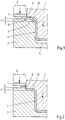
- FIG. 1 a first embodiment of a device according to the invention for the production of flanged drawing parts with a drawing punch 1, a drawing die 2 with a flange 3, in which the flange is formed, a frame portion 4 and a bottom portion 5, in which the Zargen- or bottom portions of the drawn part formed be and a support area 6 for supporting the board before the drawing process.
- the Device on a hold-7 and a rounding 8 between support area 6 and the flange portion 3.
- the rounding has an inlet radius of at least 0.5 mm, so that the material from the support area 6 can flow unhindered into the flange area.
- the support area 6 is raised relative to the flange area 3 and formed fixed.
- h indicates the height difference between the supporting area for the drawing board of the drawing die 6 and the flange area 3 of the drawing die. In the embodiment shown, h is slightly larger than the board thickness.
- the directional arrows each indicate the direction of movement of the blank holder 7 and the drawing punch 1.
- the drawing punch 1 also has a cutting edge 9, which preferably has a radius of 0.05 mm. As in Fig. 1 As shown, in the drawing process, the blank 10 is pulled into the drawing die until the cutting edge 9 engages the rounding 8. Preferably, the hold-down is shut down at the beginning of the drawing process, so that it presses the board 10 against the support area 6 of the board. By this measure, the flow of material can be additionally controlled during the drawing process.
- the drawing punch 1 moves the drawing punch 1, as in Fig. 2 shown, in the end position, the circuit board is cut due to the engagement of the cutting edge 9 of the drawing punch 1 with the rounding 8 of the support portion 6, so that over the flange portion 3 protruding parts of the board 10 are separated from this.
- the drawing die 2 is particularly simple design and still allows deep drawing with simultaneous trimming of the board.
- the support area 6 is in the present embodiment formed integrally with the drawing die, which corresponds to a particularly simple embodiment.
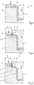
- Fig. 3 now shows in a schematic sectional view of a half of a device 11 for producing a preformed circuit board 12, which provides, for example in the bottom area a surplus of material.
- the device 11 for producing a preformed circuit board also consists of a die 13 and a drawing punch 14 and a hold-down 15.
- the preformed board 12 inserted in a device can not only be drawn to the final shape, but also circumcised and calibrated simultaneously.
- the preformed board 12 can not only be drawn to the final shape, but also circumcised and calibrated simultaneously.
- the drawing die 2 provided in the bottom region 5 of the drawing die excess material of the preformed board.
- a cutting edge 8 'and the drawing punch 1 a rounding 9' are provided.
- Fig. 5 shows schematically a device in the final position of the drawing die with calibrated, preformed board 12. The insertion of the board in the flange area is minimal and thus the drawn part so very accurate.
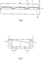
- Fig. 6 the rounding 8 between support area 6 and flange area 3 is shown schematically along its section line 8b.
- the section line 8b of the rounding 8 has a wave-shaped course, so that the cutting edge 9 of the drawing punch at the beginning of the cutting process only point or partially with the rounding 8 engages and the board can be continuously cut by retracting the drawing punch in the drawing die.
- 8a the target section contour of the rounding 8 is designated, which corresponds to the desired dimension of the board.
- the representation in Fig. 6 is not to scale. About a calibration, such as in 4 and 5 shown, the rounding can be easily corrected in one step.
- a sawtooth or a linear profile of the engagement height of the rounding can be used.
- Fig. 7 has on the left side of the rounding 8 a small inlet radius, for example, 1 mm.
- the inlet radius is significantly larger, for example, 5 mm. Accordingly, the cutting edge initially engages the left side first and continues its cut to the right side by retracting the draw punch into the die.
- the cutting gaps which are provided between the cutting edge 9, 8 'and rounding 8, 9', are preferably 0.05 mm to a maximum of 0.2 mm in order to ensure a particularly precise trimming of the board.
- the cutting edge of the drawing punch preferably has a maximum radius of 0.5 mm, in order to also ensure a particularly precise cutting process.
Landscapes
- Engineering & Computer Science (AREA)
- Mechanical Engineering (AREA)
- Shaping Metal By Deep-Drawing, Or The Like (AREA)
Claims (13)
- Procédé destiné à la fabrication de pièces embouties présentant des brides à partir d'une platine (10, 12) de métal plate et/ou préformée, par l'emploi d'un poinçon d'emboutissage (1) comprenant au moins une arête de coupe (9), un serre-flan (7) et une matrice d'emboutissage (2), dans lequel la matrice d'emboutissage (2) présente une zone de châssis (4), une zone à bride (3) ainsi qu'une zone d'appui (6) pour la platine (10), la platine (10) est posée sur la zone d'appui (6) de la matrice d'emboutissage (2) et est transformée en la pièce emboutie et coupée sur la zone à bride (3) lors de la pénétration du poinçon d'emboutissage (1) dans la matrice d'emboutissage, dans lequel la zone d'appui (6) est formée surélevée et fixe par rapport à la zone à bride (3), dans lequel la différence de hauteur (h) entre la zone d'appui (6) et la zone à bride (3) correspond au moins à l'épaisseur de paroi de la platine (10, 12) à mettre en forme,
caractérisé en ce que
pendant la pénétration du poinçon d'emboutissage (1) dans la matrice d'emboutissage (2), l'au moins une arête de coupe (9) prévue sur le poinçon d'emboutissage (1) vient en prise avec un arrondi (8) prévu sur le passage entre la zone d'appui (6) et la zone à bride (3), de sorte que des zones de la platine (10, 12) en saillie au-dessus de la zone à bride (3) sont séparées durant la suite de la procédure d'emboutissage. - Procédé selon la revendication 1, caractérisé en ce que pendant la procédure d'emboutissage et la découpe de la platine (10, 12), le serre-flan (7) appuie la zone à séparer de la platine (10, 12) sur la zone d'appui (6) de la matrice d'emboutissage (2).
- Procédé selon la revendication 1 ou 2, caractérisé en ce que l'arrondi (8) présente une hauteur de prise avec l'arête de coupe (9) qui varie le long de la ligne de coupe et la platine (10, 12) est découpée en continu pendant la pénétration du poinçon d'emboutissage (1) dans la matrice d'emboutissage (2), en partant des zones de l'arrondi (8) qui sont d'abord en prise avec l'arête de coupe (9).
- Procédé selon l'une des revendications 1 à 3, caractérisé en ce qu'une arête de coupe (9) avec un rayon de maximum 0,5 mm est employée.
- Procédé selon l'une des revendications 1 à 4, caractérisé en ce qu'une fente de coupe de 0,05 mm à maximum 0,2 mm est maintenue entre l'arrondi (8) et l'arête de coupe (9).
- Procédé selon l'une des revendications 1 à 5, caractérisé en ce que la platine (10, 12) est emboutie en une préforme dans une matrice de pré-emboutissage (11) avant l'emboutissage dans la matrice d'emboutissage (2) et la platine (12) préformée fournit un excédent de matière de sorte que lorsque le poinçon d'emboutissage (1) atteint la position finale, la platine (12) à la forme finale et découpée est calibrée.
- Procédé selon l'une des revendications 1 à 6, caractérisé en ce que la platine (10, 12) est transformée à chaud dans la matrice d'emboutissage (2).
- Dispositif destiné à la fabrication de pièces embouties présentant des brides comprenant un poinçon d'emboutissage (1) qui présente au moins une arête de coupe (9), au moins un serre-flan (7) et une matrice d'emboutissage (2) une zone à bride (3) dans laquelle la bride est formée, une zone de châssis (4) et zone de fond (5), dans laquelle les zones de châssis et de fond sont formées ainsi qu'une zone d'appui (6) pour la platine (10, 12), avant la procédure d'emboutissage, dans lequel la zone d'appui (6) est formée surélevée et fixe par rapport à la zone à bride (3), dans lequel la différence de hauteur (h) entre la zone d'appui (6) et la zone à bride (3) de la matrice d'emboutissage (2) correspond au moins à l'épaisseur de paroi de la platine (10, 12) à mettre en forme,
caractérisé en ce qu'
un arrondi (8) est prévu sur le passage entre la zone d'appui (6) et la zone à bride (3), lequel est en prise avec une arête de coupe (9) prévue sur le poinçon d'emboutissage (1) et permet une découpe de la platine (10, 12) pendant la procédure d'emboutissage. - Dispositif selon la revendication 8, caractérisé en ce que l'arrondi (8) présente un rayon initial d'au moins 0,5 mm.
- Dispositif selon la revendication 8 ou 9, caractérisé en ce que l'arête de coupe (9) présente un rayon de maximum 0,5 mm.
- Dispositif selon l'une des revendications 8 à 10,
caractérisé en ce qu'une fente de coupe entre l'arête de coupe (9) et l'arrondi (8) de 0,05 mm à maximum 0,2 mm est prévue. - Dispositif selon l'une des revendications 8 à 10,
caractérisé en ce que l'arrondi (8) présente une hauteur de prise avec l'arête de coupe (9) qui varie le long de la ligne de coupe, de sorte que l'arête de coupe (9) n'est en prise que par points ou par tronçons avec l'arrondi (8) au début de la procédure d'emboutissage. - Dispositif selon l'une des revendications 8 à 10,
caractérisé en ce que la zone d'appui (6) est reliée de façon hautement précise à la matrice d'emboutissage (1) ou est conçue d'un seul bloc avec la matrice d'emboutissage (2).
Applications Claiming Priority (2)
| Application Number | Priority Date | Filing Date | Title |
|---|---|---|---|
| DE102011050002A DE102011050002A1 (de) | 2011-04-29 | 2011-04-29 | Verfahren und Vorrichtung zur Herstellung flanschbehafteter Ziehteile mit gleichzeitigem Beschnitt |
| PCT/EP2012/057527 WO2012146602A1 (fr) | 2011-04-29 | 2012-04-25 | Procédé et dispositif pour fabriquer de pièces embouties dotées d'une bride en les ébarbant simultanément |
Publications (2)
| Publication Number | Publication Date |
|---|---|
| EP2701862A1 EP2701862A1 (fr) | 2014-03-05 |
| EP2701862B1 true EP2701862B1 (fr) | 2017-03-29 |
Family
ID=46022212
Family Applications (1)
| Application Number | Title | Priority Date | Filing Date |
|---|---|---|---|
| EP12717670.9A Active EP2701862B1 (fr) | 2011-04-29 | 2012-04-25 | Procédé et dispositif pour fabriquer de pièces embouties dotées d'une bride en les ébarbant simultanément |
Country Status (10)
| Country | Link |
|---|---|
| US (1) | US9643231B2 (fr) |
| EP (1) | EP2701862B1 (fr) |
| JP (1) | JP2014512276A (fr) |
| CN (1) | CN103534045B (fr) |
| DE (1) | DE102011050002A1 (fr) |
| ES (1) | ES2630304T3 (fr) |
| HU (1) | HUE032994T2 (fr) |
| PL (1) | PL2701862T3 (fr) |
| PT (1) | PT2701862T (fr) |
| WO (1) | WO2012146602A1 (fr) |
Families Citing this family (9)
| Publication number | Priority date | Publication date | Assignee | Title |
|---|---|---|---|---|
| DE102012100230B4 (de) | 2012-01-12 | 2017-10-19 | Thyssenkrupp Steel Europe Ag | Vorrichtung und Verfahren zur Herstellung von Schalenteilen |
| MX377704B (es) * | 2013-11-13 | 2025-03-04 | Nippon Steel Corp | Herramienta de punzonado de placa de acero y metodo de punzonado. |
| WO2015163418A1 (fr) * | 2014-04-25 | 2015-10-29 | 本田技研工業株式会社 | Dispositif d'usinage de matériau sous forme de plaque et procédé d'usinage de matériau sous forme de plaque |
| DE102016118419A1 (de) * | 2016-09-29 | 2018-03-29 | Thyssenkrupp Ag | Verfahren und Vorrichtung zum Herstellen von Bauteilen mit angepasstem Bodenbereich |
| CN106391815A (zh) * | 2016-11-03 | 2017-02-15 | 南京航空航天大学 | 一种改善冲压拉深件壁厚均匀性的装置及方法 |
| CN108723198B (zh) * | 2018-06-19 | 2024-03-12 | 广州市翔翎金属制品有限公司 | 一种钣金件拉伸模具及钣金件拉伸方法 |
| CN110216194B (zh) * | 2019-06-28 | 2023-09-15 | 常州东仕豪机械制造有限公司 | 支撑管连续模具 |
| IT201900018446A1 (it) * | 2019-10-10 | 2021-04-10 | Contital S R L | Procedimento per la realizzazione di un piatto monouso per pietanze e piatto così ottenuto |
| CN114733952B (zh) * | 2022-03-21 | 2024-09-03 | 深圳市长盈精密技术股份有限公司 | 屏蔽件的成型方法及其连续模模具 |
Citations (2)
| Publication number | Priority date | Publication date | Assignee | Title |
|---|---|---|---|---|
| DE102006026805A1 (de) * | 2006-06-07 | 2008-01-03 | Automotive Group Ise Innomotive Systems Europe Gmbh | Vorrichtung und Verfahren zum Warmumformen eines Halbzeugs |
| DE102010000608B3 (de) * | 2010-03-02 | 2011-03-03 | Thyssenkrupp Steel Europe Ag | Verfahren und Vorrichtung zum Ziehen und Beschneiden von Platinen |
Family Cites Families (12)
| Publication number | Priority date | Publication date | Assignee | Title |
|---|---|---|---|---|
| US1665203A (en) * | 1926-02-26 | 1928-04-10 | Joseph Pavelka | Die |
| GB1415287A (en) * | 1973-02-20 | 1975-11-26 | Schuler Gmbh L | Device for parting sheet metal containers |
| SU1003970A1 (ru) * | 1981-06-17 | 1983-03-15 | Предприятие П/Я А-1209 | Штамп совмещенного действи |
| JPS5855132A (ja) * | 1981-09-29 | 1983-04-01 | Mazda Motor Corp | 板材の紋り加工方法 |
| JPS6028921U (ja) * | 1983-07-29 | 1985-02-27 | 日野自動車株式会社 | トリミングダイ |
| JPH09314243A (ja) * | 1996-05-30 | 1997-12-09 | Toyota Motor Corp | 絞り抜き加工装置及びその加工方法 |
| JPH10314874A (ja) * | 1997-05-22 | 1998-12-02 | Nisshin Kogyo Kk | トランスファプレス金型 |
| JPH11179446A (ja) * | 1997-12-22 | 1999-07-06 | Toyota Motor Corp | 型および成形方法 |
| US6038910A (en) * | 1998-12-30 | 2000-03-21 | Can Industry Products, Inc. | Method and apparatus for forming tapered metal container bodies |
| JP5019720B2 (ja) * | 2005-05-24 | 2012-09-05 | 小島プレス工業株式会社 | 電池ケースの製造装置 |
| DE102006040224A1 (de) * | 2006-08-28 | 2008-03-20 | Magna Automotive Services Gmbh | Verfahren und Werkzeug zum Warmumformen eines Metallwerkstücks |
| DE102008037612B4 (de) * | 2008-11-28 | 2014-01-23 | Thyssenkrupp Steel Europe Ag | Verfahren und Werkzeugsatz zur Herstellung von flanschbehafteten, hoch maßhaltigen und tiefgezogenen Halbschalen |
-
2011
- 2011-04-29 DE DE102011050002A patent/DE102011050002A1/de not_active Withdrawn
-
2012
- 2012-04-25 PT PT127176709T patent/PT2701862T/pt unknown
- 2012-04-25 ES ES12717670.9T patent/ES2630304T3/es active Active
- 2012-04-25 CN CN201280021048.XA patent/CN103534045B/zh not_active Expired - Fee Related
- 2012-04-25 WO PCT/EP2012/057527 patent/WO2012146602A1/fr not_active Ceased
- 2012-04-25 HU HUE12717670A patent/HUE032994T2/en unknown
- 2012-04-25 JP JP2014506840A patent/JP2014512276A/ja active Pending
- 2012-04-25 EP EP12717670.9A patent/EP2701862B1/fr active Active
- 2012-04-25 PL PL12717670T patent/PL2701862T3/pl unknown
-
2013
- 2013-10-24 US US14/062,412 patent/US9643231B2/en not_active Expired - Fee Related
Patent Citations (2)
| Publication number | Priority date | Publication date | Assignee | Title |
|---|---|---|---|---|
| DE102006026805A1 (de) * | 2006-06-07 | 2008-01-03 | Automotive Group Ise Innomotive Systems Europe Gmbh | Vorrichtung und Verfahren zum Warmumformen eines Halbzeugs |
| DE102010000608B3 (de) * | 2010-03-02 | 2011-03-03 | Thyssenkrupp Steel Europe Ag | Verfahren und Vorrichtung zum Ziehen und Beschneiden von Platinen |
Also Published As
| Publication number | Publication date |
|---|---|
| US9643231B2 (en) | 2017-05-09 |
| CN103534045A (zh) | 2014-01-22 |
| CN103534045B (zh) | 2016-12-28 |
| US20140047890A1 (en) | 2014-02-20 |
| DE102011050002A1 (de) | 2012-10-31 |
| WO2012146602A1 (fr) | 2012-11-01 |
| PL2701862T3 (pl) | 2017-09-29 |
| ES2630304T3 (es) | 2017-08-21 |
| EP2701862A1 (fr) | 2014-03-05 |
| JP2014512276A (ja) | 2014-05-22 |
| HUE032994T2 (en) | 2017-11-28 |
| PT2701862T (pt) | 2017-07-11 |
Similar Documents
| Publication | Publication Date | Title |
|---|---|---|
| EP2701861B1 (fr) | Procédé et dispositif de fabrication de pièces embouties sans bride | |
| DE102013103612B4 (de) | Verfahren und Stauchwerkzeug zur Herstellung von hoch maßhaltigen Halbschalen | |
| DE102009003668B4 (de) | Vorrichtung und Verfahren zur Herstellung zumindest teilweise geschlossener Profile oder Halbzeuge aus einer Platine | |
| WO2012146602A1 (fr) | Procédé et dispositif pour fabriquer de pièces embouties dotées d'une bride en les ébarbant simultanément | |
| DE102013103751B4 (de) | Verfahren zur Herstellung von hochmaßhaltigen Halbschalen und Vorrichtung zur Herstellung einer Halbschale | |
| DE102012100230B4 (de) | Vorrichtung und Verfahren zur Herstellung von Schalenteilen | |
| EP2616197B1 (fr) | Dispositif et procédé pour fabriquer des profilés creux au moins partiellement fermés au moyen de demi-matrices rotatives avec un temps de cycle réduit | |
| EP1986801B1 (fr) | PROCEDE ET DISPOSITIF DE Formation D'UNE DECOUPE OU D'UNE PERFORATION DANS LA PAROI D'UN COMPOSANT FORME PAR UN PROCEDE DE FACONNAGE SOUS HAUTE PRESSION INTERIEURE | |
| EP2259883B1 (fr) | Procédé de commande de flux de matière lors de l'emboutissage profond d'une pièce et dispositif d'emboutissage profond | |
| EP3519121B1 (fr) | Procédé de fabrication d'éléments comportant une zone de fond adaptée | |
| EP2036631A1 (fr) | Procédé et dispositif destinés à la fabrication de pièces découpées dotées de surfaces de fonction agrandies | |
| EP3565677B1 (fr) | Procédé de fabrication de pièces métalliques en feuille et dispositif associé | |
| DE102011117066A1 (de) | Vorrichtung zur Herstellung eines warmumgeformten und pressgehärteten Kraftfahrzeugkarosseriebauteils sowie Verfahren zur Herstellung | |
| EP2542363B1 (fr) | Procédé et dispositif pour emboutir et découper des tôles | |
| DE102016116758A1 (de) | Verfahren und Vorrichtung zur Herstellung von geformten, insbesondere flanschbehafteten Blechbauteilen | |
| DE19824741C2 (de) | Verfahren und Vorrichtung zur Herstellung von Bundlagern | |
| DE102006026805A1 (de) | Vorrichtung und Verfahren zum Warmumformen eines Halbzeugs | |
| DE20310428U1 (de) | Biegewerkzeug mit einstellbaren Werkstückwiderlagersegmenten sowie Biegemaschine mit einem derartigen Biegewerkzeug | |
| WO2019068345A1 (fr) | Procédé et dispositif pour la fabrication d'éléments en tôle façonnés au moyen d'éléments préfaçonnés | |
| EP3034191B2 (fr) | Dispositif et procédé de fabrication d'un élément de profil longitudinal | |
| WO2012000738A1 (fr) | Dispositif pour déformer un élément d'un semi-produit notamment plan | |
| EP4326456B1 (fr) | Procédé pour produire un composant de chemin de câbles, presse à moulure pour produire un tel composant de chemin de câbles et composant de chemin de câbles produit avec celui-ci | |
| DE102015101377A1 (de) | Verfahren und Vorrichtung zur Herstellung eines Kragens an einem Werkstück | |
| DE102014115073A1 (de) | Verfahren und Vorrichtung zur Herstellung eines Kragens an einem Werkstück | |
| DE102022100163B3 (de) | Verfahren zur Herstellung von Blechbauteilen und Vorrichtung hierfür |
Legal Events
| Date | Code | Title | Description |
|---|---|---|---|
| PUAI | Public reference made under article 153(3) epc to a published international application that has entered the european phase |
Free format text: ORIGINAL CODE: 0009012 |
|
| 17P | Request for examination filed |
Effective date: 20130930 |
|
| AK | Designated contracting states |
Kind code of ref document: A1 Designated state(s): AL AT BE BG CH CY CZ DE DK EE ES FI FR GB GR HR HU IE IS IT LI LT LU LV MC MK MT NL NO PL PT RO RS SE SI SK SM TR |
|
| DAX | Request for extension of the european patent (deleted) | ||
| 17Q | First examination report despatched |
Effective date: 20150120 |
|
| GRAP | Despatch of communication of intention to grant a patent |
Free format text: ORIGINAL CODE: EPIDOSNIGR1 |
|
| RIC1 | Information provided on ipc code assigned before grant |
Ipc: B21D 24/16 20060101ALI20160916BHEP Ipc: B21D 22/20 20060101AFI20160916BHEP Ipc: B21D 37/08 20060101ALI20160916BHEP |
|
| INTG | Intention to grant announced |
Effective date: 20161024 |
|
| STAA | Information on the status of an ep patent application or granted ep patent |
Free format text: STATUS: GRANT OF PATENT IS INTENDED |
|
| GRAS | Grant fee paid |
Free format text: ORIGINAL CODE: EPIDOSNIGR3 |
|
| GRAA | (expected) grant |
Free format text: ORIGINAL CODE: 0009210 |
|
| STAA | Information on the status of an ep patent application or granted ep patent |
Free format text: STATUS: THE PATENT HAS BEEN GRANTED |
|
| AK | Designated contracting states |
Kind code of ref document: B1 Designated state(s): AL AT BE BG CH CY CZ DE DK EE ES FI FR GB GR HR HU IE IS IT LI LT LU LV MC MK MT NL NO PL PT RO RS SE SI SK SM TR |
|
| REG | Reference to a national code |
Ref country code: GB Ref legal event code: FG4D Free format text: NOT ENGLISH |
|
| REG | Reference to a national code |
Ref country code: CH Ref legal event code: EP |
|
| REG | Reference to a national code |
Ref country code: AT Ref legal event code: REF Ref document number: 879247 Country of ref document: AT Kind code of ref document: T Effective date: 20170415 |
|
| REG | Reference to a national code |
Ref country code: IE Ref legal event code: FG4D Free format text: LANGUAGE OF EP DOCUMENT: GERMAN |
|
| REG | Reference to a national code |
Ref country code: DE Ref legal event code: R096 Ref document number: 502012009912 Country of ref document: DE |
|
| REG | Reference to a national code |
Ref country code: FR Ref legal event code: PLFP Year of fee payment: 6 |
|
| REG | Reference to a national code |
Ref country code: PT Ref legal event code: SC4A Ref document number: 2701862 Country of ref document: PT Date of ref document: 20170711 Kind code of ref document: T Free format text: AVAILABILITY OF NATIONAL TRANSLATION Effective date: 20170629 |
|
| PG25 | Lapsed in a contracting state [announced via postgrant information from national office to epo] |
Ref country code: FI Free format text: LAPSE BECAUSE OF FAILURE TO SUBMIT A TRANSLATION OF THE DESCRIPTION OR TO PAY THE FEE WITHIN THE PRESCRIBED TIME-LIMIT Effective date: 20170329 Ref country code: HR Free format text: LAPSE BECAUSE OF FAILURE TO SUBMIT A TRANSLATION OF THE DESCRIPTION OR TO PAY THE FEE WITHIN THE PRESCRIBED TIME-LIMIT Effective date: 20170329 Ref country code: GR Free format text: LAPSE BECAUSE OF FAILURE TO SUBMIT A TRANSLATION OF THE DESCRIPTION OR TO PAY THE FEE WITHIN THE PRESCRIBED TIME-LIMIT Effective date: 20170630 Ref country code: LT Free format text: LAPSE BECAUSE OF FAILURE TO SUBMIT A TRANSLATION OF THE DESCRIPTION OR TO PAY THE FEE WITHIN THE PRESCRIBED TIME-LIMIT Effective date: 20170329 Ref country code: NO Free format text: LAPSE BECAUSE OF FAILURE TO SUBMIT A TRANSLATION OF THE DESCRIPTION OR TO PAY THE FEE WITHIN THE PRESCRIBED TIME-LIMIT Effective date: 20170629 |
|
| REG | Reference to a national code |
Ref country code: NL Ref legal event code: MP Effective date: 20170329 |
|
| REG | Reference to a national code |
Ref country code: ES Ref legal event code: FG2A Ref document number: 2630304 Country of ref document: ES Kind code of ref document: T3 Effective date: 20170821 |
|
| PG25 | Lapsed in a contracting state [announced via postgrant information from national office to epo] |
Ref country code: BG Free format text: LAPSE BECAUSE OF FAILURE TO SUBMIT A TRANSLATION OF THE DESCRIPTION OR TO PAY THE FEE WITHIN THE PRESCRIBED TIME-LIMIT Effective date: 20170629 Ref country code: LV Free format text: LAPSE BECAUSE OF FAILURE TO SUBMIT A TRANSLATION OF THE DESCRIPTION OR TO PAY THE FEE WITHIN THE PRESCRIBED TIME-LIMIT Effective date: 20170329 Ref country code: SE Free format text: LAPSE BECAUSE OF FAILURE TO SUBMIT A TRANSLATION OF THE DESCRIPTION OR TO PAY THE FEE WITHIN THE PRESCRIBED TIME-LIMIT Effective date: 20170329 Ref country code: RS Free format text: LAPSE BECAUSE OF FAILURE TO SUBMIT A TRANSLATION OF THE DESCRIPTION OR TO PAY THE FEE WITHIN THE PRESCRIBED TIME-LIMIT Effective date: 20170329 |
|
| PG25 | Lapsed in a contracting state [announced via postgrant information from national office to epo] |
Ref country code: NL Free format text: LAPSE BECAUSE OF FAILURE TO SUBMIT A TRANSLATION OF THE DESCRIPTION OR TO PAY THE FEE WITHIN THE PRESCRIBED TIME-LIMIT Effective date: 20170329 |
|
| PG25 | Lapsed in a contracting state [announced via postgrant information from national office to epo] |
Ref country code: EE Free format text: LAPSE BECAUSE OF FAILURE TO SUBMIT A TRANSLATION OF THE DESCRIPTION OR TO PAY THE FEE WITHIN THE PRESCRIBED TIME-LIMIT Effective date: 20170329 Ref country code: RO Free format text: LAPSE BECAUSE OF FAILURE TO SUBMIT A TRANSLATION OF THE DESCRIPTION OR TO PAY THE FEE WITHIN THE PRESCRIBED TIME-LIMIT Effective date: 20170329 |
|
| REG | Reference to a national code |
Ref country code: HU Ref legal event code: AG4A Ref document number: E032994 Country of ref document: HU |
|
| PG25 | Lapsed in a contracting state [announced via postgrant information from national office to epo] |
Ref country code: IS Free format text: LAPSE BECAUSE OF FAILURE TO SUBMIT A TRANSLATION OF THE DESCRIPTION OR TO PAY THE FEE WITHIN THE PRESCRIBED TIME-LIMIT Effective date: 20170729 Ref country code: SM Free format text: LAPSE BECAUSE OF FAILURE TO SUBMIT A TRANSLATION OF THE DESCRIPTION OR TO PAY THE FEE WITHIN THE PRESCRIBED TIME-LIMIT Effective date: 20170329 |
|
| REG | Reference to a national code |
Ref country code: CH Ref legal event code: PL |
|
| REG | Reference to a national code |
Ref country code: DE Ref legal event code: R097 Ref document number: 502012009912 Country of ref document: DE |
|
| REG | Reference to a national code |
Ref country code: IE Ref legal event code: MM4A |
|
| PG25 | Lapsed in a contracting state [announced via postgrant information from national office to epo] |
Ref country code: MC Free format text: LAPSE BECAUSE OF FAILURE TO SUBMIT A TRANSLATION OF THE DESCRIPTION OR TO PAY THE FEE WITHIN THE PRESCRIBED TIME-LIMIT Effective date: 20170329 Ref country code: DK Free format text: LAPSE BECAUSE OF FAILURE TO SUBMIT A TRANSLATION OF THE DESCRIPTION OR TO PAY THE FEE WITHIN THE PRESCRIBED TIME-LIMIT Effective date: 20170329 |
|
| PLBE | No opposition filed within time limit |
Free format text: ORIGINAL CODE: 0009261 |
|
| STAA | Information on the status of an ep patent application or granted ep patent |
Free format text: STATUS: NO OPPOSITION FILED WITHIN TIME LIMIT |
|
| REG | Reference to a national code |
Ref country code: SK Ref legal event code: T3 Ref document number: E 25312 Country of ref document: SK |
|
| PG25 | Lapsed in a contracting state [announced via postgrant information from national office to epo] |
Ref country code: LU Free format text: LAPSE BECAUSE OF NON-PAYMENT OF DUE FEES Effective date: 20170425 Ref country code: CH Free format text: LAPSE BECAUSE OF NON-PAYMENT OF DUE FEES Effective date: 20170430 Ref country code: LI Free format text: LAPSE BECAUSE OF NON-PAYMENT OF DUE FEES Effective date: 20170430 |
|
| 26N | No opposition filed |
Effective date: 20180103 |
|
| REG | Reference to a national code |
Ref country code: BE Ref legal event code: MM Effective date: 20170430 |
|
| REG | Reference to a national code |
Ref country code: FR Ref legal event code: PLFP Year of fee payment: 7 |
|
| PG25 | Lapsed in a contracting state [announced via postgrant information from national office to epo] |
Ref country code: IE Free format text: LAPSE BECAUSE OF NON-PAYMENT OF DUE FEES Effective date: 20170425 |
|
| PG25 | Lapsed in a contracting state [announced via postgrant information from national office to epo] |
Ref country code: SI Free format text: LAPSE BECAUSE OF FAILURE TO SUBMIT A TRANSLATION OF THE DESCRIPTION OR TO PAY THE FEE WITHIN THE PRESCRIBED TIME-LIMIT Effective date: 20170329 Ref country code: BE Free format text: LAPSE BECAUSE OF NON-PAYMENT OF DUE FEES Effective date: 20170430 |
|
| PG25 | Lapsed in a contracting state [announced via postgrant information from national office to epo] |
Ref country code: MT Free format text: LAPSE BECAUSE OF FAILURE TO SUBMIT A TRANSLATION OF THE DESCRIPTION OR TO PAY THE FEE WITHIN THE PRESCRIBED TIME-LIMIT Effective date: 20170329 |
|
| PG25 | Lapsed in a contracting state [announced via postgrant information from national office to epo] |
Ref country code: CY Free format text: LAPSE BECAUSE OF NON-PAYMENT OF DUE FEES Effective date: 20170329 |
|
| PG25 | Lapsed in a contracting state [announced via postgrant information from national office to epo] |
Ref country code: MK Free format text: LAPSE BECAUSE OF FAILURE TO SUBMIT A TRANSLATION OF THE DESCRIPTION OR TO PAY THE FEE WITHIN THE PRESCRIBED TIME-LIMIT Effective date: 20170329 |
|
| PG25 | Lapsed in a contracting state [announced via postgrant information from national office to epo] |
Ref country code: AL Free format text: LAPSE BECAUSE OF FAILURE TO SUBMIT A TRANSLATION OF THE DESCRIPTION OR TO PAY THE FEE WITHIN THE PRESCRIBED TIME-LIMIT Effective date: 20170329 |
|
| PGFP | Annual fee paid to national office [announced via postgrant information from national office to epo] |
Ref country code: ES Payment date: 20210621 Year of fee payment: 10 |
|
| PGFP | Annual fee paid to national office [announced via postgrant information from national office to epo] |
Ref country code: SK Payment date: 20220425 Year of fee payment: 11 Ref country code: PT Payment date: 20220418 Year of fee payment: 11 Ref country code: IT Payment date: 20220420 Year of fee payment: 11 Ref country code: HU Payment date: 20220417 Year of fee payment: 11 Ref country code: GB Payment date: 20220425 Year of fee payment: 11 Ref country code: FR Payment date: 20220421 Year of fee payment: 11 Ref country code: DE Payment date: 20220420 Year of fee payment: 11 Ref country code: CZ Payment date: 20220421 Year of fee payment: 11 |
|
| PGFP | Annual fee paid to national office [announced via postgrant information from national office to epo] |
Ref country code: TR Payment date: 20220422 Year of fee payment: 11 Ref country code: PL Payment date: 20220419 Year of fee payment: 11 Ref country code: AT Payment date: 20220421 Year of fee payment: 11 |
|
| REG | Reference to a national code |
Ref country code: ES Ref legal event code: FD2A Effective date: 20230630 |
|
| PG25 | Lapsed in a contracting state [announced via postgrant information from national office to epo] |
Ref country code: ES Free format text: LAPSE BECAUSE OF NON-PAYMENT OF DUE FEES Effective date: 20220426 |
|
| REG | Reference to a national code |
Ref country code: DE Ref legal event code: R119 Ref document number: 502012009912 Country of ref document: DE |
|
| REG | Reference to a national code |
Ref country code: SK Ref legal event code: MM4A Ref document number: E 25312 Country of ref document: SK Effective date: 20230425 |
|
| REG | Reference to a national code |
Ref country code: AT Ref legal event code: MM01 Ref document number: 879247 Country of ref document: AT Kind code of ref document: T Effective date: 20230425 |
|
| GBPC | Gb: european patent ceased through non-payment of renewal fee |
Effective date: 20230425 |
|
| PG25 | Lapsed in a contracting state [announced via postgrant information from national office to epo] |
Ref country code: SK Free format text: LAPSE BECAUSE OF NON-PAYMENT OF DUE FEES Effective date: 20230425 |
|
| PG25 | Lapsed in a contracting state [announced via postgrant information from national office to epo] |
Ref country code: GB Free format text: LAPSE BECAUSE OF NON-PAYMENT OF DUE FEES Effective date: 20230425 |
|
| PG25 | Lapsed in a contracting state [announced via postgrant information from national office to epo] |
Ref country code: SK Free format text: LAPSE BECAUSE OF NON-PAYMENT OF DUE FEES Effective date: 20230425 Ref country code: PT Free format text: LAPSE BECAUSE OF NON-PAYMENT OF DUE FEES Effective date: 20231025 Ref country code: HU Free format text: LAPSE BECAUSE OF NON-PAYMENT OF DUE FEES Effective date: 20230426 Ref country code: GB Free format text: LAPSE BECAUSE OF NON-PAYMENT OF DUE FEES Effective date: 20230425 Ref country code: FR Free format text: LAPSE BECAUSE OF NON-PAYMENT OF DUE FEES Effective date: 20230430 Ref country code: DE Free format text: LAPSE BECAUSE OF NON-PAYMENT OF DUE FEES Effective date: 20231103 Ref country code: CZ Free format text: LAPSE BECAUSE OF NON-PAYMENT OF DUE FEES Effective date: 20230425 Ref country code: AT Free format text: LAPSE BECAUSE OF NON-PAYMENT OF DUE FEES Effective date: 20230425 |
|
| PG25 | Lapsed in a contracting state [announced via postgrant information from national office to epo] |
Ref country code: IT Free format text: LAPSE BECAUSE OF NON-PAYMENT OF DUE FEES Effective date: 20230425 |
|
| PG25 | Lapsed in a contracting state [announced via postgrant information from national office to epo] |
Ref country code: PL Free format text: LAPSE BECAUSE OF NON-PAYMENT OF DUE FEES Effective date: 20230425 |
|
| PG25 | Lapsed in a contracting state [announced via postgrant information from national office to epo] |
Ref country code: PL Free format text: LAPSE BECAUSE OF NON-PAYMENT OF DUE FEES Effective date: 20230425 |