EP2702961B1 - Dispositif de fixation de lentille intraoculaire - Google Patents
Dispositif de fixation de lentille intraoculaire Download PDFInfo
- Publication number
- EP2702961B1 EP2702961B1 EP13180171.4A EP13180171A EP2702961B1 EP 2702961 B1 EP2702961 B1 EP 2702961B1 EP 13180171 A EP13180171 A EP 13180171A EP 2702961 B1 EP2702961 B1 EP 2702961B1
- Authority
- EP
- European Patent Office
- Prior art keywords
- iol
- fixation device
- vacuum
- legs
- irrigation
- Prior art date
- Legal status (The legal status is an assumption and is not a legal conclusion. Google has not performed a legal analysis and makes no representation as to the accuracy of the status listed.)
- Not-in-force
Links
- 230000002262 irrigation Effects 0.000 claims description 19
- 238000003973 irrigation Methods 0.000 claims description 19
- 210000003128 head Anatomy 0.000 claims description 16
- 239000003550 marker Substances 0.000 claims description 9
- 230000004913 activation Effects 0.000 claims description 7
- 239000002775 capsule Substances 0.000 claims description 6
- 239000007943 implant Substances 0.000 claims description 5
- 229920003229 poly(methyl methacrylate) Polymers 0.000 claims description 4
- 239000004926 polymethyl methacrylate Substances 0.000 claims description 4
- 230000001154 acute effect Effects 0.000 claims description 3
- 210000002159 anterior chamber Anatomy 0.000 claims description 3
- 229910052710 silicon Inorganic materials 0.000 claims description 2
- 239000010703 silicon Substances 0.000 claims description 2
- 230000000007 visual effect Effects 0.000 claims description 2
- 210000000695 crystalline len Anatomy 0.000 description 24
- 238000001356 surgical procedure Methods 0.000 description 15
- 208000002177 Cataract Diseases 0.000 description 4
- 201000009310 astigmatism Diseases 0.000 description 4
- 239000012530 fluid Substances 0.000 description 4
- 238000000034 method Methods 0.000 description 4
- 230000008901 benefit Effects 0.000 description 3
- 238000003780 insertion Methods 0.000 description 3
- 230000037431 insertion Effects 0.000 description 3
- 229920003023 plastic Polymers 0.000 description 3
- 239000004033 plastic Substances 0.000 description 3
- 230000006735 deficit Effects 0.000 description 2
- 230000001771 impaired effect Effects 0.000 description 2
- RBTBFTRPCNLSDE-UHFFFAOYSA-N 3,7-bis(dimethylamino)phenothiazin-5-ium Chemical compound C1=CC(N(C)C)=CC2=[S+]C3=CC(N(C)C)=CC=C3N=C21 RBTBFTRPCNLSDE-UHFFFAOYSA-N 0.000 description 1
- 206010061218 Inflammation Diseases 0.000 description 1
- 239000002131 composite material Substances 0.000 description 1
- 230000001010 compromised effect Effects 0.000 description 1
- 230000007547 defect Effects 0.000 description 1
- 230000007613 environmental effect Effects 0.000 description 1
- 238000005530 etching Methods 0.000 description 1
- 238000000605 extraction Methods 0.000 description 1
- 125000001475 halogen functional group Chemical group 0.000 description 1
- 238000003384 imaging method Methods 0.000 description 1
- 238000011065 in-situ storage Methods 0.000 description 1
- 208000015181 infectious disease Diseases 0.000 description 1
- 230000004054 inflammatory process Effects 0.000 description 1
- 230000003993 interaction Effects 0.000 description 1
- 239000000463 material Substances 0.000 description 1
- 238000005259 measurement Methods 0.000 description 1
- 230000007246 mechanism Effects 0.000 description 1
- 239000002184 metal Substances 0.000 description 1
- 229910052751 metal Inorganic materials 0.000 description 1
- 150000002739 metals Chemical class 0.000 description 1
- 229960000907 methylthioninium chloride Drugs 0.000 description 1
- 239000003973 paint Substances 0.000 description 1
- 230000000737 periodic effect Effects 0.000 description 1
- 230000002980 postoperative effect Effects 0.000 description 1
- 208000014733 refractive error Diseases 0.000 description 1
- 230000002441 reversible effect Effects 0.000 description 1
Images



Classifications
-
- A—HUMAN NECESSITIES
- A61—MEDICAL OR VETERINARY SCIENCE; HYGIENE
- A61F—FILTERS IMPLANTABLE INTO BLOOD VESSELS; PROSTHESES; DEVICES PROVIDING PATENCY TO, OR PREVENTING COLLAPSING OF, TUBULAR STRUCTURES OF THE BODY, e.g. STENTS; ORTHOPAEDIC, NURSING OR CONTRACEPTIVE DEVICES; FOMENTATION; TREATMENT OR PROTECTION OF EYES OR EARS; BANDAGES, DRESSINGS OR ABSORBENT PADS; FIRST-AID KITS
- A61F2/00—Filters implantable into blood vessels; Prostheses, i.e. artificial substitutes or replacements for parts of the body; Appliances for connecting them with the body; Devices providing patency to, or preventing collapsing of, tubular structures of the body, e.g. stents
- A61F2/02—Prostheses implantable into the body
- A61F2/14—Eye parts, e.g. lenses or corneal implants; Artificial eyes
- A61F2/16—Intraocular lenses
- A61F2/1662—Instruments for inserting intraocular lenses into the eye
- A61F2/1664—Instruments for inserting intraocular lenses into the eye for manual insertion during surgery, e.g. forceps-like instruments
-
- A—HUMAN NECESSITIES
- A61—MEDICAL OR VETERINARY SCIENCE; HYGIENE
- A61B—DIAGNOSIS; SURGERY; IDENTIFICATION
- A61B17/00—Surgical instruments, devices or methods
- A61B17/30—Surgical pincettes, i.e. surgical tweezers without pivotal connections
- A61B2017/306—Surgical pincettes, i.e. surgical tweezers without pivotal connections holding by means of suction
- A61B2017/308—Surgical pincettes, i.e. surgical tweezers without pivotal connections holding by means of suction with suction cups
-
- A—HUMAN NECESSITIES
- A61—MEDICAL OR VETERINARY SCIENCE; HYGIENE
- A61B—DIAGNOSIS; SURGERY; IDENTIFICATION
- A61B2217/00—General characteristics of surgical instruments
- A61B2217/002—Auxiliary appliance
- A61B2217/007—Auxiliary appliance with irrigation system
Definitions
- the present invention relates to ophthalmic surgery, and particularly to an intraocular lens fixation device that provides precise, accurate alignment of an intraocular lens with minimal risk during the ophthalmic surgical procedure.
- An intraocular lens is a synthetic lens used to correct various eye-related impairments, such as cataracts, astigmatism, and refractive errors.
- the impaired crystalline lens in the eye is replaced by the IOL through implant surgery.
- IOLs have been very effective in correcting vision, but the implant procedure is a precise, delicate and risky surgery that, if not performed correctly, can lead to potential infection, loosening of the lens, lens rotation, inflammation, nighttime halos, and some loss to potential vision.
- IOLs are available. Each type is specifically designed to correct a certain type of eye defect or vision impairment, e.g., multifocal IOLs for simultaneous viewing of both long and near distances, and accommodating IOLs for both long and midrange near distance vision.
- Another type of IOL is a toric IOL.
- the toric IOL has been recently introduced to correct astigmatism in patients undergoing cataract surgery. With accurate IOL calculations and surgical technique, toric IOLs can minimize or eliminate the need for spectacles following cataract surgery. It has been estimated that about 15-20% of patients with cataracts have astigmatism and will benefit from this lens.
- Diagnostic instruments measuring IOL power and astigmatism are very accurate and reproducible.
- the discrepancy between the targeted and the achieved axis is due to identification of the proper axis, preoperative markings, and/or intra-operative misalignment.
- Preoperative marking of the cylinder axis is associated with significant human error.
- most surgeons do not have the patient in a sitting position to perform accurate axis markings.
- the markings are usually performed in the operating room in a semi-sitting position. With cyclotorsion, the chance of marking the axis accurately is minimal.
- most surgeons use methylene blue ink, which may fade by the time the patient is prepared for surgery, or the ink dilutes widely over 5-10°, which is another potential risk for error.
- Intraoperative axis misalignment is mostly seen with inexperienced surgeons, which notably improves over time. However, chances of misalignment still exist. Due to manual rotation of the toric IOL, centering of the IOL is not always accurate. This can cause post-op lens rotation that may lead to misalignment. Another cause of surgical error with IOL rotation is when the visco-elastic is not completely removed during surgery. This will result in clockwise rotation of the IOL. In addition to improper axis alignment, manual rotation of the toric IOL imposes risks of capsule rupture or zonular damage in cases with weak capsule.
- An IOL fixation device according to the preamble of claim 1 is known from the document WO-A-2011/155922 .
- the intraocular lens (IOL) fixation device includes an elongate handle having a slender, elongate neck extending therefrom. The neck terminates at a head section.
- the head section includes a rotator, upon which a plurality of radiating vacuum holding legs extend outward, the end of each leg having a suction cup attached thereto.
- the legs and the suction cups include hollow channels that communicate with a source of vacuum in order to facilitate gripping of the IOL.
- activation of the vacuum firmly holds the IOL through the suction cups.
- the rotator is rotated to accurately align the IOL within the capsular bag.
- the IOL fixation device also includes irrigation means for selective irrigation of the target area.
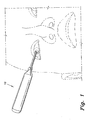
- the intraocular lens fixation device (hereinafter referred to as an IOL fixation device), a first embodiment of which is generally referred to by the reference number 10, provides precise alignment positioning of an IOL with minimal risk to the lens capsule or capsular bag, and with minimum human error.
- the IOL fixation device 10 includes a housing having an elongate handle 12 that tapers at one end to an elongate neck 14.
- the handle 12 is preferably dimensioned to fit comfortably in the user's hand.
- the handle 12 can be gnarled, can have protrusions of various shapes, can be striated, can be covered or coated with friction-enhancing material, or can otherwise be configured to enhance grip.
- the neck 14 is preferably slender or of much smaller width or diameter than the handle 12 so that the distal end of the neck 14 can be easily manipulated during surgery.
- the distal end of the neck 14 includes a head section 16, from which precise and accurate alignment of the IOL can be made.
- the handle 12 and neck 14 are substantially hollow.
- the head section 16 houses a rotator 20.
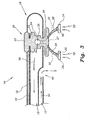
- the rotator 20 is preferably a single-piece unit having, from the top down in Fig. 3 , a pulley wheel 22, a central support 24, and a circular disc or flange 26 extending below the bottom of the head section 16.
- One end of a cable 18 is trained around a circular groove 23 formed in the pulley wheel 22, and the other end of the cable 18 is operatively attached to a motor 19 (shown in Fig. 2 ).
- a power cord 11 provides power to the motor 19.
- Selective activation of the motor 19 rotates the rotator 20 through the interaction of the cable 18 rotating the pulley wheel 22.
- the motor 19 is preferably reversible so that the rotator 20 can be rotated in the opposite direction, if required or desired by the user. Additionally, the motor 19 can be an electric or pneumatic type motor.
- the central support 24 is preferably a cylindrical segment interconnected to the pulley wheel 22 and the flange 26.
- the central support 24 includes a throughbore or opening 25 communicating with a hollow vacuum passage 27 extending into the flange 26.
- a plurality of vacuum holding legs 30 extend radially from the flange 26, and a suction cup 34 is attached to the distal end of each leg 30.
- the suction cups 34 are configured to gently but firmly hold onto the IOL TI via vacuum.
- the IOL fixation device 10 may, e.g., have four holding legs 30 that include two pairs of legs symmetrically spaced about the flange 26. The legs 30 of each pair are angularly spaced at an acute angle. The mid-angle of each pair defines a virtual axis therebetween.
- the top of the pulley wheel 22, which is exposed on top of the head section 16, includes an alignment marker or indicia 21.
- the alignment marker 21 is preferably a straight line or other similar indicia formed by a groove, etching, paint, or the like. This line is aligned with the virtual axis between each pair of holding legs 30.
- the arrangement of the holding legs 30 and the alignment marker 21 provides a visual guide for the user, so that the user can properly align the IOL fixation device 10 with corresponding alignment markers AM, e.g., dots, on the toric IOL TI as shown in Fig. 4 .
- the holding legs 30 are preferably constructed from flexible PMMA (polymethylmethacrylate), which is an inert form of biocompatible plastic safe for use in surgical environments. Other similar plastics can also be used.
- Each leg 30 is hollow and includes a channel 32 communicating with the vacuum passage 27.
- each suction cup 34 includes a hollow channel 36 communicating with the channel 32 in the corresponding leg 30.
- the suction cups 34 are preferably constructed from soft silicon that can safely hold the IOL TI without damaging the same.
- the vacuum is supplied from an exterior remote source via the vacuum line 15 and the vacuum chamber 13 inside the housing. It is noted that relevant parts of the housing are sealed to insure vacuum operation.
- the IOL fixation device 10 also includes an irrigation channel 17 inside the housing communicating with an irrigation outlet or hole 40.
- the irrigation outlet 40 is preferably disposed proximate to, or a relatively short distance away from, the holding legs 30, as shown in Figs. 3 and 5 .
- This arrangement allows the user to apply irrigation fluid in situ, rather than having to re-manipulate the IOL fixation device 10 or to use a separate, remote irrigation tool. Such measures minimize potential widening of the initial incision or rupture of the lens capsule.
- the application of the irrigation fluid can be facilitated by a syringe mechanism 42 having an interior source of fluid (not shown) or a rear connection to a remote pump and source of fluid.
- the toric IOL TI is inserted into the eye through a small incision in the usual manner, after removal of the impaired lens.
- An axis alignment marker based on preoperative IOL calculations and measurements is marked or placed over the eye.
- the rotator 20 Prior to insertion of the IOL fixation tool 10, the rotator 20 is rotated via selective activation of a button 44 to operate a motor that aligns the alignment marker 21 with the alignment markers AM on the IOL TI.
- the head section 16 is carefully inserted through the incision until the head section 16 overlies the IOL TI. Centering is performed through readjustment, as needed. Once centered, vacuum is activated to commence negative airflow, as indicated by the arrows 50 in Fig. 3 .
- the rotator 20 is again activated to gently rotate the IOL TI into the proper position outlined by the axis alignment marker. Once the IOL TI is properly placed, vacuum is deactivated, and the IOL fixation device 10 is gently removed from the eye.
- the IOL fixation device 10 substantially minimizes some of the more common human errors that can occur. Throughout the above procedure, there is minimal maneuvering of the IOL fixation device 10. The major manipulation of the IOL fixation device 10 occurs mainly in the insertion and extraction of the head section 16. Meanwhile, the rotator 20 and the suction cups 34 perform the rotation for alignment, while the IOL fixation device 10 is stationary. Thus, manual rotation is eliminated. This also eliminates some of the potential rupturing of the lens capsule due to inadvertent and overt manipulation of a surgical tool by the surgeon. Moreover, a majority of the delicate and stressful repetitious handling of the conventional forceps type devices are eliminated thereby.
- the above IOL fixation device 10 is an example of an automatic microsurgical tool.
- the selective activation of the rotator 20 is facilitated by the button 44.
- the button 44 can be configured or pre-programmed with various functions. For example, a combination of button presses can be used to rotate the rotator 20 in opposite directions, or to operate the vacuum.
- Fig. 6 discloses an alternative embodiment of an IOL fixation device 100.
- This IOL fixation device 100 is an example of a manual microsurgical tool, which eliminates the motor, power cord and button operation.
- the IOL fixation device 100 includes a manual dial 144 having the pulley cable 18 operatively attached thereto. The user rotates the dial 144 to rotate the rotator 20.
- the IOL fixation device 100 operates and functions substantially the same as the IOL fixation device 10.
- the IOL fixation device 10, 100 encompasses a variety of alternatives.
- the IOL fixation device 10, 100 can be constructed from surgical grade plastics, metals, composites and/or combinations thereof.
- the IOL fixation device 10, 100 can also include selectively operable LED lights for illuminating target areas during surgery.
- the IOL fixation device 10, 100 can also be operatively connected to precision imaging and adjusting devices, such microscopes and computers, to assist alignment procedures.
Landscapes
- Health & Medical Sciences (AREA)
- Ophthalmology & Optometry (AREA)
- Cardiology (AREA)
- Oral & Maxillofacial Surgery (AREA)
- Transplantation (AREA)
- Engineering & Computer Science (AREA)
- Biomedical Technology (AREA)
- Heart & Thoracic Surgery (AREA)
- Vascular Medicine (AREA)
- Life Sciences & Earth Sciences (AREA)
- Animal Behavior & Ethology (AREA)
- General Health & Medical Sciences (AREA)
- Public Health (AREA)
- Veterinary Medicine (AREA)
- Prostheses (AREA)
Claims (12)
- Dispositif de fixation de lentille intraoculaire (LIO), comprenant :un logement creux ayant un manche allongé (12) et une tige allongée (14) s'étendant à partir du manche, la tige ayant une largeur inférieure à celle du manche, le logement ayant une chambre à vide intérieure,une tête (16) disposée au niveau de l'extrémité de la tige distale du manche ;une source de vide (15) sélectivement actionnable opérationnellement fixée au logement ; etun moyen d'irrigation (17) pour irriguer l'oeil et maintenir la profondeur de la chambre antérieure d'une capsule de cristallin pendant une opération d'implantation de lentille intraoculaire ; caractérisé parun rotateur (20) reçu dans la tête, le rotateur pouvant sélectivement pivoter, le rotateur ayant une pluralité de pattes de maintien à vide (30) s'étendant radialement à partir de celui-ci, chacune des pattes ayant une extrémité distale et une ventouse (34) fixée à l'extrémité distale de la patte ; etdans lequel l'activation sélective de la source de vide facilite la préhension douce et ferme de la LIO par les ventouses, et la rotation sélective du rotateur aligne par rotation la LIO dans une position correcte souhaitée durant l'opération d'implantation avec un repositionnement moindre du dispositif de fixation de la LIO.
- Dispositif de fixation de LIO selon la revendication 1, dans lequel ledit rotateur comprend :une poulie ayant une face supérieure exposée sur le dessus de la tête, la poule ayant une reinure pour câble circulaire ;un support central fixé à la pulie, le support central ayant une ouverture communiquant avec ladite chambre à vide ; etun rebord s'étendant à partir du support central, ladite pluralité de pattes de maintien s'étendant à partir du rebord, le rebord ayant un passage à vide intérieur communiquant avec l'ouverture dans le support central.
- Dispositif de fixation de LIO selon la revendication 2, dans lequel ladite pluralité de pattes de maintien comprend quatre pattes de maintien à vide, chacune des pattes de maintien à vide ayant un canal creux intérieur, chacune desdites ventouses ayant un canal intérieur, le canal de chacune desdites pattes ayant une extrémité communiquant avec le passage à vide dans ledit rebord et une extrémité opposée communiquant avec le canal intérieur correspondant dans ladite ventouse, les canaux desdites pattes et desdites ventouses facilitant le flux de vide lors de son activation.
- Dispositif de fixation de LIO selon la revendication 3, dans lequel lesdites quatre pattes de maintien à vide comprennent deux paires espacées symétriquement et angulairement autour dudit rebord, chaque paire desdites pattes définissant un angle aigu, les angles aigus étant des angles opposés définissant un axe virtuel entre eux.
- Dispositif de fixation de LIO selon la revendication 4, dans lequel sur la face supérieure de ladite poulie est disposé un repère d'alignement, le repère d'alignement pouvant être aligné sur l'axe virtuel, le repère d'alignement formant une aide visuelle pour aligner lesdites pattes de maintien sur les repères d'alignement sur ladite LIO.
- Dispositif de fixation de LIO selon la revendication 2, comprenant en outre :un câble ayant une extrémité entraînée autour de la rainure pour câble sur ladite poulie ; etun actionneur pour la rotation sélective dudit rotateur, le câble ayant une extrémité opposée opérationnellement fixée à l'actionneur.
- Dispositif de fixation de LIO selon la revendication 6, dans lequel ledit actionneur comprend un moteur disposé dans ledit logement et un bouton disposé sur le logement et raccordé au moteur pour l'activation sélective du moteur.
- Dispositif de fixation de LIO selon la revendication 6, dans lequel ledit actionneur comprend un cadran manuel.
- Dispositif de fixation de LIO selon la revendication 1, dans lequel ledit moyen d'irrigation comprend un canal d'irrigation disposé dans ledit logement ; un orifice de sortie d'irrigation au niveau d'une extrémité du canal d'irrigation ; et une seringue d'irrigation raccordée au canal d'irrigation à l'opposé de l'extrémité d'orifice de sortie.
- Dispositif de fixation de LIO selon la revendication 9, dans lequel ledit orifice de sortie d'irrigation est disposé à proximité desdites pattes de maintien à vide.
- Dispositif de fixation de LIO selon la revendication 1, dans lequel lesdites pattes de maintien à vide sont fabriquées en polyméthacrylate de méthyle(PMMA) souple.
- Dispositif de fixation de LIO selon la revendication 1, dans lequel lesdites ventouses sont fabriquées en silicium souple.
Applications Claiming Priority (1)
| Application Number | Priority Date | Filing Date | Title |
|---|---|---|---|
| US13/603,244 US8419790B1 (en) | 2012-09-04 | 2012-09-04 | Intraocular lens fixation device |
Publications (2)
| Publication Number | Publication Date |
|---|---|
| EP2702961A1 EP2702961A1 (fr) | 2014-03-05 |
| EP2702961B1 true EP2702961B1 (fr) | 2014-12-17 |
Family
ID=48049101
Family Applications (1)
| Application Number | Title | Priority Date | Filing Date |
|---|---|---|---|
| EP13180171.4A Not-in-force EP2702961B1 (fr) | 2012-09-04 | 2013-08-13 | Dispositif de fixation de lentille intraoculaire |
Country Status (2)
| Country | Link |
|---|---|
| US (1) | US8419790B1 (fr) |
| EP (1) | EP2702961B1 (fr) |
Families Citing this family (12)
| Publication number | Priority date | Publication date | Assignee | Title |
|---|---|---|---|---|
| US9788938B2 (en) * | 2011-10-05 | 2017-10-17 | The Regents Of The University Of Colorado, A Body Corporate | Intraocular manipulator and related methods |
| EP2602099B1 (fr) * | 2011-12-08 | 2014-02-12 | Harro Höfliger Verpackungsmaschinen GmbH | Pince aspirante et système de manipulation pour lentilles de contact |
| CA3005338A1 (fr) | 2015-11-18 | 2017-05-26 | Shifamed Holdings, Llc | Lentille intraoculaire accommodative multi-pieces |
| EP3634309B1 (fr) | 2017-06-07 | 2023-05-24 | Shifamed Holdings, LLC | Lentilles intraoculaires à puissance optique réglable |
| WO2019209967A1 (fr) * | 2018-04-25 | 2019-10-31 | The Regents Of The University Of California | Évaluation peropératoire de positionnement d'implant |
| CN109350353B (zh) * | 2018-10-18 | 2023-10-17 | 溧阳市中医医院 | 中央孔型人工晶体植入术用后房粘弹剂的吸除装置及用法 |
| KR102188950B1 (ko) * | 2019-04-09 | 2020-12-09 | 정영택 | 관류액이 공급되는 안과 수술용 도구 |
| US12521232B2 (en) | 2019-07-11 | 2026-01-13 | Shifamed Holdings, Llc | Accommodating intraocular lenses and associated methods |
| CN110236785A (zh) * | 2019-07-15 | 2019-09-17 | 温州医科大学附属眼视光医院 | 一种负压吸引式人工晶状体挑拨器 |
| US20220151770A1 (en) * | 2020-11-16 | 2022-05-19 | The Regents Of The University Of California | Suction-based tool for positioning intraocular implants |
| CN113040761B (zh) * | 2021-03-08 | 2023-05-16 | 杭州微策生物技术股份有限公司 | 一种吸附旋钮助针器 |
| WO2025080591A1 (fr) * | 2023-10-09 | 2025-04-17 | Shifamed Holdings, Llc | Systèmes et procédés de fabrication de lentilles intraoculaires de réception |
Family Cites Families (12)
| Publication number | Priority date | Publication date | Assignee | Title |
|---|---|---|---|---|
| US4047532A (en) * | 1975-04-21 | 1977-09-13 | Phillips Jack L | Vacuum forcep and method of using same |
| US4332408A (en) | 1978-10-12 | 1982-06-01 | Cointment Delma M | Device for removing and replacing soft contact lenses worn on the human eye |
| US4406285A (en) | 1981-01-23 | 1983-09-27 | Richard A. Villasenor | Manual radial and chordal keratotometry apparatus |
| US4688570A (en) | 1981-03-09 | 1987-08-25 | The Regents Of The University Of California | Ophthalmologic surgical instrument |
| US5836311A (en) * | 1995-09-20 | 1998-11-17 | Medtronic, Inc. | Method and apparatus for temporarily immobilizing a local area of tissue |
| US6338712B2 (en) * | 1997-09-17 | 2002-01-15 | Origin Medsystems, Inc. | Device to permit offpump beating heart coronary bypass surgery |
| US6599305B1 (en) | 1998-08-12 | 2003-07-29 | Vladimir Feingold | Intracorneal lens placement method and apparatus |
| US6273894B1 (en) | 1999-07-22 | 2001-08-14 | Staar Surgical Company, Inc. | Vacuum cannula apparatus and method for positioning an intraocular lens in the eye |
| US6506149B2 (en) * | 1999-09-07 | 2003-01-14 | Origin Medsystems, Inc. | Organ manipulator having suction member supported with freedom to move relative to its support |
| US6596000B2 (en) | 1999-11-05 | 2003-07-22 | Alcon Universal Ltd. | Instrument for positioning an intracorneal optical lens |
| CN102026600B (zh) | 2008-05-15 | 2013-12-11 | 脉诺斯细胞器械公司 | 用于囊切开术的眼外科手术设备 |
| JP5719022B2 (ja) | 2010-06-07 | 2015-05-13 | ミノシス セルラー デバイシズ インコーポレイテッド | 組織に到達し、嚢切開を実施するための眼科用の外科デバイス |
-
2012
- 2012-09-04 US US13/603,244 patent/US8419790B1/en not_active Expired - Fee Related
-
2013
- 2013-08-13 EP EP13180171.4A patent/EP2702961B1/fr not_active Not-in-force
Also Published As
| Publication number | Publication date |
|---|---|
| US8419790B1 (en) | 2013-04-16 |
| EP2702961A1 (fr) | 2014-03-05 |
Similar Documents
| Publication | Publication Date | Title |
|---|---|---|
| EP2702961B1 (fr) | Dispositif de fixation de lentille intraoculaire | |
| US20250295522A1 (en) | Method and apparatus for suprachoroidal administration of therapeutic agent | |
| CN103313751B (zh) | 眼内分流器展开装置 | |
| US8632589B2 (en) | IOL insertion system with semi-automatic trailing haptic configuration management | |
| US9795504B2 (en) | Eye fixation system for posterior and anterior segment eye surgery and procedures | |
| US11684511B2 (en) | Irrigation and aspiration sleeve for phacoemulsification | |
| US6143010A (en) | Corneal vacuum centering device | |
| US20190357768A1 (en) | Glaucoma Surgery Visualization Apparatus | |
| US5192293A (en) | Drill guide for orbital implant | |
| CA3061886A1 (fr) | Canule d'entree avec joint active par pression intraoculaire | |
| WO2013052578A2 (fr) | Manipulateur intraoculaire et procédés associés | |
| CN102596122A (zh) | 用于眼科手术的眼睛标记器 | |
| US20070083221A1 (en) | Precision trephine | |
| US20190167415A1 (en) | Surgical tool and method | |
| Waring et al. | The Hanna suction punch block and trephine system for penetrating keratoplasty | |
| ES2983184T3 (es) | Dispositivo para cirugía vitreorretiniana | |
| US7951136B2 (en) | Coupler wrench | |
| US12343290B2 (en) | Ophthalmic incisional procedure instrument and method | |
| WO2019195908A1 (fr) | Instrument pour chirurgie de cataracte | |
| ES3004612T3 (en) | Ophthalmological hand-held device | |
| HK40062697A (en) | Method and apparatus for suprachoroidal administration of therapeutic agent | |
| JP2026502696A (ja) | 眼科用切開処置器具および方法 | |
| AU738022B2 (en) | Opthamological instruments and methods of use | |
| HK40047835A (en) | Apparatus for suprachoroidal administration of therapeutic agent | |
| Keratomileusis et al. | StJ. rgical Instruments and Equipment |
Legal Events
| Date | Code | Title | Description |
|---|---|---|---|
| AK | Designated contracting states |
Kind code of ref document: A1 Designated state(s): AL AT BE BG CH CY CZ DE DK EE ES FI FR GB GR HR HU IE IS IT LI LT LU LV MC MK MT NL NO PL PT RO RS SE SI SK SM TR |
|
| AX | Request for extension of the european patent |
Extension state: BA ME |
|
| PUAI | Public reference made under article 153(3) epc to a published international application that has entered the european phase |
Free format text: ORIGINAL CODE: 0009012 |
|
| 17P | Request for examination filed |
Effective date: 20140326 |
|
| RBV | Designated contracting states (corrected) |
Designated state(s): AL AT BE BG CH CY CZ DE DK EE ES FI FR GB GR HR HU IE IS IT LI LT LU LV MC MK MT NL NO PL PT RO RS SE SI SK SM TR |
|
| RIC1 | Information provided on ipc code assigned before grant |
Ipc: A61F 2/16 20060101AFI20140414BHEP |
|
| GRAP | Despatch of communication of intention to grant a patent |
Free format text: ORIGINAL CODE: EPIDOSNIGR1 |
|
| INTG | Intention to grant announced |
Effective date: 20140625 |
|
| GRAS | Grant fee paid |
Free format text: ORIGINAL CODE: EPIDOSNIGR3 |
|
| GRAA | (expected) grant |
Free format text: ORIGINAL CODE: 0009210 |
|
| AK | Designated contracting states |
Kind code of ref document: B1 Designated state(s): AL AT BE BG CH CY CZ DE DK EE ES FI FR GB GR HR HU IE IS IT LI LT LU LV MC MK MT NL NO PL PT RO RS SE SI SK SM TR |
|
| REG | Reference to a national code |
Ref country code: GB Ref legal event code: FG4D |
|
| REG | Reference to a national code |
Ref country code: CH Ref legal event code: EP |
|
| REG | Reference to a national code |
Ref country code: IE Ref legal event code: FG4D |
|
| REG | Reference to a national code |
Ref country code: AT Ref legal event code: REF Ref document number: 701309 Country of ref document: AT Kind code of ref document: T Effective date: 20150115 |
|
| REG | Reference to a national code |
Ref country code: DE Ref legal event code: R096 Ref document number: 602013000647 Country of ref document: DE Effective date: 20150205 |
|
| PG25 | Lapsed in a contracting state [announced via postgrant information from national office to epo] |
Ref country code: NO Free format text: LAPSE BECAUSE OF FAILURE TO SUBMIT A TRANSLATION OF THE DESCRIPTION OR TO PAY THE FEE WITHIN THE PRESCRIBED TIME-LIMIT Effective date: 20150317 Ref country code: FI Free format text: LAPSE BECAUSE OF FAILURE TO SUBMIT A TRANSLATION OF THE DESCRIPTION OR TO PAY THE FEE WITHIN THE PRESCRIBED TIME-LIMIT Effective date: 20141217 Ref country code: LT Free format text: LAPSE BECAUSE OF FAILURE TO SUBMIT A TRANSLATION OF THE DESCRIPTION OR TO PAY THE FEE WITHIN THE PRESCRIBED TIME-LIMIT Effective date: 20141217 |
|
| REG | Reference to a national code |
Ref country code: LT Ref legal event code: MG4D |
|
| PG25 | Lapsed in a contracting state [announced via postgrant information from national office to epo] |
Ref country code: LV Free format text: LAPSE BECAUSE OF FAILURE TO SUBMIT A TRANSLATION OF THE DESCRIPTION OR TO PAY THE FEE WITHIN THE PRESCRIBED TIME-LIMIT Effective date: 20141217 Ref country code: RS Free format text: LAPSE BECAUSE OF FAILURE TO SUBMIT A TRANSLATION OF THE DESCRIPTION OR TO PAY THE FEE WITHIN THE PRESCRIBED TIME-LIMIT Effective date: 20141217 Ref country code: GR Free format text: LAPSE BECAUSE OF FAILURE TO SUBMIT A TRANSLATION OF THE DESCRIPTION OR TO PAY THE FEE WITHIN THE PRESCRIBED TIME-LIMIT Effective date: 20150318 Ref country code: HR Free format text: LAPSE BECAUSE OF FAILURE TO SUBMIT A TRANSLATION OF THE DESCRIPTION OR TO PAY THE FEE WITHIN THE PRESCRIBED TIME-LIMIT Effective date: 20141217 Ref country code: SE Free format text: LAPSE BECAUSE OF FAILURE TO SUBMIT A TRANSLATION OF THE DESCRIPTION OR TO PAY THE FEE WITHIN THE PRESCRIBED TIME-LIMIT Effective date: 20141217 |
|
| REG | Reference to a national code |
Ref country code: AT Ref legal event code: MK05 Ref document number: 701309 Country of ref document: AT Kind code of ref document: T Effective date: 20141217 |
|
| PG25 | Lapsed in a contracting state [announced via postgrant information from national office to epo] |
Ref country code: NL Free format text: LAPSE BECAUSE OF FAILURE TO SUBMIT A TRANSLATION OF THE DESCRIPTION OR TO PAY THE FEE WITHIN THE PRESCRIBED TIME-LIMIT Effective date: 20141217 |
|
| PG25 | Lapsed in a contracting state [announced via postgrant information from national office to epo] |
Ref country code: ES Free format text: LAPSE BECAUSE OF FAILURE TO SUBMIT A TRANSLATION OF THE DESCRIPTION OR TO PAY THE FEE WITHIN THE PRESCRIBED TIME-LIMIT Effective date: 20141217 Ref country code: CZ Free format text: LAPSE BECAUSE OF FAILURE TO SUBMIT A TRANSLATION OF THE DESCRIPTION OR TO PAY THE FEE WITHIN THE PRESCRIBED TIME-LIMIT Effective date: 20141217 Ref country code: SK Free format text: LAPSE BECAUSE OF FAILURE TO SUBMIT A TRANSLATION OF THE DESCRIPTION OR TO PAY THE FEE WITHIN THE PRESCRIBED TIME-LIMIT Effective date: 20141217 Ref country code: RO Free format text: LAPSE BECAUSE OF FAILURE TO SUBMIT A TRANSLATION OF THE DESCRIPTION OR TO PAY THE FEE WITHIN THE PRESCRIBED TIME-LIMIT Effective date: 20141217 Ref country code: EE Free format text: LAPSE BECAUSE OF FAILURE TO SUBMIT A TRANSLATION OF THE DESCRIPTION OR TO PAY THE FEE WITHIN THE PRESCRIBED TIME-LIMIT Effective date: 20141217 Ref country code: PT Free format text: LAPSE BECAUSE OF FAILURE TO SUBMIT A TRANSLATION OF THE DESCRIPTION OR TO PAY THE FEE WITHIN THE PRESCRIBED TIME-LIMIT Effective date: 20150417 |
|
| PG25 | Lapsed in a contracting state [announced via postgrant information from national office to epo] |
Ref country code: PL Free format text: LAPSE BECAUSE OF FAILURE TO SUBMIT A TRANSLATION OF THE DESCRIPTION OR TO PAY THE FEE WITHIN THE PRESCRIBED TIME-LIMIT Effective date: 20141217 Ref country code: IS Free format text: LAPSE BECAUSE OF FAILURE TO SUBMIT A TRANSLATION OF THE DESCRIPTION OR TO PAY THE FEE WITHIN THE PRESCRIBED TIME-LIMIT Effective date: 20150417 Ref country code: AT Free format text: LAPSE BECAUSE OF FAILURE TO SUBMIT A TRANSLATION OF THE DESCRIPTION OR TO PAY THE FEE WITHIN THE PRESCRIBED TIME-LIMIT Effective date: 20141217 |
|
| REG | Reference to a national code |
Ref country code: DE Ref legal event code: R097 Ref document number: 602013000647 Country of ref document: DE |
|
| PLBE | No opposition filed within time limit |
Free format text: ORIGINAL CODE: 0009261 |
|
| STAA | Information on the status of an ep patent application or granted ep patent |
Free format text: STATUS: NO OPPOSITION FILED WITHIN TIME LIMIT |
|
| PG25 | Lapsed in a contracting state [announced via postgrant information from national office to epo] |
Ref country code: DK Free format text: LAPSE BECAUSE OF FAILURE TO SUBMIT A TRANSLATION OF THE DESCRIPTION OR TO PAY THE FEE WITHIN THE PRESCRIBED TIME-LIMIT Effective date: 20141217 |
|
| 26N | No opposition filed |
Effective date: 20150918 |
|
| PG25 | Lapsed in a contracting state [announced via postgrant information from national office to epo] |
Ref country code: IT Free format text: LAPSE BECAUSE OF FAILURE TO SUBMIT A TRANSLATION OF THE DESCRIPTION OR TO PAY THE FEE WITHIN THE PRESCRIBED TIME-LIMIT Effective date: 20141217 |
|
| PG25 | Lapsed in a contracting state [announced via postgrant information from national office to epo] |
Ref country code: SI Free format text: LAPSE BECAUSE OF FAILURE TO SUBMIT A TRANSLATION OF THE DESCRIPTION OR TO PAY THE FEE WITHIN THE PRESCRIBED TIME-LIMIT Effective date: 20141217 |
|
| PG25 | Lapsed in a contracting state [announced via postgrant information from national office to epo] |
Ref country code: LU Free format text: LAPSE BECAUSE OF FAILURE TO SUBMIT A TRANSLATION OF THE DESCRIPTION OR TO PAY THE FEE WITHIN THE PRESCRIBED TIME-LIMIT Effective date: 20150813 Ref country code: MC Free format text: LAPSE BECAUSE OF FAILURE TO SUBMIT A TRANSLATION OF THE DESCRIPTION OR TO PAY THE FEE WITHIN THE PRESCRIBED TIME-LIMIT Effective date: 20141217 |
|
| PG25 | Lapsed in a contracting state [announced via postgrant information from national office to epo] |
Ref country code: BE Free format text: LAPSE BECAUSE OF FAILURE TO SUBMIT A TRANSLATION OF THE DESCRIPTION OR TO PAY THE FEE WITHIN THE PRESCRIBED TIME-LIMIT Effective date: 20141217 |
|
| REG | Reference to a national code |
Ref country code: IE Ref legal event code: MM4A |
|
| REG | Reference to a national code |
Ref country code: FR Ref legal event code: ST Effective date: 20160429 |
|
| PG25 | Lapsed in a contracting state [announced via postgrant information from national office to epo] |
Ref country code: IE Free format text: LAPSE BECAUSE OF NON-PAYMENT OF DUE FEES Effective date: 20150813 |
|
| PG25 | Lapsed in a contracting state [announced via postgrant information from national office to epo] |
Ref country code: FR Free format text: LAPSE BECAUSE OF NON-PAYMENT OF DUE FEES Effective date: 20150831 |
|
| PG25 | Lapsed in a contracting state [announced via postgrant information from national office to epo] |
Ref country code: MT Free format text: LAPSE BECAUSE OF FAILURE TO SUBMIT A TRANSLATION OF THE DESCRIPTION OR TO PAY THE FEE WITHIN THE PRESCRIBED TIME-LIMIT Effective date: 20141217 |
|
| REG | Reference to a national code |
Ref country code: CH Ref legal event code: PL |
|
| PG25 | Lapsed in a contracting state [announced via postgrant information from national office to epo] |
Ref country code: LI Free format text: LAPSE BECAUSE OF NON-PAYMENT OF DUE FEES Effective date: 20160831 Ref country code: CH Free format text: LAPSE BECAUSE OF NON-PAYMENT OF DUE FEES Effective date: 20160831 |
|
| PG25 | Lapsed in a contracting state [announced via postgrant information from national office to epo] |
Ref country code: HU Free format text: LAPSE BECAUSE OF FAILURE TO SUBMIT A TRANSLATION OF THE DESCRIPTION OR TO PAY THE FEE WITHIN THE PRESCRIBED TIME-LIMIT; INVALID AB INITIO Effective date: 20130813 Ref country code: BG Free format text: LAPSE BECAUSE OF FAILURE TO SUBMIT A TRANSLATION OF THE DESCRIPTION OR TO PAY THE FEE WITHIN THE PRESCRIBED TIME-LIMIT Effective date: 20141217 |
|
| PG25 | Lapsed in a contracting state [announced via postgrant information from national office to epo] |
Ref country code: CY Free format text: LAPSE BECAUSE OF FAILURE TO SUBMIT A TRANSLATION OF THE DESCRIPTION OR TO PAY THE FEE WITHIN THE PRESCRIBED TIME-LIMIT Effective date: 20141217 |
|
| PG25 | Lapsed in a contracting state [announced via postgrant information from national office to epo] |
Ref country code: SM Free format text: LAPSE BECAUSE OF FAILURE TO SUBMIT A TRANSLATION OF THE DESCRIPTION OR TO PAY THE FEE WITHIN THE PRESCRIBED TIME-LIMIT Effective date: 20141217 |
|
| PG25 | Lapsed in a contracting state [announced via postgrant information from national office to epo] |
Ref country code: MK Free format text: LAPSE BECAUSE OF FAILURE TO SUBMIT A TRANSLATION OF THE DESCRIPTION OR TO PAY THE FEE WITHIN THE PRESCRIBED TIME-LIMIT Effective date: 20141217 Ref country code: TR Free format text: LAPSE BECAUSE OF FAILURE TO SUBMIT A TRANSLATION OF THE DESCRIPTION OR TO PAY THE FEE WITHIN THE PRESCRIBED TIME-LIMIT Effective date: 20141217 |
|
| PG25 | Lapsed in a contracting state [announced via postgrant information from national office to epo] |
Ref country code: AL Free format text: LAPSE BECAUSE OF FAILURE TO SUBMIT A TRANSLATION OF THE DESCRIPTION OR TO PAY THE FEE WITHIN THE PRESCRIBED TIME-LIMIT Effective date: 20141217 |
|
| PGFP | Annual fee paid to national office [announced via postgrant information from national office to epo] |
Ref country code: DE Payment date: 20190903 Year of fee payment: 7 |
|
| PGFP | Annual fee paid to national office [announced via postgrant information from national office to epo] |
Ref country code: GB Payment date: 20190904 Year of fee payment: 7 |
|
| REG | Reference to a national code |
Ref country code: DE Ref legal event code: R119 Ref document number: 602013000647 Country of ref document: DE |
|
| GBPC | Gb: european patent ceased through non-payment of renewal fee |
Effective date: 20200813 |
|
| PG25 | Lapsed in a contracting state [announced via postgrant information from national office to epo] |
Ref country code: DE Free format text: LAPSE BECAUSE OF NON-PAYMENT OF DUE FEES Effective date: 20210302 |
|
| PG25 | Lapsed in a contracting state [announced via postgrant information from national office to epo] |
Ref country code: GB Free format text: LAPSE BECAUSE OF NON-PAYMENT OF DUE FEES Effective date: 20200813 |