EP2703012B1 - Dispositif et procédé destinés à la désinfection de récipients - Google Patents
Dispositif et procédé destinés à la désinfection de récipients Download PDFInfo
- Publication number
- EP2703012B1 EP2703012B1 EP13003888.8A EP13003888A EP2703012B1 EP 2703012 B1 EP2703012 B1 EP 2703012B1 EP 13003888 A EP13003888 A EP 13003888A EP 2703012 B1 EP2703012 B1 EP 2703012B1
- Authority
- EP
- European Patent Office
- Prior art keywords
- housing
- ozone
- container
- generating unit
- openings
- Prior art date
- Legal status (The legal status is an assumption and is not a legal conclusion. Google has not performed a legal analysis and makes no representation as to the accuracy of the status listed.)
- Active
Links
Images




Classifications
-
- A—HUMAN NECESSITIES
- A61—MEDICAL OR VETERINARY SCIENCE; HYGIENE
- A61L—METHODS OR APPARATUS FOR STERILISING MATERIALS OR OBJECTS IN GENERAL; DISINFECTION, STERILISATION OR DEODORISATION OF AIR; CHEMICAL ASPECTS OF BANDAGES, DRESSINGS, ABSORBENT PADS OR SURGICAL ARTICLES; MATERIALS FOR BANDAGES, DRESSINGS, ABSORBENT PADS OR SURGICAL ARTICLES
- A61L2/00—Disinfection or sterilisation of materials or objects, in general; Accessories therefor
- A61L2/16—Disinfection or sterilisation of materials or objects, in general; Accessories therefor using chemical substances
- A61L2/20—Gaseous substances, e.g. vapours
- A61L2/202—Ozone
-
- A—HUMAN NECESSITIES
- A61—MEDICAL OR VETERINARY SCIENCE; HYGIENE
- A61L—METHODS OR APPARATUS FOR STERILISING MATERIALS OR OBJECTS IN GENERAL; DISINFECTION, STERILISATION OR DEODORISATION OF AIR; CHEMICAL ASPECTS OF BANDAGES, DRESSINGS, ABSORBENT PADS OR SURGICAL ARTICLES; MATERIALS FOR BANDAGES, DRESSINGS, ABSORBENT PADS OR SURGICAL ARTICLES
- A61L2/00—Disinfection or sterilisation of materials or objects, in general; Accessories therefor
- A61L2/02—Disinfection or sterilisation of materials or objects, in general; Accessories therefor using physical processes
- A61L2/14—Plasma, i.e. ionised gases
-
- A—HUMAN NECESSITIES
- A61—MEDICAL OR VETERINARY SCIENCE; HYGIENE
- A61L—METHODS OR APPARATUS FOR STERILISING MATERIALS OR OBJECTS IN GENERAL; DISINFECTION, STERILISATION OR DEODORISATION OF AIR; CHEMICAL ASPECTS OF BANDAGES, DRESSINGS, ABSORBENT PADS OR SURGICAL ARTICLES; MATERIALS FOR BANDAGES, DRESSINGS, ABSORBENT PADS OR SURGICAL ARTICLES
- A61L2103/00—Materials or objects being the target of disinfection or sterilisation
- A61L2103/23—Containers other than laboratory or medical, e.g. bottles or mail
-
- B—PERFORMING OPERATIONS; TRANSPORTING
- B08—CLEANING
- B08B—CLEANING IN GENERAL; PREVENTION OF FOULING IN GENERAL
- B08B2203/00—Details of cleaning machines or methods involving the use or presence of liquid or steam
- B08B2203/005—Details of cleaning machines or methods involving the use or presence of liquid or steam the liquid being ozonated
-
- B—PERFORMING OPERATIONS; TRANSPORTING
- B08—CLEANING
- B08B—CLEANING IN GENERAL; PREVENTION OF FOULING IN GENERAL
- B08B9/00—Cleaning hollow articles by methods or apparatus specially adapted thereto
- B08B9/08—Cleaning containers, e.g. tanks
- B08B9/0804—Cleaning containers having tubular shape, e.g. casks, barrels, drums
Definitions
- the present invention relates to a device for disinfecting an interior of a container. Furthermore, the present invention relates to a method for disinfecting the interior of wooden containers.
- the disinfection of containers in particular in the food industry is generally carried out by disinfection with liquids and possibly by additional mechanical treatment.
- sulfur dioxide gas has always been used in the disinfection of wooden barrels.
- Sulfur chippings within a wooden barrel burned or verkokelt e.g. Sulfur chippings within a wooden barrel burned or verkokelt.
- the biocidal effect of sulfur dioxide and the sulfites is based in particular on their reduction effect.
- the available oxygen is rapidly absorbed by sulfur dioxide and by the sulfites, so that aerobic organisms are prevented in their metabolism and thus die off.
- the biocidal effect against anaerobic microorganisms, however, is poor.
- German patent application DE 35 02 242 A1 is a process for sterilizing drums, in which ozone gas or ozone water is introduced into the barrels.
- the present invention has for its object to provide an apparatus and a method that allow disinfection of containers and in particular of wood barrels, without requiring a complex mechanical cleaning or post-cleaning is necessary and in particular without residues remain in the containers that lead to a burden on food, which can have a negative impact on the health of consumers of food. Furthermore, it should be the Disinfecting effect over the known methods not deteriorated and preferably even improved.
- in the region of the first or second end refers to the portion of the housing that corresponds to one-half, preferably one-third, of the housing facing the respective end.
- Ozone for use as a disinfectant has the advantage that both aerobic and anaerobic microorganisms are equally completely killed. As a result, even at pH values around 7, ie in a neutral environment, killing rates can be achieved which leave no demonstrable residual germ content. Ozone penetrates as gas into every corner of the container and can even penetrate into the wood when used in wooden containers and thus lead to an optimal disinfection of the entire container. Besides, by the ozone generating unit of the device is given the possibility to provide the ozone inside the container.
- the ozone generating unit is arranged in the rod-shaped housing. This rod-shaped housing allows the entire device through a common, already existing opening of the container, such as an inlet or pouring into the container use.
- the end which is referred to here as the first end, enters the container and results in ozone provided by the ozone generating unit being able to diffuse into the interior of the container through the plurality of openings in the area of the first end.
- the ozone generating unit is preferably also arranged in the region of the plurality of openings.
- carrier gas for the ozone used the gas already present in the container, as a rule air, can thus be used. This diffuses through the plurality of openings to the ozone generating unit, whereupon the atmospheric oxygen present in the air at this ozone generating unit can be converted into ozone.
- a supply of ozone by means of an outside of the container lying ozone generating unit is therefore not necessary and a threat to the health of the user of this device according to the invention is thus not given.
- the result is thus a complete disinfection of the container and also a removal of undesirable and disturbing odor and taste carriers by the oxidation with ozone. Due to the compact arrangement with the ozone generating unit in the housing and the ease of insertion into a container to be disinfected by already existing openings, the device according to the invention also has an easy handling.
- the housing has a round cross-section.
- This form of housing has the advantage that the device according to the invention can thus be easily inserted into the usually round openings in the respective containers, e.g. inserted in wooden barrels, provided openings and can be used.
- the housing is made of metal.
- metal preferably of stainless steel
- metal has the advantage that it uses a material for the housing, which on the one hand is not susceptible to the disinfectant ozone itself and thus not damaged by it, and at the same time represents a material which be easily cleaned yourself and possibly disinfected.
- the housing has at its second end outside a sealing element, through which the device can be sealingly received in an opening of the container.
- the device it is possible for the device to be sealed in a container, e.g. in a wooden barrel, can be used.
- the ozone supply or production then takes place inside the container, which, provided it does not otherwise have any further open openings, constitutes a cavity completely closed off from the external environment, in which preferably continuous ozone production takes place without ozone escaping to the outside can. This further reduces the risk to the respective users of the device according to the invention and generally from the other environment.
- the ozone production After completion of the disinfection, the ozone production is stopped and after a certain waiting time, in which the remaining, present in the container ozone is disintegrated, the device again removed from the opening of the container.
- a health hazard to the environment is completely excluded.
- the plurality of openings in the housing is designed as round holes.
- An embodiment of the plurality of openings as round holes has the advantage that they can be introduced comparatively easily into the housing and, moreover, already known methods for producing such housings can be used.
- the plurality of openings in the housing are designed as longitudinal slots.
- longitudinal slots has the advantage that in this case a comparatively large opening can be provided, which allows a simple and effective transport of atmospheric oxygen into the device and of ozone out of the device, for example by diffusion. In addition, however, these openings may be additionally provided so that the structural integrity of the entire rod-shaped housing is not adversely affected.
- the longitudinal slots can be arranged transversely with respect to the longitudinal direction of the rod-shaped housing, along and also obliquely to this in the housing. Preferably, the longitudinal slots are transverse or oblique to this and more preferably transverse to the longitudinal extent.
- the ozone generating unit to an induction electrode and a discharge electrode, which are separated by a solid dielectric.
- Such an ozone generating unit has the advantage that it can provide ozone by being able to operate with a low voltage and low power consumption, eg at 12 V and less than 500 mA. Nevertheless, this provides an effective amount of ozone, which is, for example, in the range between 10 and 50 mg O 3 / h. Furthermore, due to the heat development on the outer discharge electrode or on the dielectric lying between the electrodes, a convection and thus an air flow is generated. This additionally favors the inflow of atmospheric oxygen from outside the device into the housing of the device and the removal of generated ozone from the inner cavity of the housing of the device to the outside in the interior of the container, for example in the interior of the wooden barrel.
- the ozone generating unit has a first pointed electrode and a second electrode, wherein the second electrode is formed by the housing and the housing has at least one opening at the level of the pointed electrode seen in the longitudinal direction.
- This embodiment of the ozone generating unit has the advantage that in this case an electron spray is generated which, starting from the pointed electrode, leads in the direction of the at least one opening in the housing to the edge of this opening (s). Due to the kinetic energy of the electrons, as well as possibly formed ions and radicals, they are accelerated to the opening edge in the housing and can thus get out of the housing into the interior of the container. As a result, the convection is amplified within the housing of the device and is thereby of the pointed-shaped Electrode directed away. Among other things, this leads to the formation of condensates, which can arise in the discharge area, the so-called plasma, from other ozone generating units, being avoided.
- the device further comprises a UV light source, which is arranged in the housing.
- a UV light source has the effect that peroxides, in particular hydrogen peroxide, can be formed from the ozone produced together with, for example, water present in the interior of the container under the action of the UV radiation from the UV light source. These have the ability to contribute to the disinfection of the container itself and can also serve as starting or starting substance for radical chain reactions. These radical chain reactions are in turn initiated by the UV radiation emitted by the UV light source and optionally also maintained.
- the housing of the device seen in the longitudinal direction at the level of the UV light source on no openings, so that the UV light can not escape directly from the inner cavity of the housing, but initially reflected on the housing inner wall and thus reinforced.
- the UV light source also constitutes a heat source, which additionally amplifies the previously mentioned convection of the atmospheric oxygen in the housing and the ozone formed from the housing.
- the housing may further be designed so that a recording of water in the first end of the housing is possible, which evaporates by the convection and / or heat and thus favors the previously described peroxide formation.
- the hydrogen peroxide formation can be further enhanced by a water evaporator.
- the water evaporator may for example be arranged separately in the interior of the container or integrated into the device according to the invention.
- the device additionally or alternatively to a UV light source, which is arranged on the outside of the housing.
- a UV light source on the outside of the housing of the device, preferably at the first end, results in that initially ozone within the housing can be formed without equal due to the action of UV radiation together with water to hydrogen peroxide to be implemented. This reaction occurs due to the outer arrangement of the UV light source only when the ozone has passed through the diffusion and the aforementioned convection from the inner cavity of the housing to the outside in the interior of the container.
- an inert material facilitates the cleaning and disinfection of the device.
- the housing may at least partially comprise a metal oxide material, in particular an oxidic layer or coating.
- a metal oxide material in particular an oxidic layer or coating.
- catalytic effects are achieved in the implementation of the ozone, which enhance the effectiveness of the device according to the invention.
- a coating or an oxidic coating of aluminum oxide and / or copper oxide and / or manganese oxide is particularly suitable.
- the coating or the coating may be, for example, on or at the lower end of the housing, in particular on the bottom cap or on the bottom cover.
- the oxide coating or coating may be applied internally and / or externally.
- the area of the bottom cap is generally sufficient to achieve a very effective support for the effectiveness of the device by the catalytic effect of the oxidic material.
- the bottom cover is very suitable for equipping with the oxidic material, because then the rest of the housing can be equipped with an inert surface, for example a stainless steel surface.
- the aforementioned object is further achieved by a method for disinfecting the interior of wooden containers by providing ozone in the wooden container.
- the disinfection of the wooden containers, in particular wine barrels, with ozone has the advantage that can be dispensed with the previously used disinfection using sulfur dioxide. This reduces the already discussed health hazards of the foods that may be contaminated with the increased sulfite levels. Furthermore, the disinfecting effect of ozone is also given in anaerobic microorganisms, so that even the disinfection is improved as such with ozone as a disinfectant against sulfur dioxide disinfection.
- the ozone is produced in the wood container.
- the wooden container is additionally closed after arranging an ozone generating unit in the wooden container.
- the wooden container is additionally closed after arranging an ozone generating unit in the wooden container.
- the generation of ozone is carried out continuously.
- the continuous production of ozone has the advantage that even with possibly small amounts of ozone generated over a given period of time, an ozone-containing atmosphere in the wood container is maintained. As a result, correspondingly present microorganisms in the wooden container are gradually killed within this period of time.
- the wooden container After completion of the ozone production, the wooden container preferably remains closed for some time until the remaining, still present in the wooden container ozone is degraded. The disinfection with ozone is thus residue-free and any subsequent health problems caused by the disinfectant are excluded.
- the interior of the wooden container is also exposed to UV light.
- UV light has the advantage that hydrogen peroxide can thus be formed from the ozone together with water still present in the atmosphere of the interior of the wood container. This also reacts as a disinfectant on the microorganisms present in the wooden container. Hydrogen peroxide also has the advantage that it is degraded without residue and therefore no further health burden from this disinfectant emanates. Furthermore, UV light can be used for faster degradation of residual ozone after ozone generation.
- the provision of additional water vapor additionally favors the aforementioned formation of hydrogen peroxide by the UV light.
- the generation of the steam can be done by a separate water evaporator in the interior of the wooden container or by the same device that also provides the ozone done.
- metal oxide material in the region of the bottom of the device which can be used for the method, ie in particular in the region of the first end of the housing, advantageous catalytic effects in the reaction of the ozone are achieved, which enhance the effectiveness of the method according to the invention.
- an oxidic coating or an oxidic coating for example of aluminum oxide and / or copper oxide and / or manganese oxide.
- the housing itself may at least partially consist of an inert material, for example stainless steel, plastic, aluminum, silver, palladium or other. It is also possible to use combinations of these materials. As a result, the stability and service life and the handling of the device can be further improved and extended.
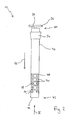
- FIGS. 1 to 9 Exemplary embodiments of the device according to the invention are in the FIGS. 1 to 9 are shown and explained with reference to this and denoted in their entirety by the reference numerals 10, 12, 14, 16 and 18. In this case, identical features among the respective embodiments are each denoted by the identical reference numerals.
- the device 10 in FIG Fig. 1 includes a rod-shaped housing 20 having a first end 22 and a second end 24, opposite from the first end 22, on.
- the device 10 further comprises an internal cavity in the housing 20, in which an ozone generating unit is arranged.
- This ozone generating unit is not closer in here Fig. 1 and in the context of the device 10, but in the following in connection with the embodiment of the device 12 and the Figures 2 ff. described in more detail and by way of example.
- the device 10 has a sealing element 26.
- This sealing element 26 is designed conically in the present embodiment, wherein it is in the direction of the second end 24th becomes narrower towards the first end 22.
- the sealing member 26 may preferably be made of an elastic material.
- This elastic material is preferably a rubbery material selected to be non-susceptible or only slightly susceptible to ozone.
- Non-limiting examples of such rubbery substances are, for example, synthetic rubbers such as ethylene-propylene-diene rubber (EPDM), and more preferably silicones or silicone rubbers.
- EPDM ethylene-propylene-diene rubber
- non-elastic sealing elements may be used, which are also preferably made of ozone-resistant substances. Examples of this may be sealing elements made of stainless steel or preferably polytetrafluoroethylene (Teflon®).
- a multiplicity of openings 28 are arranged in the housing 20 of the device 10. These openings 28 are configured here as round holes 30. The openings 28 and circular holes 30 extend up to the first end 22. Although due to the nature of the representation in the Fig. 1 Only one side of the device 10 is shown, the openings 28 are circumferentially on the housing 20, that is also on the rear side of the device 10, not shown, arranged.
- the housing 20 of the device 10 is otherwise formed as a tubular rod, that has a round cross-section. At the first end 22 of this tube, so the housing 20, closed with a lid 32.
- This cover 32 may be either a completely closed lid made of continuous material, or else openings which, for example, are comparable to the round holes 30.
- the housing has a handle 34.
- This handle 34 serves on the one hand for holding the device 10 by hand when inserting or removing the device 10 according to the invention in a container to be disinfected.
- the handle 34 also has a power connection 36 via which the electrical power supply of the ozone generating unit arranged in the housing 20 can be ensured.
- a current-carrying cable is plugged into this power connector 36.
- the power connector 36 has this common connection devices, such as sockets, on.
- the second embodiment of the device 12 in Fig. 2 also has a housing 40.
- This housing 40 also has a first end 42 and a second end 44.
- the housing 40 of the device 12 is rod-shaped and has a round cross-section, as shown in particular in the illustration of Fig. 3 you can see. Fig. 3
- the side of the device 12 at the first end 42 of the housing 40 which is closed by a cover 46.
- the device like the device 10, has a handle 34 with a power connection 36. Furthermore, a sealing element 26 is located in the area of the second end 44.
- the device 12 has openings 48, which are arranged only in the region of the first end 42 in the housing 40.
- an arrangement in the region of the first end 42 means that in view of the entire length of the housing 40, the corresponding openings occur only after half, preferably in the last third, the distance between the second end 44 and first end 42 and thus in the direction of the first end 42 are present in the housing 40.
- the openings 48 in the device 12 are designed here as longitudinal slots 50.
- the longitudinal slots 50 are configured in the device 12 so that they extend transversely to the longitudinal extent of the housing 40, which is indicated by an arrow 52.
- the longitudinal slots 50 shown here extend circumferentially around the housing 40 and are therefore also arranged in a comparable manner on the rear side of the device 12 (not shown here).
- the term "back” here refers to the side facing away from the viewer of the representation of Fig. 2 , This also applies to the previously made statements in connection with the device 10 in Fig. 1 ,
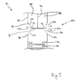
- a section through the device 12 in the region of the first end 42 is shown.
- the device 12, or the housing 40 has an inner cavity 54.
- an ozone generating unit 56 is also arranged in the region of the first end 42.
- the ozone generating unit 56 is disposed at the end of the collection of the openings 48, which faces the second end 44. With reference to the representation of Figures 2 and 4 Thus, the ozone generating unit 56 is located above the openings 48.
- the ozone generating unit 56 has two ceramic halves 58 and 60 in this embodiment. Between these ceramic halves 58 and 60, an induction electrode 62 is arranged. On the opposite side of the ceramic half 60 and in the example shown here to the openings 50 toward a discharge electrode 64 is disposed on the ceramic half 60. Thus, the induction electrode 62 and the discharge electrode 64 by a dielectric, in this embodiment, the ceramic half 60, separated from each other. For the purpose of isolation, the outer discharge electrode 64 may be covered by another layer, which is not shown in detail here.
- ozone-containing air 72 is then due to the aforementioned convection from the inner cavity 54 of the housing 40 again transported to the outside. This is indicated by arrows 74.
- the further mode of action of the ozone-containing air 72 will be discussed later in connection with FIGS. 8 and 9 explained in more detail.
- the lid 46 may be replaced by a fan.
- the fan is thus arranged at the first end 42 of the housing 40.
- the embodiment of the device 14, shown in FIG Fig. 5 shows essentially a comparable structure to the devices 10 and 12 and in particular has the openings 48 shown in the device 12 in the form of the longitudinal slots 50 in the region of the first end 42. These openings 48 are arranged in a housing 78 of the device 14. The remaining regions of the second end 44 with the handle 34 and the sealing element 26, which are not shown here in greater detail, are designed essentially identical to the devices 10 and 12.
- the housing 78 has with reference to the illustration of Fig. 5 above the openings 48, that is, facing the second end 44, openings 80 and 82 on. These openings 80 and 82 are shown here in a sectional view and otherwise have a circular shape. In each case, an edge 84 or 86 forms at the respective openings 80 and 82.
- the housing 78 of the device 14 also has an inner cavity 88.
- a pointed electrode 90 is arranged in this inner cavity 88.
- This pointed electrode is characterized by tapered ends, each having peaks 92 and 94. These tips 92, 94 are preferably aligned so that they each have a uniform distance from the circular edge 84 and 86, respectively, and thus point substantially to the center of the respective opening 80 and 82, respectively.
- the pointed electrode 90 is connected via a feed line 96 to a power source. Further, another lead 98 also connects the housing 78 to the power source.
- the housing 78 thus also forms an electrode 99.
- the two leads 96 and 98 are also preferably guided through the inner cavity 88 of the device 14, and the housing 78 to the second end 44, where they preferably end at the power connector 36 in the handle 34 and can be connected to a power source.
- two electrodes are present, one is formed by the pointed electrode 90, while the other electrode 99 is formed by the housing 78 of the device 14.
- the electrons, and possibly already formed ions and radicals are accelerated in the direction of the openings 80 and 82, or towards their edges 84 and 86, whereupon these also partly outside the inner cavity 88 of the device 14 arrive.
- Oxygen-containing air 68 (not shown here) can penetrate through the longitudinal slots 50, ie the openings 48, into the inner cavity 88, is conveyed to the pointed electrode 90 and there again out of the inner cavity due to the electron sprays 100, 102 through the openings 80 and 82 88 and thus transported out of the housing 78 to the outside.
- ozone-containing air 72 is formed and transported into the interior of a respective container for disinfection. Due to the formation of ozone, and other reactive species, such as O or OH radicals, by the respective electron spray 100 and 102 instead of directly on an electrode surface is no formation of deposits by any existing organic molecules in the oxygen-containing air 68 at the pointed-shaped electrode 90 instead. This arrangement is therefore very low maintenance.
- Both the ozone generating unit 104 and the ozone generating unit 56 may generate ozone in dry air and especially in humid air. This is on the one hand especially in the disinfection of residual moisture contained containers, such as wooden barrels, advantage and opens to another the ability to simultaneously deliver hydrogen peroxide. This latter possibility will be explained in more detail below.
- the embodiment of the device 16 shown in FIG Fig. 6 also has a total structure comparable to the devices 10 and 12.
- the part of the second end, not shown, may be considered substantially identical to the devices 10 and 12.
- the device 16 has a housing 106 which has an internal cavity 108.
- a UV light source 112 is provided in addition to an ozone generating unit 110 shown only schematically here.
- the embodiment of the ozone generating unit 110 may be selected as needed and is preferably one of the aforementioned ozone generating units 56 or 104.
- the housing 106 has a first end 114 closed by a lid 116. Both the ozone generating unit 110 and the UV light source 112 generate heat, which again results in convection of air.
- FIG Fig. 6 This air convection within the housing 106 is here in FIG Fig. 6 indicated by an arrow 118.
- the housing 106 of the device 16 also has a plurality of openings 120 in the region of the first end 114. These openings are here in the illustration of Fig. 6 indicated only schematically. In this case, both an arrangement of round holes 30, which can be compared to the device 10, and longitudinal slots 50 corresponding to the device 12 in the device 16 can be provided.
- oxygen-containing air 68 flows through these openings 120 into the inner cavity 108 of the housing 106. This is indicated schematically by arrows 122.
- the oxygen-containing air 68 is then converted to ozone-containing air 72 at the ozone generating unit 110. This flows then, as indicated by arrows 124, through further openings 120 again from the inner cavity 108 of the housing 106 to the outside.
- further ozone-containing air 72 flows within the inner cavity 108 in accordance with the convection 118 in the direction of the UV light source 112. This is indicated by a further arrow 126.
- This ozone-containing air 72 in the inner cavity 108 can now lead to the formation of hydrogen peroxide in the presence of atmospheric moisture, that is in the presence of water or water vapor, and under the action of the UV radiation of the UV light source 112. This then resulting hydrogen peroxide-containing air 128 can then pass through openings 120 also to the outside. This is indicated by a further arrow 130.
- hydrogen peroxide is also very well suited as a disinfectant, it is provided in a preferred embodiment that the formation of hydrogen peroxide is favored.
- water preferably distilled water 132
- water vapor formed above this distilled water 132 moves in the direction of the ozone generating unit 110 and the UV light source 112. This is additionally indicated by arrows 134.
- a separate heat source or other vapor generating element may be provided to specifically evaporate the distilled water 132.
- UV light rays 136 In addition to the formation of hydrogen peroxide within the inner cavity 108 of the housing 106, this is also outside of the housing 106.
- UV light rays 136 As indicated by the corresponding arrows, through the openings 120 to the outside.
- no openings 120 are provided at the level of the UV light source 112 in the illustrated embodiment of the device 16, so that first a reflection of the UV light rays 136 takes place on the inner wall of the housing 106 and thus a gain of the UV Lichtstahlen 136 occurs. Exited from the housing 106, these UV light rays 136 can then also ensure that outside of the housing 106 existing ozone reacts with water to hydrogen peroxide.
- the UV light radiation in the form of the light rays 136 promotes the formation of chain reactions which can be induced and maintained by UV light and thus also the degradation of organic compounds present within a container to be disinfected. This will thus further contribute to the disinfection and elimination of unwanted and harmful odors and flavors.
- the embodiment of the device 18 in Fig. 7 again has a similar construction to the devices 10 and 12 of the present invention. This means that in particular the region of the second end (not shown here) with the handle and the sealing element is identical to these devices.
- the device 18 further includes a housing 140 having a first end 142 and an interior cavity 144.
- the inner cavity 144 is closed at the first end 142 by means of a cover 146.
- the housing 140 also has openings 148 which, as in the case of the device 16, can be configured as round holes 30 or elongated slots 52, comparable to the embodiments of the devices 10 and 12.
- an ozone generating unit 110 is provided which, as in the case of the device 16, can be configured from the devices 12 and 14 in accordance with one of the above-described embodiments for ozone generating units 56 or 104.
- a convection 118 likewise arises again, as has already been explained in connection with the device 16.
- oxygen-containing air 68 flows into the openings 148 of the housing 140 in accordance with the arrows 122.
- ozone-containing air 72 is then generated at the ozone generating unit 110 and led back out of the housing 140 due to the convection according to the arrows 124 through the openings 148 to the outside.
- the device 18 has a UV light source 150 at the first end 142.
- This UV light source is protected in the present embodiment by a UV-transparent cap 152 protective.
- UV light in the form of UV light rays 154 is radiated outwards into the interior of a corresponding container to be disinfected. Due to existing moisture in the air and generally in the interior of the container to be disinfected, it can now come by the supply of ozone-containing air 72 again to the formation of hydrogen peroxide under the action of the UV light rays 154. Furthermore, there is also the possibility here that 154 chain reactions can be started and / or maintained in the interior of the respective container by the UV light rays 154.
- the UV light sources 112 and 150 of the devices 16 and 18 can also be used to provide after switching off the respective ozone generating unit 110 for accelerated degradation, that is for a faster decomposition of the residual ozone in the interior of the container , This is also transferable to the devices 10, 12 and 14 when modified with UV light sources.
- a wooden container in the form of a wooden barrel 160 is shown.
- This wooden barrel 160 has at its upper end, ie on the lid an opening 162.
- This opening 162 is usually designed as a round opening.
- the device 12 of the invention is inserted through the opening 162.
- the opening 162 receives the device 12 on the sealing element 26.
- the second end 44 comes with the handle 34 and the terminal 36 outside the container, so the wooden barrel 160 to lie.
- the remaining part with the first end 42 and the openings 48 and the ozone generating unit 56 which is arranged in the inner cavity 54 of the housing 40, in the interior 164 of the wooden barrel 160. Since the wooden barrel 160 has no other openings or these preferably closed are, the interior 164 and thus the wooden barrel 160 is closed.
- 160 oxygen-containing air 68 is found in the interior 164 of the barrel.
- a cable 166 is arranged, which in turn is connected to a power source 167 and is conducted via the current along the cable 76 to the ozone generating unit 56. This supply of the current is further indicated by an arrow 168 in FIG Fig. 9 indicated.
- oxygen-containing air 68 then flows, indicated by arrows 70, into the inner cavity 54 of the housing 40.
- This oxygen-containing air 68 enters through the openings 48 into the inner cavity 54 and is guided into the discharge zone 66, as in FIG this already eg in connection with the Fig. 4 was explained.
- the thus formed ozone-containing air 72 is then, as indicated by arrows 74, again through the openings 48 from the inner Cavity 54 passed into the interior 164 of the barrel 160.
- a distribution of this ozone-containing air 72 is then achieved due to the convection and / or imparted by diffusion.
- a UV light source 112 and 150 may be provided.
- this can favor a generation of hydrogen peroxide, which can likewise lead to a disinfecting effect on the surface and generally in the interior 164 of a wooden barrel 160.
- additional (distilled) water 132 are provided so that the corresponding Water vapor 134 may already be present during ozone production.
- the effects of the resulting hydrogen peroxide-containing air 128 are then comparable to and analogous to the explanations in connection with the Fig. 9 and the ozone-containing air 72.
- Both hydrogen peroxide-containing air 128 and ozone-containing air 72 react with time without residue and thus, after switching off the ozone generation, no health hazard.
Landscapes
- Health & Medical Sciences (AREA)
- Animal Behavior & Ethology (AREA)
- Public Health (AREA)
- Veterinary Medicine (AREA)
- Epidemiology (AREA)
- Life Sciences & Earth Sciences (AREA)
- General Health & Medical Sciences (AREA)
- Chemical & Material Sciences (AREA)
- Chemical Kinetics & Catalysis (AREA)
- General Chemical & Material Sciences (AREA)
- Physics & Mathematics (AREA)
- Plasma & Fusion (AREA)
- Engineering & Computer Science (AREA)
- Apparatus For Disinfection Or Sterilisation (AREA)
- Oxygen, Ozone, And Oxides In General (AREA)
Claims (14)
- Dispositif destiné à la désinfection de la partie intérieure (164) d'un récipient (160) avec- un boîtier en forme de tige (20, 40, 78, 106, 140), avec une première extrémité (22, 42, 114, 142) pour la mise en place à l'intérieure du récipient (160), une deuxième extrémité (24, 44) située en face et un espace creux interne (54, 108, 144),
caractérisé par- une unité de génération d'ozone (56, 104, 110) dans l'espace creux interne (54, 108, 144), et- au moins une multiplicité d'orifices (28, 48, 120, 148) dans le boîtier (20, 40, 78, 106, 140) dans la partie de sa première extrémité (22, 42, 114, 142),
dans lequel le boîtier (20, 40, 78, 106, 140) présente un élément d'étanchéité (26) à l'extérieur de la deuxième extrémité (24, 44), par lequel le dispositif peut être admis de manière étanche dans un orifice (162) du récipient (160). - Dispositif selon la revendication 1, caractérisé en ce que le boîtier (20, 40, 78, 106, 140) présente une section transversale circulaire.
- Dispositif selon les revendications 1 ou 2, caractérisé en ce que le boîtier (20, 40, 78, 106, 140) est en métal.
- Dispositif selon l'une des revendications 1 à 3, caractérisé en ce que la multiplicité des orifices dans le boîtier (20, 40, 78, 106, 140) est conçue sous la forme de trous circulaires (30).
- Dispositif selon l'une des revendications 1 à 3, caractérisé en ce que la multiplicité des orifices (28, 48, 120, 148) dans le boîtier (20, 40, 78, 106, 140) est conçue sous la forme de fentes allongées (50).
- Dispositif selon l'une des revendications 1 à 5, caractérisé en ce que l'unité génératrice d'ozone (56, 110) présente une électrode d'induction (62) et une électrode de décharge (64), qui sont séparées l'une de l'autre par un diélectrique solide (60).
- Dispositif selon l'une des revendications 1 à 5, caractérisé en ce que l'unité génératrice d'ozone (104, 110) présente une première électrode en forme de pointe (90) et une deuxième électrode (99), où la deuxième électrode (99) est formée par le boîtier (20, 40, 78, 106, 140) et le boîtier (20, 40, 78, 106, 140), vu dans le sens longitudinal, présente au moins un orifice (80, 82) de la hauteur de l'électrode en forme de pointe.
- Dispositif selon l'une des revendications 1 à 7, caractérisé en ce que le dispositif présente en outre une source de lumière UV (112 ; 150) qui est disposée dans le boîtier (20, 40, 78, 106, 140) et/ou sur le boîtier (20, 40, 78, 106, 140) à l'extérieur.
- Dispositif selon l'une des revendications 1 à 8, caractérisé en ce que le boîtier (20, 40, 78, 106, 140) est constitué d'un matériau inerte, en particulier en acier inoxydable, et/ou en matière synthétique, et/ou en aluminium, et/ou en argent, et/ou en palladium, notamment au moins partiellement dans la partie de sa première extrémité (22, 42, 114, 142).
- Dispositif selon l'une des revendications 1 à 9, caractérisé en ce que le boîtier (20, 40, 78, 106, 140) présente au moins partiellement un matériau à base d'oxyde métallique, dans la partie de sa première extrémité (22,42, 114, 142), où, de préférence, le boîtier présente un revêtement à base d'oxyde métallique ou une enveloppe à base d'oxyde métallique dans la partie de sa première extrémité, notamment, un revêtement à base d'oxyde avec de l'oxyde d'aluminium, et/ou d'oxyde de cuivre, et/ou d'oxyde de manganèse.
- Procédé destiné à la désinfection de la partie intérieure (164) de récipients en bois (160) par la fourniture d'ozone dans le récipient en bois (160), où l'ozone est généré dans le récipient en bois (160) et où le procédé présente les étapes suivantes :- mise en place d'une unité de génération d'ozone (56, 104, 110) selon la revendication 1 dans le récipient en bois (160),- fermeture du récipient en bois (160)- génération d'ozone par l'unité de génération d'ozone (58, 104, 110).
- Procédé selon la revendication 11, caractérisé en ce que la génération d'ozone est effectuée de manière continue.
- Procédé selon la revendication 11 ou la revendication 12, caractérisé en ce que la partie intérieure (164) du récipient en bois (160) est en outre soumise à une lumière UV.
- Procédé selon la revendication 13, caractérisé en ce qu'en outre de la vapeur d'eau (134) est préparée dans la partie intérieure (164).
Applications Claiming Priority (1)
| Application Number | Priority Date | Filing Date | Title |
|---|---|---|---|
| DE102012108042.9A DE102012108042A1 (de) | 2012-08-30 | 2012-08-30 | Vorrichtung und Verfahren zur Desinfektion von Behältern |
Publications (2)
| Publication Number | Publication Date |
|---|---|
| EP2703012A1 EP2703012A1 (fr) | 2014-03-05 |
| EP2703012B1 true EP2703012B1 (fr) | 2015-07-15 |
Family
ID=48948194
Family Applications (1)
| Application Number | Title | Priority Date | Filing Date |
|---|---|---|---|
| EP13003888.8A Active EP2703012B1 (fr) | 2012-08-30 | 2013-08-05 | Dispositif et procédé destinés à la désinfection de récipients |
Country Status (3)
| Country | Link |
|---|---|
| US (1) | US9452231B2 (fr) |
| EP (1) | EP2703012B1 (fr) |
| DE (1) | DE102012108042A1 (fr) |
Families Citing this family (13)
| Publication number | Priority date | Publication date | Assignee | Title |
|---|---|---|---|---|
| KR20240133776A (ko) | 2017-03-27 | 2024-09-04 | 리제너론 파아마슈티컬스, 인크. | 살균 방법 |
| US11767242B2 (en) * | 2017-12-29 | 2023-09-26 | Surfplasma, Inc. | Compact portable plasma reactor |
| JP2019187675A (ja) * | 2018-04-23 | 2019-10-31 | 孝司 南 | タンク内殺菌装置及びその方法 |
| CN109677182A (zh) * | 2018-12-25 | 2019-04-26 | 赤水市牵手竹艺发展有限公司 | 一种竹编工艺品的防虫处理方法 |
| MA54325A (fr) | 2019-06-05 | 2022-05-11 | Regeneron Pharma | Dispositifs et procédés pour l'administration précise de doses |
| JP1668331S (fr) * | 2019-09-09 | 2020-09-14 | ||
| JP1668366S (fr) * | 2020-02-06 | 2020-09-14 | ||
| EP4173648B1 (fr) * | 2020-06-30 | 2025-11-05 | Canon Kabushiki Kaisha | Dispositif et procédé de stérilisation, dispositif d'alimentation en oxygène actif et dispositif de traitement par de l'oxygène actif |
| FR3117047B1 (fr) * | 2020-12-08 | 2022-12-23 | Tonnellerie De Lentre Deux Mers T E D E M | Procédé de nettoyage d’un fût en bois |
| JP7844162B2 (ja) * | 2021-12-28 | 2026-04-13 | キヤノン株式会社 | 活性酸素による処理装置及び活性酸素による処理方法 |
| JP7844163B2 (ja) * | 2021-12-28 | 2026-04-13 | キヤノン株式会社 | 活性酸素による処理装置及び活性酸素による処理方法 |
| USD1120314S1 (en) | 2022-11-30 | 2026-03-24 | Regeneron Pharmaceuticals, Inc. | Dose delivery device |
| CN116474150B (zh) * | 2023-06-08 | 2025-10-31 | 中国人民解放军总医院第六医学中心 | 一种高压氧舱用消毒装置 |
Family Cites Families (13)
| Publication number | Priority date | Publication date | Assignee | Title |
|---|---|---|---|---|
| US3383163A (en) * | 1964-01-24 | 1968-05-14 | Little Inc A | Treatment of surfaces |
| DE3502242A1 (de) * | 1985-01-24 | 1986-07-24 | Silberzahn, Helmut, 6950 Mosbach | Verfahren zum reinigen und sterilisieren von faessern |
| DE19542447C2 (de) * | 1995-11-14 | 1998-09-17 | Herbert K Malek | Vorrichtung zum Dampfsterilisieren eines gespülten Behälters, insbesondere eines KEG-Fasses für Bier |
| US5733512A (en) * | 1997-04-18 | 1998-03-31 | Industrial Technology Research Institute | Ozone generating device |
| US5928607A (en) * | 1997-08-15 | 1999-07-27 | Tetra Laval Holdings & Finance, Sa | Bottle sterilization method and apparatus |
| TW467770B (en) * | 2000-10-24 | 2001-12-11 | Huei-Tang Liou | Gold plating method for quartz or high alumina tube of high heat resistance and high voltage resistance, and gold-plated quartz and high alumina tube for the application of ozone generator |
| AUPR861401A0 (en) * | 2001-11-02 | 2001-11-29 | Ozone Manufacturing Pty Ltd | Ice machine purifier |
| TW559616B (en) * | 2003-01-22 | 2003-11-01 | Senno Technology Inc | Ultraviolet-and-ozone disinfection apparatus having improvement on disinfection effect |
| US8353906B2 (en) * | 2005-08-01 | 2013-01-15 | Ceramatec, Inc. | Electrochemical probe and method for in situ treatment of a tissue |
| CA2547183A1 (fr) * | 2006-05-17 | 2007-11-17 | Ozomax Inc. | Ozoneur portable pour l'epuration des eaux et utilisation connexe |
| WO2012166203A1 (fr) * | 2011-06-01 | 2012-12-06 | Alexander Farren | Stérilisation de récipients aux ultraviolets |
| US10081864B2 (en) * | 2011-03-10 | 2018-09-25 | Kaiatech, Inc | Method and apparatus for treating containers |
| DE102011016448A1 (de) | 2011-03-29 | 2012-10-04 | Khs Corpoplast Gmbh | Verfahren zum Sterilisieren sowie Vorrichtung zur Blasformung von Behältern |
-
2012
- 2012-08-30 DE DE102012108042.9A patent/DE102012108042A1/de not_active Withdrawn
-
2013
- 2013-08-05 EP EP13003888.8A patent/EP2703012B1/fr active Active
- 2013-08-23 US US13/974,222 patent/US9452231B2/en not_active Expired - Fee Related
Also Published As
| Publication number | Publication date |
|---|---|
| DE102012108042A1 (de) | 2014-03-06 |
| EP2703012A1 (fr) | 2014-03-05 |
| US9452231B2 (en) | 2016-09-27 |
| US20140065013A1 (en) | 2014-03-06 |
Similar Documents
| Publication | Publication Date | Title |
|---|---|---|
| EP2703012A1 (fr) | Dispositif et procédé destinés à la désinfection de récipients | |
| DE102004049783B4 (de) | Vorrichtung zur Bearbeitung von Gütern unter Zuhilfenahme einer elektrischen Entladung | |
| DE4340788C2 (de) | Vorrichtung und Verfahren zum Verhindern der Ausbreitung von Mikroben | |
| DE60010784T2 (de) | Verfahren zur verstärkten Sterilisation mit verbesserter Materialkompatibilität | |
| EP2566524B1 (fr) | Procédé de stérilisation par un gaz généré par un plasma | |
| CH648155A5 (de) | Quecksilber-niederdrucklampe. | |
| DE102008037898B4 (de) | Verfahren und Vorrichtung zur Sterilisation von Verpackungsmaterial und/oder Behältern, diesbezügliche Verwendung von Plasma sowie entsprechend behandeltes Material oder Behälter | |
| DE3603900A1 (de) | Trinkwasserreinigungseinrichtung | |
| WO2011116984A2 (fr) | Procédé et dispositif de réduction du nombre de germes dans un volume fermé | |
| DE102007003334A1 (de) | Verfahren und Vorrichtung zur kontinuierlichen Sterilisierung von Beutelverpackungen | |
| EP2656762A2 (fr) | Séchoir, notamment séchoir à mains | |
| EP2165978A1 (fr) | Installation et procédé de préparation chimique et physique d'eau à l'aide d'un rayonnement UV | |
| WO2010006676A1 (fr) | Pansement rapide | |
| DE60010693T2 (de) | Verfahren und vorrichtung zur plasmasterilisation bei niedriger temperatur | |
| DE4440813A1 (de) | Verfahren zur Behandlung von Flüssigkeiten | |
| EP1049492B1 (fr) | Procédé de fabrication de bouchons en liège décontaminés et stérilisés | |
| EP3481438A1 (fr) | Dispositif de désinfection et procédé de désinfection | |
| DE19507189C2 (de) | Verfahren zur Mediumaufbereitung mit einem Excimer-Strahler und Excimer-Strahler zur Durchführung eines solchen Verfahrens | |
| DE102009016542A1 (de) | Verfahren zur Desinfektion von Oberflächen flowdurchströmter Bereiche durch Nutzung synergistischer Wirkungen desinfektionswirksamer Mittel | |
| DE10040566A1 (de) | Verfahren und Vorrichtung zur Aufbereitung eines aquatischen Systems | |
| EP0818206B1 (fr) | Procédé et dispositif pour nettoyer et désinfecter de petits objets et dispositif | |
| DE19615735A1 (de) | Vorrichtung zum Sterilisieren der Innenflächen von druckempfindlichen Behältern | |
| WO2022195029A1 (fr) | Procédé et dispositif permettant la désinfection, en particulier la stérilisation, de produits emballés | |
| DE102017123871A1 (de) | Verfahren zur Oberflächendesinfektion und zur Desinfektion von Komponenten einer Abfüllanlage | |
| WO1996027302A1 (fr) | Procede et dispositif de traitement de denrees alimentaires |
Legal Events
| Date | Code | Title | Description |
|---|---|---|---|
| AK | Designated contracting states |
Kind code of ref document: A1 Designated state(s): AL AT BE BG CH CY CZ DE DK EE ES FI FR GB GR HR HU IE IS IT LI LT LU LV MC MK MT NL NO PL PT RO RS SE SI SK SM TR |
|
| AX | Request for extension of the european patent |
Extension state: BA ME |
|
| PUAI | Public reference made under article 153(3) epc to a published international application that has entered the european phase |
Free format text: ORIGINAL CODE: 0009012 |
|
| RIN1 | Information on inventor provided before grant (corrected) |
Inventor name: NONNENMACHER, KLAUS, PROF.DIPL.-ING. |
|
| 17P | Request for examination filed |
Effective date: 20140814 |
|
| RBV | Designated contracting states (corrected) |
Designated state(s): AL AT BE BG CH CY CZ DE DK EE ES FI FR GB GR HR HU IE IS IT LI LT LU LV MC MK MT NL NO PL PT RO RS SE SI SK SM TR |
|
| GRAP | Despatch of communication of intention to grant a patent |
Free format text: ORIGINAL CODE: EPIDOSNIGR1 |
|
| INTG | Intention to grant announced |
Effective date: 20150217 |
|
| GRAS | Grant fee paid |
Free format text: ORIGINAL CODE: EPIDOSNIGR3 |
|
| GRAA | (expected) grant |
Free format text: ORIGINAL CODE: 0009210 |
|
| AK | Designated contracting states |
Kind code of ref document: B1 Designated state(s): AL AT BE BG CH CY CZ DE DK EE ES FI FR GB GR HR HU IE IS IT LI LT LU LV MC MK MT NL NO PL PT RO RS SE SI SK SM TR |
|
| REG | Reference to a national code |
Ref country code: CH Ref legal event code: EP Ref country code: GB Ref legal event code: FG4D Free format text: NOT ENGLISH |
|
| REG | Reference to a national code |
Ref country code: IE Ref legal event code: FG4D Free format text: LANGUAGE OF EP DOCUMENT: GERMAN |
|
| REG | Reference to a national code |
Ref country code: AT Ref legal event code: REF Ref document number: 736441 Country of ref document: AT Kind code of ref document: T Effective date: 20150815 |
|
| REG | Reference to a national code |
Ref country code: DE Ref legal event code: R096 Ref document number: 502013000866 Country of ref document: DE |
|
| REG | Reference to a national code |
Ref country code: NL Ref legal event code: MP Effective date: 20150715 |
|
| REG | Reference to a national code |
Ref country code: LT Ref legal event code: MG4D |
|
| PG25 | Lapsed in a contracting state [announced via postgrant information from national office to epo] |
Ref country code: NO Free format text: LAPSE BECAUSE OF FAILURE TO SUBMIT A TRANSLATION OF THE DESCRIPTION OR TO PAY THE FEE WITHIN THE PRESCRIBED TIME-LIMIT Effective date: 20151015 Ref country code: LV Free format text: LAPSE BECAUSE OF FAILURE TO SUBMIT A TRANSLATION OF THE DESCRIPTION OR TO PAY THE FEE WITHIN THE PRESCRIBED TIME-LIMIT Effective date: 20150715 Ref country code: LT Free format text: LAPSE BECAUSE OF FAILURE TO SUBMIT A TRANSLATION OF THE DESCRIPTION OR TO PAY THE FEE WITHIN THE PRESCRIBED TIME-LIMIT Effective date: 20150715 Ref country code: GR Free format text: LAPSE BECAUSE OF FAILURE TO SUBMIT A TRANSLATION OF THE DESCRIPTION OR TO PAY THE FEE WITHIN THE PRESCRIBED TIME-LIMIT Effective date: 20151016 Ref country code: FI Free format text: LAPSE BECAUSE OF FAILURE TO SUBMIT A TRANSLATION OF THE DESCRIPTION OR TO PAY THE FEE WITHIN THE PRESCRIBED TIME-LIMIT Effective date: 20150715 |
|
| PG25 | Lapsed in a contracting state [announced via postgrant information from national office to epo] |
Ref country code: SE Free format text: LAPSE BECAUSE OF FAILURE TO SUBMIT A TRANSLATION OF THE DESCRIPTION OR TO PAY THE FEE WITHIN THE PRESCRIBED TIME-LIMIT Effective date: 20150715 Ref country code: HR Free format text: LAPSE BECAUSE OF FAILURE TO SUBMIT A TRANSLATION OF THE DESCRIPTION OR TO PAY THE FEE WITHIN THE PRESCRIBED TIME-LIMIT Effective date: 20150715 Ref country code: PL Free format text: LAPSE BECAUSE OF FAILURE TO SUBMIT A TRANSLATION OF THE DESCRIPTION OR TO PAY THE FEE WITHIN THE PRESCRIBED TIME-LIMIT Effective date: 20150715 Ref country code: RS Free format text: LAPSE BECAUSE OF FAILURE TO SUBMIT A TRANSLATION OF THE DESCRIPTION OR TO PAY THE FEE WITHIN THE PRESCRIBED TIME-LIMIT Effective date: 20150715 Ref country code: PT Free format text: LAPSE BECAUSE OF FAILURE TO SUBMIT A TRANSLATION OF THE DESCRIPTION OR TO PAY THE FEE WITHIN THE PRESCRIBED TIME-LIMIT Effective date: 20151116 Ref country code: ES Free format text: LAPSE BECAUSE OF FAILURE TO SUBMIT A TRANSLATION OF THE DESCRIPTION OR TO PAY THE FEE WITHIN THE PRESCRIBED TIME-LIMIT Effective date: 20150715 |
|
| REG | Reference to a national code |
Ref country code: DE Ref legal event code: R097 Ref document number: 502013000866 Country of ref document: DE |
|
| PG25 | Lapsed in a contracting state [announced via postgrant information from national office to epo] |
Ref country code: SK Free format text: LAPSE BECAUSE OF FAILURE TO SUBMIT A TRANSLATION OF THE DESCRIPTION OR TO PAY THE FEE WITHIN THE PRESCRIBED TIME-LIMIT Effective date: 20150715 Ref country code: DK Free format text: LAPSE BECAUSE OF FAILURE TO SUBMIT A TRANSLATION OF THE DESCRIPTION OR TO PAY THE FEE WITHIN THE PRESCRIBED TIME-LIMIT Effective date: 20150715 Ref country code: MC Free format text: LAPSE BECAUSE OF FAILURE TO SUBMIT A TRANSLATION OF THE DESCRIPTION OR TO PAY THE FEE WITHIN THE PRESCRIBED TIME-LIMIT Effective date: 20150715 Ref country code: EE Free format text: LAPSE BECAUSE OF FAILURE TO SUBMIT A TRANSLATION OF THE DESCRIPTION OR TO PAY THE FEE WITHIN THE PRESCRIBED TIME-LIMIT Effective date: 20150715 Ref country code: CZ Free format text: LAPSE BECAUSE OF FAILURE TO SUBMIT A TRANSLATION OF THE DESCRIPTION OR TO PAY THE FEE WITHIN THE PRESCRIBED TIME-LIMIT Effective date: 20150715 |
|
| PLBE | No opposition filed within time limit |
Free format text: ORIGINAL CODE: 0009261 |
|
| STAA | Information on the status of an ep patent application or granted ep patent |
Free format text: STATUS: NO OPPOSITION FILED WITHIN TIME LIMIT |
|
| PG25 | Lapsed in a contracting state [announced via postgrant information from national office to epo] |
Ref country code: RO Free format text: LAPSE BECAUSE OF FAILURE TO SUBMIT A TRANSLATION OF THE DESCRIPTION OR TO PAY THE FEE WITHIN THE PRESCRIBED TIME-LIMIT Effective date: 20150715 |
|
| REG | Reference to a national code |
Ref country code: IE Ref legal event code: MM4A |
|
| 26N | No opposition filed |
Effective date: 20160418 |
|
| REG | Reference to a national code |
Ref country code: FR Ref legal event code: PLFP Year of fee payment: 4 |
|
| PG25 | Lapsed in a contracting state [announced via postgrant information from national office to epo] |
Ref country code: IS Free format text: LAPSE BECAUSE OF FAILURE TO SUBMIT A TRANSLATION OF THE DESCRIPTION OR TO PAY THE FEE WITHIN THE PRESCRIBED TIME-LIMIT Effective date: 20150715 |
|
| PG25 | Lapsed in a contracting state [announced via postgrant information from national office to epo] |
Ref country code: IE Free format text: LAPSE BECAUSE OF NON-PAYMENT OF DUE FEES Effective date: 20150805 |
|
| PG25 | Lapsed in a contracting state [announced via postgrant information from national office to epo] |
Ref country code: SI Free format text: LAPSE BECAUSE OF FAILURE TO SUBMIT A TRANSLATION OF THE DESCRIPTION OR TO PAY THE FEE WITHIN THE PRESCRIBED TIME-LIMIT Effective date: 20150715 |
|
| PG25 | Lapsed in a contracting state [announced via postgrant information from national office to epo] |
Ref country code: MT Free format text: LAPSE BECAUSE OF FAILURE TO SUBMIT A TRANSLATION OF THE DESCRIPTION OR TO PAY THE FEE WITHIN THE PRESCRIBED TIME-LIMIT Effective date: 20150715 |
|
| PG25 | Lapsed in a contracting state [announced via postgrant information from national office to epo] |
Ref country code: HU Free format text: LAPSE BECAUSE OF FAILURE TO SUBMIT A TRANSLATION OF THE DESCRIPTION OR TO PAY THE FEE WITHIN THE PRESCRIBED TIME-LIMIT; INVALID AB INITIO Effective date: 20130805 Ref country code: BG Free format text: LAPSE BECAUSE OF FAILURE TO SUBMIT A TRANSLATION OF THE DESCRIPTION OR TO PAY THE FEE WITHIN THE PRESCRIBED TIME-LIMIT Effective date: 20150715 |
|
| PG25 | Lapsed in a contracting state [announced via postgrant information from national office to epo] |
Ref country code: NL Free format text: LAPSE BECAUSE OF FAILURE TO SUBMIT A TRANSLATION OF THE DESCRIPTION OR TO PAY THE FEE WITHIN THE PRESCRIBED TIME-LIMIT Effective date: 20150715 Ref country code: CY Free format text: LAPSE BECAUSE OF FAILURE TO SUBMIT A TRANSLATION OF THE DESCRIPTION OR TO PAY THE FEE WITHIN THE PRESCRIBED TIME-LIMIT Effective date: 20150715 |
|
| REG | Reference to a national code |
Ref country code: DE Ref legal event code: R082 Ref document number: 502013000866 Country of ref document: DE Representative=s name: OSTERTAG & PARTNER, PATENTANWAELTE MBB, DE Ref country code: DE Ref legal event code: R082 Ref document number: 502013000866 Country of ref document: DE Representative=s name: PATENTANWALTSKANZLEI CARTAGENA PARTNERSCHAFTSG, DE |
|
| PG25 | Lapsed in a contracting state [announced via postgrant information from national office to epo] |
Ref country code: BE Free format text: LAPSE BECAUSE OF NON-PAYMENT OF DUE FEES Effective date: 20150831 |
|
| REG | Reference to a national code |
Ref country code: FR Ref legal event code: PLFP Year of fee payment: 5 |
|
| PG25 | Lapsed in a contracting state [announced via postgrant information from national office to epo] |
Ref country code: LU Free format text: LAPSE BECAUSE OF NON-PAYMENT OF DUE FEES Effective date: 20150805 |
|
| GBPC | Gb: european patent ceased through non-payment of renewal fee |
Effective date: 20170805 |
|
| PG25 | Lapsed in a contracting state [announced via postgrant information from national office to epo] |
Ref country code: SM Free format text: LAPSE BECAUSE OF FAILURE TO SUBMIT A TRANSLATION OF THE DESCRIPTION OR TO PAY THE FEE WITHIN THE PRESCRIBED TIME-LIMIT Effective date: 20150715 |
|
| PG25 | Lapsed in a contracting state [announced via postgrant information from national office to epo] |
Ref country code: TR Free format text: LAPSE BECAUSE OF FAILURE TO SUBMIT A TRANSLATION OF THE DESCRIPTION OR TO PAY THE FEE WITHIN THE PRESCRIBED TIME-LIMIT Effective date: 20150715 Ref country code: MK Free format text: LAPSE BECAUSE OF FAILURE TO SUBMIT A TRANSLATION OF THE DESCRIPTION OR TO PAY THE FEE WITHIN THE PRESCRIBED TIME-LIMIT Effective date: 20150715 |
|
| PG25 | Lapsed in a contracting state [announced via postgrant information from national office to epo] |
Ref country code: GB Free format text: LAPSE BECAUSE OF NON-PAYMENT OF DUE FEES Effective date: 20170805 |
|
| REG | Reference to a national code |
Ref country code: FR Ref legal event code: PLFP Year of fee payment: 6 |
|
| PG25 | Lapsed in a contracting state [announced via postgrant information from national office to epo] |
Ref country code: AL Free format text: LAPSE BECAUSE OF FAILURE TO SUBMIT A TRANSLATION OF THE DESCRIPTION OR TO PAY THE FEE WITHIN THE PRESCRIBED TIME-LIMIT Effective date: 20150715 |
|
| REG | Reference to a national code |
Ref country code: AT Ref legal event code: MM01 Ref document number: 736441 Country of ref document: AT Kind code of ref document: T Effective date: 20180805 |
|
| PG25 | Lapsed in a contracting state [announced via postgrant information from national office to epo] |
Ref country code: AT Free format text: LAPSE BECAUSE OF NON-PAYMENT OF DUE FEES Effective date: 20180805 |
|
| REG | Reference to a national code |
Ref country code: DE Ref legal event code: R082 Ref document number: 502013000866 Country of ref document: DE Representative=s name: OSTERTAG & PARTNER, PATENTANWAELTE MBB, DE |
|
| PGFP | Annual fee paid to national office [announced via postgrant information from national office to epo] |
Ref country code: DE Payment date: 20250821 Year of fee payment: 13 |
|
| PGFP | Annual fee paid to national office [announced via postgrant information from national office to epo] |
Ref country code: IT Payment date: 20250829 Year of fee payment: 13 |
|
| PGFP | Annual fee paid to national office [announced via postgrant information from national office to epo] |
Ref country code: FR Payment date: 20250827 Year of fee payment: 13 |
|
| PGFP | Annual fee paid to national office [announced via postgrant information from national office to epo] |
Ref country code: CH Payment date: 20250901 Year of fee payment: 13 |