EP2656762A2 - Séchoir, notamment séchoir à mains - Google Patents
Séchoir, notamment séchoir à mains Download PDFInfo
- Publication number
- EP2656762A2 EP2656762A2 EP13001815.3A EP13001815A EP2656762A2 EP 2656762 A2 EP2656762 A2 EP 2656762A2 EP 13001815 A EP13001815 A EP 13001815A EP 2656762 A2 EP2656762 A2 EP 2656762A2
- Authority
- EP
- European Patent Office
- Prior art keywords
- cavity
- air flow
- dryer according
- dryer
- housing
- Prior art date
- Legal status (The legal status is an assumption and is not a legal conclusion. Google has not performed a legal analysis and makes no representation as to the accuracy of the status listed.)
- Withdrawn
Links
Images

Classifications
-
- A—HUMAN NECESSITIES
- A47—FURNITURE; DOMESTIC ARTICLES OR APPLIANCES; COFFEE MILLS; SPICE MILLS; SUCTION CLEANERS IN GENERAL
- A47K—SANITARY EQUIPMENT; ACCESSORIES THEREFOR, e.g. TOILET ACCESSORIES
- A47K10/00—Body-drying implements; Toilet paper; Holders therefor
- A47K10/48—Drying by means of hot air
-
- F—MECHANICAL ENGINEERING; LIGHTING; HEATING; WEAPONS; BLASTING
- F26—DRYING
- F26B—DRYING SOLID MATERIALS OR OBJECTS BY REMOVING LIQUID THEREFROM
- F26B20/00—Combinations of machines or apparatus covered by two or more of groups F26B9/00 - F26B19/00
Definitions
- the invention relates to a dryer, in particular a hand dryer, in which inserted through a housing opening extremities, in particular the hands, can be dried in a cavity by means of an air flow.
- Such dryers are basically known in the art. They usually include a fan or a fan, with the air is blown through one or more nozzles on the hands inserted into the cavity and they are dried.
- a hand dryer is described in which an air flow in the form of a thin air curtain is blown from slit-shaped nozzles onto the hands at high speed. The liquid blown off by the hands is collected in a collection area.
- the air used for drying is partially recirculated within the dryer and partially enters the environment of the dryer. In this way, however, contaminants adhering to the hands and, in particular, germs such as spores or bacteria can be carried along by the air and thus be released into the ambient air.
- the object of the invention is accordingly to provide a dryer which at least reduces the number of germs in the recirculated during the drying process and / or reaching the air flow and possibly also to a disinfection and / or sterilization of the dried limbs, in particular the hands and possibly the arms, can be used.
- the invention thus relates in its widest aspect to a dryer with a housing in which a cavity accessible from outside through a housing opening is present. This cavity serves to accommodate extremities to be dried, especially the hands. There is also provided an apparatus for generating an airflow used to dry the limbs inserted into the cavity.
- the dryer according to the invention has a means by which the germs present in the air flow can be reduced. This agent ensures that germs that are carried along in particular with the air flow which has been blown onto the extremities to be dried, are killed. There is therefore no longer the risk that germs entrained by the air flow enter the surroundings of the drier or are returned to the extremities of the user by recirculating the air flow within the drier.
- germ-reducing agents can be used as agents for reducing germs in the air flow.
- Suitable agents are, for example, agents which emit a germ-reducing or germ-killing substance (referred to simply as germ-reducing substance in the following) in the air flow.
- germ-reducing substance which germ-reducing substance this is, is in principle not further limited, of course, such substances should be avoided, which could lead to damage to the health of the user of the dryer.
- the germ-reducing substance is added to the air flow expediently by dusting, spraying or blowing. Suitable delivery means such as nozzles are known in the art and do not need to be described here.
- the germ-reducing substance is supplied in liquid or gaseous form. Particularly preferred is the use of at least one alcohol or an alcoholic solution or a gas containing ozone and / or free radicals.
- a plasma or ion source preferably a microwave or high frequency source
- these sources lead in the air flow to the production of a plasma or ionized gas, which in themselves already germicidal effect.
- reactive compounds such as the already mentioned ozone or free radicals are formed in secondary steps, which also act germicidal.
- those radiation sources can be used whose radiation is germicidal in itself, or those radiation sources whose radiation leads to the formation of germicidal compounds.
- Exemplary of the first possibility can be mentioned radiation sources that emit ultraviolet radiation.
- An example of the second possibility is dielectric barrier discharge lamps, the operation of which leads to the formation of a reactive plasma.
- suitable guidance of the air flow inside the dryer and appropriate arrangement of the means for reducing germs in the air flow can be specified whether the germicidal agent acts directly on the extremities to be dried or only a sterilization of the discharged air flow from the extremities.
- the means for reducing germs so that germ-killing substances are released exclusively into the air flow discharged after drying the extremities - be it by external supply of the germicidal substance or by generation within the air flow by means of irradiation, plasma or ion source.
- the extremities of the user to be dried do not come into contact with the germ-reducing substances.
- the escape of germ-reducing substances into the environment of the dryer can be prevented or at least reduced by filtering out the substance from the air flow or decomposing it into harmless degradation products.
- a filter can also serve to catch the killed germs.
- the dryer according to the invention is also to be used for disinfection and / or sterilization of the extremities
- the germ-reducing substances are supplied to the cavity in which the drying takes place. This can be done, for example, by adding enriched air with germ-reducing substance to the cavity, for example by recirculation, or by producing the germ-reducing substances in the cavity.
- the agent for reducing germs is a radiation source whose radiation itself has a germicidal effect, for example a UV emitter, this is expediently arranged in the cavity in such a way that its radiation is emitted to the limbs inserted into the cavity. Also conceivable are combinations of the possibilities described above.
- the basic structure of the dryer according to the invention can basically correspond to the structure of conventional driers and differ from these only by the use of the means for reducing nuclei in the air flow. It is therefore also possible in principle to retrofit conventional dryers by arranging a germ-reducing agent and in this way to achieve the advantages of the invention.
- Such dryers are preferably used according to the invention, which correspond in their basic structure to those described in the WO 2007/015040 A1 are described. This relates in particular to the supply of air into the drying cavity. According to the invention, flat nozzles are therefore also preferably used for this, with which thin air curtains are blown at high speed onto the extremities to be dried.
- a dryer according to the invention thus has two flat nozzles which are opposite the longitudinal opening sides of the housing opening and with which the air flow is blown into the cavity.
- the nozzle openings have an angle of inclination with respect to the opening area of the housing opening of at least 7 °. In this way, the injected into the cavity air is guided obliquely and at a relatively low angle to the extremities to be dried and along them.
- a fan or a fan can be used in a conventional manner.
- the dryer according to the invention has at least one exhaust duct and at least one supply air duct, which communicate with the cavity in such a way that the air flow through the exhaust air and supply air duct and the cavity can be circulated.
- the device for generating the air flow - such as blower or fan - can in principle at any point within This ventilation circuit can be arranged, ie in the exhaust duct, supply air duct or in the region of the cavity. It is preferred to arrange the device for generating the air flow in the region of the exhaust air duct, through which the air flow is led out of the cavity.
- an object of the invention is to avoid as much as possible the escape of germs from the area of the drier in its surroundings, the construction of the drier according to the invention which is as closed as possible is preferred.
- Previously known hand dryer for example, in the WO 2007/015040 A1 described, however, have a comparatively open design, which has the purpose to avoid a back pressure and to let air flow away quickly. For this reason, for example, the specific for drying the hands cavity is formed laterally open.
- the housing of the dryer according to the invention as far as this is possible without affecting the function of the dryer, formed largely closed. In this way it is ensured that as little air as possible can escape from the dryer according to the invention without having passed the means for reducing germs.
- the housing opening which allows access to the cavity for the extremities to be dried, is designed so that its opening area accounts for less than 20% of the total surface area of the cavity.
- the total surface of the cavity should be understood to mean its virtual surface, which therefore includes the outer surfaces of the cavity which are not enclosed by a housing wall.
- the opening area of the housing opening also belongs to the total surface of the cavity. The same applies to not closed by a wall open side or bottom portions of the cavity.
- the area of the open areas of the cavity as a whole it is preferable that the entire surface of the cavity is over 25% enclosed by the housing.
- the virtual total surface of the cavity is meant. More preferably, more than 35% and more preferably more than 50% of the total surface area of the cavity is surrounded by a housing.
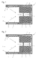
- FIG. 1 is a cross-sectional view of a hand dryer 1 according to the invention and shows a cross section in the region of the cavity 4 and perpendicular to the longitudinal sides 30 of the housing opening 3, through which the hands to be dried are inserted into the cavity 4.
- the hands are in such a way of hand dryers known manner next to each other inserted into the housing opening 3, that back of the hand and palms come to lie adjacent to each other and to the longitudinal sides 30 of the housing opening 3.
- the illustrated cross-sectional view thus corresponds, as in the following cross-sectional representations, a direction transverse to the palms, the hands would be inserted into the cavity 4.
- the dryer 1 according to the invention is largely enclosed by a housing 2, apart from the housing opening 3.
- the already mentioned cavity 4 for receiving the hands to be dried and channels for guiding the air flow within the dryer 1 are present.
- the supply air channels 8 open into two slot nozzles 9.
- These slot nozzles 9 extend substantially over the entire length of the side edges 30 of the housing opening 3. Through the slot nozzles 9, a thin air curtain is blown at high speed in the direction of the inserted into the cavity 4 to be dried hands.
- a fan 5 is present in the region of the exhaust duct 7 here.
- air is sucked out of the cavity 4 in the direction of the exhaust duct 7, from there to the supply air ducts 8 and pressed through the slit nozzles 9 back into the cavity 4.
- it is possible to circulate substantially the entire air flow through the dryer 1 therethrough.
- only part of the airflow S in the dryer 1 can be recirculated, while another part is returned to the surroundings of the dryer 1 by outlet openings, not shown in the figure.
- a means 6 for reducing the germs is arranged in the exhaust duct 7.
- the arrangement is such that essentially all of the air extracted from the cavity 4 and supplied to the exhaust air duct 7 reaches the area of action of the means 6 for the reduction of germs.
- the means 6 may be a plasma or ion source which generates a plasma or ionized gas in the region of the exhaust air duct 7, which leads to the destruction of the germs entrained in the air flow.
- a radiation source can be used whose radiation either directly leads to the destruction of germs, for example by emitting ultraviolet radiation, or whose operation causes the formation of reactive compounds in the air flow, for example the formation of ozone, reactive ionized compounds or free radicals.
- the means 6 for reducing germs may be a delivery means for a germ-reducing substance.
- it may be a nozzle that is connected to a storage container, not shown here containing the germ-reducing substance and this substance emits in the air flow.
- the germ-reducing substances directly emitted by the means 6 for reducing germs in the air flow or the substances formed in the environment around the means 6 are carried along by the air flow and conveyed through the supply air channels 8 and the nozzles 9 into the cavity 4. There, they come in contact with hands pushed into the cavity and thus contribute to the disinfection or even sterilization of the hands.
- FIG. 2 shows an alternative embodiment of a dryer according to the invention, which differs from that of the FIG. 1 by the arrangement of the means 6 for reducing germs and the device 5 for generating the air flow.
- the means 6 for reducing germs in the flow direction in front of the fan 5 is arranged.
- the mode of action corresponds completely to that of the dryer FIG. 1 ,
- FIG. 3 Another possibility of the arrangement of the means 6 for reducing germs in the air flow is in FIG. 3 shown.
- the means 6 is arranged in the cavity 4, for example in a region remote from the housing opening 3 region of the cavity 4.
- the dotted lines drawn with means 6 can additionally or alternatively in the cavity 4 attached become.
- the arrangement in the cavity 4 is particularly suitable for such means 6, whose germ-reducing effect is based, for example, on the emission of germicidal radiation in the direction of the inserted into the cavity 4 to be dried hands.
- the means 6 may therefore be, for example, a UV emitter.
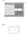
- FIG. 4 is an enlarged partial cross-section in the region of the end of a supply air duct 8 and the adjoining the supply air duct nozzle 9, which opens into the cavity 4.
- the nozzle 9 is inclined relative to the opening surface of the housing opening 3.
- the inclination is such that the air flow S is introduced through the nozzle 9 obliquely into the interior of the cavity 4.
- the angle of inclination ⁇ , with which the mouth region of the nozzle 9 and thus the air flow leaving the nozzle 9 runs obliquely to the opening surface of the housing opening 3, is preferably at least 7 °.
- the air flow is blown obliquely from behind on the hands pushed into the cavity, and the air flow pulls the adhering to the hands moisture from the back over the fingertips of the hands.
- the blown-off liquid can be removed in a manner known per se from the prior art and collected in a collecting area or collecting container.
- the dryer according to the invention is built as closed as possible.
- the housing 2 will thus usually close a larger area of the dryer to the outside than is the case in the prior art.
- a relatively open design is preferred in order to prevent a back pressure in the device, it is preferred according to the invention to guide the largest possible portion of the air flow within the dryer 1 in order to prevent germ-laden air from the dryer reaches the outside, without having passed through the means 6 for the reduction of germs.
- FIGS. 5 and 6 serve to illustrate the extent to which the cavity 4 is enclosed by a housing.
- the cavity 4 is shown here in an idealized way as a cube. However, the following considerations apply in an analogous manner to more complicated shapes.
- the total surface of the cavity 4, that is the total surface of the cube, which is in FIG. 6 is shown here results from the sum of the surfaces F1, F2, F3, F4, F5 and F6. It is a virtual total surface, since not all of the surfaces are completely surrounded by the housing 2.
- the surface of the open areas, such as the housing opening 3 with the surface F3, so the total surface of the cavity 4 are attributed.
- Shapes of the cavity are added to the non-sealed areas as those areas with which the open areas can be closed with the least possible surface area.
- the opening surface F3 of the housing opening 3, which allows access for the hands to the cavity 4 has the smallest possible surface area. So it is just so big that it allows easy access of the hands in the cavity 4.
- the opening area F3 of the housing opening is less than 20% of the total surface area (F1 + F2 + F3 + F4 + F5 + F6) of the cavity 4.
- the total opening area in the cavity 4 - thus in addition to the housing opening 3 also the other surfaces, with which the cavity opens to the environment of the dryer 1 down - is preferably less than 75% of the total surface of the cavity. Conversely, more than 25% of the total surface area of the cavity 4 is enclosed by the housing 2.
- the housing surrounds more than 35% and in particular more than 50% of the cavity. This not only improves the efficiency of the flow guide within the dryer 1, but also prevents that, to a greater extent, any germ-contaminated air may escape from the dryer 1 before passing through the germ reduction means 6.
Landscapes
- Engineering & Computer Science (AREA)
- Health & Medical Sciences (AREA)
- Public Health (AREA)
- Mechanical Engineering (AREA)
- General Engineering & Computer Science (AREA)
- Drying Of Solid Materials (AREA)
Applications Claiming Priority (1)
| Application Number | Priority Date | Filing Date | Title |
|---|---|---|---|
| DE102012008253A DE102012008253A1 (de) | 2012-04-25 | 2012-04-25 | Trockner, insbesondere Handtrockner |
Publications (2)
| Publication Number | Publication Date |
|---|---|
| EP2656762A2 true EP2656762A2 (fr) | 2013-10-30 |
| EP2656762A3 EP2656762A3 (fr) | 2014-12-10 |
Family
ID=48095509
Family Applications (1)
| Application Number | Title | Priority Date | Filing Date |
|---|---|---|---|
| EP13001815.3A Withdrawn EP2656762A3 (fr) | 2012-04-25 | 2013-04-09 | Séchoir, notamment séchoir à mains |
Country Status (4)
| Country | Link |
|---|---|
| US (1) | US20130283629A1 (fr) |
| EP (1) | EP2656762A3 (fr) |
| JP (1) | JP2013226415A (fr) |
| DE (1) | DE102012008253A1 (fr) |
Cited By (6)
| Publication number | Priority date | Publication date | Assignee | Title |
|---|---|---|---|---|
| EP2979052A4 (fr) * | 2013-03-26 | 2017-01-25 | American Dryer Inc. | Sèche-mains muni d'ensemble d'ionisation de désinfection |
| DE102015119446B3 (de) * | 2015-11-11 | 2017-03-02 | Hochschule Für Angewandte Wissenschaft Und Kunst Hildesheim/Holzminden/Göttingen | Verfahren und Vorrichtung zur Trocknung und plasmagestützten Desinfektion von Händen |
| WO2017093968A1 (fr) | 2015-12-04 | 2017-06-08 | GHENOSSIS-VAGENAS, Jean Georges | Seche-mains soufflant |
| EP3348180A1 (fr) * | 2017-01-17 | 2018-07-18 | Casares, Carlos, Maxwell | Dispositif pour éliminer des mains les germes et les bactéries |
| DE102017009637A1 (de) | 2017-10-17 | 2019-05-16 | Blv Licht- Und Vakuumtechnik Gmbh | Handtrockner mit UV-Desinfektionsvorrichtung |
| WO2022152408A1 (fr) | 2021-01-13 | 2022-07-21 | i-conel GmbH | Appareil à écoulement |
Families Citing this family (11)
| Publication number | Priority date | Publication date | Assignee | Title |
|---|---|---|---|---|
| JP6552749B2 (ja) * | 2016-08-26 | 2019-07-31 | 三菱電機株式会社 | 手乾燥装置 |
| US10455992B2 (en) | 2016-09-20 | 2019-10-29 | The Boeing Company | Hand dryer having managed air flow |
| US10264931B2 (en) * | 2016-09-23 | 2019-04-23 | The Boeing Company | Hand drying systems and methods |
| FR3066093B1 (fr) * | 2017-05-11 | 2019-06-14 | Evercleanhand | Appareil de desinfection par nebulisation |
| US12281468B2 (en) | 2020-10-13 | 2025-04-22 | Kobler Co. | Sanitization system |
| CN112515518A (zh) * | 2020-12-17 | 2021-03-19 | 安徽中科医疗器械有限公司 | 一种高效率静音负压干手器 |
| KR102429529B1 (ko) * | 2021-02-01 | 2022-08-04 | 신동혁 | 초음파 건조장치 |
| EP4221769A1 (fr) * | 2021-05-28 | 2023-08-09 | DBD Plasma GmbH | Source de plasma pour désinfection des mains |
| JP2024004238A (ja) * | 2022-06-28 | 2024-01-16 | Toto株式会社 | 手乾燥装置 |
| DE102023105836A1 (de) | 2023-03-09 | 2024-09-12 | Ille Papier-Service Gmbh | Trocknungseinrichtung und Verfahren zum Betreiben einer solchen |
| EP4633436A2 (fr) | 2023-03-09 | 2025-10-22 | Ille Papier-Service GmbH | Dispositif de séchage et procédé de fonctionnement correspondant |
Citations (1)
| Publication number | Priority date | Publication date | Assignee | Title |
|---|---|---|---|---|
| WO2007015040A1 (fr) | 2005-07-30 | 2007-02-08 | Dyson Technology Limited | Appareil de sechage |
Family Cites Families (18)
| Publication number | Priority date | Publication date | Assignee | Title |
|---|---|---|---|---|
| CH436612A (de) * | 1964-05-01 | 1967-05-31 | Ledermann Hugo | Warmlufttrockner für Hände und andere Körperteile sowie Kopfhaare |
| US3766397A (en) * | 1972-04-12 | 1973-10-16 | T Rockson | Sterilizing hand dryer |
| DE2657164A1 (de) * | 1976-12-17 | 1978-06-22 | Sprenger Albin Kg | Warmlufthaendetrockner mit temperaturgeregelter umluft |
| JPS6027295B2 (ja) * | 1979-03-26 | 1985-06-28 | マシ−ネンフアブリ−ク アド シユ−ルテス ウント コンパニ− ア−ゲ− | 手洗装置 |
| DE19513943A1 (de) * | 1995-04-12 | 1996-10-17 | Konstantin Dr Josek | Verfahren und Vorrichtung zur Verbesserung der Raumluftqualität |
| JP3624495B2 (ja) * | 1995-11-15 | 2005-03-02 | 松下電器産業株式会社 | 手乾燥装置 |
| DE19806516A1 (de) * | 1998-02-17 | 1999-08-19 | Ruediger Haaga Gmbh | Verfahren zum Sterilisieren von Behältern |
| JP2004097740A (ja) * | 2002-09-09 | 2004-04-02 | Figla Co Ltd | 手指乾燥装置 |
| JP2005177415A (ja) * | 2003-12-18 | 2005-07-07 | Yasutaka Shiraishi | オゾンによる殺菌、消毒作用を設けたハンドドライヤー |
| JP4796281B2 (ja) * | 2004-02-06 | 2011-10-19 | 財団法人工業技術研究院 | 熱風プラズマ発生装置及び熱風プラズマの手乾燥殺菌装置及び密閉式熱風プラズマ乾燥殺菌装置及び循環式熱風プラズマ消毒殺菌装置 |
| JP2005342496A (ja) * | 2004-03-08 | 2005-12-15 | Susumu Urisawa | 手指乾燥装置 |
| DE102005011701B4 (de) * | 2005-03-11 | 2008-03-13 | Stiebel Eltron Gmbh & Co. Kg | Händetrockner |
| DE202005005894U1 (de) * | 2005-04-13 | 2005-06-16 | Electrostar Schöttle GmbH & Co. KG | Gerät zum Trocknen, insbesondere von Haaren, Händen o.dgl. |
| JP2007143584A (ja) * | 2005-11-24 | 2007-06-14 | Matsushita Electric Ind Co Ltd | 手乾燥装置 |
| JP2008188143A (ja) * | 2007-02-02 | 2008-08-21 | Matsushita Electric Ind Co Ltd | 手乾燥装置 |
| WO2010015040A1 (fr) | 2008-08-07 | 2010-02-11 | Powmri Ltd | Thérapie et prévention d'une protéinopathie tdp-43 |
| JP4474483B1 (ja) * | 2009-02-06 | 2010-06-02 | シャープ株式会社 | 手乾燥装置 |
| JP4567793B2 (ja) * | 2009-02-06 | 2010-10-20 | シャープ株式会社 | 手乾燥装置 |
-
2012
- 2012-04-25 DE DE102012008253A patent/DE102012008253A1/de not_active Ceased
-
2013
- 2013-04-09 EP EP13001815.3A patent/EP2656762A3/fr not_active Withdrawn
- 2013-04-22 US US13/867,352 patent/US20130283629A1/en not_active Abandoned
- 2013-04-24 JP JP2013090990A patent/JP2013226415A/ja active Pending
Patent Citations (1)
| Publication number | Priority date | Publication date | Assignee | Title |
|---|---|---|---|---|
| WO2007015040A1 (fr) | 2005-07-30 | 2007-02-08 | Dyson Technology Limited | Appareil de sechage |
Cited By (12)
| Publication number | Priority date | Publication date | Assignee | Title |
|---|---|---|---|---|
| EP2979052A4 (fr) * | 2013-03-26 | 2017-01-25 | American Dryer Inc. | Sèche-mains muni d'ensemble d'ionisation de désinfection |
| DE102015119446B3 (de) * | 2015-11-11 | 2017-03-02 | Hochschule Für Angewandte Wissenschaft Und Kunst Hildesheim/Holzminden/Göttingen | Verfahren und Vorrichtung zur Trocknung und plasmagestützten Desinfektion von Händen |
| WO2017080864A1 (fr) | 2015-11-11 | 2017-05-18 | Hochschule Für Angewandte Wissenschaft Und Kunst Hildesheim/Holzminden/Göttingen | Procédé et dispositif de séchage et de désinfection par plasma des mains |
| US10743727B2 (en) | 2015-11-11 | 2020-08-18 | Hochschule für angewandte Wissenschaft und Kunst Hildesheim/Holzminden/Goettingen | Method of and apparatus for drying and plasma-assisted disinfection of hands |
| WO2017093968A1 (fr) | 2015-12-04 | 2017-06-08 | GHENOSSIS-VAGENAS, Jean Georges | Seche-mains soufflant |
| FR3044537A1 (fr) * | 2015-12-04 | 2017-06-09 | Philippe Roux | Seche-mains soufflant |
| CN108601490A (zh) * | 2015-12-04 | 2018-09-28 | 让·乔治·基诺西斯-瓦杰纳 | 吹风式干手器 |
| AU2016362792B2 (en) * | 2015-12-04 | 2021-07-22 | GHENOSSIS-VAGENAS, Jean Georges | Blower-type hand dryer |
| EP3348180A1 (fr) * | 2017-01-17 | 2018-07-18 | Casares, Carlos, Maxwell | Dispositif pour éliminer des mains les germes et les bactéries |
| DE102017009637A1 (de) | 2017-10-17 | 2019-05-16 | Blv Licht- Und Vakuumtechnik Gmbh | Handtrockner mit UV-Desinfektionsvorrichtung |
| WO2022152408A1 (fr) | 2021-01-13 | 2022-07-21 | i-conel GmbH | Appareil à écoulement |
| DE202021004410U1 (de) | 2021-01-13 | 2024-04-03 | Sandrier Gmbh | Strömungsgerät |
Also Published As
| Publication number | Publication date |
|---|---|
| EP2656762A3 (fr) | 2014-12-10 |
| JP2013226415A (ja) | 2013-11-07 |
| DE102012008253A1 (de) | 2013-10-31 |
| US20130283629A1 (en) | 2013-10-31 |
Similar Documents
| Publication | Publication Date | Title |
|---|---|---|
| EP2656762A2 (fr) | Séchoir, notamment séchoir à mains | |
| EP3473150B1 (fr) | Sèche-mains avec un dispositif de désinfection par uv | |
| DE69926741T2 (de) | Sterilisationsvorrichtung | |
| EP3373787B1 (fr) | Procédé et dispositif de séchage et de désinfection par plasma des mains | |
| DE3505571C2 (de) | Vorrichtung zur Desinfektion und Sterilisation von Matratzen mit Hilfe von Mikrowellen | |
| EP4072823A1 (fr) | Procédé et installation pour fabriquer et traiter des récipients en plastique stériles | |
| EP4231885A1 (fr) | Appareil à écoulement | |
| EP3730158A1 (fr) | Appareil respiratoire | |
| WO2017174169A1 (fr) | Système de décontamination | |
| WO2018007557A1 (fr) | Dispositif de désinfection et procédé de désinfection | |
| DE102021104060A1 (de) | Vorrichtung zur Desinfektion von Luft | |
| EP2676681B1 (fr) | Dispositif de nettoyage et de désinfection d'un produit destiné à être nettoyagé | |
| EP4035697A1 (fr) | Procédé et dispositif de désinfection et de stérilisation de l'air | |
| DE202005007406U1 (de) | Vorrichtung zur Reinigung und/oder Entkeimung von Matratzen | |
| DE102013000158A1 (de) | Belüftungsvorrichtung | |
| EP2258991B1 (fr) | Dispositif d'aération | |
| CH717451A1 (de) | Vorrichtung zur Beaufschlagung eines menschlichen Körpers oder von Teilen eines menschlichen Körpers mit medizinisch-kosmetischer Strahlung. | |
| DE102021105374A1 (de) | Luftaufbereitungsapparat | |
| WO2022015258A2 (fr) | Dispositif de protection par stérilisation et ensemble dispositif de protection par stérilisation | |
| WO2024033275A1 (fr) | Procédé de lutte contre des biofilms bactériens | |
| EP3901546A2 (fr) | Installation de traitement d'objets | |
| DE102021107735A1 (de) | Vorrichtung und verfahren zur desinfektion von oberflächen und raumluft | |
| DE102020124851A1 (de) | Desinfektionsverfahren und Desinfektionsvorrichtung | |
| EP4000656A2 (fr) | Dispositif et procédé de réduction de la charge en substances nocives dans un gaz | |
| DE202020103153U1 (de) | Personenluftdusche |
Legal Events
| Date | Code | Title | Description |
|---|---|---|---|
| PUAI | Public reference made under article 153(3) epc to a published international application that has entered the european phase |
Free format text: ORIGINAL CODE: 0009012 |
|
| AK | Designated contracting states |
Kind code of ref document: A2 Designated state(s): AL AT BE BG CH CY CZ DE DK EE ES FI FR GB GR HR HU IE IS IT LI LT LU LV MC MK MT NL NO PL PT RO RS SE SI SK SM TR |
|
| AX | Request for extension of the european patent |
Extension state: BA ME |
|
| PUAL | Search report despatched |
Free format text: ORIGINAL CODE: 0009013 |
|
| AK | Designated contracting states |
Kind code of ref document: A3 Designated state(s): AL AT BE BG CH CY CZ DE DK EE ES FI FR GB GR HR HU IE IS IT LI LT LU LV MC MK MT NL NO PL PT RO RS SE SI SK SM TR |
|
| AX | Request for extension of the european patent |
Extension state: BA ME |
|
| RIC1 | Information provided on ipc code assigned before grant |
Ipc: A47K 10/48 20060101AFI20141104BHEP |
|
| STAA | Information on the status of an ep patent application or granted ep patent |
Free format text: STATUS: THE APPLICATION IS DEEMED TO BE WITHDRAWN |
|
| 18D | Application deemed to be withdrawn |
Effective date: 20150611 |