EP2703105B1 - Insert de coupe et outil de coupe rotatif indexable - Google Patents
Insert de coupe et outil de coupe rotatif indexable Download PDFInfo
- Publication number
- EP2703105B1 EP2703105B1 EP12777361.2A EP12777361A EP2703105B1 EP 2703105 B1 EP2703105 B1 EP 2703105B1 EP 12777361 A EP12777361 A EP 12777361A EP 2703105 B1 EP2703105 B1 EP 2703105B1
- Authority
- EP
- European Patent Office
- Prior art keywords
- cutting edge
- cutting
- insert
- linear
- face
- Prior art date
- Legal status (The legal status is an assumption and is not a legal conclusion. Google has not performed a legal analysis and makes no representation as to the accuracy of the status listed.)
- Active
Links
Images


Classifications
-
- B—PERFORMING OPERATIONS; TRANSPORTING
- B23—MACHINE TOOLS; METAL-WORKING NOT OTHERWISE PROVIDED FOR
- B23B—TURNING; BORING
- B23B27/00—Tools for turning or boring machines; Tools of a similar kind in general; Accessories therefor
- B23B27/14—Cutting tools of which the bits or tips or cutting inserts are of special material
- B23B27/141—Specially shaped plate-like cutting inserts, i.e. length greater or equal to width, width greater than or equal to thickness
-
- B—PERFORMING OPERATIONS; TRANSPORTING
- B23—MACHINE TOOLS; METAL-WORKING NOT OTHERWISE PROVIDED FOR
- B23B—TURNING; BORING
- B23B51/00—Tools for drilling machines
-
- B—PERFORMING OPERATIONS; TRANSPORTING
- B23—MACHINE TOOLS; METAL-WORKING NOT OTHERWISE PROVIDED FOR
- B23B—TURNING; BORING
- B23B51/00—Tools for drilling machines
- B23B51/02—Twist drills
-
- B—PERFORMING OPERATIONS; TRANSPORTING
- B23—MACHINE TOOLS; METAL-WORKING NOT OTHERWISE PROVIDED FOR
- B23C—MILLING
- B23C5/00—Milling-cutters
- B23C5/16—Milling-cutters characterised by physical features other than shape
- B23C5/20—Milling-cutters characterised by physical features other than shape with removable cutter bits or teeth or cutting inserts
- B23C5/202—Plate-like cutting inserts with special form
-
- B—PERFORMING OPERATIONS; TRANSPORTING
- B23—MACHINE TOOLS; METAL-WORKING NOT OTHERWISE PROVIDED FOR
- B23B—TURNING; BORING
- B23B2200/00—Details of cutting inserts
- B23B2200/04—Overall shape
- B23B2200/0404—Hexagonal
- B23B2200/0409—Hexagonal irregular
-
- B—PERFORMING OPERATIONS; TRANSPORTING
- B23—MACHINE TOOLS; METAL-WORKING NOT OTHERWISE PROVIDED FOR
- B23B—TURNING; BORING
- B23B2200/00—Details of cutting inserts
- B23B2200/04—Overall shape
- B23B2200/0404—Hexagonal
- B23B2200/0419—Hexagonal trigonal
-
- B—PERFORMING OPERATIONS; TRANSPORTING
- B23—MACHINE TOOLS; METAL-WORKING NOT OTHERWISE PROVIDED FOR
- B23B—TURNING; BORING
- B23B2200/00—Details of cutting inserts
- B23B2200/04—Overall shape
- B23B2200/0423—Irregular
-
- B—PERFORMING OPERATIONS; TRANSPORTING
- B23—MACHINE TOOLS; METAL-WORKING NOT OTHERWISE PROVIDED FOR
- B23B—TURNING; BORING
- B23B2200/00—Details of cutting inserts
- B23B2200/12—Side or flank surfaces
- B23B2200/125—Side or flank surfaces discontinuous
-
- B—PERFORMING OPERATIONS; TRANSPORTING
- B23—MACHINE TOOLS; METAL-WORKING NOT OTHERWISE PROVIDED FOR
- B23B—TURNING; BORING
- B23B2200/00—Details of cutting inserts
- B23B2200/20—Top or side views of the cutting edge
- B23B2200/201—Details of the nose radius and immediately surrounding area
-
- B—PERFORMING OPERATIONS; TRANSPORTING
- B23—MACHINE TOOLS; METAL-WORKING NOT OTHERWISE PROVIDED FOR
- B23B—TURNING; BORING
- B23B2200/00—Details of cutting inserts
- B23B2200/28—Angles
- B23B2200/283—Negative cutting angles
-
- B—PERFORMING OPERATIONS; TRANSPORTING
- B23—MACHINE TOOLS; METAL-WORKING NOT OTHERWISE PROVIDED FOR
- B23B—TURNING; BORING
- B23B2200/00—Details of cutting inserts
- B23B2200/28—Angles
- B23B2200/286—Positive cutting angles
-
- B—PERFORMING OPERATIONS; TRANSPORTING
- B23—MACHINE TOOLS; METAL-WORKING NOT OTHERWISE PROVIDED FOR
- B23B—TURNING; BORING
- B23B2205/00—Fixation of cutting inserts in holders
- B23B2205/12—Seats for cutting inserts
-
- B—PERFORMING OPERATIONS; TRANSPORTING
- B23—MACHINE TOOLS; METAL-WORKING NOT OTHERWISE PROVIDED FOR
- B23B—TURNING; BORING
- B23B2251/00—Details of tools for drilling machines
- B23B2251/50—Drilling tools comprising cutting inserts
-
- Y—GENERAL TAGGING OF NEW TECHNOLOGICAL DEVELOPMENTS; GENERAL TAGGING OF CROSS-SECTIONAL TECHNOLOGIES SPANNING OVER SEVERAL SECTIONS OF THE IPC; TECHNICAL SUBJECTS COVERED BY FORMER USPC CROSS-REFERENCE ART COLLECTIONS [XRACs] AND DIGESTS
- Y10—TECHNICAL SUBJECTS COVERED BY FORMER USPC
- Y10T—TECHNICAL SUBJECTS COVERED BY FORMER US CLASSIFICATION
- Y10T407/00—Cutters, for shaping
- Y10T407/19—Rotary cutting tool
- Y10T407/1906—Rotary cutting tool including holder [i.e., head] having seat for inserted tool
-
- Y—GENERAL TAGGING OF NEW TECHNOLOGICAL DEVELOPMENTS; GENERAL TAGGING OF CROSS-SECTIONAL TECHNOLOGIES SPANNING OVER SEVERAL SECTIONS OF THE IPC; TECHNICAL SUBJECTS COVERED BY FORMER USPC CROSS-REFERENCE ART COLLECTIONS [XRACs] AND DIGESTS
- Y10—TECHNICAL SUBJECTS COVERED BY FORMER USPC
- Y10T—TECHNICAL SUBJECTS COVERED BY FORMER US CLASSIFICATION
- Y10T407/00—Cutters, for shaping
- Y10T407/23—Cutters, for shaping including tool having plural alternatively usable cutting edges
- Y10T407/235—Cutters, for shaping including tool having plural alternatively usable cutting edges with integral chip breaker, guide or deflector
-
- Y—GENERAL TAGGING OF NEW TECHNOLOGICAL DEVELOPMENTS; GENERAL TAGGING OF CROSS-SECTIONAL TECHNOLOGIES SPANNING OVER SEVERAL SECTIONS OF THE IPC; TECHNICAL SUBJECTS COVERED BY FORMER USPC CROSS-REFERENCE ART COLLECTIONS [XRACs] AND DIGESTS
- Y10—TECHNICAL SUBJECTS COVERED BY FORMER USPC
- Y10T—TECHNICAL SUBJECTS COVERED BY FORMER US CLASSIFICATION
- Y10T407/00—Cutters, for shaping
- Y10T407/24—Cutters, for shaping with chip breaker, guide or deflector
-
- Y—GENERAL TAGGING OF NEW TECHNOLOGICAL DEVELOPMENTS; GENERAL TAGGING OF CROSS-SECTIONAL TECHNOLOGIES SPANNING OVER SEVERAL SECTIONS OF THE IPC; TECHNICAL SUBJECTS COVERED BY FORMER USPC CROSS-REFERENCE ART COLLECTIONS [XRACs] AND DIGESTS
- Y10—TECHNICAL SUBJECTS COVERED BY FORMER USPC
- Y10T—TECHNICAL SUBJECTS COVERED BY FORMER US CLASSIFICATION
- Y10T408/00—Cutting by use of rotating axially moving tool
- Y10T408/89—Tool or Tool with support
- Y10T408/905—Having stepped cutting edges
-
- Y—GENERAL TAGGING OF NEW TECHNOLOGICAL DEVELOPMENTS; GENERAL TAGGING OF CROSS-SECTIONAL TECHNOLOGIES SPANNING OVER SEVERAL SECTIONS OF THE IPC; TECHNICAL SUBJECTS COVERED BY FORMER USPC CROSS-REFERENCE ART COLLECTIONS [XRACs] AND DIGESTS
- Y10—TECHNICAL SUBJECTS COVERED BY FORMER USPC
- Y10T—TECHNICAL SUBJECTS COVERED BY FORMER US CLASSIFICATION
- Y10T408/00—Cutting by use of rotating axially moving tool
- Y10T408/89—Tool or Tool with support
- Y10T408/909—Having peripherally spaced cutting edges
Definitions
- the present invention relates to a cutting insert used for a tool for cutting and an indexable rotary cutting tool using this cutting tool.
- a so-called positive cutting insert having a relief angle formed on a side face is known.
- the benefit of the positive cutting insert is that a cutting insert of the same format can be used for each of cutting of an outermost region of a hole to be machined and cutting of a central region of the hole to be machined (See Japanese Patent Laid-Open No. 2003-62712 , for example).
- a cutting edge on a side of a short side is used for the cutting of the outermost region of the hole to be machined, while a cutting edge on a side of a long side is used for the cutting of the central region of the hole to be machined.
- Document EP 1 749 602 A2 is considered to be the prior art closest to the subject-matter of claim 1 and discloses a plate-like cutting insert comprising: a substantially polygonal upper face;a substantially polygonal lower face; and a plurality of side faces extending between the upper face and the lower face, wherein,the cutting insert comprises a first cutting edge formed at an intersection portion where the upper face and the plurality of side faces intersect with each other; a chip breaker for the first cutting edge is formed on the upper face; the first cutting edge comprises at least one corner cutting edge formed at a corner portion of the upper face, and at least one linear cutting edge formed linearly; the plurality of side faces comprise at least one main side face including a plane constituting a flank of the at least one linear cutting edge, and at least one sub side face constituting a flank of the at least one corner cutting edge; the at least one main side face comprises a relief angle of 0°; the at least one sub side face comprises a relief angle larger than 0°; the cutting insert comprises at least one second cutting
- a chip breaker for the cutting edge for cutting the outermost region of the hole and the chip breaker for the cutting edge for cutting the central region of the hole are both formed on an upper face. Therefore, it is difficult to design a chip breaker having a shape for optimizing cutting efficiency of the respective cutting edges. That is, an area on the upper face of the cutting insert is limited, and if the chip breaker for one of the cutting edges is designed optimally, the degree of freedom of an area and a depth in designing the chip breaker for the other cutting edge deteriorates, and optimal designing of the other chip breaker might not be possible. In some cases, it is likely that discharge efficiency of chips of the other chip breaker deteriorates conversely.
- One of objects of the present invention is to provide a cutting insert capable of designing an optimal shape for each of the chip breaker for the cutting edge used for cutting of the outermost region of the hole to be machined and the chip breaker for the cutting edge used for cutting of the central region of the hole, and to provide an indexable rotary cutting tool using this cutting insert.
- a cutting insert of the present invention is a plate-like cutting insert (1) according to claim 1.
- the indexable rotary cutting tool of the present invention is an indexable rotary cutting tool (10) provided with a plurality of the above cutting inserts (1) in a tool body (11), wherein:
- the chip breaker of each cutting edge can be formed by being separated to the upper face and the lower face. As a result, optimal designing of the chip breaker for the respective cutting edges is made possible.
- a cutting insert of the embodiment is used for an indexable drill and the great feature of this cutting insert is that rake faces having different use applications are formed on both an upper face and a lower face, respectively.
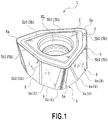
- the cutting insert 1 of the embodiment is a plate-like body having an upper face 2 with a substantially hexagonal shape and a lower face 3 with a substantially enneagonal shape, and a mounting hole HL for being attached to a tool body penetrating the upper face 2 and the lower face 3 is formed at a center part of the upper face 2 and the lower face 3.
- a part of the upper face 2 of the cutting insert 1 functions as a rake face when the cutting insert 1 is used for cutting an outermost region of a hole.
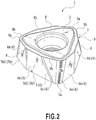
- a part of the lower face 3 facing the upper face 2 functions as a rake face when the cutting insert 1 is used for cutting a central region of the hole.
- a plurality of side faces 4 extending between the upper face 2 and the lower face 3 functions as a flank.
- An outer cutting edge 5 is formed over an entire region of an intersection portion between the upper face 2 and the flank 4.
- the outer cutting edge 5 is a cutting edge for cutting the outermost region of the hole.
- the outer cutting edge 5 includes three corner cutting edges 5a formed at corner portions of the upper face 2 and curved, and two linear cutting edges (5b1 and 5b2) arranged between the two corner cutting edges 5a and connected to each other. One of end portions of each of the two linear cutting edges (5b1 and 5b2) is connected to the other corner cutting edges 5a, respectively. More specifically, the corner cutting edge 5a and the two linear cutting edges 5b, indicated by a portion surrounded by a broken line in Fig. 3 constitute one cutting edge group. Therefore, the outer cutting edge 5 is constituted by three cutting edge groups.
- the two linear cutting edges (5b1 and 5b2) belonging to one cutting edge group include first and second linear cutting edges 5b1 and 5b2.
- the first linear cutting edge 5b1 and the second linear cutting edge 5b2 intersect with each other at an obtuse angle.
- a length L1 of the first linear cutting edge 5b1 is larger than a length L2 of the second linear cutting edge 5b2.
- the outer shape of the upper face 2 is 120° rotationally symmetric with respect to a central axis line C1 of the mounting hole HL.
- the outer shape of the upper face 2 is a bilaterally asymmetric shape without a symmetric axis line in any direction on top view illustrated in Fig. 3A . It should be noted that the benefit of the outer shape of this upper face 2 will be described later.
- the plurality of faces 4 constituting the flank forming the plurality of the above-described cutting edges has different sizes of relief angles in accordance with the corresponding cutting edges.
- the side face 4m functioning as a flank forming the two linear cutting edges 5b1 and 5b2 has a relief angle of 0°.
- this side face will be referred to as a main side face 4m.
- the main side face 4m is orthogonal to a reference face of the upper face 2 and the lower face 3 (that is, a face orthogonal to the central axis line C1).
- the main side face 4m includes a plane.
- the relief angle of the side face 4s connected to the corner cutting edge 5a is ⁇ ° ( ⁇ > 0°).
- this side face will be referred to as a sub side face 4s.
- the sub side face 4s is inclined in a direction closer to the central axis line C1 of the cutting insert 1 from the upper face 2 to the lower face 3.
- an inner cutting edge 8 is formed at an intersection portion 9 between each main side face 4m and the lower face 3. Therefore, the inner cutting edge 8 is formed only in a region connected to the main side face 4m in the intersection portion 9 where the lower face 3 and the plurality of side faces 4 intersect with each other and is not formed in a region connected to the sub side face 4s.
- the inner cutting edge 8 is a cutting edge for cutting the central region of the machined hole and is a cutting edge for cutting mainly a region not cut by the outer cutting edge 5.
- a chip breaker 6 for the outer cutting edge 5 which will be described later is formed, while on the lower face 3, a chip breaker 7 for the inner cutting edge 8 which will be described later is formed.
- the chip breaker 6 for the outer cutting edge 5 has a groove width larger than the chip breaker 7 for the inner cutting edge 8 and is formed shallow as is known from Figs. 1 to 4 .
- the outer cutting edge 5 is formed on the upper face 2 and the inner cutting edge 8 is formed on the lower face 3, and thus, when the shape of a chip breaker for one of the cutting edges is to be designed, it is not necessary to consider the specification of the chip breaker for the other cutting edge. That is, since only the outer cutting edge 5 is formed on the upper face 2, the entire upper face 2 can be used only for the design of the chip breaker 6 suitable for cutting of an outer periphery. Similarly, since only the inner cutting edge 8 is formed on the lower face 3, the entire lower face 3 can be used only for the design of the chip breaker 7 suitable for cutting of the center. That is, the cutting insert 1 is capable of independently designing the two types of the chip breakers for the two types of the cutting edges having different cutting regions.
- the indexable rotary cutting tool such as a drill to which the cutting insert 1 is applied has further improved chip discharge performances including dividing of chips into small pieces, than before.
- the size of the rake face is relatively small, it was necessary to take into consideration the relationship between the two types of the chip breakers previously, but since there is no such need for the cutting insert 1, the cutting insert 1 is effective when it is used for an indexable drill for a relatively small machined hole diameter and the like.
- the cutting insert 1 is provided with both the outer cutting edge 5 and the inner cutting edge 8. Therefore, it can be used 3 times as an insert for cutting the outermost region of the hole and 3 times as an insert for cutting the central region of the hole, that is, 6 times in total.
- an accidental defect caused in the outer cutting edge 5 does not affect the number of times of use as the insert for cutting the central region of the hole. Naturally, the same applies to the other case where the accidental defect is caused in the inner cutting edge 8.
- a radial rake can be arranged at 0° or an orthonormal angle in the same way as the positive cutting insert. That is because when the cutting insert 1 is arranged at a radial rake of 0°, a portion which should essentially have interfered with an inner wall of the machined hole in the case of a negative insert corresponds to the sub side face 4s to which a relief angle is given and the sub side face 4s and the inner wall of the machined hole do not interfere with each other. Then, due to the arrangement at a radial rake of 0°, a load on the outer cutting edge 5 is reduced, and an accidental defect becomes difficult to occur.
- the cutting insert 1 when the cutting insert 1 is arranged at a radial rake of 0° or a positive angle, generated chips separate away from a direction toward the inner wall of the machined hole in comparison with the case where the cutting insert 1 is arranged at a negative radial rake angle. Therefore, the chips enter into the chip discharge groove smoothly without excessively making contact with the inner wall of the machined hole and are easily discharged.
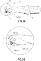
- indexable rotary cutting tool of the present invention will be described using an example of an indexable drill.
- This indexable drill (hereinafter referred to as a "drill 10") is, as illustrated to Figs. 5A to 6B , constituted by attaching the above-described cutting insert 1 to the two insert seats 12 formed at a leading end of the tool body 11.
- a twisted chip discharge grooves 13 13a, 13b are formed, and generated chips are discharged to the outside of the hole through the grooves.
- the insert seat 12 in the drill 10 is provided with two types of insert seats, that is, a insert seat when the cutting insert 1 is used for the outermost region cutting of the hole (hereinafter referred to as an "outer insert seat 12a”) and a insert seat when the cutting insert 1 is used for the central region cutting of the hole (hereinafter referred to as a "center-side insert seat 12b”) .
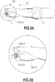
- the outer insert seat 12a is a position used in the case where the lower face 3 faces a bottom face of the outer insert seat 12a and the cutting insert 1 is arranged so that the outer cutting edge 5 is involved in cutting.
- the center-side insert seat 12b is a position used in the case where the upper face 2 faces a bottom face of the center-side insert seat 12b and the cutting insert 1 is arranged so that the inner cutting edge 8 is involved in cutting.
- a rotation trajectory drawn by each ridge line of the sub side face 4s corresponding to the inner cutting edge 8 involved in the cutting and being located closest to the side of the axis of rotation of the tool body overlaps with the rotation trajectory drawn by the outer cutting edge 5 of the cutting insert 1 arranged so that the outer cutting edge 5 is involved in the cutting. That is, as illustrated in Fig. 4 , when the cutting insert is arranged with the lower face 2 up, one of top portions is directed to a root direction of the tool body 11 as in the case of the figure. At this time, a portion 14 surrounded by a dotted line does not function as a cutting edge.
- the cutting insert 1 needs to be arranged so that the rotation trajectory of this portion 14 is within a cutting region of the outer cutting edge 5 (a region swept by the outer cutting edge 5 when the tool makes a rotation) . If the portion 14 is located outside the cutting region of the outer cutting edge 5, an uncut position is caused on a bottom of the machined hole. In order to avoid such situation, the arranging method of the cutting insert 1 with the lower face 2 up is adjusted. That is, the cutting insert 1 is arranged so that the region swept by the line obtained by projecting the portion 14 onto the bottom of the machined hole is contained within the cutting region of the outer cutting edge 5.
- intersection portion 9 defining the outer shape of the lower face 3 where the lower face 3 and the plurality of side faces intersect with each other the intersection portion connected to the sub side face 4s has a linear portion 9b and a curved portion 9a.
- the cutting insert is arranged so that one of the plurality of linear portions 9b becomes parallel to an axis of rotation AX1 of the tool body 11 (See Fig. 4 ).
- the bottom face of the outer insert seat 12a is formed so to have a shape matching the outer shape of the upper face 2 of the cutting insert 1 (outer profile shape of Fig. 3 ) with the upper face 2 up with respect to the bottom face
- the bottom face of the center-side insert seat 12b is formed so to have a shape matching the outer shape of the upper face 2 of the cutting insert 1 (outer profile shape of Fig. 4 ) with the upper face 2 down with respect to the bottom face.
- the outer shape of the upper face 2 is bilaterally asymmetric on top view, the outer shape of the top view of the bottom face of the outer insert seat 12a and the outer shape of the top view of the bottom face of the center-side insert seat 12b are different from each other.
- the cutting insert 1 when the cutting insert 1 is to be attached to the outer insert seat 12a or the center-side insert seat 12b in an improper direction, the cutting insert 1 cannot be attached to each of the insert seats. Specifically, even when the cutting insert 1 is to be attached in a direction in which the bottom face of the outer insert seat 12a and the upper face 2 of the cutting insert 1 face each other or even when the cutting insert 1 is to be attached in a direction in which the bottom face of the center-side insert seat 12b and the lower face 3 of the cutting insert 1 face each other, the attachment is not possible.
- the axial rakes of the two cutting inserts 1 being both negative, loads applied to the both cutting inserts 1 are balanced, and the drill 10 rotates stably.
- accuracy of a machined hole diameter is enhanced.
- occurrence of chattering vibration is suppressed and a quality of the hole to be machined is improved.
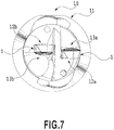
- Fig. 7 is a diagram of leading-end view of the drill 10.
- the chip discharge grooves 13 have shapes different from each other. That is, the chip discharge groove 13a on the outer insert seat 12a has a shape of an approximately 1/4 arc on the leading-edge view, while a groove face (thinning face) including a curved face having an appropriate length from the leading end is formed in a groove wall close to the center of the chip discharge groove 13b on the center-side insert seat 12b (See Figs. 6A and 6B ).
- the chips discharged from the cutting insert arranged on each insert seat can be discharged to the rear end side of the tool body 11 efficiently, and rigidity of the drill 10 is ensured at the same time.
- a cutting insert according to a second embodiment of the present invention will be described by referring to Figs. 8A to 10 .
- Figs. 8 are partial enlarged views illustrated by enlarging one of cutting edge groups constituting the outer cutting edge of the cutting insert of the embodiment.
- a cutting insert 1A according to the embodiment as illustrated in Fig.
- the corner cutting edge 5a is constituted by an arc-shaped cutting edge 5d3 arranged on a top portion, a first short cutting edge 5d1 extending from one of end portions of this arc-shaped cutting edge 5d3, and a second short cutting edge 5d2 extending from the other end portion.
- a virtual plane bisecting an angle formed by a virtual extension (m) of the first short cutting edge 5d1 and a virtual extension (n) of the second short cutting edge 5d2 and orthogonal to the upper face 2 is assumed to be (p).
- An intersection between this virtual plane (p) and the arc-shaped cutting edge 5d3 is assumed to be (z).
- the intersection (z) is located outside the intersection (W). That is, the intersection (z) is located farther than the intersection (W) with respect to the central axis line C1.
- a first long cutting edge As illustrated in Fig. 8B , in the cutting insert 1A of the embodiment, when viewed from a direction perpendicular to a main side face 4m1 corresponding to the linear cutting edge connected to the first short cutting edge 5d1 (hereinafter referred to as a "first long cutting edge") 5f1, an intersection line CN1 between the main side face 4m1 and a sub side face 4s1 corresponding to the first short cutting edge 5d1 is orthogonal to the first long cutting edge 5f1.
- an intersection line CN2 between the main side face 4m2 and a sub side face 4s2 including the second short cutting edge 5d2 is orthogonal to the second long cutting edge 5f2.
- each cutting edge group has the above-described shape and the cutting insert 1A is formed by connecting those cutting edge groups to each other. That is, the flanks of the first long cutting edge 5f1 and the second long cutting edge 5f2 of the cutting insert 1 are formed so that the relief angle is 0°. The flanks of the first short cutting edge 5d1 and the second short cutting edge 5d2 of the corner cutting edge 5a of the cutting insert 1A are formed so that the relief angle exceeds 0°.
- the cutting edge group being configured having such shape, strength of the corner cutting edge 5a is improved from the cutting insert 1 of the first embodiment.
- the cutting insert 1A of the embodiment there is no limitation on an intersecting angle between the first long cutting edge 5f1 and the first short cutting edge 5d1 and an intersecting angle between the second long cutting edge 5f2 and the second short cutting edge 5d2. Therefore, for example, as illustrated in Fig. 9 , shapes can be employed in which the first long cutting edge 5f1 and the first short cutting edge 5d1 are arranged linearly and the second long cutting edge 5f2 and the second short cutting edge 5d2 intersect with each other at an obtuse angle. In this case, the relief to the hole wall, that is, an interval between the hole wall and the cutting insert 1B is largely ensured, and biting of the generated chips is prevented.
- the cutting insert 1 has a shape in which it can be attached to both drills of right rotation and left rotation and can generate divided chips.
- intersection line CN1 or the intersection line CN2 is not required to be present explicitly, but may be a rounded connection portion extending between the upper face 2 and the lower face 3. That is, the connection portion may be appropriately rounded, to thereby prevent a defect in the ridge line. In such a case, the roundness is ignored, and a virtual intersection line obtained by extending the main side face 4m1 and the sub side face 4s1, respectively, and a virtual intersection line obtained by extending the main side face 4m2 and the sub side face 4s2, respectively, are set to be the intersection line CN1 or the intersection line CN2.
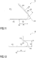
- Fig. 11 is a partial enlarged view illustrated by enlarging one of the cutting edge groups of the cutting insert of the embodiment.
- a distance (R) from a first virtual line (Q) passing through an intersection portion (connection portion) between the first long cutting edge 5f1 and the first short cutting edge 5d1 and being perpendicular to the first long cutting edge 5f1 to an intersection portion (connection portion) between the arc-shaped cutting edge 5d3 and the second short cutting edge 5d2 is larger than a distance (T) from a second virtual line (S) passing through an intersection portion (connection portion) between the second long cutting edge 5f2 and the second short cutting edge 5d2 and being perpendicular to the second long cutting edge 5f2, to an intersection portion between the arc-shaped cutting edge 5d3 and the first short cutting edge 5d1.
- the cutting edge group being configured having such a shape, cutting resistance is reduced.
- a cutting insert 1E can be formed so as to have a shape in which the first long cutting edge 5f1 and the first short cutting edge 5d1 are arranged linearly, and the second long cutting edge 5f2 and the second short cutting edge 5d2 intersect with each other at an obtuse angle.
- the cutting edge group is configured having such shapes, the cutting resistance is reduced and relief to the hole wall, that is, an interval between the hole wall and the cutting insert 1 is largely ensured, and thus biting of generated chips is prevented.
- a shape is also possible in which the first long cutting edge 5f1 and the first short cutting edge 5d1 intersect with each other at an obtuse angle and the second long cutting edge 5f2 and the second short cutting edge 5d2 intersect with each other at an obtuse angle. In this case, the cutting resistance is reduced and also, divided chips can be generated.
- the cutting insert and the indexable rotary cutting tool of the present invention are not limited to the above-described embodiments.
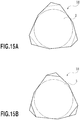
- the profile shapes of the upper face and the lower face of the cutting insert there can also be employed another polygonal shape instead of the above-described substantially triangular shape, or a shape in which the middle of a side is bent as in the case of a cutting insert 1G illustrated in Figs. 14A and 14B and a cutting insert 1H illustrated in Figs. 15A and 15B .
- the indexable rotary cutting tool of the present invention arrangement is not limited to that in which the cutting insert has a radial rake of 0°. That is, the arrangement method of the cutting insert can be changed as appropriate in accordance with the type of a work material. For example, when cast iron whose chips can be easily divided into small pieces is to be machined, the radial rake can be intentionally made negative in order to give priority to cutting edge strength. If the size of the radial rake is within a range of -5° and more and +5° or less, the indexable rotary cutting tool of the present invention can handle almost every type of a work material sufficiently.
- the above-described indexable drill is of a double cutting edge type, but the number of the cutting edges may be 3 or more.
- the tool body needs one or more outer insert seats and one or more center-side insert seats. The other insert seats are adjusted as appropriate so that the cutting edge fills a gap between the outer periphery and the center.
- the indexable rotary cutting tool is not limited to the drill, but a cutting tool for plunging or a cutting tool used by being pressed in a main spindle direction of an end mill attached with a bottom edge and the like can also be used.
Landscapes
- Engineering & Computer Science (AREA)
- Mechanical Engineering (AREA)
- Milling Processes (AREA)
- Drilling Tools (AREA)
- Cutting Tools, Boring Holders, And Turrets (AREA)
Claims (15)
- Insert de coupe en forme de plaquette (1) comprenant :une face supérieure (2) sensiblement polygonale ;une face inférieure (3) sensiblement polygonale ; etune pluralité de faces latérales (4m, 4s) s'étendant entre la face supérieure (2) et la face inférieure (3), oùla plaquette de coupe (1) comprend une première arête de coupe (5) formée sur une partie d'intersection où la face supérieure (2) et la pluralité de faces latérales (4m, 4s) se croisent ;un brise-copeaux (6) pour la première arête de coupe (5) est formé sur la face supérieure (2) ;la première arête de coupe (5) comprend au moins une arête de coupe de coin (5a) formée sur une partie de coin de la face supérieure (2) et incurvée, et au moins une arête de coupe linéaire (5b) formée linéairement ;la pluralité de faces latérales (4m, 4s) comprend au moins une face latérale principale (4m) présentant un plan constituant un flanc de ladite au moins une arête de coupe linéaire (5b), et au moins une face latérale secondaire (4s) constituant un flanc de ladite au moins une arête de coupe de coin (5a);ladite au moins une face latérale principale (4m) comprend un angle de dépouille de 0°;ladite au moins une face latérale secondaire (4s) comprend un angle de dépouille supérieur à 0°;la plaquette de coupe (1) comprend au moins une deuxième arête de coupe (8) formée sur la partie d'intersection où ladite au moins une face latérale principale (4m) et la face inférieure (3) se croisent ;un brise-copeaux (7) pour la deuxième arête de coupe (8) est formé sur la face inférieure (3) ; etune forme extérieure de la face supérieure (2) et une forme extérieure de la face inférieure (3) diffèrent l'une de l'autre.
- Plaquette de coupe selon la revendication 1, où
la première arête de coupe (5) comprend trois ensembles d'arêtes de coupe comprenant une arête de coupe de coin (5a) et une arête de coupe linéaire (5b). - Plaquette de coupe selon la revendication 1 ou la revendication 2, où la première arête de coupe (5) est formée sur toute la surface d'une partie d'intersection entre la face supérieure (2) et la pluralité de faces latérales (4) ;
la première arête de coupe (5) est constituée d'une pluralité de groupes d'arêtes de coupe agencées avec une symétrie de révolution ;
la deuxième arête de coupe (8) n'est formée que dans une surface reliée à la face latérale principale (4m) dans la partie d'intersection (9) où la face inférieure (3) et la pluralité de faces latérales (4) se croisent. - Plaquette de coupe selon l'une des revendications 1 à 3, où
le brise-copeaux (6) pour la première arête de coupe (5) et le brise-copeaux (7) pour la deuxième arête de coupe (8) sont configurés indépendamment l'un de l'autre. - Plaquette de coupe selon l'une des revendications 1 à 4, où
la plaquette de coupe est prévue pour être utilisée dans un foret indexable de type à double arête de coupe comprenant une arête de coupe extérieure et une arête de coupe intérieure,
la première arête de coupe (5) est prévue pour servir d'arête de coupe extérieure ; et
la deuxième arête de coupe (8) est prévue pour servir d'arête de coupe intérieure. - Plaquette de coupe selon la revendication 1 ou la revendication 2, où ladite au moins une arête de coupe de coin (5a) comprend une arête de coupe en forme d'arc (5d3), une première arête de coupe courte (5d1) raccordée à une des parties d'extrémité de l'arête de coupe en forme d'arc (5d3), et une deuxième arête de coupe courte (5d2) raccordée à l'autre partie d'extrémité de l'arête de coupe en forme d'arc (5d3) ;
en vue en plan, une intersection (z) entre un plan virtuel (p) partageant en deux un angle formé par la première arête de coupe courte (5d1) et la deuxième arête de coupe courte (5d2) et orthogonale à la face supérieure et à l'arête de coupe en forme d'arc (5d3) est plus proche qu'une intersection (w) entre le plan virtuel (p) et la partie d'intersection (9) entre la pluralité de faces latérales (4m, 4s) et la face inférieure (3) par rapport à une ligne d'axe central (C1) de la plaquette de coupe (1), et en vue dans une direction perpendiculaire à la face latérale principale (4ml) comprenant une arête de coupe linéaire (5f1) raccordée à la première arête de coupe courte (5d1), une ligne d'intersection (CN1) entre la face latérale principale (4ml) et la face latérale secondaire (4s1) comprenant la première arête de coupe courte (5d1) est orthogonale à l'arête de coupe linéaire (5f1), et en vue dans une direction perpendiculaire à la face latérale principale (4m2) correspondant à l'arête de coupe linéaire (5f2) raccordée à la deuxième arête de coupe courte (5d2), une ligne d'intersection (CN2) entre la face latérale principale (4m2) et la face latérale secondaire (4s2) correspondant à la deuxième arête de coupe courte (5d2) est orthogonale à l'arête de coupe linéaire (5f2). - Plaquette de coupe selon la revendication 1, où
ladite au moins une arête de coupe de coin comprend une arête de coupe en forme d'arc (5d3), une première arête de coupe courte (5d1) raccordée à une des parties d'extrémité de l'arête de coupe en forme d'arc (5d3), et une deuxième arête de coupe courte (5d2) raccordée à l'autre partie d'extrémité de l'arête de coupe en forme d'arc (5d3) ; en vue en plan, une distance (R) d'une première ligne virtuelle (Q) passant par une partie d'intersection entre une arête de coupe linéaire (5f1) raccordée à la première arête de coupe courte (5d1) et la première arête de coupe courte (5dl) et perpendiculaire à l'arête de coupe linéaire (5f1), à une partie d'intersection entre l'arête de coupe en forme d'arc (5d3) et la deuxième arête de coupe courte (5d2), est supérieure à une distance (T) d'une deuxième ligne virtuelle (S) passant par une partie d'intersection entre l'arête de coupe linéaire (5f2) raccordée à la deuxième arête de coupe courte (5d2) et la deuxième arête de coupe courte (5d2) et perpendiculaire à la deuxième arête de coupe courte (5d2), à une partie d'intersection entre l'arête de coupe en forme d'arc (5d3) et la première arête de coupe courte (5dl). - Plaquette de coupe selon l'une des revendications 1 à 7, où
ladite au moins une arête de coupe linéaire (5b) comprend une première et une deuxième arêtes de coupe linéaires (5b1, 5b2) reliées l'une à l'autre, un angle formé par la première et la deuxième arêtes de coupe linéaires (5b1, 5b2) est un angle obtus, et les longueurs (L1, L2) diffèrent l'une de l'autre. - Plaquette de coupe selon la revendication 2, où
l'arête de coupe linéaire (5b) est constituée par la première et la deuxième arêtes de coupe linéaires (5b1, 5b2) reliées l'une à l'autre, les longueurs (L1, L2) de la première et de la deuxième arêtes de coupe linéaires (5b1, 5b2) diffèrent l'une de l'autre, et en vue en plan, un angle formé par celles-ci est un angle obtus, la première et la deuxième arêtes de coupe linéaires (5b1, 5b2) sont reliées à des arêtes de coupe de coin (5a) différentes, et une forme extérieure de la face supérieure (2) en vue en plan est à symétrie de révolution sur 120° par rapport à une ligne d'axe central (C1) de la plaquette de coupe (1). - Plaquette de coupe selon l'une des revendications 6 à 8, où
ladite au moins une arête de coupe de coin (5a) comprend une première à une troisième arêtes de coupe de coin (5a), ladite au moins une arête de coupe linéaire (5b) formée entre deux arêtes de coupe de coin (5a) arbitraires de la première to troisième arêtes de coupe de coin (5a) est constituée par la première et la deuxième arêtes de coupe linéaires (5b1, 5b2) reliées l'une à l'autre, les longueurs (L1, L2) de la première et de la deuxième arêtes de coupe linéaires (5b1, 5b2) diffèrent l'une de l'autre, et en vue en plan, un angle formé par celles-ci est un angle obtus, et une forme extérieure de la face supérieure (2) formée par la première à la troisième arêtes de coupe de coin (5a) et la première et la deuxième arêtes de coupe linéaires (5b1, 5b2) correspondant à la première à la troisième arêtes de coupe de coin (5a) est à symétrie de révolution sur 120° par rapport à une ligne d'axe central (C1) de la plaquette de coupe (1). - Outil de coupe rotatif indexable pourvu de deux ou de plusieurs des plaquettes de coupe selon l'une des revendications 1 à 10 dans un corps d'outil, où :au moins une plaquette de coupe est agencée de telle manière qu'une deuxième arête de coupe (8) est impliquée dans la coupe ; etdans les faces latérales secondaires (4s) de la plaquette de coupe (1) agencée de telle manière que la deuxième arête de coupe (8) est impliquée dans la coupe, une trajectoire de rotation effectuée par chaque ligne de crête de la face latérale secondaire (4s) reliée à la deuxième arête de coupe (8) impliquée dans la coupe et la plus proche du côté central du corps d'outil (10) chevauche une trajectoire de rotation effectuée par la première arête de coupe (5) de la plaquette de coupe (1) agencée de telle manière que la première arête de coupe (5) est impliquée dans la coupe.
- Outil de coupe rotatif indexable selon la revendication 11, où,
dans la partie d'intersection (9) où la face inférieure (3) et la pluralité de faces latérales (4m, 4s) se croisent, une forme extérieure de la face inférieure (3) de la plaquette de coupe (1) est définie, agencée de telle manière que la deuxième arête de coupe (8) est impliquée dans la coupe, la partie d'intersection reliée à la face latérale secondaire (4s) présente une partie linéaire (9b) et une partie incurvée (9a), et l'agencement est tel qu'une partie linéaire d'une pluralité de parties linéaires (9b) devient parallèle à un axe de rotation (AX1) du corps d'outil (11). - Outil de coupe rotatif indexable selon la revendication 11 ou la revendication 12, où toutes les plaquettes de coupe (1) fixées au corps d'outil (11) sont fixées de telle manière qu'un angle de coupe axial devient négatif.
- Outil de coupe rotatif indexable selon l'une des revendications 11 à 13, où,
dans la pluralité de plaquette de coupes (1), au moins une des plaquettes de coupe (1) agencée de telle manière que la première arête de coupe (5) est impliquée dans la coupe est agencée de telle manière qu'un angle de coupe radial devient égal ou supérieur à 0°. - Outil de coupe rotatif indexable selon l'une des revendications 11 à 14, où
sur une face latérale du corps d'outil (11), une première et une deuxième rainures d'évacuation de copeaux (13a, 13b) sont formées, et la première et la deuxième rainures d'évacuation de copeaux, (13a, 13b) ont des formes différentes l'une de l'autre.
Applications Claiming Priority (2)
| Application Number | Priority Date | Filing Date | Title |
|---|---|---|---|
| JP2011097771 | 2011-04-26 | ||
| PCT/JP2012/061180 WO2012147836A1 (fr) | 2011-04-26 | 2012-04-26 | Insert de coupe et outil de coupe rotatif du type à pointe remplaçable |
Publications (3)
| Publication Number | Publication Date |
|---|---|
| EP2703105A1 EP2703105A1 (fr) | 2014-03-05 |
| EP2703105A4 EP2703105A4 (fr) | 2014-10-15 |
| EP2703105B1 true EP2703105B1 (fr) | 2019-06-05 |
Family
ID=47072351
Family Applications (1)
| Application Number | Title | Priority Date | Filing Date |
|---|---|---|---|
| EP12777361.2A Active EP2703105B1 (fr) | 2011-04-26 | 2012-04-26 | Insert de coupe et outil de coupe rotatif indexable |
Country Status (4)
| Country | Link |
|---|---|
| US (1) | US9370833B2 (fr) |
| EP (1) | EP2703105B1 (fr) |
| JP (1) | JP5696782B2 (fr) |
| WO (1) | WO2012147836A1 (fr) |
Families Citing this family (10)
| Publication number | Priority date | Publication date | Assignee | Title |
|---|---|---|---|---|
| US10029317B2 (en) * | 2012-09-20 | 2018-07-24 | Tungaloy Corporation | Cutting insert and cutting edge replaceable rotary cutting tool |
| WO2015005357A1 (fr) * | 2013-07-08 | 2015-01-15 | 株式会社タンガロイ | Plaquette de coupe et outil de coupe |
| KR101845366B1 (ko) * | 2014-01-28 | 2018-04-04 | 미츠비시 히타치 쓰루 가부시키가이샤 | 인서트 및 날끝 교환식 회전 절삭 공구 |
| EP3117938B1 (fr) * | 2014-04-22 | 2021-08-04 | Tungaloy Corporation | Plaquette de coupe et outil de coupe |
| JP6696181B2 (ja) * | 2016-01-13 | 2020-05-20 | 三菱マテリアル株式会社 | 切削インサートおよび刃先交換式切削工具 |
| JP6758604B2 (ja) * | 2016-09-21 | 2020-09-23 | 株式会社タンガロイ | 切削インサート及びその製造方法 |
| JP2018051717A (ja) * | 2016-09-30 | 2018-04-05 | 株式会社タンガロイ | 切削インサート |
| TWI825040B (zh) * | 2017-11-30 | 2023-12-11 | 以色列商艾斯卡公司 | 單側三向可轉位銑削嵌件、刀具固持器及包括嵌件及刀具固持器的嵌件式銑刀 |
| TWI787381B (zh) | 2017-11-30 | 2022-12-21 | 以色列商艾斯卡公司 | 單側三向可轉位切削嵌件及其嵌件式銑刀 |
| EP3769886A1 (fr) * | 2019-07-24 | 2021-01-27 | Walter Ag | Insert de découpe indexable |
Family Cites Families (28)
| Publication number | Priority date | Publication date | Assignee | Title |
|---|---|---|---|---|
| JPS5254075Y2 (fr) * | 1971-04-30 | 1977-12-07 | ||
| DE2834083A1 (de) * | 1978-08-03 | 1980-02-21 | Walter Gmbh Montanwerke | Bohrer mit wendeplattenbestueckung |
| JPH0135777Y2 (fr) * | 1985-05-25 | 1989-11-01 | ||
| SE463658B (sv) * | 1987-10-19 | 1991-01-07 | Seco Tools Ab | Skaer foer svarvning |
| JPH0735702Y2 (ja) * | 1988-03-10 | 1995-08-16 | 三菱マテリアル株式会社 | 転削工具 |
| US5114282A (en) * | 1988-03-21 | 1992-05-19 | Gte Valenite Corporation | Indexable insert for roughing and finishing |
| US4930945A (en) | 1988-05-20 | 1990-06-05 | Mitsubishi Metal Corporation | Insert rotary cutter |
| US4954021A (en) * | 1988-06-10 | 1990-09-04 | Mitsubishi Metal Corporation | Inserted rotary cutter |
| US5226761A (en) * | 1991-09-27 | 1993-07-13 | Iscar Ltd. | Metal cutting insert and metal cutting tool utilizing the metal cutting insert |
| SE504315C2 (sv) * | 1994-05-09 | 1997-01-13 | Sandvik Ab | Borr för metallborrning |
| JP3317490B2 (ja) * | 1998-06-18 | 2002-08-26 | 日立ツール株式会社 | 高送りスローアウェイ式回転工具 |
| DE10040612A1 (de) * | 2000-08-16 | 2002-02-28 | Komet Stahlhalter Werkzeuge | Schneidplatte für drehende Werkzeuge |
| DE10138896A1 (de) * | 2001-08-08 | 2003-02-20 | Sandvik Ab | Schneideinsatz zum Fräsen und Fräswerkzeug |
| JP4701562B2 (ja) | 2001-08-23 | 2011-06-15 | 株式会社タンガロイ | スローアウェイドリル用の切刃チップ |
| DE10230452B4 (de) * | 2002-07-06 | 2005-07-21 | Fette Gmbh | Planfräser |
| SE527378C2 (sv) | 2003-05-08 | 2006-02-21 | Sandvik Intellectual Property | Skär för svarvning försett med en eggfas |
| JP4677747B2 (ja) * | 2004-09-07 | 2011-04-27 | 三菱マテリアル株式会社 | インサートおよびスローアウェイ式切削工具 |
| DE102005025815A1 (de) * | 2005-06-02 | 2006-12-07 | Kennametal Widia Produktions Gmbh & Co. Kg | Schneideinsatz, insbesondere zur Kurbelwellenbearbeitung |
| JP4231496B2 (ja) * | 2005-08-01 | 2009-02-25 | 住友電工ハードメタル株式会社 | スローアウェイチップ |
| US7278805B2 (en) * | 2005-10-03 | 2007-10-09 | Kennametal Inc. | Cutting insert for effective chip control |
| SE529979C2 (sv) * | 2006-01-30 | 2008-01-22 | Sandvik Intellectual Property | Borr och borrskär där mynningsytan i skärets hål har en tvärsnittsvis konvexform |
| DE102006024131A1 (de) * | 2006-05-22 | 2007-11-29 | Sandvik Intellectual Property Ab | Schneideinsatz mit Planschneide, insbesondere für Planfräser |
| SE530316C2 (sv) * | 2006-09-25 | 2008-04-29 | Sandvik Intellectual Property | Verktyg och skär där det ena skäret har en primär och en sekundär förstärkt delegg som genomskär den genererade |
| EP2514544B1 (fr) * | 2007-06-14 | 2020-09-09 | TaeguTec Ltd. | Corps de foret pour un foret |
| KR101516826B1 (ko) * | 2008-03-31 | 2015-05-04 | 미쓰비시 마테리알 가부시키가이샤 | 드릴용 인서트 및 인서트 드릴 |
| SE533269C2 (sv) * | 2008-12-17 | 2010-08-03 | Sandvik Intellectual Property | Dubbelsidigt, indexerbart planfrässkär |
| US7976250B2 (en) * | 2009-02-12 | 2011-07-12 | Tdy Industries, Inc. | Double-sided cutting inserts for high feed milling |
| JP2013006221A (ja) * | 2009-10-13 | 2013-01-10 | Mitsubishi Materials Corp | 切削インサート及び刃先交換式回転工具 |
-
2012
- 2012-04-26 EP EP12777361.2A patent/EP2703105B1/fr active Active
- 2012-04-26 WO PCT/JP2012/061180 patent/WO2012147836A1/fr not_active Ceased
- 2012-04-26 JP JP2013512424A patent/JP5696782B2/ja active Active
-
2013
- 2013-02-03 US US13/757,837 patent/US9370833B2/en active Active
Non-Patent Citations (1)
| Title |
|---|
| None * |
Also Published As
| Publication number | Publication date |
|---|---|
| EP2703105A1 (fr) | 2014-03-05 |
| WO2012147836A1 (fr) | 2012-11-01 |
| US9370833B2 (en) | 2016-06-21 |
| JPWO2012147836A1 (ja) | 2014-07-28 |
| EP2703105A4 (fr) | 2014-10-15 |
| US20130170915A1 (en) | 2013-07-04 |
| JP5696782B2 (ja) | 2015-04-08 |
Similar Documents
| Publication | Publication Date | Title |
|---|---|---|
| EP2703105B1 (fr) | Insert de coupe et outil de coupe rotatif indexable | |
| JP5361891B2 (ja) | 切削インサートおよび切削工具並びにそれを用いた切削方法 | |
| JP6241636B2 (ja) | 切削インサートおよび刃先交換式切削工具 | |
| US9168601B2 (en) | Multi-flute reamer and cutting insert therefor | |
| JP4597270B2 (ja) | 切削インサートおよび切削工具並びにそれを用いた切削方法 | |
| US10029317B2 (en) | Cutting insert and cutting edge replaceable rotary cutting tool | |
| CN105188999B (zh) | 切削刀片和刀尖更换式切削工具 | |
| CN108472751B (zh) | 切削刀片及可转位刀片式切削工具 | |
| JP4981810B2 (ja) | 切削インサートおよびこれを用いる切削工具、並びに切削方法 | |
| CN104718039B (zh) | 带冷却孔的立铣刀 | |
| US20130071192A1 (en) | End mill | |
| JP4981811B2 (ja) | 切削インサートおよびこれを用いる切削工具、並びに切削方法 | |
| EP2832484A1 (fr) | Fraise en bout sphérique | |
| JP6365701B2 (ja) | 切削インサート及び刃先交換式切削工具 | |
| CN112703076A (zh) | 切削工具 | |
| JP5988010B2 (ja) | 切削インサート、工具ボデーおよび切削工具 | |
| US20160193668A1 (en) | Insert for drill and cutting blade replacement-type drill | |
| JP2011156608A (ja) | 切削インサート | |
| JP6014427B2 (ja) | 切削インサート並びにそれを用いた切削工具 | |
| JP6057010B1 (ja) | 穴あけ工具 | |
| CN117042903B (zh) | 切削刀片及切削刀具 | |
| JP2004195572A (ja) | リーマ | |
| JP2006082136A (ja) | スローアウェイ式回転工具及びその製造方法 | |
| JP2003170308A (ja) | スローアウェイチップおよびスローアウェイ式ドリル |
Legal Events
| Date | Code | Title | Description |
|---|---|---|---|
| PUAI | Public reference made under article 153(3) epc to a published international application that has entered the european phase |
Free format text: ORIGINAL CODE: 0009012 |
|
| 17P | Request for examination filed |
Effective date: 20131023 |
|
| AK | Designated contracting states |
Kind code of ref document: A1 Designated state(s): AL AT BE BG CH CY CZ DE DK EE ES FI FR GB GR HR HU IE IS IT LI LT LU LV MC MK MT NL NO PL PT RO RS SE SI SK SM TR |
|
| DAX | Request for extension of the european patent (deleted) | ||
| A4 | Supplementary search report drawn up and despatched |
Effective date: 20140917 |
|
| RIC1 | Information provided on ipc code assigned before grant |
Ipc: B23B 27/14 20060101ALI20140911BHEP Ipc: B23B 51/04 20060101AFI20140911BHEP Ipc: B23C 5/20 20060101ALI20140911BHEP |
|
| RIC1 | Information provided on ipc code assigned before grant |
Ipc: B23B 51/00 20060101AFI20180725BHEP Ipc: B23B 27/14 20060101ALI20180725BHEP |
|
| GRAP | Despatch of communication of intention to grant a patent |
Free format text: ORIGINAL CODE: EPIDOSNIGR1 |
|
| STAA | Information on the status of an ep patent application or granted ep patent |
Free format text: STATUS: GRANT OF PATENT IS INTENDED |
|
| INTG | Intention to grant announced |
Effective date: 20180911 |
|
| GRAJ | Information related to disapproval of communication of intention to grant by the applicant or resumption of examination proceedings by the epo deleted |
Free format text: ORIGINAL CODE: EPIDOSDIGR1 |
|
| STAA | Information on the status of an ep patent application or granted ep patent |
Free format text: STATUS: REQUEST FOR EXAMINATION WAS MADE |
|
| GRAS | Grant fee paid |
Free format text: ORIGINAL CODE: EPIDOSNIGR3 |
|
| STAA | Information on the status of an ep patent application or granted ep patent |
Free format text: STATUS: GRANT OF PATENT IS INTENDED |
|
| GRAP | Despatch of communication of intention to grant a patent |
Free format text: ORIGINAL CODE: EPIDOSNIGR1 |
|
| INTC | Intention to grant announced (deleted) | ||
| INTG | Intention to grant announced |
Effective date: 20190212 |
|
| GRAA | (expected) grant |
Free format text: ORIGINAL CODE: 0009210 |
|
| STAA | Information on the status of an ep patent application or granted ep patent |
Free format text: STATUS: THE PATENT HAS BEEN GRANTED |
|
| AK | Designated contracting states |
Kind code of ref document: B1 Designated state(s): AL AT BE BG CH CY CZ DE DK EE ES FI FR GB GR HR HU IE IS IT LI LT LU LV MC MK MT NL NO PL PT RO RS SE SI SK SM TR |
|
| REG | Reference to a national code |
Ref country code: GB Ref legal event code: FG4D |
|
| REG | Reference to a national code |
Ref country code: CH Ref legal event code: EP |
|
| REG | Reference to a national code |
Ref country code: AT Ref legal event code: REF Ref document number: 1139501 Country of ref document: AT Kind code of ref document: T Effective date: 20190615 |
|
| REG | Reference to a national code |
Ref country code: DE Ref legal event code: R096 Ref document number: 602012060741 Country of ref document: DE |
|
| REG | Reference to a national code |
Ref country code: IE Ref legal event code: FG4D |
|
| REG | Reference to a national code |
Ref country code: NL Ref legal event code: MP Effective date: 20190605 |
|
| REG | Reference to a national code |
Ref country code: LT Ref legal event code: MG4D |
|
| PG25 | Lapsed in a contracting state [announced via postgrant information from national office to epo] |
Ref country code: AL Free format text: LAPSE BECAUSE OF FAILURE TO SUBMIT A TRANSLATION OF THE DESCRIPTION OR TO PAY THE FEE WITHIN THE PRESCRIBED TIME-LIMIT Effective date: 20190605 Ref country code: NO Free format text: LAPSE BECAUSE OF FAILURE TO SUBMIT A TRANSLATION OF THE DESCRIPTION OR TO PAY THE FEE WITHIN THE PRESCRIBED TIME-LIMIT Effective date: 20190905 Ref country code: ES Free format text: LAPSE BECAUSE OF FAILURE TO SUBMIT A TRANSLATION OF THE DESCRIPTION OR TO PAY THE FEE WITHIN THE PRESCRIBED TIME-LIMIT Effective date: 20190605 Ref country code: HR Free format text: LAPSE BECAUSE OF FAILURE TO SUBMIT A TRANSLATION OF THE DESCRIPTION OR TO PAY THE FEE WITHIN THE PRESCRIBED TIME-LIMIT Effective date: 20190605 Ref country code: LT Free format text: LAPSE BECAUSE OF FAILURE TO SUBMIT A TRANSLATION OF THE DESCRIPTION OR TO PAY THE FEE WITHIN THE PRESCRIBED TIME-LIMIT Effective date: 20190605 Ref country code: SE Free format text: LAPSE BECAUSE OF FAILURE TO SUBMIT A TRANSLATION OF THE DESCRIPTION OR TO PAY THE FEE WITHIN THE PRESCRIBED TIME-LIMIT Effective date: 20190605 Ref country code: FI Free format text: LAPSE BECAUSE OF FAILURE TO SUBMIT A TRANSLATION OF THE DESCRIPTION OR TO PAY THE FEE WITHIN THE PRESCRIBED TIME-LIMIT Effective date: 20190605 |
|
| PG25 | Lapsed in a contracting state [announced via postgrant information from national office to epo] |
Ref country code: RS Free format text: LAPSE BECAUSE OF FAILURE TO SUBMIT A TRANSLATION OF THE DESCRIPTION OR TO PAY THE FEE WITHIN THE PRESCRIBED TIME-LIMIT Effective date: 20190605 Ref country code: LV Free format text: LAPSE BECAUSE OF FAILURE TO SUBMIT A TRANSLATION OF THE DESCRIPTION OR TO PAY THE FEE WITHIN THE PRESCRIBED TIME-LIMIT Effective date: 20190605 Ref country code: GR Free format text: LAPSE BECAUSE OF FAILURE TO SUBMIT A TRANSLATION OF THE DESCRIPTION OR TO PAY THE FEE WITHIN THE PRESCRIBED TIME-LIMIT Effective date: 20190906 Ref country code: BG Free format text: LAPSE BECAUSE OF FAILURE TO SUBMIT A TRANSLATION OF THE DESCRIPTION OR TO PAY THE FEE WITHIN THE PRESCRIBED TIME-LIMIT Effective date: 20190905 |
|
| REG | Reference to a national code |
Ref country code: AT Ref legal event code: MK05 Ref document number: 1139501 Country of ref document: AT Kind code of ref document: T Effective date: 20190605 |
|
| PG25 | Lapsed in a contracting state [announced via postgrant information from national office to epo] |
Ref country code: CZ Free format text: LAPSE BECAUSE OF FAILURE TO SUBMIT A TRANSLATION OF THE DESCRIPTION OR TO PAY THE FEE WITHIN THE PRESCRIBED TIME-LIMIT Effective date: 20190605 Ref country code: SK Free format text: LAPSE BECAUSE OF FAILURE TO SUBMIT A TRANSLATION OF THE DESCRIPTION OR TO PAY THE FEE WITHIN THE PRESCRIBED TIME-LIMIT Effective date: 20190605 Ref country code: PT Free format text: LAPSE BECAUSE OF FAILURE TO SUBMIT A TRANSLATION OF THE DESCRIPTION OR TO PAY THE FEE WITHIN THE PRESCRIBED TIME-LIMIT Effective date: 20191007 Ref country code: EE Free format text: LAPSE BECAUSE OF FAILURE TO SUBMIT A TRANSLATION OF THE DESCRIPTION OR TO PAY THE FEE WITHIN THE PRESCRIBED TIME-LIMIT Effective date: 20190605 Ref country code: NL Free format text: LAPSE BECAUSE OF FAILURE TO SUBMIT A TRANSLATION OF THE DESCRIPTION OR TO PAY THE FEE WITHIN THE PRESCRIBED TIME-LIMIT Effective date: 20190605 Ref country code: AT Free format text: LAPSE BECAUSE OF FAILURE TO SUBMIT A TRANSLATION OF THE DESCRIPTION OR TO PAY THE FEE WITHIN THE PRESCRIBED TIME-LIMIT Effective date: 20190605 Ref country code: RO Free format text: LAPSE BECAUSE OF FAILURE TO SUBMIT A TRANSLATION OF THE DESCRIPTION OR TO PAY THE FEE WITHIN THE PRESCRIBED TIME-LIMIT Effective date: 20190605 |
|
| PG25 | Lapsed in a contracting state [announced via postgrant information from national office to epo] |
Ref country code: IS Free format text: LAPSE BECAUSE OF FAILURE TO SUBMIT A TRANSLATION OF THE DESCRIPTION OR TO PAY THE FEE WITHIN THE PRESCRIBED TIME-LIMIT Effective date: 20191005 Ref country code: SM Free format text: LAPSE BECAUSE OF FAILURE TO SUBMIT A TRANSLATION OF THE DESCRIPTION OR TO PAY THE FEE WITHIN THE PRESCRIBED TIME-LIMIT Effective date: 20190605 |
|
| REG | Reference to a national code |
Ref country code: DE Ref legal event code: R097 Ref document number: 602012060741 Country of ref document: DE |
|
| PG25 | Lapsed in a contracting state [announced via postgrant information from national office to epo] |
Ref country code: TR Free format text: LAPSE BECAUSE OF FAILURE TO SUBMIT A TRANSLATION OF THE DESCRIPTION OR TO PAY THE FEE WITHIN THE PRESCRIBED TIME-LIMIT Effective date: 20190605 |
|
| PLBE | No opposition filed within time limit |
Free format text: ORIGINAL CODE: 0009261 |
|
| STAA | Information on the status of an ep patent application or granted ep patent |
Free format text: STATUS: NO OPPOSITION FILED WITHIN TIME LIMIT |
|
| PG25 | Lapsed in a contracting state [announced via postgrant information from national office to epo] |
Ref country code: PL Free format text: LAPSE BECAUSE OF FAILURE TO SUBMIT A TRANSLATION OF THE DESCRIPTION OR TO PAY THE FEE WITHIN THE PRESCRIBED TIME-LIMIT Effective date: 20190605 Ref country code: DK Free format text: LAPSE BECAUSE OF FAILURE TO SUBMIT A TRANSLATION OF THE DESCRIPTION OR TO PAY THE FEE WITHIN THE PRESCRIBED TIME-LIMIT Effective date: 20190605 |
|
| 26N | No opposition filed |
Effective date: 20200306 |
|
| PG25 | Lapsed in a contracting state [announced via postgrant information from national office to epo] |
Ref country code: SI Free format text: LAPSE BECAUSE OF FAILURE TO SUBMIT A TRANSLATION OF THE DESCRIPTION OR TO PAY THE FEE WITHIN THE PRESCRIBED TIME-LIMIT Effective date: 20190605 |
|
| PG25 | Lapsed in a contracting state [announced via postgrant information from national office to epo] |
Ref country code: MC Free format text: LAPSE BECAUSE OF FAILURE TO SUBMIT A TRANSLATION OF THE DESCRIPTION OR TO PAY THE FEE WITHIN THE PRESCRIBED TIME-LIMIT Effective date: 20190605 |
|
| REG | Reference to a national code |
Ref country code: CH Ref legal event code: PL |
|
| PG25 | Lapsed in a contracting state [announced via postgrant information from national office to epo] |
Ref country code: LU Free format text: LAPSE BECAUSE OF NON-PAYMENT OF DUE FEES Effective date: 20200426 Ref country code: FR Free format text: LAPSE BECAUSE OF NON-PAYMENT OF DUE FEES Effective date: 20200430 Ref country code: CH Free format text: LAPSE BECAUSE OF NON-PAYMENT OF DUE FEES Effective date: 20200430 Ref country code: LI Free format text: LAPSE BECAUSE OF NON-PAYMENT OF DUE FEES Effective date: 20200430 |
|
| REG | Reference to a national code |
Ref country code: BE Ref legal event code: MM Effective date: 20200430 |
|
| PG25 | Lapsed in a contracting state [announced via postgrant information from national office to epo] |
Ref country code: BE Free format text: LAPSE BECAUSE OF NON-PAYMENT OF DUE FEES Effective date: 20200430 |
|
| GBPC | Gb: european patent ceased through non-payment of renewal fee |
Effective date: 20200426 |
|
| PG25 | Lapsed in a contracting state [announced via postgrant information from national office to epo] |
Ref country code: IE Free format text: LAPSE BECAUSE OF NON-PAYMENT OF DUE FEES Effective date: 20200426 Ref country code: GB Free format text: LAPSE BECAUSE OF NON-PAYMENT OF DUE FEES Effective date: 20200426 |
|
| PG25 | Lapsed in a contracting state [announced via postgrant information from national office to epo] |
Ref country code: MT Free format text: LAPSE BECAUSE OF FAILURE TO SUBMIT A TRANSLATION OF THE DESCRIPTION OR TO PAY THE FEE WITHIN THE PRESCRIBED TIME-LIMIT Effective date: 20190605 Ref country code: CY Free format text: LAPSE BECAUSE OF FAILURE TO SUBMIT A TRANSLATION OF THE DESCRIPTION OR TO PAY THE FEE WITHIN THE PRESCRIBED TIME-LIMIT Effective date: 20190605 |
|
| PG25 | Lapsed in a contracting state [announced via postgrant information from national office to epo] |
Ref country code: MK Free format text: LAPSE BECAUSE OF FAILURE TO SUBMIT A TRANSLATION OF THE DESCRIPTION OR TO PAY THE FEE WITHIN THE PRESCRIBED TIME-LIMIT Effective date: 20190605 |
|
| PGFP | Annual fee paid to national office [announced via postgrant information from national office to epo] |
Ref country code: DE Payment date: 20250422 Year of fee payment: 14 |
|
| PGFP | Annual fee paid to national office [announced via postgrant information from national office to epo] |
Ref country code: IT Payment date: 20260320 Year of fee payment: 15 |