EP2703216A2 - Structure de véhicule utilitaire avec sécurisation de charge pour le fonctionnement à deux niveaux - Google Patents
Structure de véhicule utilitaire avec sécurisation de charge pour le fonctionnement à deux niveaux Download PDFInfo
- Publication number
- EP2703216A2 EP2703216A2 EP13181124.2A EP13181124A EP2703216A2 EP 2703216 A2 EP2703216 A2 EP 2703216A2 EP 13181124 A EP13181124 A EP 13181124A EP 2703216 A2 EP2703216 A2 EP 2703216A2
- Authority
- EP
- European Patent Office
- Prior art keywords
- double
- decker
- commercial vehicle
- rails
- load securing
- Prior art date
- Legal status (The legal status is an assumption and is not a legal conclusion. Google has not performed a legal analysis and makes no representation as to the accuracy of the status listed.)
- Granted
Links
Images




Classifications
-
- B—PERFORMING OPERATIONS; TRANSPORTING
- B60—VEHICLES IN GENERAL
- B60P—VEHICLES ADAPTED FOR LOAD TRANSPORTATION OR TO TRANSPORT, TO CARRY, OR TO COMPRISE SPECIAL LOADS OR OBJECTS
- B60P7/00—Securing or covering of load on vehicles
- B60P7/06—Securing of load
- B60P7/135—Securing or supporting by load bracing means
- B60P7/15—Securing or supporting by load bracing means the load bracing means comprising a movable bar
Definitions
- the invention relates to a commercial vehicle body, in particular box body of a commercial vehicle, in particular a truck, trailer and / or semitrailer, with a cargo space and at least one side wall, wherein the side wall has at least two vertically extending and the cargo space open double-decker rails.
- Commercial vehicles for transporting goods by road have suitable commercial vehicle bodies for receiving the goods.
- the commercial vehicles in question are in particular lorry trailers and / or semitrailers.
- the commercial vehicle superstructures can be, for example, tarpaulin bodies or box bodies.
- the cargo space is closed at least laterally by tarpaulins.
- Tarpaulin structures in which the lateral tarpaulins can be slid in the longitudinal direction of the utility vehicle are also referred to as curtainsider bodies.
- the cargo space of box bodies is also enclosed laterally by solid walls. These are usually designed in the form of sandwich panels and have outer cover layers and an interposed core layer, such as a foamed plastic, on.
- Box bodies which can be quickly picked up by a trailer chassis and separated again, are referred to as Konkoffer inconvenienceten and have legs, with the help of the Konkoffer excessiveten can be parked on the ground at a height that allows driving under the truck bodies by a trailer chassis for the purpose of receiving the exchangeable cargo bodies.
- the commercial vehicle superstructures can be flexibly loaded depending on the goods to be transported, these are partially equipped with so-called double-deck rails.
- These vertically extending and distributed at predetermined intervals in the longitudinal direction of the utility vehicle arranged double-decker rails serve to accommodate so-called double-decker beams at different heights.
- the double-decker beams then extend transversely of the commercial vehicle from a double-decker rail to an opposite double-decker rail on the other side wall.
- the double-deck rails are spaced according to the width or length of standard pallets, so that a standard pallet can be placed on two adjacent double-decker beams. In this way, standard pallets can be loaded on several levels one above the other to make the most efficient use of the cargo space.
- the type and attachment of the double-deck rails according to the invention is particularly in the DE EP 2 116 448 A1 why this description is also made by reference to the subject of the present description in terms of a preferred embodiment.
- the double-deck rails are usually embedded in the side walls in order to make full use of the width of the cargo space.
- the double - level rails also serve both to lock the double - decker bars in the desired height as well as the guidance of the double-decker beams when moving from one height to another height.
- load-securing rails in which load-securing means such as tension belts or the like can be fastened.
- load-securing rails When attaching the load securing rails, a compromise must be made between easy loading and cost-effective production of the commercial vehicle.
- the invention is therefore based on the object, the commercial vehicle bodies of the type mentioned above and described in more detail above and further develop that the known disadvantages can be taken into account.
- the double-deck rails are used not only for mounting the double-decker beams, but also for mounting the load securing beam.
- the load securing beams are fixed in different heights in the double-deck rails and / or lockable. In this way it is achieved that the mounting height of the load securing beam can be adapted to the mounting height of the double decker beams to achieve regardless of the mounting height of the double decker beams a simple and secure load securing the parked on the double decker beams goods.
- the load securing bar is not necessarily coupled to the simultaneous use of double-decker bars.
- the load securing beams can also be used to secure loads of goods parked on the floor of the commercial vehicle body.
- the at least one load securing beam in the double deck rails can be fixed or locked at different heights.
- two or more load securing bars can be fixed one above the other at the at least one side wall, for example in order to secure particularly heavy goods against slipping or overturning.
- the load securing beams are not only lockable in different heights, but also guided in the height adjustment in the double-decker rails.
- This guide can be achieved by a positive connection transverse to the double-deck rails, for example along and / or transverse to the commercial vehicle.
- a load securing bar extends in the assembled state of a double-decker rail to another double-deck rail of the same side wall.
- the number of load securing bars can vary as a whole.
- Several load securing bars can be arranged one above the other and or in the longitudinal direction of the utility vehicle next to each other. The same applies to the double-decker beams.
- double-level rails can in principle be all vertical rails of the sidewall of the commercial vehicle body which are open towards the loading space. Accordingly, the double-deck rails also need not necessarily be provided for receiving double-decker beams. The double-deck rails may also be provided for receiving other equipment of the commercial vehicle.
- the double-decker rails can be provided and designed to set certain load securing elements on the side wall adjustable in height. This can serve, for example, to secure the load or merely to stow away the cargo securing elements safely if these are not used. The load securing elements can thus damage neither the goods to be transported nor the commercial vehicle body.
- double-decker rails are actually provided and designed for receiving and adjusting the height of double-decker bars.
- these double-decker rails can accommodate the forces required to secure loads with the aid of the load-securing bars and / or enable safe double-deck operation of the commercial vehicle body. Therefore, for the sake of simplicity and ease of understanding, the term double-decker rail will continue to be described, without any inconvenient distinction between a double-decker rail in the narrow sense and another vertical rail open to the cargo space of at least one side wall. The term double-decker rail will therefore continue to be used, even though it may have a broader meaning according to the invention than it sometimes has in practice.
- a double-decker bar is vertically displaceably received in at least one of the double-deck rails in addition to the load securing bar and held fixed at different heights.
- a double-decker bar is vertically displaceably accommodated in each of the two double-decker rails accommodating at least one load-securing bar and can be held fixed at different heights.
- the double-deck rails have a T-slot open to the loading space.
- the groove of the double-decker rail has undercuts and is at least partially T-shaped in cross-section. It is structurally simple when the double-deck rail has the opening to the loading space narrowing ribs.
- the load-securing bar and / or at least one double-decker bar can then be held behind the ribs of the T-slot in the T-slot.
- the corresponding form-fitting preferably prevents the load-securing bar and / or the at least one double-decker bar from being pulled out of it accidentally perpendicular to the double-deck bar.
- the load securing bar and / or the at least one double-decker bar can be moved easily and reliably along a double-decker rail without accidentally disengaging from the double-decker rail
- the load securing bar and / or the at least one double-decker bar may comprise at least one push-in bar for engaging in a double-decker rail for engaging behind the undercuts or ribs of the double-decker rail.
- the double-decker rail has an insertion opening for the load-securing bar and / or the double-decker bar.
- the load-securing bar and / or the at least one double-decker beams, in particular the corresponding Schiebling be inserted into the double-decker rail and / or taken out of the double-decker rail.
- the insertion opening is provided at one end, preferably the lower end of the double-decker rail. In this case, the insertion opening can be created for the sake of simplicity that the pointing to the loading space opening of the double-decker rail in the region of the insertion opening is wider.
- a slide can then be easily brought, for example, in an undercut the undercuts of the double-decker rail position.
- the double-deck beams and the load-securing beams for insertion into the double-deck rails need not be raised excessively.
- the Schiebling has at least partially a T-shaped cross-section.
- the Schiebling engages behind the ribs of the double-deck rails, so as to counteract accidental withdrawal of the Schieblings from the double-decker rail.
- the slide can be designed in a simple manner as a slider.
- the Schiebling then slips due to its shape along the double-deck rail to the desired position, why the Schiebling can have rounded edges or the like.
- the possibly rubbing surfaces are smooth and the slide is made of a plastic.
- the friction between the Schiebling and the double-decker rail can also be reduced by the fact that the Schiebling is formed in the form of a wheel which roll when moving the Schieblings along the double-decker rail on a flank of the double-decker rail, between the groove base and the ribs in the region of the opening to the loading space can. It is particularly preferred if the axis of rotation of the wheel extends approximately perpendicular to the side wall.
- the wheel is also preferably so large that it can engage behind the undercuts of the double-decker rail.
- the slide-on may also have a roller associated with a particular flank of the double-decker rail for unwinding on that flank when the push-slide is displaced along the double-decker rail.
- a plurality of rollers per slide can be provided, which can be assigned to different flanks or ribs of the double-deck rail.
- the load-securing bar is designed to be telescopic.
- the slide can be designed to be adjustable along the load securing beam. Such adjustability can be provided longitudinally or transversely to the load securing bar.
- the double-decker rails may have recesses. These recesses may, if necessary, have uniform spacing along the double-deck rails. This achieves a uniform height grid. Alternatively or additionally, the recesses can serve a positive engagement of the load securing beams and / or the double-decker beams so that they can not accidentally slip down the double-decker rails.
- the load securing beam and / or the double-decker beam has a locking element for engaging and supporting in at least one recess of the double-decker rail.
- the engagement of the locking element in the recess can preferably lead to a positive connection in a vertical direction down.
- the locking elements of the load securing bar are adjustable from the mounting position to a positioning position.
- the load securing bar is then preferably displaceable longitudinally of the double-deck rails held in the same. It is particularly simple and reliable, when the locking elements are moved during adjustment of the mounting position in the positioning position and back perpendicular to the double-deck rails.
- the adjustment of the load securing bar along the double floor rails can be simplified if the locking elements of the load securing bar are coupled to an operating unit with which the locking elements can be moved from the mounting position to the positioning position and back. It offers itself from a constructive point of view and the ease of handling because of, to form the control unit as a hand lever.
- the locking elements and / or the operating unit is spring-loaded in the direction of the positioning position of the locking elements, it can be ensured in a simple manner that the locking elements change back into the mounting position after shifting the load securing beam and fix the load securing beam in the double-deck rails.
- the load-securing bar adjacent to at least one side wall may have a scuff guard.
- the side wall is preferably harder than the scuff plate.
- the scuff plates can be mounted easily replaceable. As favorable bead-like scuff plates and / or scouring strips made of plastic have proven.
- the basic form of the load securing bar is formed by at least two partial profiles. These are basically inexpensive to manufacture and easy to connect.
- a commercial vehicle N in the form of a semitrailer with a commercial vehicle body 1 in the form of a box body is shown.
- the commercial vehicle body 1 comprises an end wall 2, a rear wall 3, a roof 4, two side walls 5, 6 and a bottom 7.
- the side walls 5, 6, the end wall 2 and the roof 4 are designed as sandwich panels. These include outer cover layers of metal, preferably steel, between which a core layer of a foamed plastic is arranged.
- double-rail 8 inserted into the side walls 5,6 extending in the vertical direction and each have fixed predetermined distances in the horizontal direction.
- a double-decker bar 9 is mounted in each case.
- a load securing bar 10 is mounted in both double-decker rails 8. While the double deck beams 10 extend transversely of the commercial vehicle body 1, the load securing bar 10 extends in the longitudinal direction of the commercial vehicle body 1.
- the double deck beams 9 are adapted to receive the ends of two adjacent standard pallets. But it can also be provided close to each other two double-decker rails.
- adjacent double-decker beams and adjacent standard pallets can easily handle different heights to be ordered.
- the double-decker bars can be moved independently of each other in a separate double-decker rail.
- adjacent double-deck rails are alternately provided at a very small distance and a distance adapted to the dimensions of a standard pallet.
- the double-decker bars 9 are held on the opposite side wall 5,6 in similar double-decker rails 8 and that with these double-decker rails 8, a similar load securing bar 10 is connected. Both the load-securing bars 10 and the double-decker bars 9 are held in a height-displaceable manner in the same double-decker rails 8 and can be fixed one above the other at different heights in the double-decker rail 8.
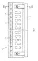
- the load securing bar 10 is shown in a plan view from the front.
- the front of the load securing bar 10 has a series of longitudinally spaced openings 11 at regular intervals in which cargo securing means such as straps or the like can be secured.
- the basic form of the load securing beam 10 is formed by two interconnected sub-profiles 12,13. Other attachments, such as an operating unit 14 in the form of a hand lever for moving the load securing bar 10 are provided in addition.
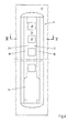
- Fig. 3 the back of the load securing bar 10 is shown.
- locking elements 16 are provided to set the load-securing bar 10 in the desired height in the double-decker rails 8. The locking elements 16 can be adjusted via the operating unit 14, and so release the load securing bar 10 for moving in the longitudinal direction of the double-decker rails 8.
- Fig. 4 and 5 are shown corresponding to the sliders 15 and the locking elements 16 formed double-decker rails 8.
- the double-deck rails 8 have a T-slot 17, which has a corresponding T-shaped cross-section. This shape of the groove 17 is provided by two ribs 18 which narrow the groove in the region of the opening 19 facing the loading space.
- the sliders 15 of the load securing beam 10 have a corresponding T-shaped cross-section, with which the slides 15 are received in the T-slots 17 of the double-decker rails 8.
- the sliders 15 can be moved along the double-deck rails 8, without the risk that the load-securing bar 10 is disengaged from the double-deck rails 8, because the sliders 15 engage behind during the sliding along the double-decker rail 8, the undercuts or ribs 18 of T-slot 17 of the double-deck rails 8. An accidental pulling out of the load securing beam 10 or sliding member 15 perpendicular to the side wall 5,6 is thus prevented.
- the double-decker rails 8 have along the groove bottom 20 recesses 21, in which the locking elements 16 of the load securing bar 10 can engage.
- the load securing bar 10 is then supported in its corresponding mounting position in the direction of gravity via the locking elements 16 and recesses 21 on the double-decker rails 8.
- the recesses 21 are arranged at constant distances from each other, so that a constant height grid is created.
- insertion openings 22 For insertion of the load securing bar 10, in the double-decker rails 8, these have at their lower ends insertion openings 22. These are essentially formed by shortened in this area ribs 18 of the T-groove 17.
- the sliders 15 of the load securing beam 10 can be inserted and then moved along the double-deck rails 8 upwards in the respective desired position.
- the sliders 15 can also be taken out of the double-decker rails 8 via the insertion openings 22, in particular pulled out, since the insertion openings 22 are wider than the parts of the sliders 15 to be inserted into the T-slot 17 in the same direction.
- the load securing bar 10 is shown in a side view.
- the operating unit 14 is arranged for adjusting the locking element 16.
- the illustrated in the extent preferred load securing bar 10 pin-shaped locking member 16 is in the illustrated mounting position against the sliding member 15 backwards.
- the Schiebling 15 in turn is facing the base body 23 to the rear, because the slide 15 engages in the T-groove 17 of the double-decker rail 8, while the locking member 16 engages in the mounting position also in the recesses 21 in the groove bottom 20 of the double-decker rails 8.
- the sliding members 15 engage behind the ribs 18 of the T-slots 17 with protrusions 24 projecting outward on both sides.
- the sliders 15 and the double-deck rails 8 are also coordinated so that the sliders 15 can be moved without great friction in the double-decker rails 8. So that this displacement does not lead to damage of the side wall 5,6 and / or the double-decker rails 8 is provided at the back of the body 23 of the load securing bar 10 top and bottom depending on a rearwardly projecting, bead-shaped scuff guard 25 which in the connected state on the side wall 5.6 and / or the double-decker rails 8 is present.
- Fig. 7 is a sectional view of the load securing bar 10 shown in the assembled position, while in the Fig. 8 the load securing bar 10 is shown in a positioning position.
- the basic form of the load securing bar 10 is composed of two partial profiles 12,13.
- the locking element 16 In the assembled position, the locking element 16 is displaced into a rear end position and is located on a stop 26 of the slide, against which the locking element 16 is pressed by the restoring force of a, in this case, the locking element 16 embracing spring 27 at.
- the locking member 16 also passes through the control unit 14, which is a Rotary axis 28 can be pivoted forward.
- the operating unit 14 presses a stop 29 of the locking member 16 forward and pushes the locking member 16 against the restoring force of the spring 27 and perpendicular to the double-decker rail 8 forward, and to the extent that the locking member 16 disengages from the recess 21 of the double-decker rail 8 ,
- the load securing bar 10 can therefore be easily moved up and down in the double-decker rails 8.
- the operator simply releases the control unit 14. Due to the restoring force of the spring 27, the load securing bar 10 or the locking element 16 returns to the assembly position. In this is given by the engagement of the locking elements in recesses 21 of the double-decker rails 8, a locking of the load securing bar 10 in the double-decker rails 8.
Landscapes
- Engineering & Computer Science (AREA)
- Transportation (AREA)
- Mechanical Engineering (AREA)
- Vehicle Step Arrangements And Article Storage (AREA)
- Conveying And Assembling Of Building Elements In Situ (AREA)
- Vehicle Cleaning, Maintenance, Repair, Refitting, And Outriggers (AREA)
Applications Claiming Priority (1)
| Application Number | Priority Date | Filing Date | Title |
|---|---|---|---|
| DE102012107910.2A DE102012107910A1 (de) | 2012-08-28 | 2012-08-28 | Nutzfahrzeugaufbau mit Ladungssicherung für den Doppelstockbetrieb |
Publications (3)
| Publication Number | Publication Date |
|---|---|
| EP2703216A2 true EP2703216A2 (fr) | 2014-03-05 |
| EP2703216A3 EP2703216A3 (fr) | 2015-10-07 |
| EP2703216B1 EP2703216B1 (fr) | 2019-10-02 |
Family
ID=49028926
Family Applications (1)
| Application Number | Title | Priority Date | Filing Date |
|---|---|---|---|
| EP13181124.2A Active EP2703216B1 (fr) | 2012-08-28 | 2013-08-21 | Structure de véhicule utilitaire avec sécurisation de charge pour le fonctionnement à deux niveaux |
Country Status (2)
| Country | Link |
|---|---|
| EP (1) | EP2703216B1 (fr) |
| DE (1) | DE102012107910A1 (fr) |
Cited By (1)
| Publication number | Priority date | Publication date | Assignee | Title |
|---|---|---|---|---|
| EP4173933A1 (fr) * | 2021-10-29 | 2023-05-03 | Kögel Trailer GmbH | Dispositif de retenue, panneau isolant doté d'un dispositif de retenue, carrosserie de véhicule, en particulier structure de véhicule de refroidissement, utilisation d'un tel dispositif de retenue |
Families Citing this family (3)
| Publication number | Priority date | Publication date | Assignee | Title |
|---|---|---|---|---|
| DE202015102860U1 (de) | 2015-06-02 | 2015-06-25 | Kiesling Fahrzeugbau Gmbh | Ladungssicherungssystem für einen Ladungsaufbau eines Nutzfahrzeugs |
| DE102015108731B4 (de) | 2015-06-02 | 2023-06-07 | Kiesling Fahrzeugbau Gmbh | Ladungssicherungssystem für einen Ladungsaufbau eines Nutzfahrzeugs |
| GB2595566A (en) * | 2021-04-08 | 2021-12-01 | Loadlok Mfg Limited | Low noise decking system |
Citations (2)
| Publication number | Priority date | Publication date | Assignee | Title |
|---|---|---|---|---|
| EP2116448A1 (fr) | 2008-05-09 | 2009-11-11 | Schmitz Cargobull AG | Panneau pour une construction de coffre doté d'un rail de fixation de dispositifs supplémentaires |
| DE102008015757B3 (de) | 2008-03-26 | 2009-12-31 | Sommer Road Cargo Solutions Gmbh & Co. Kg | Variabler Wechselkoffer |
Family Cites Families (5)
| Publication number | Priority date | Publication date | Assignee | Title |
|---|---|---|---|---|
| DE19533784A1 (de) * | 1995-09-13 | 1997-03-20 | Peter Schmitz | Lastfahrzeug mit übereinanderliegenden Ladeflächen |
| DE29801555U1 (de) * | 1998-02-03 | 1998-03-19 | Load-Lok Deutschland GmbH, 48619 Heek | Aufbau für ein Transportfahrzeug |
| DE20217747U1 (de) * | 2002-08-15 | 2003-02-20 | ANCRA Jungfalk GmbH & Co. KG, 78234 Engen | Vorrichtung zum Sichern von Ladegut auf der Ladefläche eines Fahrzeuges |
| US7731462B2 (en) * | 2007-07-12 | 2010-06-08 | Jps Corporation | Bulkhead for dividing a cargo container into two compartments |
| DE502008002664D1 (de) * | 2008-05-09 | 2011-04-07 | Schmitz Cargobull Ag | Paneel mit zwei Grundschienen für einen Kofferaufbau |
-
2012
- 2012-08-28 DE DE102012107910.2A patent/DE102012107910A1/de not_active Ceased
-
2013
- 2013-08-21 EP EP13181124.2A patent/EP2703216B1/fr active Active
Patent Citations (2)
| Publication number | Priority date | Publication date | Assignee | Title |
|---|---|---|---|---|
| DE102008015757B3 (de) | 2008-03-26 | 2009-12-31 | Sommer Road Cargo Solutions Gmbh & Co. Kg | Variabler Wechselkoffer |
| EP2116448A1 (fr) | 2008-05-09 | 2009-11-11 | Schmitz Cargobull AG | Panneau pour une construction de coffre doté d'un rail de fixation de dispositifs supplémentaires |
Cited By (1)
| Publication number | Priority date | Publication date | Assignee | Title |
|---|---|---|---|---|
| EP4173933A1 (fr) * | 2021-10-29 | 2023-05-03 | Kögel Trailer GmbH | Dispositif de retenue, panneau isolant doté d'un dispositif de retenue, carrosserie de véhicule, en particulier structure de véhicule de refroidissement, utilisation d'un tel dispositif de retenue |
Also Published As
| Publication number | Publication date |
|---|---|
| DE102012107910A1 (de) | 2014-03-06 |
| EP2703216A3 (fr) | 2015-10-07 |
| EP2703216B1 (fr) | 2019-10-02 |
Similar Documents
| Publication | Publication Date | Title |
|---|---|---|
| EP2835282B1 (fr) | Châssis de véhicule utilitaire avec installation de sécurisation de chargement déplaçable | |
| EP2703216B1 (fr) | Structure de véhicule utilitaire avec sécurisation de charge pour le fonctionnement à deux niveaux | |
| DE202015106050U1 (de) | Entfernbare Rahmensysteme für den Fahrzeugtransport | |
| DE102012001503B4 (de) | Palette zum Transportieren von Rollwagen | |
| EP2687404B1 (fr) | Agencement de sécurisation de chargement | |
| EP3293027B1 (fr) | Toit d'une structure bachee comprenant une structure de longeron | |
| EP3705330B1 (fr) | Structure de bâche pourvue de dispositif d'arrêt de montant coulissant | |
| EP1415854B2 (fr) | Dispositif d'immobilisation de charge | |
| EP2886393B1 (fr) | Sécurisation de charge pour une structure d'un véhicule utilitaire | |
| DE10312638A1 (de) | Verfahren und Vorrichtung zur Ladungssicherung | |
| DE60022604T2 (de) | System zur Befestigung von Gegenständen im Inneren eines Kraftfahrzeugs sowie gleitende Ankerelemente hierfür | |
| DE102008044503B3 (de) | Ladungs- und Sicherungssystem für Fahrzeuge | |
| EP1462346B1 (fr) | Système de ranchers pour véhicule ferroviaire. | |
| DE19706493A1 (de) | LKW-Aufbau | |
| WO2013131537A1 (fr) | Système de transport pour palettes pour le transport de marchandises | |
| DE1945636A1 (de) | Ladegutbehaelter mit senkrecht verstellbaren Ladedecks | |
| DE102017008892C5 (de) | Stapelsicherung für Transportkarren | |
| DE102016115786B4 (de) | Ladungssicherungseinrichtung für Nutzfahrzeuge | |
| EP1479562A2 (fr) | Véhicule pour le transport de marchandises et dispositif pour la fixation de la charge | |
| DE202008012966U1 (de) | Aufbau für ein Transportfahrzeug und mit einem solchen Aufbau versehener Sattelzug | |
| DE202018105152U1 (de) | Gabelstaplertasche und Verbindungsanordnung für eine Gabelstaplertasche an einem zu tragenden Gegenstand | |
| DE10303058B4 (de) | Runge mit integrierter Vorrichtung zur Ladungssicherung, insbesondere für Transportfahrzeuge mit Planenaufbauten | |
| EP1839942A2 (fr) | Arrière de camion avec rampe de chargement | |
| DE102017120200B4 (de) | Traggerüst für einen Planenaufbau eines Nutzfahrzeugs | |
| DE102010045430B4 (de) | Wechselaufbau für ein Nutzfahrzeug |
Legal Events
| Date | Code | Title | Description |
|---|---|---|---|
| AK | Designated contracting states |
Kind code of ref document: A2 Designated state(s): AL AT BE BG CH CY CZ DE DK EE ES FI FR GB GR HR HU IE IS IT LI LT LU LV MC MK MT NL NO PL PT RO RS SE SI SK SM TR |
|
| AX | Request for extension of the european patent |
Extension state: BA ME |
|
| PUAI | Public reference made under article 153(3) epc to a published international application that has entered the european phase |
Free format text: ORIGINAL CODE: 0009012 |
|
| PUAL | Search report despatched |
Free format text: ORIGINAL CODE: 0009013 |
|
| AK | Designated contracting states |
Kind code of ref document: A3 Designated state(s): AL AT BE BG CH CY CZ DE DK EE ES FI FR GB GR HR HU IE IS IT LI LT LU LV MC MK MT NL NO PL PT RO RS SE SI SK SM TR |
|
| AX | Request for extension of the european patent |
Extension state: BA ME |
|
| RIC1 | Information provided on ipc code assigned before grant |
Ipc: B60P 7/15 20060101AFI20150831BHEP |
|
| 17P | Request for examination filed |
Effective date: 20160322 |
|
| RBV | Designated contracting states (corrected) |
Designated state(s): AL AT BE BG CH CY CZ DE DK EE ES FI FR GB GR HR HU IE IS IT LI LT LU LV MC MK MT NL NO PL PT RO RS SE SI SK SM TR |
|
| GRAP | Despatch of communication of intention to grant a patent |
Free format text: ORIGINAL CODE: EPIDOSNIGR1 |
|
| STAA | Information on the status of an ep patent application or granted ep patent |
Free format text: STATUS: GRANT OF PATENT IS INTENDED |
|
| INTG | Intention to grant announced |
Effective date: 20190228 |
|
| GRAJ | Information related to disapproval of communication of intention to grant by the applicant or resumption of examination proceedings by the epo deleted |
Free format text: ORIGINAL CODE: EPIDOSDIGR1 |
|
| STAA | Information on the status of an ep patent application or granted ep patent |
Free format text: STATUS: REQUEST FOR EXAMINATION WAS MADE |
|
| GRAP | Despatch of communication of intention to grant a patent |
Free format text: ORIGINAL CODE: EPIDOSNIGR1 |
|
| STAA | Information on the status of an ep patent application or granted ep patent |
Free format text: STATUS: GRANT OF PATENT IS INTENDED |
|
| INTC | Intention to grant announced (deleted) | ||
| INTG | Intention to grant announced |
Effective date: 20190409 |
|
| GRAS | Grant fee paid |
Free format text: ORIGINAL CODE: EPIDOSNIGR3 |
|
| GRAA | (expected) grant |
Free format text: ORIGINAL CODE: 0009210 |
|
| STAA | Information on the status of an ep patent application or granted ep patent |
Free format text: STATUS: THE PATENT HAS BEEN GRANTED |
|
| AK | Designated contracting states |
Kind code of ref document: B1 Designated state(s): AL AT BE BG CH CY CZ DE DK EE ES FI FR GB GR HR HU IE IS IT LI LT LU LV MC MK MT NL NO PL PT RO RS SE SI SK SM TR |
|
| REG | Reference to a national code |
Ref country code: GB Ref legal event code: FG4D Free format text: NOT ENGLISH |
|
| REG | Reference to a national code |
Ref country code: CH Ref legal event code: EP Ref country code: AT Ref legal event code: REF Ref document number: 1185824 Country of ref document: AT Kind code of ref document: T Effective date: 20191015 |
|
| REG | Reference to a national code |
Ref country code: DE Ref legal event code: R096 Ref document number: 502013013678 Country of ref document: DE |
|
| REG | Reference to a national code |
Ref country code: IE Ref legal event code: FG4D Free format text: LANGUAGE OF EP DOCUMENT: GERMAN |
|
| REG | Reference to a national code |
Ref country code: NL Ref legal event code: MP Effective date: 20191002 |
|
| REG | Reference to a national code |
Ref country code: LT Ref legal event code: MG4D |
|
| PG25 | Lapsed in a contracting state [announced via postgrant information from national office to epo] |
Ref country code: ES Free format text: LAPSE BECAUSE OF FAILURE TO SUBMIT A TRANSLATION OF THE DESCRIPTION OR TO PAY THE FEE WITHIN THE PRESCRIBED TIME-LIMIT Effective date: 20191002 Ref country code: NL Free format text: LAPSE BECAUSE OF FAILURE TO SUBMIT A TRANSLATION OF THE DESCRIPTION OR TO PAY THE FEE WITHIN THE PRESCRIBED TIME-LIMIT Effective date: 20191002 Ref country code: NO Free format text: LAPSE BECAUSE OF FAILURE TO SUBMIT A TRANSLATION OF THE DESCRIPTION OR TO PAY THE FEE WITHIN THE PRESCRIBED TIME-LIMIT Effective date: 20200102 Ref country code: LT Free format text: LAPSE BECAUSE OF FAILURE TO SUBMIT A TRANSLATION OF THE DESCRIPTION OR TO PAY THE FEE WITHIN THE PRESCRIBED TIME-LIMIT Effective date: 20191002 Ref country code: PL Free format text: LAPSE BECAUSE OF FAILURE TO SUBMIT A TRANSLATION OF THE DESCRIPTION OR TO PAY THE FEE WITHIN THE PRESCRIBED TIME-LIMIT Effective date: 20191002 Ref country code: GR Free format text: LAPSE BECAUSE OF FAILURE TO SUBMIT A TRANSLATION OF THE DESCRIPTION OR TO PAY THE FEE WITHIN THE PRESCRIBED TIME-LIMIT Effective date: 20200103 Ref country code: LV Free format text: LAPSE BECAUSE OF FAILURE TO SUBMIT A TRANSLATION OF THE DESCRIPTION OR TO PAY THE FEE WITHIN THE PRESCRIBED TIME-LIMIT Effective date: 20191002 Ref country code: PT Free format text: LAPSE BECAUSE OF FAILURE TO SUBMIT A TRANSLATION OF THE DESCRIPTION OR TO PAY THE FEE WITHIN THE PRESCRIBED TIME-LIMIT Effective date: 20200203 Ref country code: SE Free format text: LAPSE BECAUSE OF FAILURE TO SUBMIT A TRANSLATION OF THE DESCRIPTION OR TO PAY THE FEE WITHIN THE PRESCRIBED TIME-LIMIT Effective date: 20191002 Ref country code: BG Free format text: LAPSE BECAUSE OF FAILURE TO SUBMIT A TRANSLATION OF THE DESCRIPTION OR TO PAY THE FEE WITHIN THE PRESCRIBED TIME-LIMIT Effective date: 20200102 Ref country code: FI Free format text: LAPSE BECAUSE OF FAILURE TO SUBMIT A TRANSLATION OF THE DESCRIPTION OR TO PAY THE FEE WITHIN THE PRESCRIBED TIME-LIMIT Effective date: 20191002 |
|
| PG25 | Lapsed in a contracting state [announced via postgrant information from national office to epo] |
Ref country code: RS Free format text: LAPSE BECAUSE OF FAILURE TO SUBMIT A TRANSLATION OF THE DESCRIPTION OR TO PAY THE FEE WITHIN THE PRESCRIBED TIME-LIMIT Effective date: 20191002 Ref country code: IS Free format text: LAPSE BECAUSE OF FAILURE TO SUBMIT A TRANSLATION OF THE DESCRIPTION OR TO PAY THE FEE WITHIN THE PRESCRIBED TIME-LIMIT Effective date: 20200224 Ref country code: HR Free format text: LAPSE BECAUSE OF FAILURE TO SUBMIT A TRANSLATION OF THE DESCRIPTION OR TO PAY THE FEE WITHIN THE PRESCRIBED TIME-LIMIT Effective date: 20191002 Ref country code: CZ Free format text: LAPSE BECAUSE OF FAILURE TO SUBMIT A TRANSLATION OF THE DESCRIPTION OR TO PAY THE FEE WITHIN THE PRESCRIBED TIME-LIMIT Effective date: 20191002 |
|
| PG25 | Lapsed in a contracting state [announced via postgrant information from national office to epo] |
Ref country code: AL Free format text: LAPSE BECAUSE OF FAILURE TO SUBMIT A TRANSLATION OF THE DESCRIPTION OR TO PAY THE FEE WITHIN THE PRESCRIBED TIME-LIMIT Effective date: 20191002 |
|
| REG | Reference to a national code |
Ref country code: DE Ref legal event code: R097 Ref document number: 502013013678 Country of ref document: DE |
|
| PG2D | Information on lapse in contracting state deleted |
Ref country code: IS |
|
| PG25 | Lapsed in a contracting state [announced via postgrant information from national office to epo] |
Ref country code: DK Free format text: LAPSE BECAUSE OF FAILURE TO SUBMIT A TRANSLATION OF THE DESCRIPTION OR TO PAY THE FEE WITHIN THE PRESCRIBED TIME-LIMIT Effective date: 20191002 Ref country code: RO Free format text: LAPSE BECAUSE OF FAILURE TO SUBMIT A TRANSLATION OF THE DESCRIPTION OR TO PAY THE FEE WITHIN THE PRESCRIBED TIME-LIMIT Effective date: 20191002 Ref country code: EE Free format text: LAPSE BECAUSE OF FAILURE TO SUBMIT A TRANSLATION OF THE DESCRIPTION OR TO PAY THE FEE WITHIN THE PRESCRIBED TIME-LIMIT Effective date: 20191002 Ref country code: IS Free format text: LAPSE BECAUSE OF FAILURE TO SUBMIT A TRANSLATION OF THE DESCRIPTION OR TO PAY THE FEE WITHIN THE PRESCRIBED TIME-LIMIT Effective date: 20200202 |
|
| PLBE | No opposition filed within time limit |
Free format text: ORIGINAL CODE: 0009261 |
|
| STAA | Information on the status of an ep patent application or granted ep patent |
Free format text: STATUS: NO OPPOSITION FILED WITHIN TIME LIMIT |
|
| PG25 | Lapsed in a contracting state [announced via postgrant information from national office to epo] |
Ref country code: SM Free format text: LAPSE BECAUSE OF FAILURE TO SUBMIT A TRANSLATION OF THE DESCRIPTION OR TO PAY THE FEE WITHIN THE PRESCRIBED TIME-LIMIT Effective date: 20191002 Ref country code: SK Free format text: LAPSE BECAUSE OF FAILURE TO SUBMIT A TRANSLATION OF THE DESCRIPTION OR TO PAY THE FEE WITHIN THE PRESCRIBED TIME-LIMIT Effective date: 20191002 Ref country code: IT Free format text: LAPSE BECAUSE OF FAILURE TO SUBMIT A TRANSLATION OF THE DESCRIPTION OR TO PAY THE FEE WITHIN THE PRESCRIBED TIME-LIMIT Effective date: 20191002 |
|
| 26N | No opposition filed |
Effective date: 20200703 |
|
| PG25 | Lapsed in a contracting state [announced via postgrant information from national office to epo] |
Ref country code: SI Free format text: LAPSE BECAUSE OF FAILURE TO SUBMIT A TRANSLATION OF THE DESCRIPTION OR TO PAY THE FEE WITHIN THE PRESCRIBED TIME-LIMIT Effective date: 20191002 |
|
| PG25 | Lapsed in a contracting state [announced via postgrant information from national office to epo] |
Ref country code: MC Free format text: LAPSE BECAUSE OF FAILURE TO SUBMIT A TRANSLATION OF THE DESCRIPTION OR TO PAY THE FEE WITHIN THE PRESCRIBED TIME-LIMIT Effective date: 20191002 |
|
| REG | Reference to a national code |
Ref country code: CH Ref legal event code: PL |
|
| GBPC | Gb: european patent ceased through non-payment of renewal fee |
Effective date: 20200821 |
|
| PG25 | Lapsed in a contracting state [announced via postgrant information from national office to epo] |
Ref country code: LU Free format text: LAPSE BECAUSE OF NON-PAYMENT OF DUE FEES Effective date: 20200821 Ref country code: LI Free format text: LAPSE BECAUSE OF NON-PAYMENT OF DUE FEES Effective date: 20200831 Ref country code: CH Free format text: LAPSE BECAUSE OF NON-PAYMENT OF DUE FEES Effective date: 20200831 |
|
| REG | Reference to a national code |
Ref country code: BE Ref legal event code: MM Effective date: 20200831 |
|
| PG25 | Lapsed in a contracting state [announced via postgrant information from national office to epo] |
Ref country code: BE Free format text: LAPSE BECAUSE OF NON-PAYMENT OF DUE FEES Effective date: 20200831 Ref country code: GB Free format text: LAPSE BECAUSE OF NON-PAYMENT OF DUE FEES Effective date: 20200821 Ref country code: IE Free format text: LAPSE BECAUSE OF NON-PAYMENT OF DUE FEES Effective date: 20200821 |
|
| REG | Reference to a national code |
Ref country code: AT Ref legal event code: MM01 Ref document number: 1185824 Country of ref document: AT Kind code of ref document: T Effective date: 20200821 |
|
| PG25 | Lapsed in a contracting state [announced via postgrant information from national office to epo] |
Ref country code: AT Free format text: LAPSE BECAUSE OF NON-PAYMENT OF DUE FEES Effective date: 20200821 |
|
| PG25 | Lapsed in a contracting state [announced via postgrant information from national office to epo] |
Ref country code: TR Free format text: LAPSE BECAUSE OF FAILURE TO SUBMIT A TRANSLATION OF THE DESCRIPTION OR TO PAY THE FEE WITHIN THE PRESCRIBED TIME-LIMIT Effective date: 20191002 Ref country code: MT Free format text: LAPSE BECAUSE OF FAILURE TO SUBMIT A TRANSLATION OF THE DESCRIPTION OR TO PAY THE FEE WITHIN THE PRESCRIBED TIME-LIMIT Effective date: 20191002 Ref country code: CY Free format text: LAPSE BECAUSE OF FAILURE TO SUBMIT A TRANSLATION OF THE DESCRIPTION OR TO PAY THE FEE WITHIN THE PRESCRIBED TIME-LIMIT Effective date: 20191002 |
|
| PG25 | Lapsed in a contracting state [announced via postgrant information from national office to epo] |
Ref country code: MK Free format text: LAPSE BECAUSE OF FAILURE TO SUBMIT A TRANSLATION OF THE DESCRIPTION OR TO PAY THE FEE WITHIN THE PRESCRIBED TIME-LIMIT Effective date: 20191002 |
|
| P01 | Opt-out of the competence of the unified patent court (upc) registered |
Effective date: 20230517 |
|
| PGFP | Annual fee paid to national office [announced via postgrant information from national office to epo] |
Ref country code: DE Payment date: 20250826 Year of fee payment: 13 |
|
| PGFP | Annual fee paid to national office [announced via postgrant information from national office to epo] |
Ref country code: FR Payment date: 20250826 Year of fee payment: 13 |