EP2703307B1 - Bouteille - Google Patents
Bouteille Download PDFInfo
- Publication number
- EP2703307B1 EP2703307B1 EP12775921.5A EP12775921A EP2703307B1 EP 2703307 B1 EP2703307 B1 EP 2703307B1 EP 12775921 A EP12775921 A EP 12775921A EP 2703307 B1 EP2703307 B1 EP 2703307B1
- Authority
- EP
- European Patent Office
- Prior art keywords
- wall portion
- bottle
- radial direction
- annular recess
- movable wall
- Prior art date
- Legal status (The legal status is an assumption and is not a legal conclusion. Google has not performed a legal analysis and makes no representation as to the accuracy of the status listed.)
- Active
Links
Images




Classifications
-
- B—PERFORMING OPERATIONS; TRANSPORTING
- B65—CONVEYING; PACKING; STORING; HANDLING THIN OR FILAMENTARY MATERIAL
- B65D—CONTAINERS FOR STORAGE OR TRANSPORT OF ARTICLES OR MATERIALS, e.g. BAGS, BARRELS, BOTTLES, BOXES, CANS, CARTONS, CRATES, DRUMS, JARS, TANKS, HOPPERS, FORWARDING CONTAINERS; ACCESSORIES, CLOSURES, OR FITTINGS THEREFOR; PACKAGING ELEMENTS; PACKAGES
- B65D1/00—Rigid or semi-rigid containers having bodies formed in one piece, e.g. by casting metallic material, by moulding plastics, by blowing vitreous material, by throwing ceramic material, by moulding pulped fibrous material or by deep-drawing operations performed on sheet material
- B65D1/02—Bottles or similar containers with necks or like restricted apertures, designed for pouring contents
- B65D1/0223—Bottles or similar containers with necks or like restricted apertures, designed for pouring contents characterised by shape
- B65D1/0261—Bottom construction
- B65D1/0284—Bottom construction having a discontinuous contact surface, e.g. discrete feet
-
- B—PERFORMING OPERATIONS; TRANSPORTING
- B65—CONVEYING; PACKING; STORING; HANDLING THIN OR FILAMENTARY MATERIAL
- B65D—CONTAINERS FOR STORAGE OR TRANSPORT OF ARTICLES OR MATERIALS, e.g. BAGS, BARRELS, BOTTLES, BOXES, CANS, CARTONS, CRATES, DRUMS, JARS, TANKS, HOPPERS, FORWARDING CONTAINERS; ACCESSORIES, CLOSURES, OR FITTINGS THEREFOR; PACKAGING ELEMENTS; PACKAGES
- B65D1/00—Rigid or semi-rigid containers having bodies formed in one piece, e.g. by casting metallic material, by moulding plastics, by blowing vitreous material, by throwing ceramic material, by moulding pulped fibrous material or by deep-drawing operations performed on sheet material
- B65D1/02—Bottles or similar containers with necks or like restricted apertures, designed for pouring contents
- B65D1/0223—Bottles or similar containers with necks or like restricted apertures, designed for pouring contents characterised by shape
- B65D1/0261—Bottom construction
- B65D1/0276—Bottom construction having a continuous contact surface, e.g. Champagne-type bottom
-
- B—PERFORMING OPERATIONS; TRANSPORTING
- B65—CONVEYING; PACKING; STORING; HANDLING THIN OR FILAMENTARY MATERIAL
- B65D—CONTAINERS FOR STORAGE OR TRANSPORT OF ARTICLES OR MATERIALS, e.g. BAGS, BARRELS, BOTTLES, BOXES, CANS, CARTONS, CRATES, DRUMS, JARS, TANKS, HOPPERS, FORWARDING CONTAINERS; ACCESSORIES, CLOSURES, OR FITTINGS THEREFOR; PACKAGING ELEMENTS; PACKAGES
- B65D1/00—Rigid or semi-rigid containers having bodies formed in one piece, e.g. by casting metallic material, by moulding plastics, by blowing vitreous material, by throwing ceramic material, by moulding pulped fibrous material or by deep-drawing operations performed on sheet material
- B65D1/02—Bottles or similar containers with necks or like restricted apertures, designed for pouring contents
-
- B—PERFORMING OPERATIONS; TRANSPORTING
- B29—WORKING OF PLASTICS; WORKING OF SUBSTANCES IN A PLASTIC STATE IN GENERAL
- B29C—SHAPING OR JOINING OF PLASTICS; SHAPING OF MATERIAL IN A PLASTIC STATE, NOT OTHERWISE PROVIDED FOR; AFTER-TREATMENT OF THE SHAPED PRODUCTS, e.g. REPAIRING
- B29C49/00—Blow-moulding, i.e. blowing a preform or parison to a desired shape within a mould; Apparatus therefor
- B29C49/42—Component parts, details or accessories; Auxiliary operations
- B29C49/48—Moulds
- B29C49/54—Moulds for undercut articles
- B29C49/541—Moulds for undercut articles having a recessed undersurface
-
- B—PERFORMING OPERATIONS; TRANSPORTING
- B65—CONVEYING; PACKING; STORING; HANDLING THIN OR FILAMENTARY MATERIAL
- B65D—CONTAINERS FOR STORAGE OR TRANSPORT OF ARTICLES OR MATERIALS, e.g. BAGS, BARRELS, BOTTLES, BOXES, CANS, CARTONS, CRATES, DRUMS, JARS, TANKS, HOPPERS, FORWARDING CONTAINERS; ACCESSORIES, CLOSURES, OR FITTINGS THEREFOR; PACKAGING ELEMENTS; PACKAGES
- B65D2501/00—Containers having bodies formed in one piece
- B65D2501/0009—Bottles or similar containers with necks or like restricted apertures designed for pouring contents
- B65D2501/0018—Ribs
- B65D2501/0036—Hollow circonferential ribs
Definitions
- the present invention relates to a bottle.
- the conventional bottle includes, for example, as described in the following Patent Document 1 ( PCT International Publication No. WO2010/061758 ), a ground portion having a bottom wall portion of a bottom portion disposed at an outer circumferential edge portion, a rising circumferential wall portion extending upward so as to be connected to the ground portion from the inside in a bottle radial direction, a movable wall portion protruding from an upper end portion of the rising circumferential wall portion toward the inside of the bottle radial direction, and a recessed circumferential wall portion extending upward from an inner end portion in the bottle radial direction of the movable wall portion.
- Patent Document 1 PCT International Publication No. WO2010/061758
- EP 0348147 discloses a bottomed cylindrical bottle according to the preamble of claim 1.
- the present invention proposes the following features.
- a bottle according to a first aspect of the present invention includes all the features of claim 1.
- the annular recess is formed at the movable wall portion, in a process of forming the bottle using a preform through biaxially oriented blow molding, when the material arrives at an area in the cavity inner surface in which the annular recess is formed, the force of the flow of the synthetic resin material is weakened.
- the synthetic resin material that forms an area in the movable wall portion disposed at the outside in the bottle radial direction farther than the annular recess (hereinafter referred to as an outer sidewall portion) can extend more than the synthetic resin material that forms an area in the recessed circumferential wall portion and the movable wall portion disposed closer to the inside in the bottle radial direction than the annular recess (hereinafter referred to as an inner sidewall portion).
- a thickness of the above-mentioned outer sidewall portion is formed to be thinner than that of the inner sidewall portion so that deformation can easily occur (the movable wall portion is easily displaced upward), and thus decompression absorption performance of the bottle can be improved.
- the movable wall portion may have a curved surface protruding downward.
- the movable wall portion upon the decompression in the bottle, the movable wall portion can be largely and easily deformed toward the inside of the bottle, and thus decompression absorption performance of the bottle can be more securely improved.
- the inner end portion connected to the inner end in the bottle radial direction of the annular recess in the movable wall portion may gradually extend upward in a direction from the inside toward the outside in the bottle radial direction
- the outer end portion connected to the outer end in the bottle radial direction of the annular recess in the movable wall portion may gradually extend downward in a direction from the inside toward the outside in the bottle radial direction
- the inner end portion connected to the inner end in the bottle radial direction of the annular recess in the movable wall portion may gradually extend upward in a direction from the inside toward the outside in the bottle radial direction
- the outer end portion connected to the outer end in the bottle radial direction of the annular recess in the movable wall portion may gradually extend downward in a direction from the inside toward the outside in the bottle radial direction
- the synthetic resin material can smoothly flow toward the outside in the bottle radial direction. Accordingly, the above-mentioned outer sidewall portion can be extended to reduce the thickness thereof.
- the movable wall portion may be disposed to be movable upward with the recessed circumferential wall portion around a connecting portion with the rising circumferential wall portion, and the inner portion disposed closer to the inside in the radial direction than the annular recess of the movable wall portion and the recessed circumferential wall portion may be disposed to be movable upward and around the annular recess.
- the decompression in the bottle since the area of the movable wall portion and the recessed circumferential wall portion disposed closer to the inside in the radial direction than the annular recess (hereinafter referred to as an inner portion) can be moved upward and the bottom wall portion can be actively deformed while moving the movable wall portion upward with the recessed circumferential wall portion around the connecting portion with the rising circumferential wall portion, decompression absorption performance of the bottle can be improved.
- the annular recess can be easily deformed to increase the size in the radial direction, and a sufficient upward movement amount of the recessed circumferential wall portion can be easily secured.
- a rib may be formed at the inner portion along with the circumferential direction, and the rib may be formed through biaxially oriented blow molding.
- an area of the movable wall portion and the recessed circumferential wall portion disposed between the rib and the annular recess (hereinafter referred to as an intermediate portion) can be formed to have a small thickness, and the intermediate portion can be easily deformed. Accordingly, the above-mentioned inner portion of the recessed circumferential wall portion can be more easily moved upward and around the annular recess, and thus the decompression absorption performance can be securely improved.
- a bottle 1 As shown in FIGS. 1 and 2 , a bottle 1 according to the embodiment includes a mouth portion 11, a shoulder portion 12, a drum portion 13, and a bottom portion 14.
- the bottle 1 has a schematic constitution in which the components 11 to 14 are installed in sequence in a state in which central axes of the components 11 to 14 are disposed on a common axis.
- a bottle axis O the mouth portion 11 side in the bottle axis O direction is referred to as an upper side
- the bottom portion 14 side is referred to as a lower side
- a direction perpendicular to the bottle axis O is referred to as a radial direction
- a direction around the bottle axis O is referred to as a circumferential direction.
- the bottle 1 has a constitution that a bottomed cylindrical preform formed through injection molding is integrally formed of a synthetic resin material through biaxially oriented blow molding.
- a cap (not shown) is mounted on the mouth portion 11. Further, the mouth portion 11, the shoulder portion 12, the drum portion 13, and the bottom portion 14 have a circular shape perpendicular to the bottle axis O in view of a lateral cross-sectional direction.
- the shoulder portion 12 has a curved surface having a diameter in the radial direction such that the diameter gradually increases in the direction from the upper side to the lower side and protruding outward in the radial direction.
- a reinforcement groove 16 is formed at a lower end portion of the shoulder portion 12 (a connecting portion between the shoulder portion 12 and the drum portion 13) throughout the entire circumference.
- the reinforcement groove 16 is a groove portion (a recessed rib) configured to increase the rigidity of the shoulder portion 12.
- the drum portion 13 is formed in a tubular shape, and a space between both of end portions in the bottle axis O direction has a smaller diameter than that of both of the end portions.
- a plurality of first annular recessed grooves 15 are continuously formed at the drum portion 13 in the bottle axis O direction at an interval throughout the entire circumference.
- a second annular recessed groove 20 is continuously formed at the connecting portion between the drum portion 13 and the bottom portion 14 throughout the entire circumference.
- the bottom portion 14 having a cup shape includes a heel portion 17 having an upper end opening mouth portion connected to a lower end opening mouth portion of the drum portion 13, and a bottom wall portion 19 configured to close a lower end opening mouth portion of the heel portion 17 and in which an outer circumferential edge portion becomes a ground portion 18.
- a third annular recessed groove 31 having the same depth as the second annular recessed groove 20 is continuously formed at the heel portion 17 throughout the entire circumference.
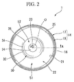
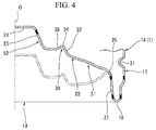
- the bottom wall portion 19 includes a rising circumferential wall portion 21 extending upward so as to be connected to the ground portion 18 from the inside of the bottle in the radial direction toward the upper side, an annular movable wall portion 22 protruding from the upper end portion of the rising circumferential wall portion 21 toward the inside of the bottle in the radial direction, an annular recessed circumferential wall portion 23 having a diameter in the radial direction such that the diameter gradually decreases with directed to upward from the inner end portion of the movable wall portion 22, and a closing wall portion 24 configured to close the upper end opening mouth portion of the recessed circumferential wall portion 23.
- the movable wall portion 22 has a curved surface protruding downward.
- the movable wall portion 22 and the rising circumferential wall portion 21 are connected via a curved surface portion 25 protruding upward. Then, the movable wall portion 22 is pivotable about the curved surface portion 25 such that the recessed circumferential wall portion 23 is moved upward.
- the recessed circumferential wall portion 23 is disposed concentrically with the bottle axis O, and continuously installed at the inner end portion in the radial direction of the movable wall portion 22. Accordingly, the recessed circumferential wall portion 23 has a diameter in the radial direction that gradually decreases in the direction from the lower side to the upper side.
- annular recess 30 recessed upward is continuously formed at an inner circumferential side in the movable wall portion 22 throughout the entire circumference in the circumferential direction.
- the annular recess 30 is divided into an apex portion 34, an outer curved wall (an outer end portion) 32 connected to the apex portion 34 from the outside in the radial direction, and an inner curved wall (an inner end portion) 35 connected to the apex portion 34 from the inside in the radial direction.
- the outer curved wall 32 has a curved surface that gradually extends downward in the direction from the inside to the outside in the radial direction and protrudes (swells) downward. Then, the upper end portion of the outer curved wall 32 is connected to the outer end portion in the radial direction of the apex portion 34.
- an inner curved wall 35 has a curved surface that gradually extends upward in the direction from the inside to the outside in the radial direction and protrudes downward. Then, the upper end portion of the inner curved wall 35 is connected to the inner end portion in the radial direction of the apex portion 34.
- the apex portion 34 of the annular recess 30 has a curved surface protruding upward. That is, the annular recess 30 has a curved surface recessed to have a size in the radial direction that gradually decreases overall in the direction from the lower side to the upper side, and the apex portion 34 disposed at an upper end thereof protrudes upward.
- the radii of curvature of the above-mentioned apex portion 34, the movable wall portion 22, and the curved surface portion 25 are formed so that the radii of curvature of the movable wall portion 22 is smaller than the radii of curvature of the curved surface portion 25, and the radii of curvature of the curved surface portion 25 is smaller than the radii of curvature of the apex portion 34.
- the apex portion 34 of the annular recess 30 is disposed under the upper end portion of the above-mentioned curved surface portion 25 and over the inner curved wall 35.
- the annular recess 30 is disposed over an imaginary line L extending along with a surface shape of the outer end portion in the radial direction of the outer curved wall 32 and the inner end portion in the radial direction of the inner curved wall 35 (a connecting portion with the recessed circumferential wall portion 23).
- the outer curved wall 32 and the inner curved wall 35 are also disposed over the imaginary line L.
- a length D1 in the radial direction from the curved surface portion 25 to the apex portion 34 of the annular recess 30 is larger than a length D2 in the radial direction from the apex portion 34 to the outer circumferential edge of the closing wall portion 24.
- a thickness of a portion in the movable wall portion 22 disposed further outside in the radial direction than the apex portion 34 of the annular recess 30, specifically, a portion disposed further outside in the radial direction than the outer curved wall 32 and the inner curved wall 35 is thinner than those of the inner curved wall 35 of the recessed circumferential wall portion 23 and the movable wall portion 22 (hereinafter, collectively referred to as an inner sidewall portion 52).
- a bottomed cylindrical preform formed of a synthetic resin material is manufactured through injection molding. Then, after the preform is set in a cavity, air is blown into the preform to perform blow forming. Accordingly, as the preform is extended and expanded in both the bottle axis O direction and the radial direction, the bottomed cylindrical bottle 1 following the inner surface of the cavity is molded.
- the annular recess 30 is formed at the movable wall portion 22, in a process of forming the bottle 1 through the biaxially oriented blow molding using the preform, a force of the flow of the synthetic resin material is weakened when the material arrives at an area in the cavity inner surface at which the annular recess 30 (the apex portion 34) is formed. Accordingly, in comparison with the synthetic resin material that forms the inner sidewall portion 52, the synthetic resin material that forms the above-mentioned outer sidewall portion 51 can be further extended. Accordingly, the thickness of the outer sidewall portion 51 is formed to be thinner than that of the inner sidewall portion 52.
- the outer sidewall portion 51 can be easily moved (pivoted) around the upper end portion of the rising circumferential wall portion 21. For this reason, the outer sidewall portion 51 can be flexibly deformed according to the internal pressure variation of the bottle 1.
- the thickness of the outer sidewall portion 51 can be formed to be thinner than that of the inner sidewall portion 52. Accordingly, the outer sidewall portion 51 in the bottom wall portion 19 can be easily deformed, and thus decompression absorption performance of the bottle 1 can be improved.
- the inner curved wall 35 gradually extends upward in the direction from the inside to the outside in the radial direction. Accordingly, in the process of forming the bottle 1 as described above, the force of the flow of the synthetic resin material can be effectively weakened when the material arrives at an area in the cavity inner surface in which the apex portion 34 of the annular recess 30 is formed.
- the outer curved wall 32 gradually extends downward in the direction from the inside to the outside in the radial direction. Accordingly, in the process of forming the bottle 1 as described above, after passing through the area in the cavity inner surface in which the apex portion 34 of the annular recess 30 is formed, the synthetic resin material toward the outside in the radial direction can smoothly flow. Accordingly, the above-mentioned outer sidewall portion 51 can extend to effectively reduce the thickness thereof.
- the movable wall portion 22 has a curved surface protruding downward, upon the decompression in the bottle 1, the movable wall portion 22 can be largely and easily deformed toward the inside of the bottle 1. As a result, the decompression absorption performance of the bottle 1 can be more securely improved.
- the embodiment is not limited thereto.
- the annular recess 30 may be intermittently formed or continuously extend throughout the entire circumference in the circumferential direction.
- the plurality of annular recesses 30 may be formed in the radial direction at an interval.
- a cross-sectional shape of the annular recess 30 may be appropriately design-changed into a circular shape, a rectangular shape, or the like. Furthermore, the size of the annular recess 30 may be varied.
- a bottle 100 As shown in FIGS. 5 to 7 , a bottle 100 according to the embodiment includes a mouth portion 111, a shoulder portion 112, a drum portion 113, and a bottom portion 114.
- the bottle 100 has a schematic constitution in which the components 111 to 114 are continuously installed in sequence in a state in which central axes of the components 111 to 114 are disposed on a common axis.
- the above-mentioned common axis is referred to as a bottle axis O
- the mouth portion 111 side in the bottle axis O direction is referred to as an upper side
- the bottom portion 114 side is referred to as a lower side
- a direction perpendicular to the bottle axis O is referred to as a radial direction
- a direction around the bottle axis O is referred to as a circumferential direction.
- the bottle 100 has a constitution that a bottomed cylindrical preform formed through injection molding is integrally formed of a synthetic resin material through biaxially oriented blow molding.
- a cap (not shown) is mounted on the mouth portion 111.
- the mouth portion 111, the shoulder portion 112, the drum portion 113, and the bottom portion 114 have a circular shape perpendicular to the bottle axis O in view of a lateral cross-sectional direction.
- the shoulder portion 112 has a curved surface having a diameter in the radial direction such that the diameter gradually increases in the direction from the upper side to the lower side and protrudes outward in the radial direction.
- a plurality of (for example, two) reinforcement grooves 116 are formed at the shoulder portion 112 in the bottle axis O direction at an interval throughout the entire circumference.
- the reinforcement grooves 116 are groove portions (recessed ribs) configured to increase the rigidity of the shoulder portion 112.
- the drum portion 113 is formed in a tubular shape, and a space between both of end portions in the bottle axis O direction has a smaller diameter than either of the end portions.
- a plurality of first annular recessed grooves 115 are continuously formed at the drum portion 113 in the bottle axis O direction at an interval throughout the entire circumference.
- a second annular recessed groove 120 is continuously formed at the connecting portion between the drum portion 113 and the bottom portion 114 throughout the entire circumference.
- the bottom portion 114 having a cup shape includes a heel portion 117 having an upper end opening mouth portion connected to a lower end opening mouth portion of the drum portion 113, and a bottom wall portion 119 configured to close a lower end opening mouth portion of the heel portion 117 and in which a bottom wall portion 119 becomes a ground portion 118.
- a third annular recessed groove 131 having the same depth as the second annular recessed groove 120 is continuously formed at the heel portion 117 throughout the entire circumference.
- an uneven portion 117a having a low protrusion height is formed at an outer circumferential surface of the heel portion 117 and an outer circumferential surface of a lower end portion of the drum portion 113 (see FIG. 5 ). Accordingly, in a filling process, when the plurality of bottles 100 are continuously stood and conveyed, close contacts and non-smooth sliding between the outer circumferential surfaces of the heel portions 117 of the neighboring bottles 100 and the outer circumferential surfaces of the lower end portions of the drum portions 113 are suppressed, i.e., generation of blocking is suppressed.
- an uneven portion 117a is also formed on a surface of the second annular recessed groove 120 and a surface of the third annular recessed groove 131.
- the bottom wall portion 119 includes a rising circumferential wall portion 121 continuously extending upward so as to be connected to the ground portion 118 from the inside in the radial direction, an outer movable wall portion 122 having a curved surface protruding downward, an annular curved portion 123 having a diameter in the radial direction such that the diameter gradually decreases in the direction from the inner end portion of the outer movable wall portion 122 to the upper side, and a closing wall portion 124 configured to close the upper end opening mouth portion of the curved portion 123.
- annular movable wall portion 127 protruding from the upper end portion of the rising circumferential wall portion 121 toward the inside in the radial direction is constituted by the outer movable wall portion 122, a lower tubular portion 123a and a connecting portion 123c of the curved portion 123, which will be described below.
- a plurality of protrusions 121a protruding toward the inside in the radial direction are formed at the rising circumferential wall portion 121 in the circumferential direction at an interval.
- the outer movable wall portion 122 gradually extends downward in the direction from the outside to the inside in the radial direction.
- the outer movable wall portion 122 and the rising circumferential wall portion 121 are connected via a curved surface portion 125 protruding upward.
- the outer movable wall portion 122 is pivotable about the curved surface portion 125 such that the curved portion 123 is moved upward.
- the movable wall portion 127 is disposed to be movable upward with a recessed circumferential wall portion 123b around a connecting portion with the rising circumferential wall portion 121.
- a plurality of ribs 126 are radially disposed at the outer movable wall portion 122 around the bottle axis O. That is, the respective ribs 126 are disposed in the circumferential direction at the same interval.
- the ribs 126 are formed by intermittently and straightly extending a plurality of recesses 126a recessed upward in a curved surface in the radial direction. Accordingly, the ribs 126 have a waved shape in the bottle axis O direction in a view of a longitudinal cross-sectional direction.
- the respective recesses 126a have the same shape and the same size, and are disposed in the radial direction at the same interval. Then, the plurality of ribs 126 are disposed at the same positions in the radial direction in which the plurality of recesses 126a are disposed. In each of the ribs 126, the recess 126a disposed at the outermost side in the radial direction in the plurality of recesses 126a approaches the curved surface portion 125 from the inside in the radial direction of the curved surface portion 125, and the recess 126a disposed at the innermost side in the radial direction approaches the curved portion 123 from the outside in the radial direction of the curved portion 123.
- the curved portion 123 includes the lower tubular portion 123a disposed concentrically with the bottle axis O, continuously installed at the inner end portion in the radial direction of the outer movable wall portion 122, and having a diameter in the radial direction such that the diameter gradually decreases in the direction from the lower side to the upper side, the recessed circumferential wall portion 123b continuously installed at an outer circumferential edge of the above-mentioned closing wall portion 124 and having a diameter in the radial direction such that the diameter gradually increases with directed to the lower side, and the connecting portion 123c configured to connect the lower tubular portion 123a and the recessed circumferential wall portion 123b.
- the connecting portion 123c has a curved surface protruding downward.
- annular rib 137 depressed upward in a curved surface is formed at an inner circumferential side of the connecting portion 123c (a connecting portion with the recessed circumferential wall portion 123b) throughout the entire circumference in the circumferential direction.
- annular recess 130 depressed upward is formed at the connecting portion to the lower tubular portion 123a and the connecting portion 123c, which are the movable wall portion 127 throughout the entire circumference in the circumferential direction.
- the lower tubular portion 123a has a curved surface protruding (swelling) downward.
- An apex wall 134 of the annular recess 130 has a curved surface protruding upward. That is, a depressed curved surface having a size in the radial direction that gradually decreases in the direction from the lower side to the upper side as a whole and having an upper end portion protruding upward is provided.
- the radii of curvature of the above-mentioned lower tubular portion 123 a and connecting portion 123c are formed to be smaller than that of the above-mentioned outer movable wall portion 122.
- an inner portion disposed closer to the inside in the radial direction than the annular recess 130 in the movable wall portion 127 and the recessed circumferential wall portion 123b is disposed to be movable upward and around the annular recess 130.
- the apex wall 134 of the annular recess 130 is disposed under the upper end portion of the above-mentioned curved surface portion 125 and over the connecting portion 123c.
- the annular recess 130 is disposed over the imaginary line L extending along with surface shapes of the outer end portion in the radial direction of the lower tubular portion 123 a (the connecting portion with the outer movable wall portion 122) and the inner end portion in the radial direction of the connecting portion 123c (the connecting portion with the recessed circumferential wall portion 123b).
- the connecting portion 123c is also disposed over the imaginary line L.
- the length D1 in the radial direction from the curved surface portion 125 to the apex wall 134 of the annular recess 130 is larger than the length D2 in the radial direction from the apex wall 134 to the outer circumferential edge of the closing wall portion 124.
- the movable wall portion 127 When the inside of the bottle 100 configured as described above is decompressed, first, as shown in FIG. 8 , the movable wall portion 127 upwardly pivots about the curved surface portion 125 of the bottom wall portion 119. Accordingly, the movable wall portion 127 is moved so as to raise the recessed circumferential wall portion 123b and the closing wall portion 124 upward. That is, as the bottom wall portion 119 of the bottle 100 is actively deformed upon the decompression, internal pressure variation (decompression) of the bottle 100 can be absorbed without deformation of the drum portion 113 or the like.
- the connecting portion between the rising circumferential wall portion 121 and the movable wall portion 127 is formed at the curved surface portion 125 protruding upward, the movable wall portion 127 can be easily moved (pivoted) around the upper end portion of the rising circumferential wall portion 121. For this reason, the movable wall portion 127 can be flexibly deformed according to the internal pressure variation of the bottle 100.
- the outer movable wall portion 122 can move the inner portion of the curved portion 123 upward while moving the curved portion 123 and the closing wall portion 124 upward and around the curved surface portion 125 according to the decompression in the bottle 100. That is, the bottom wall portion 119 can be raised inward in the bottle 1 in a multi-stage shape. Accordingly, since the bottom wall portion 119 can be actively deformed, the decompression absorption performance of the bottle 100 can be improved.
- the annular recess 130 can be easily deformed while increasing the size in the radial direction, and a sufficient upward movement amount of the curved portion 123 can be easily secured.
- the rib 137 is formed in the circumferential direction at the inner portion disposed closer to the inside in the radial direction than the annular recess 130 in the movable wall portion 127 and the recessed circumferential wall portion 123b.
- the rib 137 is formed at the connecting portion 123c to be depressed upward in a curved surface shape.
- annular recess 130 and the rib 137 are continuously formed throughout the entire circumference in the circumferential direction, they are not limited thereto but may be intermittently formed throughout the entire circumference in the circumferential direction.
- the plurality of annular recesses 130 and the plurality of ribs 137 may be formed in radial directions at intervals.
- cross-sectional shapes of the annular recess 130 and the rib 137 may be appropriately design-changed into a circular shape, a rectangular shape, or the like. Furthermore, the sizes of the annular recess 130 and the rib 137 may be varied.
- pivotal movement about the curved surface portion 125 and pivotal movement about the annular recess 130 upon the decompression of the bottle 100 are sequentially performed
- the embodiment is not limited thereto but the pivotal movement about the curved surface portion 125 and the pivotal movement about the annular recess 130 may be performed in a reversed sequence or both of the pivotal movements may be simultaneously performed.
- rising circumferential wall portion 121 may be appropriately modified, for example, may extend parallel to the bottle axis O direction or may extend to be inclined with respect to the bottle axis O.
- the movable wall portion 127 may be appropriately modified, for example, may protrude parallel to the radial direction, or the like.
- the uneven portion 117a may not be formed.
- the synthetic resin material that forms the bottles 1 and 100 may be appropriately changed with, for example, polyethylene terephthalate, polyethylene naphthalate, non-crystalline polyester, or the like, or a blend material thereof.
- the bottles 1 and 100 are not limited to a single layer structure but may have a stacked-layer structure having an intermediate layer.
- the intermediate layer for example, a layer formed of a resin material having gas barrier characteristics, a layer formed of a recycled material, a layer formed of a resin material having an oxygen absorption property, or the like, may be used.
- the drum portions 13 and 113 and the bottom portions 14 and 114 have circular shapes
- the shapes are not limited thereto but may be appropriately modified into polygonal shapes.
Landscapes
- Engineering & Computer Science (AREA)
- Mechanical Engineering (AREA)
- Ceramic Engineering (AREA)
- Manufacturing & Machinery (AREA)
- Containers Having Bodies Formed In One Piece (AREA)
Claims (6)
- Bouteille cylindrique à fond (1) formée avec un matériau en résine synthétique par le biais du moulage par extrusion-soufflage orienté de manière biaxiale, comprenant une partie de fond (14) ayant une partie de paroi de fond (19), dans laquelle la partie de paroi de fond comprend :une partie de base (18) disposée au niveau d'une partie de bord circonférentielle externe ;une partie de paroi circonférentielle montante (21) s'étendant de manière continue vers le haut afin d'être raccordée à la partie de base à partir d'un intérieur dans une direction radiale de la bouteille ;une partie de paroi mobile (22) faisant saillie d'une partie d'extrémité supérieure de la partie de paroi circonférentielle montante vers l'intérieur dans la direction radiale de la bouteille ;caractérisé en ce que ladite partie de paroi de fond comprend en outre :une partie de paroi circonférentielle évidée (23) ayant un diamètre dans la direction radiale de la bouteille de sorte que le diamètre diminue progressivement dans une direction allant d'une partie d'extrémité interne de la partie de paroi mobile vers son côté supérieur ;une partie de raccordement (25) entre la partie de paroi circonférentielle montante (21) et la partie de paroi mobile (22) ; etdans laquelle un évidement annulaire (30) enfoncé vers le haut est formé au niveau de la partie de paroi mobile dans sa direction circonférentielle, etune longueur D1 allant de la partie de raccordement (25) à l'évidement annulaire (30) dans la direction radiale de la bouteille est supérieure à une longueur D2 allant de l'évidement annulaire (30) à une partie de bord interne (24) de la partie de paroi circonférentielle évidée dans la direction radiale de la bouteille.
- Bouteille selon la revendication 1, dans laquelle la partie de paroi mobile (22) a une surface incurvée faisant saillie vers le bas.
- Bouteille selon la revendication 1, dans laquelle la partie d'extrémité interne raccordée à l'extrémité interne dans la direction radiale de la bouteille de l'évidement annulaire dans la partie de paroi mobile s'étend progressivement vers le haut dans une direction allant de l'intérieur vers l'extérieur dans la direction radiale de la bouteille, et la partie d'extrémité externe raccordée à l'extrémité externe dans la direction radiale de la bouteille de l'évidement annulaire dans la partie de paroi mobile s'étend progressivement vers le bas dans une direction allant de l'intérieur vers l'extérieur dans la direction radiale de la bouteille.
- Bouteille selon la revendication 2, dans laquelle la partie d'extrémité interne raccordée à l'extrémité interne dans la direction radiale de la bouteille de l'évidement annulaire dans la partie de paroi mobile s'étend progressivement vers le haut dans une direction allant de l'intérieur vers l'extérieur dans la direction radiale de la bouteille, et la partie d'extrémité externe raccordée à l'extrémité externe dans la direction radiale de la bouteille de l'évidement annulaire dans la partie de paroi mobile s'étend progressivement vers le bas dans une direction allant de l'intérieur vers l'extérieur dans la direction radiale de la bouteille.
- Bouteille selon la revendication 2, dans laquelle la partie de paroi mobile est disposée pour être mobile vers le haut avec la partie de paroi circonférentielle évidée autour de la partie de raccordement (25) avec la partie de paroi circonférentielle montante (21) et la partie interne disposées plus à proximité de l'intérieur dans la direction radiale que l'évidement annulaire (30) de la partie de paroi mobile et la partie de paroi circonférentielle évidée (23) est disposée pour être mobile vers le haut et autour de l'évidement annulaire.
- Bouteille selon la revendication 5, dans laquelle une nervure (137) est formée au niveau de la partie interne conjointement avec la direction circonférentielle, et la nervure est formée par le biais du moulage par extrusion-soufflage orienté de manière biaxiale.
Applications Claiming Priority (3)
| Application Number | Priority Date | Filing Date | Title |
|---|---|---|---|
| JP2011101984A JP5719677B2 (ja) | 2011-04-28 | 2011-04-28 | ボトル |
| JP2011285153A JP5826020B2 (ja) | 2011-12-27 | 2011-12-27 | ボトル |
| PCT/JP2012/061279 WO2012147885A1 (fr) | 2011-04-28 | 2012-04-26 | Bouteille |
Publications (3)
| Publication Number | Publication Date |
|---|---|
| EP2703307A1 EP2703307A1 (fr) | 2014-03-05 |
| EP2703307A4 EP2703307A4 (fr) | 2014-11-12 |
| EP2703307B1 true EP2703307B1 (fr) | 2016-02-10 |
Family
ID=47072400
Family Applications (1)
| Application Number | Title | Priority Date | Filing Date |
|---|---|---|---|
| EP12775921.5A Active EP2703307B1 (fr) | 2011-04-28 | 2012-04-26 | Bouteille |
Country Status (8)
| Country | Link |
|---|---|
| US (1) | US9617028B2 (fr) |
| EP (1) | EP2703307B1 (fr) |
| KR (1) | KR101877849B1 (fr) |
| CN (1) | CN103492274B (fr) |
| AU (1) | AU2012248279B2 (fr) |
| CA (1) | CA2834143C (fr) |
| TW (1) | TWI564219B (fr) |
| WO (1) | WO2012147885A1 (fr) |
Families Citing this family (8)
| Publication number | Priority date | Publication date | Assignee | Title |
|---|---|---|---|---|
| JP2015030466A (ja) | 2013-07-31 | 2015-02-16 | 株式会社吉野工業所 | 減圧吸収ボトル |
| DE102015003514A1 (de) | 2015-03-20 | 2016-09-22 | Khs Corpoplast Gmbh | Behälter und Blasform |
| JP7278971B2 (ja) * | 2018-01-18 | 2023-05-22 | 日精エー・エス・ビー機械株式会社 | 容器 |
| MX2020011255A (es) * | 2018-04-26 | 2020-11-12 | Graham Packaging Co | Recipiente de relleno presurizado resistente al agrietamiento del anillo de pie. |
| JP7370248B2 (ja) * | 2019-12-27 | 2023-10-27 | 株式会社吉野工業所 | ボトル |
| AU2021202920A1 (en) * | 2020-05-08 | 2021-11-25 | Orora Packaging Australia Pty Ltd | A bottle, and an insert and a mould for making the bottle |
| WO2021261578A1 (fr) | 2020-06-26 | 2021-12-30 | 株式会社吉野工業所 | Bouteille d'absorption de décompression |
| EP4543658A4 (fr) * | 2022-06-21 | 2026-04-22 | Amcor Rigid Packaging Usa Llc | Base de récipient moulée par soufflage, absorbant le vide |
Family Cites Families (12)
| Publication number | Priority date | Publication date | Assignee | Title |
|---|---|---|---|---|
| EP0348147A3 (fr) * | 1988-06-24 | 1990-10-24 | Hoover Universal Inc | Récipient en polyester pour liquides à remplissage chaud |
| JPH06336240A (ja) * | 1993-05-24 | 1994-12-06 | Mitsubishi Plastics Ind Ltd | 耐圧プラスチックボトル |
| JPH1149130A (ja) * | 1997-08-04 | 1999-02-23 | Mitsui Chem Inc | プラスチックボトルの底部構造 |
| JP2000281033A (ja) * | 1999-03-31 | 2000-10-10 | Yoshino Kogyosho Co Ltd | プラスチック容器 |
| US8276774B2 (en) * | 2003-05-23 | 2012-10-02 | Amcor Limited | Container base structure responsive to vacuum related forces |
| JP4725889B2 (ja) | 2006-03-31 | 2011-07-13 | 株式会社吉野工業所 | 合成樹脂製壜体 |
| JP2007290772A (ja) | 2006-04-27 | 2007-11-08 | Hokkai Can Co Ltd | 合成樹脂製ボトル及び合成樹脂製ボトルの製造方法 |
| JP5019810B2 (ja) * | 2006-07-18 | 2012-09-05 | 北海製罐株式会社 | 合成樹脂製ボトル及びその製造方法 |
| US8607999B2 (en) * | 2008-06-30 | 2013-12-17 | Yoshino Kogyosho Co., Ltd. | Laminated synthetic resin bottle, injection molding device, and process for molding a laminated preform |
| AU2009320858B2 (en) * | 2008-11-27 | 2013-12-19 | Yoshino Kogyosho Co., Ltd. | Synthetic resin bottle |
| FR2941924B1 (fr) * | 2009-02-12 | 2011-05-13 | Sidel Participations | Recipient dont le fond est muni d'une voute flexible a double assise |
| PE20121189A1 (es) * | 2009-07-31 | 2012-09-06 | Amcor Ltd | Recipiente de llenado en caliente |
-
2012
- 2012-04-26 CN CN201280020226.7A patent/CN103492274B/zh not_active Expired - Fee Related
- 2012-04-26 EP EP12775921.5A patent/EP2703307B1/fr active Active
- 2012-04-26 WO PCT/JP2012/061279 patent/WO2012147885A1/fr not_active Ceased
- 2012-04-26 CA CA2834143A patent/CA2834143C/fr active Active
- 2012-04-26 AU AU2012248279A patent/AU2012248279B2/en not_active Ceased
- 2012-04-26 US US14/113,078 patent/US9617028B2/en active Active
- 2012-04-26 KR KR1020137027436A patent/KR101877849B1/ko not_active Expired - Fee Related
- 2012-04-27 TW TW101115278A patent/TWI564219B/zh active
Also Published As
| Publication number | Publication date |
|---|---|
| EP2703307A1 (fr) | 2014-03-05 |
| CN103492274A (zh) | 2014-01-01 |
| CA2834143C (fr) | 2019-01-08 |
| AU2012248279A1 (en) | 2013-11-07 |
| KR101877849B1 (ko) | 2018-07-12 |
| CA2834143A1 (fr) | 2012-11-01 |
| US9617028B2 (en) | 2017-04-11 |
| KR20140125284A (ko) | 2014-10-28 |
| US20140034659A1 (en) | 2014-02-06 |
| EP2703307A4 (fr) | 2014-11-12 |
| WO2012147885A1 (fr) | 2012-11-01 |
| AU2012248279B2 (en) | 2016-08-25 |
| TWI564219B (zh) | 2017-01-01 |
| CN103492274B (zh) | 2015-03-11 |
| TW201302552A (zh) | 2013-01-16 |
Similar Documents
| Publication | Publication Date | Title |
|---|---|---|
| EP2703307B1 (fr) | Bouteille | |
| KR101818078B1 (ko) | 병 | |
| EP2623426B1 (fr) | Bouteille | |
| JP5719677B2 (ja) | ボトル | |
| US9555927B2 (en) | Bottle | |
| JP5826020B2 (ja) | ボトル | |
| JP6224300B2 (ja) | ボトル | |
| JP5684534B2 (ja) | ボトル | |
| JP6335736B2 (ja) | ボトル | |
| JP5568439B2 (ja) | ボトル | |
| JP5902385B2 (ja) | ボトルの製造方法 |
Legal Events
| Date | Code | Title | Description |
|---|---|---|---|
| PUAI | Public reference made under article 153(3) epc to a published international application that has entered the european phase |
Free format text: ORIGINAL CODE: 0009012 |
|
| 17P | Request for examination filed |
Effective date: 20131030 |
|
| AK | Designated contracting states |
Kind code of ref document: A1 Designated state(s): AL AT BE BG CH CY CZ DE DK EE ES FI FR GB GR HR HU IE IS IT LI LT LU LV MC MK MT NL NO PL PT RO RS SE SI SK SM TR |
|
| DAX | Request for extension of the european patent (deleted) | ||
| A4 | Supplementary search report drawn up and despatched |
Effective date: 20141009 |
|
| RIC1 | Information provided on ipc code assigned before grant |
Ipc: B65D 1/02 20060101AFI20141003BHEP |
|
| 17Q | First examination report despatched |
Effective date: 20150309 |
|
| GRAP | Despatch of communication of intention to grant a patent |
Free format text: ORIGINAL CODE: EPIDOSNIGR1 |
|
| INTG | Intention to grant announced |
Effective date: 20150710 |
|
| GRAS | Grant fee paid |
Free format text: ORIGINAL CODE: EPIDOSNIGR3 |
|
| RAP1 | Party data changed (applicant data changed or rights of an application transferred) |
Owner name: YOSHINO KOGYOSHO CO., LTD. |
|
| GRAA | (expected) grant |
Free format text: ORIGINAL CODE: 0009210 |
|
| AK | Designated contracting states |
Kind code of ref document: B1 Designated state(s): AL AT BE BG CH CY CZ DE DK EE ES FI FR GB GR HR HU IE IS IT LI LT LU LV MC MK MT NL NO PL PT RO RS SE SI SK SM TR |
|
| REG | Reference to a national code |
Ref country code: GB Ref legal event code: FG4D |
|
| REG | Reference to a national code |
Ref country code: AT Ref legal event code: REF Ref document number: 774524 Country of ref document: AT Kind code of ref document: T Effective date: 20160215 Ref country code: CH Ref legal event code: EP |
|
| REG | Reference to a national code |
Ref country code: IE Ref legal event code: FG4D |
|
| REG | Reference to a national code |
Ref country code: DE Ref legal event code: R096 Ref document number: 602012014737 Country of ref document: DE |
|
| REG | Reference to a national code |
Ref country code: FR Ref legal event code: PLFP Year of fee payment: 5 |
|
| REG | Reference to a national code |
Ref country code: LT Ref legal event code: MG4D |
|
| REG | Reference to a national code |
Ref country code: NL Ref legal event code: MP Effective date: 20160210 |
|
| REG | Reference to a national code |
Ref country code: AT Ref legal event code: MK05 Ref document number: 774524 Country of ref document: AT Kind code of ref document: T Effective date: 20160210 |
|
| PG25 | Lapsed in a contracting state [announced via postgrant information from national office to epo] |
Ref country code: NO Free format text: LAPSE BECAUSE OF FAILURE TO SUBMIT A TRANSLATION OF THE DESCRIPTION OR TO PAY THE FEE WITHIN THE PRESCRIBED TIME-LIMIT Effective date: 20160510 Ref country code: ES Free format text: LAPSE BECAUSE OF FAILURE TO SUBMIT A TRANSLATION OF THE DESCRIPTION OR TO PAY THE FEE WITHIN THE PRESCRIBED TIME-LIMIT Effective date: 20160210 Ref country code: HR Free format text: LAPSE BECAUSE OF FAILURE TO SUBMIT A TRANSLATION OF THE DESCRIPTION OR TO PAY THE FEE WITHIN THE PRESCRIBED TIME-LIMIT Effective date: 20160210 Ref country code: IT Free format text: LAPSE BECAUSE OF FAILURE TO SUBMIT A TRANSLATION OF THE DESCRIPTION OR TO PAY THE FEE WITHIN THE PRESCRIBED TIME-LIMIT Effective date: 20160210 Ref country code: FI Free format text: LAPSE BECAUSE OF FAILURE TO SUBMIT A TRANSLATION OF THE DESCRIPTION OR TO PAY THE FEE WITHIN THE PRESCRIBED TIME-LIMIT Effective date: 20160210 Ref country code: GR Free format text: LAPSE BECAUSE OF FAILURE TO SUBMIT A TRANSLATION OF THE DESCRIPTION OR TO PAY THE FEE WITHIN THE PRESCRIBED TIME-LIMIT Effective date: 20160511 |
|
| PG25 | Lapsed in a contracting state [announced via postgrant information from national office to epo] |
Ref country code: RS Free format text: LAPSE BECAUSE OF FAILURE TO SUBMIT A TRANSLATION OF THE DESCRIPTION OR TO PAY THE FEE WITHIN THE PRESCRIBED TIME-LIMIT Effective date: 20160210 Ref country code: LT Free format text: LAPSE BECAUSE OF FAILURE TO SUBMIT A TRANSLATION OF THE DESCRIPTION OR TO PAY THE FEE WITHIN THE PRESCRIBED TIME-LIMIT Effective date: 20160210 Ref country code: SE Free format text: LAPSE BECAUSE OF FAILURE TO SUBMIT A TRANSLATION OF THE DESCRIPTION OR TO PAY THE FEE WITHIN THE PRESCRIBED TIME-LIMIT Effective date: 20160210 Ref country code: PL Free format text: LAPSE BECAUSE OF FAILURE TO SUBMIT A TRANSLATION OF THE DESCRIPTION OR TO PAY THE FEE WITHIN THE PRESCRIBED TIME-LIMIT Effective date: 20160210 Ref country code: IS Free format text: LAPSE BECAUSE OF FAILURE TO SUBMIT A TRANSLATION OF THE DESCRIPTION OR TO PAY THE FEE WITHIN THE PRESCRIBED TIME-LIMIT Effective date: 20160610 Ref country code: LV Free format text: LAPSE BECAUSE OF FAILURE TO SUBMIT A TRANSLATION OF THE DESCRIPTION OR TO PAY THE FEE WITHIN THE PRESCRIBED TIME-LIMIT Effective date: 20160210 Ref country code: NL Free format text: LAPSE BECAUSE OF FAILURE TO SUBMIT A TRANSLATION OF THE DESCRIPTION OR TO PAY THE FEE WITHIN THE PRESCRIBED TIME-LIMIT Effective date: 20160210 Ref country code: BE Free format text: LAPSE BECAUSE OF NON-PAYMENT OF DUE FEES Effective date: 20160430 Ref country code: AT Free format text: LAPSE BECAUSE OF FAILURE TO SUBMIT A TRANSLATION OF THE DESCRIPTION OR TO PAY THE FEE WITHIN THE PRESCRIBED TIME-LIMIT Effective date: 20160210 Ref country code: PT Free format text: LAPSE BECAUSE OF FAILURE TO SUBMIT A TRANSLATION OF THE DESCRIPTION OR TO PAY THE FEE WITHIN THE PRESCRIBED TIME-LIMIT Effective date: 20160613 |
|
| PG25 | Lapsed in a contracting state [announced via postgrant information from national office to epo] |
Ref country code: EE Free format text: LAPSE BECAUSE OF FAILURE TO SUBMIT A TRANSLATION OF THE DESCRIPTION OR TO PAY THE FEE WITHIN THE PRESCRIBED TIME-LIMIT Effective date: 20160210 Ref country code: DK Free format text: LAPSE BECAUSE OF FAILURE TO SUBMIT A TRANSLATION OF THE DESCRIPTION OR TO PAY THE FEE WITHIN THE PRESCRIBED TIME-LIMIT Effective date: 20160210 |
|
| REG | Reference to a national code |
Ref country code: DE Ref legal event code: R097 Ref document number: 602012014737 Country of ref document: DE |
|
| PG25 | Lapsed in a contracting state [announced via postgrant information from national office to epo] |
Ref country code: SK Free format text: LAPSE BECAUSE OF FAILURE TO SUBMIT A TRANSLATION OF THE DESCRIPTION OR TO PAY THE FEE WITHIN THE PRESCRIBED TIME-LIMIT Effective date: 20160210 Ref country code: SM Free format text: LAPSE BECAUSE OF FAILURE TO SUBMIT A TRANSLATION OF THE DESCRIPTION OR TO PAY THE FEE WITHIN THE PRESCRIBED TIME-LIMIT Effective date: 20160210 Ref country code: RO Free format text: LAPSE BECAUSE OF FAILURE TO SUBMIT A TRANSLATION OF THE DESCRIPTION OR TO PAY THE FEE WITHIN THE PRESCRIBED TIME-LIMIT Effective date: 20160210 Ref country code: CZ Free format text: LAPSE BECAUSE OF FAILURE TO SUBMIT A TRANSLATION OF THE DESCRIPTION OR TO PAY THE FEE WITHIN THE PRESCRIBED TIME-LIMIT Effective date: 20160210 |
|
| REG | Reference to a national code |
Ref country code: CH Ref legal event code: PL |
|
| PLBE | No opposition filed within time limit |
Free format text: ORIGINAL CODE: 0009261 |
|
| STAA | Information on the status of an ep patent application or granted ep patent |
Free format text: STATUS: NO OPPOSITION FILED WITHIN TIME LIMIT |
|
| PG25 | Lapsed in a contracting state [announced via postgrant information from national office to epo] |
Ref country code: BE Free format text: LAPSE BECAUSE OF FAILURE TO SUBMIT A TRANSLATION OF THE DESCRIPTION OR TO PAY THE FEE WITHIN THE PRESCRIBED TIME-LIMIT Effective date: 20160210 Ref country code: LU Free format text: LAPSE BECAUSE OF FAILURE TO SUBMIT A TRANSLATION OF THE DESCRIPTION OR TO PAY THE FEE WITHIN THE PRESCRIBED TIME-LIMIT Effective date: 20160426 |
|
| 26N | No opposition filed |
Effective date: 20161111 |
|
| REG | Reference to a national code |
Ref country code: IE Ref legal event code: MM4A |
|
| PG25 | Lapsed in a contracting state [announced via postgrant information from national office to epo] |
Ref country code: CH Free format text: LAPSE BECAUSE OF NON-PAYMENT OF DUE FEES Effective date: 20160430 Ref country code: LI Free format text: LAPSE BECAUSE OF NON-PAYMENT OF DUE FEES Effective date: 20160430 |
|
| REG | Reference to a national code |
Ref country code: FR Ref legal event code: PLFP Year of fee payment: 6 |
|
| PG25 | Lapsed in a contracting state [announced via postgrant information from national office to epo] |
Ref country code: SI Free format text: LAPSE BECAUSE OF FAILURE TO SUBMIT A TRANSLATION OF THE DESCRIPTION OR TO PAY THE FEE WITHIN THE PRESCRIBED TIME-LIMIT Effective date: 20160210 Ref country code: BG Free format text: LAPSE BECAUSE OF FAILURE TO SUBMIT A TRANSLATION OF THE DESCRIPTION OR TO PAY THE FEE WITHIN THE PRESCRIBED TIME-LIMIT Effective date: 20160510 |
|
| PG25 | Lapsed in a contracting state [announced via postgrant information from national office to epo] |
Ref country code: IE Free format text: LAPSE BECAUSE OF NON-PAYMENT OF DUE FEES Effective date: 20160426 |
|
| REG | Reference to a national code |
Ref country code: FR Ref legal event code: PLFP Year of fee payment: 7 |
|
| PG25 | Lapsed in a contracting state [announced via postgrant information from national office to epo] |
Ref country code: HU Free format text: LAPSE BECAUSE OF FAILURE TO SUBMIT A TRANSLATION OF THE DESCRIPTION OR TO PAY THE FEE WITHIN THE PRESCRIBED TIME-LIMIT; INVALID AB INITIO Effective date: 20120426 Ref country code: CY Free format text: LAPSE BECAUSE OF FAILURE TO SUBMIT A TRANSLATION OF THE DESCRIPTION OR TO PAY THE FEE WITHIN THE PRESCRIBED TIME-LIMIT Effective date: 20160210 |
|
| PG25 | Lapsed in a contracting state [announced via postgrant information from national office to epo] |
Ref country code: TR Free format text: LAPSE BECAUSE OF FAILURE TO SUBMIT A TRANSLATION OF THE DESCRIPTION OR TO PAY THE FEE WITHIN THE PRESCRIBED TIME-LIMIT Effective date: 20160210 Ref country code: MK Free format text: LAPSE BECAUSE OF FAILURE TO SUBMIT A TRANSLATION OF THE DESCRIPTION OR TO PAY THE FEE WITHIN THE PRESCRIBED TIME-LIMIT Effective date: 20160210 Ref country code: MT Free format text: LAPSE BECAUSE OF NON-PAYMENT OF DUE FEES Effective date: 20160430 Ref country code: MC Free format text: LAPSE BECAUSE OF FAILURE TO SUBMIT A TRANSLATION OF THE DESCRIPTION OR TO PAY THE FEE WITHIN THE PRESCRIBED TIME-LIMIT Effective date: 20160210 |
|
| PG25 | Lapsed in a contracting state [announced via postgrant information from national office to epo] |
Ref country code: AL Free format text: LAPSE BECAUSE OF FAILURE TO SUBMIT A TRANSLATION OF THE DESCRIPTION OR TO PAY THE FEE WITHIN THE PRESCRIBED TIME-LIMIT Effective date: 20160210 |
|
| PGFP | Annual fee paid to national office [announced via postgrant information from national office to epo] |
Ref country code: GB Payment date: 20230302 Year of fee payment: 12 |
|
| GBPC | Gb: european patent ceased through non-payment of renewal fee |
Effective date: 20240426 |
|
| PG25 | Lapsed in a contracting state [announced via postgrant information from national office to epo] |
Ref country code: GB Free format text: LAPSE BECAUSE OF NON-PAYMENT OF DUE FEES Effective date: 20240426 |
|
| PG25 | Lapsed in a contracting state [announced via postgrant information from national office to epo] |
Ref country code: GB Free format text: LAPSE BECAUSE OF NON-PAYMENT OF DUE FEES Effective date: 20240426 |
|
| PGFP | Annual fee paid to national office [announced via postgrant information from national office to epo] |
Ref country code: DE Payment date: 20250305 Year of fee payment: 14 |
|
| PGFP | Annual fee paid to national office [announced via postgrant information from national office to epo] |
Ref country code: FR Payment date: 20260309 Year of fee payment: 15 |