EP2703583A2 - Dispositif de serrure pour vantail passif avec un dispositif de retrait de pêne comportant un poussoir à ressort d'actionnement du pêne - Google Patents
Dispositif de serrure pour vantail passif avec un dispositif de retrait de pêne comportant un poussoir à ressort d'actionnement du pêne Download PDFInfo
- Publication number
- EP2703583A2 EP2703583A2 EP13183043.2A EP13183043A EP2703583A2 EP 2703583 A2 EP2703583 A2 EP 2703583A2 EP 13183043 A EP13183043 A EP 13183043A EP 2703583 A2 EP2703583 A2 EP 2703583A2
- Authority
- EP
- European Patent Office
- Prior art keywords
- wing
- lock
- latch
- passive
- lock device
- Prior art date
- Legal status (The legal status is an assumption and is not a legal conclusion. Google has not performed a legal analysis and makes no representation as to the accuracy of the status listed.)
- Withdrawn
Links
- 230000007246 mechanism Effects 0.000 claims abstract description 34
- 238000001514 detection method Methods 0.000 claims description 9
- 239000000523 sample Substances 0.000 claims description 6
- 230000005540 biological transmission Effects 0.000 description 35
- 230000000903 blocking effect Effects 0.000 description 34
- 230000033001 locomotion Effects 0.000 description 16
- 238000006073 displacement reaction Methods 0.000 description 9
- 230000008878 coupling Effects 0.000 description 7
- 238000010168 coupling process Methods 0.000 description 7
- 238000005859 coupling reaction Methods 0.000 description 7
- 230000003993 interaction Effects 0.000 description 5
- 238000012544 monitoring process Methods 0.000 description 3
- 230000009471 action Effects 0.000 description 2
- 208000016285 Movement disease Diseases 0.000 description 1
- 230000003213 activating effect Effects 0.000 description 1
- 230000000295 complement effect Effects 0.000 description 1
- 230000006835 compression Effects 0.000 description 1
- 238000007906 compression Methods 0.000 description 1
- 238000010276 construction Methods 0.000 description 1
- 230000000694 effects Effects 0.000 description 1
- 230000003287 optical effect Effects 0.000 description 1
- 238000004826 seaming Methods 0.000 description 1
- 239000007787 solid Substances 0.000 description 1
- 210000002023 somite Anatomy 0.000 description 1
Images


Classifications
-
- E—FIXED CONSTRUCTIONS
- E05—LOCKS; KEYS; WINDOW OR DOOR FITTINGS; SAFES
- E05C—BOLTS OR FASTENING DEVICES FOR WINGS, SPECIALLY FOR DOORS OR WINDOWS
- E05C9/00—Arrangements of simultaneously actuated bolts or other securing devices at well-separated positions on the same wing
- E05C9/04—Arrangements of simultaneously actuated bolts or other securing devices at well-separated positions on the same wing with two sliding bars moved in opposite directions when fastening or unfastening
- E05C9/041—Arrangements of simultaneously actuated bolts or other securing devices at well-separated positions on the same wing with two sliding bars moved in opposite directions when fastening or unfastening with rack and pinion mechanism
-
- E—FIXED CONSTRUCTIONS
- E05—LOCKS; KEYS; WINDOW OR DOOR FITTINGS; SAFES
- E05B—LOCKS; ACCESSORIES THEREFOR; HANDCUFFS
- E05B17/00—Accessories in connection with locks
- E05B17/20—Means independent of the locking mechanism for preventing unauthorised opening, e.g. for securing the bolt in the fastening position
- E05B17/2007—Securing, deadlocking or "dogging" the bolt in the fastening position
- E05B17/203—Securing, deadlocking or "dogging" the bolt in the fastening position not following the movement of the bolt
- E05B17/2038—Securing, deadlocking or "dogging" the bolt in the fastening position not following the movement of the bolt moving rectilinearly
-
- E—FIXED CONSTRUCTIONS
- E05—LOCKS; KEYS; WINDOW OR DOOR FITTINGS; SAFES
- E05B—LOCKS; ACCESSORIES THEREFOR; HANDCUFFS
- E05B17/00—Accessories in connection with locks
- E05B17/20—Means independent of the locking mechanism for preventing unauthorised opening, e.g. for securing the bolt in the fastening position
- E05B17/2007—Securing, deadlocking or "dogging" the bolt in the fastening position
- E05B17/203—Securing, deadlocking or "dogging" the bolt in the fastening position not following the movement of the bolt
- E05B17/2042—Securing, deadlocking or "dogging" the bolt in the fastening position not following the movement of the bolt moving otherwise than only rectilinearly and only pivotally or rotatively
-
- E—FIXED CONSTRUCTIONS
- E05—LOCKS; KEYS; WINDOW OR DOOR FITTINGS; SAFES
- E05B—LOCKS; ACCESSORIES THEREFOR; HANDCUFFS
- E05B63/00—Locks or fastenings with special structural characteristics
- E05B63/24—Arrangements in which the fastening members which engage one another are mounted respectively on the wing and the frame and are both movable, e.g. for release by moving either of them
- E05B63/248—Arrangements in which the fastening members which engage one another are mounted respectively on the wing and the frame and are both movable, e.g. for release by moving either of them the striker being movable for latching, and pushed back by a member on the wing for unlatching, or vice versa
-
- E—FIXED CONSTRUCTIONS
- E05—LOCKS; KEYS; WINDOW OR DOOR FITTINGS; SAFES
- E05B—LOCKS; ACCESSORIES THEREFOR; HANDCUFFS
- E05B65/00—Locks or fastenings for special use
- E05B65/10—Locks or fastenings for special use for panic or emergency doors
- E05B65/1086—Locks with panic function, e.g. allowing opening from the inside without a ley even when locked from the outside
-
- E—FIXED CONSTRUCTIONS
- E05—LOCKS; KEYS; WINDOW OR DOOR FITTINGS; SAFES
- E05C—BOLTS OR FASTENING DEVICES FOR WINGS, SPECIALLY FOR DOORS OR WINDOWS
- E05C7/00—Fastening devices specially adapted for two wings
- E05C7/04—Fastening devices specially adapted for two wings for wings which abut when closed
-
- E—FIXED CONSTRUCTIONS
- E05—LOCKS; KEYS; WINDOW OR DOOR FITTINGS; SAFES
- E05B—LOCKS; ACCESSORIES THEREFOR; HANDCUFFS
- E05B47/00—Operating or controlling locks or other fastening devices by electric or magnetic means
- E05B2047/0048—Circuits, feeding, monitoring
- E05B2047/0067—Monitoring
-
- E—FIXED CONSTRUCTIONS
- E05—LOCKS; KEYS; WINDOW OR DOOR FITTINGS; SAFES
- E05B—LOCKS; ACCESSORIES THEREFOR; HANDCUFFS
- E05B47/00—Operating or controlling locks or other fastening devices by electric or magnetic means
- E05B2047/0048—Circuits, feeding, monitoring
- E05B2047/0067—Monitoring
- E05B2047/0069—Monitoring bolt position
-
- E—FIXED CONSTRUCTIONS
- E05—LOCKS; KEYS; WINDOW OR DOOR FITTINGS; SAFES
- E05B—LOCKS; ACCESSORIES THEREFOR; HANDCUFFS
- E05B47/00—Operating or controlling locks or other fastening devices by electric or magnetic means
- E05B47/0001—Operating or controlling locks or other fastening devices by electric or magnetic means with electric actuators; Constructional features thereof
- E05B47/0012—Operating or controlling locks or other fastening devices by electric or magnetic means with electric actuators; Constructional features thereof with rotary electromotors
Definitions
- the passive wing lock device can be mounted in or on the passive wing. It has a lock mechanism and an actuating device for actuating the lock mechanism.
- the mechanical actuator is designed as a pusher or Panikdruckstange.
- the lock mechanism of the passive wing lock device has a latch lifting device and / or a latch lifting device. These are lifting devices for a trap or a latch of an active-wing-side mountable active-wing lock device. The purpose of these lifting devices is to excavate the latch and bolt of the associated active-wing lock device, which in its locking position protrude into the passive-wing lock device for opening the door, i. from the passive wing lock device push back into the active wing lock device and unlock before, if they are locked in their locking position.
- the lock mechanism with the gear of the lifting means is a relatively complex gearbox.
- the lock mechanism with the gear of the lifting means is a relatively complex gearbox.
- there may be changes and deviations of the movement path of the lifting devices so that a positionally accurate interaction with the trap to be excavated or the bolt to be lifted is no longer guaranteed.
- it can also come to movement disorders of the lifting devices, such as jerky movement to blocking by jamming.
- the latch or the latch is no longer completely back into the active leaf lock housing, so it can come to collide and block the door when opening.
- the lock mechanism of the passive wing lock device has a latch lifting device for retracting the bolt of the active wing lock device. Since the seaming air, ie the gap can vary between the cuff sides of the active wing and Pasiveriels at different door frame, the latch actuator is constructed in two pieces.
- the locking actuator has a base body on which an actuating pressure piece of the lifting device is mounted.
- the actuation pressure piece is mounted so as to be distanceable relative to the base body by screw connections in order to be able to ensure an exact positioning of the actuating pressure piece of the passive wing lock device with respect to the bolt of the active wing lock device by adjusting the screw connections in the manner of an adjustment.
- the invention has for its object to provide a passive wing lock device, which ensures a reliable lifting of latch and / or latch and also in double-leaf doors with a relatively large tolerance range and consequently gap between the wings can be used.
- the latch lifting device has a latch actuator, wherein the latch actuating element has a latch actuating pressure piece which is spring-loaded in the return direction of the bolt.
- the spring-loaded latch actuating pressure piece thus forms a resilient stop for cooperation with the bolt and / or with the active wing.
- the latch lifting device has a falling actuator, wherein the falling actuator has a falling actuating pressure piece which is spring-loaded in the return direction of the case.
- the spring-loaded falling actuation pressure piece thus forms a resilient stop for interaction with the trap and / or with the active wing.
- the latch actuating pressure piece and / or the falling actuating pressure piece has an inlet slope and / or an outlet slope.
- the inlet slope and / or the outlet slope of the latch actuating pressure piece is formed in the region of the free end as a prism-shaped end portion, and / or the inlet slope and / or the outlet slope of the falling actuating pressure piece in the region of the free end formed as a prism-shaped end portion.
- the prism-shaped end portion of the latch actuating pressure piece and / or falling actuating pressure piece is formed with only one bevel, which is formed as an inlet slope or as an outlet slope or is formed with two slopes, one of which as an inlet slope and the other than Outlet slope is formed.
- the bolt actuator is designed as a bolt actuating slide, which is guided in a fixedly mounted with the passive wing linear guide means which is directed horizontally in the mounted position of the passive wing lock device.
- the falling actuator is designed as a traction trigger, which in a is guided with the passive wing fixed mount linear guide device, which is directed horizontally in the mounted position of the passive wing lock device.
- the latch lifting device and / or the latch lifting device is coupled to the lock actuating device for driving and / or can be coupled.
- the latch lifting device has a sensor device to detect whether the trap of the active wing lock device engages or does not engage in a predetermined space of the passive wing lock device, wherein the sensor device is designed such that it depends on the result this detection emits electrical signals to an electrical signal processing device. Additionally or alternatively it can be provided that the latch lifting device has a sensor device to detect whether in a predetermined space of the passive lock device, the bolt of the active lock device engages or does not engage, wherein the sensor device (31t) is formed so that it depends on the result this detection emits electrical signals to an electrical signal processing device.
- the sensor device has an electrical signal-emitting sensor and a sensor interacting directly or indirectly with the sensor, which is movably mounted in the lock case of the passive-wing lock device and cooperates with the component to be detected in a tentative manner.
- the button is acted upon by a spring which urges the button in the scanning direction.
- the button in the lock case of the passive wing lock device is movable in the scanning direction limited, and indeed so far moved that it does not or only slightly protrudes beyond an end opening of the active wing facing end of the lock box.
- the pushbutton is designed as a pushbutton or feeler lever.
- the probe is designed as a push-button and the linear guide device of the bolt actuating slide is formed with a linear guide device of the probe and / or as a portion of the linear guide device. Additionally or alternatively, it may be provided that the probe is designed as a pushbutton and the linear guide device of the falling actuating slide is formed with a linear guide device of the feeler and / or as a portion of the linear guide device.
- the lock mechanism has a gear slide, which is connected to the latch lifting device and / or the latch bolt lifting device.
- the present invention is further directed to a lock device for a door, a window or the like, with a stationary mountable frame mounted on or in the frame, at least one active wing - hereinafter referred to as active wing - and at least one passive wing - hereinafter referred to as passive wing.
- It includes the Locking device a passive wing lock device that can be mounted in or on the passive wing, and an active wing lock device that can be mounted in or on the active wing.
- the active wing lock device has a lock mechanism with a latch and / or a bolt, and that the passive wing lock device is designed according to one of the preceding claims.
- the passive wing lock device is designed as a mortise lock and preferably also the active wing lock device designed as a mortise lock.
- the present invention is further directed to a door or window, with a fixed mountable frame mounted on or in the frame, at least one active wing - hereinafter referred to as active wing - and at least one passive wing - hereinafter referred to as passive wing, with a Locking device comprising an active wing lock device and a passive wing lock device, wherein the active wing lock device is mounted in or on the active wing and the passive wing lock device is mounted on the passive wing.
- the active wing lock device has a latch and / or a bolt
- the passive wing lock device is designed according to one of claims 1 to 13.
- a lock box-fixed linear guide device can be arranged in the lock case of the passive lock device, in which the actuating element is guided during extension and retraction.
- the actuating element can be designed as a slide, on supported by a spring, the actuating pressure piece, which preferably comes directly to the case or the latch in abutment layer stores.
- the actuating pressure piece can also be guided in the linear guide. Alternatively, however, alone the actuating pressure piece can be performed in the linear guide.
- the spring loading can be formed by a correspondingly resilient or elastic transmission device, with which the lifting device in question is connected to the rest of the lock transmission.
- This transmission device can be formed as a lever mechanism, wherein at least one of the levers can be resiliently mounted or elastically resilient.
- a complementary in conjunction with the resilient mounting measure may advantageously be that the pressure piece of the bolt actuating element has an inlet slope and / or an outlet slope.
- the actuating pressure piece of the falling actuator may have an inlet slope and / or an outlet slope in particular embodiments.
- the inlet slope and / or the outlet slope of the pressure piece is formed in the region of the free end as a prism-shaped end portion. This applies to the actuating pressure piece of the latch actuator and the actuating pressure piece of the falling actuator.
- the inlet and outlet slopes, in particular in connection with the spring-loaded bearing, ensure that no mutual collision and blocking of the wings occurs when the door is opened and closed.
- the prism-shaped end portion of the latch actuating pressure piece and / or the falling actuating pressure piece is formed with only one bevel, which is formed as an inlet slope or as an outlet slope or is formed with two slopes, one of which is designed as inlet slope and the other as outlet slope.
- the falling actuator is designed as a traction control slide, which is guided in a fixedly mounted with the passive wing linear guide device which is directed horizontally in the mounted position of the passive wing lock device, and / or that the locking actuator as Latch actuating slide is formed, which is guided in a fixedly mounted with the passive wing linear guide means which is directed horizontally in the mounted position of the passive wing lock device.
- the latch lifting device and / or the latch lifting device is coupled to the drive and / or coupled to the manual lock operating device or the motorized lock operating device.
- the lock mechanism has a gear slide, which is connected to the latch lifting device and / or the latch bolt lifting device.
- the gear slide is guided in a solid with the passive wing linear guide device.
- the gear slide is coupled or detachable with the manual lock operating device and / or the motor-operated lock operating device.
- the latch lifting device has a sensor device for detecting whether the passive wing lock device engages or does not engage the trap of the active-leaf lock device in a predetermined space, the sensor device depending on the result of this detection electrical signals emits to an electrical signal processing device; and / or b) that the latch lifting device has a sensor device in order to detect whether the latch of the active-leaf lock device engages or does not engage in a predetermined space of the passive-wing lock device, wherein the sensor device emits electrical signals to an electrical signal-processing device as a function of the result of this detection ,
- the sensor device an advantageous control and monitoring of the lifting devices of bolt and trap is possible. Furthermore, monitoring of the closing and locking position of the door is possible with the sensor device.
- the passive lock devices provide that the gear slide with an upper locking bar connecting device for connecting a guided in and / or on the passive wing upper locking bar and / or with a lower locking bars Connection device for connecting a guided in and / or on the passive wing lower locking bar coupled and / or can be coupled.
- the passive wing lock device has a lock case which can be mounted in and / or on the passive wing and in which the lock mechanism is mounted.
- the lock operating device is designed as a manual and / or as a motor preferably electromotive actuator.
- passive wing lock devices 30 which are each mounted in a passive wing 110 of a two-leaf door. These passive wing lock devices 30 are each intended to cooperate with an active wing lock device, which are to be mounted according to assigned in an active wing of the two-leaf door.
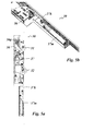
- FIGS. 1a to 1c An embodiment of an active wing lock device 1 mounted in an active wing 10 of a two-leaf door is in the FIGS. 1a to 1c shown in its interaction with an associated passive wing lock device which is mounted in the passive wing 110.
- the passive wing lock device 30 of the FIGS. 1 a. 1 b and 1 c has a lock mechanism which is mounted in a lock case 30a.
- the lock case 30a is mounted in a receiving pocket inserted into the passive wing 110.
- the lock mechanism comprises a lock gear with a gear slide 36 which is coupled in terms of gear with a lock nut 37 rotatably mounted in the lock case 30a.
- the gear slide 36 is vertically guided in the lock case up and down.
- the passive wing lock device 30 includes upper and lower latch bars 380o, 380u and lift-out devices 31 and 32 for lifting the latch 11 and latch 12 of an associated active-wing lock device engaging the passive-wing lock device in the locking position.
- the lock transmission with the gear slide 36 serves to drive the upper locking bar 380o and the lower locking bar 380u and to drive the lifting devices 31 and 32.
- the structure and function of the lifting devices 31 and 32 will be explained in more detail below in conjunction with the figures.
- the upper locking bar 380o is coupled to an upper locking bar connection device 38o mounted in the upper section of the lock case 30a.
- This upper connection device 38o is connected to the transmission slide 36 via a Reverse gear 36g connected.
- the reverse gear 36g is a gear transmission.
- the upper end of the gear slider 36 is formed as a rack and the upper locking bars connecting piece 380 also has a rack.
- a gear mechanism is rotatably mounted in a lock housing fixed pivot bearing. The gear device meshes with the linearly guided in the lock housing racks of gear slide 36 and locking bars connection device 38o.
- the two racks are facing each other in parallel aligned with intermediate gear mechanism, so that the two racks move in opposite directions in the vertical direction. This implies that upon a displacement of the gear slide 36 upwards, the upper locking bar connection device 38o is moved down and the locking bar connecting device 38o is moved upwards by means of a displacement of the gear slide 36.
- the lower latch bar 380u is coupled to a lower latch bar terminal 38u mounted in the lower portion of the latch box 30a.
- This lower locking bar connection device 38u is coupled in the same direction with the transmission slide 36, so that upon displacement of the transmission slide 36 upwards the lower locking bar connection device mit compiler and with a displacement of the transmission slide 36 down the locking bar connection device 38u down mitmaschine.
- the locking bars 380o and 380u thus driven are mounted vertically directed on the passive wing 110 and indeed linearly displaceable, in each case in a corresponding vertical linear guide, preferably concealed in the frame the passive wing displaceable.
- the locking bars 380o and 380u are each movable in opposite directions vertically up and down by their motion-resistant coupling to their associated connection device 38o or 38u via the actuation of the gear slide 36.
- the upper end of the upper latch bar 380o cooperates with a latch receiving recess formed in the upper rail of the stationary frame of the door.
- the lower end of the lower latch bar 380u cooperates with a latch receiving recess formed in the bottom.
- the free upper end of the locking bar engages in the upper latch receiving recess.
- the free lower end of the latch bar engages the lower latch receiving recess.
- the latch lifting device 31 serves to cooperate with the latch 11 of the active wing lock device 1.
- the interaction consists in that the latch lifting device 31 returns the latch 11 to the lock case 1a of the active wing lock device 1, in which the latch lifting device 31 locks the latch 11 pressurized while pushing back until the latch 11 is completely inserted into the lock case 1 a of the active wing lock device 1.
- the trap lifting device 31 has a latching actuating slide 31 a, which is driven by the gear slide 36 via a lever device 31 h.
- the lever device 31 When the transmission slide 36 is pushed upwards, the lever device 31 is swung out so that the trailing edge of the actuating slide 31 a extends.
- the lever means 31 is pivoted h, so that the trailing control slide 31a is retracted again.
- the latch lifting device 32 is used for unlocking and retracting the bolt 22 of the active lock device 1.
- the latch lifting device 32 has in a corresponding manner a latch actuating slide 32a, which is drive-connected via a lever gear 32h with the gear slider 36.
- a latch actuating slide 32a which is drive-connected via a lever gear 32h with the gear slider 36.
- the latch 22 After the latch 22 is unlocked, it is moved back into the lock case 1 a of the active wing lock device by further pressurization, which acts on the front side of the latch 22.
- the lever mechanism 32h of the latch actuating slide 32a When pivoting back the lever mechanism 32h of the latch actuating slide 32a is then retracted. This happens because the gear slide 36 is moved in the vertical direction down.
- a linear guide means 32b of the latch actuating slide 32a intended in the lock case 30a.
- the linear guide device 32b is directed horizontally in the lock case 30 so that the lock operating slide 32a can be moved in and out horizontally.
- a correspondingly linear guide device can also be designed for the trailing control slide 31 a of the lever 31 in the lock case 30 a, as z. Tie Figures 6a and 6b is shown for the embodiment shown there.
- the latch lifting device 32 is also referred to as a latch unlocking and or retracting. It can be designed both for unlocking and for retracting the bolt, as in the in the FIGS. 1a . 1b and 1c illustrated case.
- the latch lifting device 32 may be formed in other embodiments but also only as a latch retracting device.
- a separate device or at least a separate unlocking mechanism can be provided, which can be optionally also driven as a time delay by the gear slide 36 via the same lever means 32h or another separate lever means or via another gear. This is especially true if the latch 22 is not provided with a release pin mounted in the latch, ie if another trigger element, for. B. separately from the latch 22, z. B.
- the latch lifting device 32 may also be designed as unlocking device in modified embodiments, ie the latch actuating slide 32a can then switch off the locking by appropriate pressurization of the triggering mechanism.
- the retraction of the bolt can optionally be replaced by another mechanism z. B. done with a corresponding spring action of the bolt.
- the spring device in question can on the lock box 1a the active wing lock device but also be supported on the passive wing lap box 1 a.
- the latch lifting device 31 is also referred to as a latch unlocking and / or retracting device. She can, as in the FIGS. 1a . 1b and 1c illustrated case, be designed only as a fall-back device for a case 11, which is designed as a spring-loaded in the extension direction conventional latch, which is not self-locking.
- the spring-loaded latch 11 has a prism-shaped end portion having an inlet slope, so that when pulling the active wing 10, that is, when the active wing 10 is pulled or pressed into the closed position, the latch 11 abuts the inlet slope on the frame of the passive wing 110 and against the spring loading the latch 11 is retracted.
- the slope facing away from the inlet slope of the latch 11 is not designed as a slope, but as a parallel to the wing plane blocking surface, so that an active operation of the latch 11 is required for opening the door or in a modified embodiment in which the latch 11 with a Door opener trap cooperates, the door latch is actuated.
- an electric door opener can be arranged in the passive wing lock device. The latch 11 can then interact with the door latch case and the door can be released from the closed position by electrical actuation of the latch opener.
- the latch 11 may also be designed as a self-locking latch - as a so-called latch bolt.
- the latch bolt can occupy three positions, namely a first retracted into the lock case 1a position a second extended from the lock case position comparable to the extended position in conventional lock traps and a third position in which the latch bolt is far extended and locked at the same time and / or at least locked acts. In this third position, the latch bolt is extended approximately twice as far as a conventional latch in its extended position. In addition, in this widely extended third position of the latch bolt, as already mentioned, locked. It should be noted on the FIGS. 7a and 7b showing an embodiment in which the trap 11 is formed as such a latch bolt.
- the trap lifting device 31 is designed as a latch unlocking and retracting means, ie the traps actuating slide 31 a serves to unlock the latch bolt 11 in a first phase of the lifting operation and drive back the latch bolt in the course of the lifting operation.
- Unlocking takes place in that the release pin 11 a, which is slidably mounted in the latch bolt, is first retracted by the latching actuating slide 31 a, ie, first in the locking position of the latch bolt 11 protruding free end of the trigger pin 11 a through the latch actuating slide 31st a retracted.
- By retracting the unlocking of the bolt 11 takes place, so that the latch bolt is moved back under further pressurization by the trailing control slide 31 a.
- latch lifting device 31 is designed only as unlocking or only as a retracting device.
- the return or unlocking can be done via a separate device. The same applies as described above for the bolt lifting device 32 in connection with the unlocking or retraction of the bolt.
- FIGS. 2a and 2 B is one opposite the FIGS. 1a . 1b and 1c modified embodiment shown in which the trap lever 39 is modified.
- the trailing actuating slide 31 a has an actuating plate which is hinged to a driven-side actuating lever of the lever mechanism 31 b.
- the actuating lever has a fixed in the lock case 30 a pivot bearing and is comparable to the FIGS. 1a . 1b and 1c actuated by the transmission slide 36, but structurally modified by a mounted on the operating lever pressure pin is guided in a slot in the transmission slide 36.
- FIGS. 1a . 1b and 1c acts a control edge of the Gear slide 36 together with the pressure pin of the actuating lever, wherein the control edge is formed in the edge contour of the spool 36.
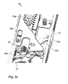
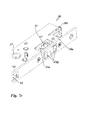
- FIGS. 3a and 3b is one opposite the FIGS. 1a . 1b and 1c modified embodiment shown in which the latch lifting device 32 is modified.
- the bolt actuating slide 32a has a plate-shaped base body, which is guided horizontally in the edge in the fixed in the lock case 30a linear guide device 32b.
- the operating lever of the operating gear 32h is similar to that in Figs FIGS. 2a and 2 B guided in a slot in the gear slider 36 with the pressure pin mounted on the gear lever.
- the latch lifting device 32 is structurally similar as in the embodiment of FIGS. 3a and 3b ,
- the trap lifting device 31 is in the embodiment of Figures 6a and 6b as well as the embodiment of FIGS. 7a to 7d across from the embodiments of the FIGS. 1a . 1b and 1c and the FIGS. 2a and 2 B modified in such a way that the trap lifting device 31 has a sensor device 32 t, with which it is detected whether the case 22 in the lock case 30 a of the passive wing lock device is retracted or extended or is just retracted or extended.
- the trap lifting device 31 has as in the Figures 6a and 6b and even better in the FIGS. 7a to 7d can be seen a trap actuating slide 31 a, which is guided horizontally with its plate-shaped base body in the fixed in the lock case linear guide device 31 b.
- a sensor plate 31 tp is displaceably guided in the linear guide device 31 b.
- the sensor plate 31 tp has at its front end edge two contact plates which come into contact with the case 11.
- the sensor plate 31 tp is acted upon via a spring, in the illustrated case a leg spring, to the outside.
- the spring is dimensioned so that it is suppressed when retracting the case 11 and the case takes the sensor plate 31 tp in abutment with the contact plates.
- the sensor plate 31 tp has at its in the Figures 6a and 6b lower edge region on a lateral actuating edge, which interacts with the oblique-angled actuating edge of a plate-shaped detection element 31 te, which is movably mounted in a fixed housing in the lock case.
- the detection element 31 te has an extension which engages in a arranged in the lock housing 1a light sensor 31 s when the sensor plate 31tp enters the lock housing 30a.
- the sensor device 31t Another possible function of the sensor device 31t is that e.g. can be monitored via a central office, whether the two-leaf door is closed and locked. As regards the locking monitoring, this applies to embodiments in which the case is designed as a latch bolt and for embodiments in which a corresponding sensor device is additionally or alternatively provided in the region of the bolt lifting device 32.
- FIG. 12 shows an embodiment of the passive wing lock device with a sensor device 31 s, with respect to the sensor device 31 t of the embodiment of FIGS. 7a to 7f is modified.
- the sensor device 31 s of FIG. 12 serves the sensor device 31 s of FIG. 12 for detecting whether the latch 22 is retracted or extended in the lock box 30a of the passive wing lock mechanism, or is being retracted or retracted.
- the sensor device 31 s is composed of a light sensor 31 se and a sensor stylus 31 st together.
- the light sensor 31 se is an optical sensor. He has a U-shaped receptacle into which engages the free end of the sensor button 31 st.
- FIGS. 12 shows an embodiment of the passive wing lock device with a sensor device 31 s, with respect to the sensor device 31 t of the embodiment of FIGS. 7a to 7f is modified.
- the sensor device 31 s is composed of a light sensor 31 se and a sensor stylus 31 st together.
- FIG. 12 the sensor button not as a slide, but designed as a two-armed lever.
- the sensor button 31 st in FIG. 12 acts directly with the light sensor 31 se.
- FIGS. 7a to 7f is between the light sensor 31 s and the button 31 tp and a wedge-shaped transmission member 31 te provided.
- the sensor button 31 st of the sensor device in FIG. 12 is designed as a sensing lever which pivotable about a lock box fixed axis 31 sta Lock case is stored.
- the sensing lever 31 st is designed as a two-armed lever.
- the first lever arm 31 stt serves to key the latch 11 of the active wing lock device.
- the second lever arm 31 sts has a hook-like extension which projects into the U-shaped receptacle of the light sensor 31 s.
- the first lever arm 31 stt of the sensing lever 31 st projects into the predetermined space of the passive wing lock, which is provided for receiving the latch 11 of the active wing lock.
- FIG. 12 spring not shown, which acts on the sensing lever 31 in the direction of the outward direction.
- the sensor device operates as follows: In the closed position of the door, the latch 11 of the active lock device moves spring-loaded into the space provided for receiving the latch 11 of the passive wing lock device. In this case, the case 11 comes with the first lever 31 stt of the sensing lever 31 st in contact, so that the sensing lever 31 st is pivoted by the entering into the passive wing lock device case 11 about its axis of rotation 31 sta around.
- the hook-like extension of the feeler lever 31 st which projects into the light sensor 31 s when the door is open, then, when the trap 11 has reached its closed position, leave the U-shaped receptacle of the light sensor 31 se.
- the light sensor 31 se outputs depending on its operation or non-operation corresponding electrical signals, which are processed by an electrical signal processing system.
- the interaction of the sensing lever 31 st and the light sensor 32se may also be provided so that the sensing lever 31 st in the light sensor 31 se engages when the case 11 is retracted into the receiving space of the passive lock box. With the sash open The hook-like extension of the feeler lever 31 then stalls outside the recording of the light sensor 31. Also in this modified embodiment, the light sensor 31 se depending on its operation or non-operation corresponding electrical signals from which are processed by an electrical signal processing system.
- FIG. 13 shows an embodiment of the passive wing lock device with two further sensor devices 32s and 37s, one of which is associated with the latch 22 and the other of the lock nut 37.
- the sensor device 32t is used to detect whether the latch 22 is retracted or extended in the lock case 30a of the passive-wing lock device or is being retracted or extended.
- This sensor device 32t has an analog construction to the sensor device 31t FIG. 12 which detects the position of the trap.
- the sensor device consists of a light sensor 31 se and a sensor button 31 st.
- the sensor button 31 st is also designed as a two-armed lever which is pivotally mounted in the lock case about an axis 31 sta.
- the sensor button 31 st has a first lever arm 31 stt, which is used for sensing the latch 22, and a second lever arm 31 sts, which cooperates with the light sensor 31 se.
- the sensor device 37s serves to detect an actuation of the lock nut 37.
- a light sensor 37se is provided.
- the lock nut 37 has a radially projecting arm 37fs which is provided with an extension formed as an angled edge. In the rest position of the passive wing lock device, the extension 37fs projects into the U-shaped receiving area of the light sensor 37se. If the actuation handle is actuated by a user on the passive wing lock, the locknut becomes 37 shot. In this case, the edge-like extension 37fs of the lock nut 37 then leaves the receiving area of the electric light sensor 37se. The light sensor 37se then outputs a corresponding electrical signal that can be processed by an electrical signal processing system. By means of the sensor device 37s, it can be detected whether the passive wing lock has been opened by the manual actuation of a handle or push rod arranged on the passive wing.
- a sensor device 36s which serves to detect a movement of the transmission slide 36.
- a light sensor 36se is provided.
- the gear slider 36 has a projecting projection 37fs.
- the extension 37f is outside the U-shaped receiving area of the light sensor 37se. If the passive wing lock is actuated by the actuating handle by a user or by the motorized actuating device, the gear slide 36 is thereby pushed upwards.
- the extension 36fs of the gear slider 36 enters the receiving area of the electric light sensor 36se.
- the light sensor 36se then outputs a corresponding electrical signal that can be processed by an electrical signal processing system.
- the sensor device 37t it can be detected whether the passive wing lock has been opened by the manual actuation of a handle or push rod arranged on the passive wing.
- the sensors 31 se, 32se, 36se and 37se are mounted on a common plate mounted in the lock box.
- an electronic device for evaluating and / or processing the data of the sensors is provided.
- This electronic device can be in one be arranged separate housing. This separate housing may preferably be arranged adjacent to the lock case coupled.
- Using the information from the sensors 31 s and 32 s can be monitored, for example, in a public building by a central, whether a two-leaf door is open or is in the closed position or locked. Furthermore, it can be tracked by a monitoring center, whether a door has been unlocked by operating the nut or by activating the motorized actuator.
- the position of the lock nut remains unchanged and the signal of the sensor 37s remains unchanged, while an unlocking by operating the handle rotation of the lock nut 37 results and is detected by the nut associated sensor 37s.
- the sensors can also be used to control the motorized actuator when unlocking the lock device. By means of the sensors 31 se and 32se, it can be detected during unlocking whether the latch 11 or the bolt 22 no longer protrude into the associated receptacles of the passive wing lock, whereupon the motorized actuating device can be deactivated.
- the operation of the passive wing lock device 30 can be done via a manual control device, not shown in the figures.
- the manual actuating device can be designed as a rotary handle which can be inserted into the lock nut 37, wherein the lock nut 37 forms a part of the lock transmission.
- the rotary handle can be designed as a conventional pusher or as a push rod, a so-called panic push rod. Both the pusher and the push rod may have a corresponding rotary connection, which is rotatably inserted for coupling with the lock gear in the lock nut 37.
- the lock nut 37 By operating the actuator, the lock nut 37 is rotated and thereby actuates the lock gear. With the operation of the lock transmission of the transmission slide is moved. With the operation of the lock transmission, the locking bars 38e, 38u are displaced vertically in opposite directions depending on the direction of rotation of the actuation. In addition, the latch lifting device 31 and the latch lifting device 32 are actuated simultaneously or with a delay in the operation of the lock transmission.
- the lock transmission is designed so that an actuation of the lock nut 37 in one direction, the upper locking bars 38o up device and the lower locking bar connection device 38u shifts downward, and consequently the respective locking bars 380o and 380u are each extended so moved into their locking position.
- the lifting means 31, 32 for lifting the latch 11 and the bolt 12 are thereby actuated via the lock gear so that the trailing control slide 31 a and the bolt actuating slide 32 a in the Lock housing 30a of the passive lock device 30 are retracted.
- a motor actuator which in contrast has a linear output.
- the linear drive can be coupled directly to the transmission slide 36.
- the operation of the lock gear by the linear drive of the motorized actuator then acts in the same manner as when the lock gear is operated via rotation of the lock nut 37, as described above.
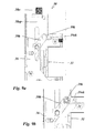
- FIGS. 5a and 5b show the passive wing lock device 30 with a arranged at the lower end of the lock case 30a such motor actuator 37m.
- FIGS. 5c and 5d show the coupled to the transmission slide coupling slide 37k, without the motor actuator 37m is coupled.
- the embodiment with the motorized actuator may be optional.
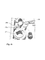
- FIG. 4b shows the blocking member 39b in the blocking position in a tampering attempt.
- the gear slider 36 has been made by manipulation Pressurizing the locking bars relative to the position in FIG. 4a moved a little way up and is held against further upward displacement by the blocking member 39b.
- Figure 4c shows the blocking member 39 b in the release position in which it is out of engagement of the gear slide 36.
- the blocking member 39b is displaced in this release position by the operation of the lock nut 37 in that by rotation of the lock nut 37 in the figure in the figure in the counterclockwise direction of the cam follower 37 fixed driver 37a cooperating with the blocking member 39b and the blocking member 39b in the representation in the Figure 4c moved to the left.
- This first embodiment of the anti-tamper device in the FIGS. 4a to 4c thus acts on the transmission slide 36 and thus on both locking bars; However, it requires an actuator on the lock nut 37.
- a second embodiment of a tamper protection device is in the FIGS. 9a and 9b shown. This manipulation protection device requires no operation of the lock transmission via the lock nut 37, but the operation of the lock gear can also be via a linear output of the gear slide, for example via the motorized actuator 37m of FIGS. 5a and 5b respectively.
- This embodiment of the anti-tamper means sees in the embodiment of FIGS. 9a and 9b a link device 39k, which is formed between the upper locking bar connecting device 38o and the gear slider 36.
- the gate device 39k has a cam slot 39ok, which is formed with the plate-shaped main body of the upper locking bar connecting device 38o.
- the link mechanism 39k further comprises a lever 39h, which in a castle box fixed pivot bearing is mounted and has a guide pin at one end, which engages in the slot slot 39ok and at its other end has a guide pin which engages in a slot formed in the gear slide 36.
- the gate device 39k described above thus forms in the embodiment described above FIGS. 9a and 9b a manipulation protection device for the upper locking bar 380o.
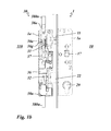
- a tamper protection device provided, as in the Figures 10a and 10b is shown.
- This manipulation protection device has a blocking lever 39p, which is mounted in a lock box-fixed pivot bearing. He is spring-loaded and / or gravitational in the in FIG. 10a with its free end to the left-facing position.
- a blocking pin 39s which is resistant to movement with the gear slide 36, engages in the hook-shaped recess of the blocking lever 39p in this position.
- FIG. 10c shows the situation in case of a manipulation attempt.
- the plate-shaped base body of the lower locking bar connection device 38u is driven by the upwardly acting pressurization of the locking bar 380u in the oblong holes driven up and comes into abutment against the lower bottom of the blocking lever 39p.
- a displacement of the lower locking bar 380u is counteracted in a manipulation attempt and the lower locking bar 380u is blocked in the extended position.
- the vertical movement of the lower bar connecting device 38a is thus not transmitted to the transmission slide 36.
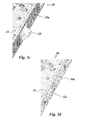
- FIG. 11 shows an eleventh embodiment of the passive wing lock device with a tamper protection device for the lower locking bar 380u, wherein the anti-tamper according to FIG. 11 opposite the anti-tamper device according to FIGS. 10a to 10c is modified.
- the manipulation protection device has a blocking lever 39p, which is mounted in a lock box-fixed pivot bearing.
- the blocking lever has a blocking stop 39b which, in the blocking position, cooperates with the lower locking bar connection device 38u, as in FIG FIG. 11 is shown.
- the blocking stopper 39b is formed as an abutment step of the side edge of the blocking lever 39p.
- the manipulation attempt is in FIG. 11 shown.
- FIG. 11 shows the tamper protection in a tampering attempt.
- the manipulation protection is that when pressure is applied to the lower locking bars connecting device 38u, the lower locking bar connecting device 38u comes into abutment against the blocking stop 39b of the blocking lever 39p and is thus blocked against further displacement in the vertical upward direction. As a result, no vertical movement is transmitted to the gear slider 36 through the lower latch bars 38u.
- the blocking lever 39p is provided with a cam slot into which a cam pin 36k of the gear slider 36 engages. If, in the event of a proper unlocking by operation of the nut 37 or the motor actuator 37m of the transmission slide 36 is displaced upwards for unlocking, the gear shifter fixed pin 36k moves vertically upwards and runs in the sliding slot 39k of the blocking lever, whereby the blocking lever 39p is pivoted in the illustrated case counterclockwise.
- the blocking lever 39p projects in the pivoted then no longer in a blocking manner in the Movement range of the lower locking bar connecting device 38u into it. Simultaneously with the pivoting of the blocking lever 39p, a lever 38h is pivoted.
- the lever 38h is pivotally mounted in the lock case 38a about a lock case fixed axis 38a and cooperates with a foot side arranged on the transmission slide 36 actuation stop.
- the lever 38 When pushing up the gear slide 36, the lever 38 is pivoted clockwise in the illustrated case.
- the lever 38h is formed as an operating lever of the lower locking bar connecting device 38u. He interacts with its free end with a corresponding stop on the lower locking bar connection device 38u together.
- the lower locking bar connecting device 38u is thus moved in the same direction with the transmission slide 36 and retracted the lower locking bar in the lock case.
Landscapes
- Engineering & Computer Science (AREA)
- Mechanical Engineering (AREA)
- Business, Economics & Management (AREA)
- Emergency Management (AREA)
- Physics & Mathematics (AREA)
- Electromagnetism (AREA)
- Structural Engineering (AREA)
- Lock And Its Accessories (AREA)
Applications Claiming Priority (5)
| Application Number | Priority Date | Filing Date | Title |
|---|---|---|---|
| DE102012017819 | 2012-09-04 | ||
| DE102012017812 | 2012-09-04 | ||
| DE102012017810 | 2012-09-04 | ||
| DE102012017811 | 2012-09-04 | ||
| DE102012017818 | 2012-09-04 |
Publications (2)
| Publication Number | Publication Date |
|---|---|
| EP2703583A2 true EP2703583A2 (fr) | 2014-03-05 |
| EP2703583A3 EP2703583A3 (fr) | 2015-03-11 |
Family
ID=49084913
Family Applications (4)
| Application Number | Title | Priority Date | Filing Date |
|---|---|---|---|
| EP13183050.7A Active EP2703585B2 (fr) | 2012-09-04 | 2013-09-04 | Dispositif de serrure pour vantail passif doté d'un dispositif de tringlerie avec dispositif de protection contre la manipulation |
| EP13183052.3A Active EP2703586B1 (fr) | 2012-09-04 | 2013-09-04 | Dispositif de serrure pour vantail passif doté d'un dispositif de détection |
| EP13183048.1A Active EP2703584B1 (fr) | 2012-09-04 | 2013-09-04 | Dispositif de serrure pour vantail passif doté d'un dispositif d'actionnement motorisé |
| EP13183043.2A Withdrawn EP2703583A3 (fr) | 2012-09-04 | 2013-09-04 | Dispositif de serrure pour vantail passif avec un dispositif de retrait de pêne comportant un poussoir à ressort d'actionnement du pêne |
Family Applications Before (3)
| Application Number | Title | Priority Date | Filing Date |
|---|---|---|---|
| EP13183050.7A Active EP2703585B2 (fr) | 2012-09-04 | 2013-09-04 | Dispositif de serrure pour vantail passif doté d'un dispositif de tringlerie avec dispositif de protection contre la manipulation |
| EP13183052.3A Active EP2703586B1 (fr) | 2012-09-04 | 2013-09-04 | Dispositif de serrure pour vantail passif doté d'un dispositif de détection |
| EP13183048.1A Active EP2703584B1 (fr) | 2012-09-04 | 2013-09-04 | Dispositif de serrure pour vantail passif doté d'un dispositif d'actionnement motorisé |
Country Status (3)
| Country | Link |
|---|---|
| EP (4) | EP2703585B2 (fr) |
| ES (1) | ES2700546T3 (fr) |
| PL (2) | PL2703586T3 (fr) |
Cited By (14)
| Publication number | Priority date | Publication date | Assignee | Title |
|---|---|---|---|---|
| DE102014225813A1 (de) | 2014-12-15 | 2016-06-16 | Aug. Winkhaus Gmbh & Co. Kg | Gegenschloss eines Treibstangenschlosses |
| DE102015000605A1 (de) * | 2015-01-16 | 2016-07-21 | Assa Abloy Sicherheitstechnik Gmbh | Schlosseinrichtung für eine Tür oder ein Fenster |
| EP3118402A1 (fr) * | 2015-07-13 | 2017-01-18 | PaX AG | Dormant de porte ou de fenetre |
| EP3118396A1 (fr) * | 2015-07-15 | 2017-01-18 | Heinrich Strenger GmbH & Co. KG | Pene dormant comprenant un moteur electrique |
| EP3336288A1 (fr) * | 2016-12-14 | 2018-06-20 | GEZE GmbH | Dispositif de verrouillage pour une porte à deux battants |
| EP3406832A1 (fr) * | 2017-05-23 | 2018-11-28 | GEZE GmbH | Taquets pour une serrure antipanique |
| EP3543438A1 (fr) * | 2018-03-22 | 2019-09-25 | dormakaba Deutschland GmbH | Dispositif de fermeture ayant au moins une barre de verrouillage |
| EP3543437A1 (fr) * | 2018-03-22 | 2019-09-25 | dormakaba Deutschland GmbH | Dispositif formant serrure pourvu d'une serrure pour une porte à battants mobiles |
| EP3702557A1 (fr) * | 2019-02-28 | 2020-09-02 | Talleres de Escoriaza, S.A.U. | Contre-serrure pour battant inactif d'une double porte |
| DE102022100121A1 (de) | 2022-01-04 | 2023-07-06 | Assa Abloy Sicherheitstechnik Gmbh | Selbstverriegelndes Schloss mit motorischer Entriegelung |
| DE102022106474A1 (de) | 2022-03-21 | 2023-09-21 | Gu Automatic Gmbh | Vorrichtung zur Verriegelung eines Türflügels |
| EP4459085A1 (fr) * | 2023-05-05 | 2024-11-06 | dormakaba Deutschland GmbH | Dispositif de fermeture à verrouillage automatique avec une structure simplifiée d'une unité d'éjection |
| DE102024107453A1 (de) * | 2024-03-15 | 2025-09-18 | Assa Abloy Sicherheitstechnik Gmbh | Treibriegelschlos mit motorischer und manueller Entriegelung |
| DE102024136930B3 (de) * | 2024-12-10 | 2025-12-31 | Assa Abloy Sicherheitstechnik Gmbh | Türschloss mit Sensorvorrichtung mit Taster auf Platine |
Families Citing this family (7)
| Publication number | Priority date | Publication date | Assignee | Title |
|---|---|---|---|---|
| PL2703586T3 (pl) | 2012-09-04 | 2019-03-29 | Assa Abloy Sicherheitstechnik Gmbh | Układ zamka z układem czujników do skrzydła pasywnego |
| DE102015206417B4 (de) | 2015-04-10 | 2020-01-16 | Geze Gmbh | Schaltschloss |
| AT16183U1 (de) * | 2017-08-03 | 2019-03-15 | Roto Frank Ag | Schloss |
| EP3543439B1 (fr) * | 2018-03-22 | 2024-01-24 | dormakaba Deutschland GmbH | Procédé pour un ensemble serrure |
| EP3543965B1 (fr) | 2018-03-22 | 2022-07-06 | dormakaba Deutschland GmbH | Ensemble serrure et procédé pour la vérification d'un ensemble serrure |
| IT201900010287A1 (it) * | 2019-06-27 | 2020-12-27 | Prefer Srl | Gruppo-serratura per serramenti |
| DE102024107707A1 (de) * | 2024-03-18 | 2025-09-18 | Assa Abloy Sicherheitstechnik Gmbh | Riegel- und/oder Fallenaushebeeinrichtung |
Citations (1)
| Publication number | Priority date | Publication date | Assignee | Title |
|---|---|---|---|---|
| EP0849425B1 (fr) | 1996-12-18 | 2000-03-01 | DORMA GmbH + Co. KG | Dispositif de déverrouillage et verrouillage pour une porte à deux battants |
Family Cites Families (39)
| Publication number | Priority date | Publication date | Assignee | Title |
|---|---|---|---|---|
| DE1703470B1 (de) * | 1968-05-25 | 1972-02-03 | Eaton Gmbh | Doppeltwirkendes Paniktuerschloss fuer zweifluegelige Tueren |
| US3765198A (en) | 1970-11-04 | 1973-10-16 | Blumcraft Pittsburgh | Panic device for a door |
| DE2611359C2 (de) * | 1976-03-18 | 1983-08-04 | Scovill Sicherheitseinrichtungen Gmbh, 5620 Velbert | Treibstangenverschluß für Türflügel |
| DE3142959C2 (de) | 1981-08-04 | 1985-06-05 | BKS Sicherheitstechnik GmbH, 5040 Brühl | Treibstangenverschluß für Türen |
| DE8502219U1 (de) | 1985-01-29 | 1985-05-02 | BKS GmbH, 5620 Velbert | Treibriegelverschluss fuer zweifluegelige tueren, insbesondere mit panikfunktion |
| AU630264B2 (en) | 1990-01-24 | 1992-10-22 | Lenlok Hales Pty. Ltd. | Improved self lock mechanism |
| DE9211077U1 (de) | 1992-08-18 | 1992-10-29 | BKS GmbH, 5620 Velbert | Panik-Treibstangenschloß |
| AT399015B (de) * | 1993-08-23 | 1995-03-27 | Roto Frank Eisenwaren | Schloss, insbesondere mehrriegelschloss, mit elektrischem antrieb |
| DE4341252A1 (de) * | 1993-12-03 | 1995-06-08 | Dieter Arndt | Schließvorrichtung einer Tür |
| GB2286420B (en) | 1994-02-03 | 1996-12-18 | Fred Duncombe Limited | Emergency door latch mechanism |
| DE9409846U1 (de) | 1994-06-21 | 1994-09-15 | Bks Gmbh, 42549 Velbert | Panik-Treibstangenschloß |
| EP0722156B1 (fr) * | 1994-12-30 | 1999-03-17 | FRITZ FUSS GmbH & Co. | Procédé pour armer une installation de signalisation d'intrusion utilisant une serrure encastrée avec blockage intégré |
| DE19652599C2 (de) * | 1996-12-18 | 2000-05-18 | Dorma Gmbh & Co Kg | Ent- und Verriegelung für eine einen Standflügel und einen Gangflügel aufweisende Tür |
| DE19730552C1 (de) * | 1997-07-17 | 1999-04-29 | Weru Ag | Einrichtung zum Entriegeln eines mechanisch selbstverriegelnden Mehrfachschlosses |
| AT406883B (de) | 1998-11-11 | 2000-10-25 | Roto Frank Eisenwaren | Sperre gegen das zurückdrücken eines ausgeschobenen riegels |
| DE19958470C1 (de) | 1999-12-04 | 2001-10-31 | Olaf Clausen | Verriegelung für eine mehrflügelige Tür |
| DE20212622U1 (de) | 2002-08-14 | 2002-12-05 | Bks Gmbh, 42549 Velbert | Treibriegelschloß |
| DE10310085B4 (de) * | 2003-03-06 | 2005-12-15 | Carl Fuhr Gmbh & Co. Kg | Schließanlage, insbesondere Türverschluss, Fensterverschluß und dergleichen |
| DE20307121U1 (de) | 2003-04-30 | 2003-07-10 | Gretsch-Unitas GmbH Baubeschläge, 71254 Ditzingen | Schloss |
| FR2866048B1 (fr) | 2004-02-05 | 2008-03-14 | Bricard Sa | Coffre principal d'une serrure multipoints muni d'une butee de tringle |
| DE102004009973B4 (de) | 2004-03-01 | 2007-03-22 | Wilh. Schlechtendahl & Söhne GmbH & Co KG | Gegenkasten für ein Paniktürschloß |
| DE102005015248B4 (de) * | 2005-04-02 | 2010-01-21 | Wilka Schließtechnik GmbH | Standflügelschloss mit einem elektrischen Türöffner |
| DE202006001383U1 (de) | 2006-01-27 | 2006-04-13 | Bks Gmbh | Treibriegelschloß |
| DE102006011263B4 (de) * | 2006-03-10 | 2008-04-24 | Assa Abloy Sicherheitstechnik Gmbh | Verriegelungssystem für eine Tür |
| DE202006004553U1 (de) * | 2006-03-20 | 2006-06-08 | Carl Fuhr Gmbh & Co. Kg | Schließanlage für eine Tür o.dgl. |
| DE102006060450A1 (de) * | 2006-12-19 | 2008-06-26 | Dorma Gmbh + Co. Kg | Selbstverriegelndes, elektromechanisches Panikschloss |
| DE102006060448A1 (de) | 2006-12-19 | 2008-06-26 | Dorma Gmbh + Co. Kg | Selbstverriegelndes Panikschloss |
| DE102007001691B4 (de) | 2007-01-11 | 2011-01-27 | Assa Abloy Sicherheitstechnik Gmbh | Türöffner |
| DE202007003890U1 (de) | 2007-03-16 | 2008-07-31 | Carl Fuhr Gmbh & Co. Kg | Schloss, insbesondere Panikschloss mit Nussbetätigungsstellungssensor |
| DE202008000919U1 (de) | 2008-01-23 | 2008-04-10 | Carl Fuhr Gmbh & Co. Kg | Schließanlage für eine einen Gangflügel und einen Standflügel aufweisende zweiflügelige Tür |
| DE102008048395A1 (de) | 2008-09-22 | 2010-03-25 | Carl Fuhr Gmbh & Co. Kg | Schließanlage |
| GB2466518B (en) | 2008-12-24 | 2013-09-04 | Assa Abloy Ltd | Lock and handle assemblies |
| DE202009003976U1 (de) * | 2009-03-24 | 2010-08-19 | Kfv Karl Fliether Gmbh & Co. Kg | Ver- und Entriegelung für eine einen Standflügel und einen Gangflügel aufweisende Tür |
| DE102009043962B4 (de) | 2009-09-09 | 2012-08-09 | Wilka Schließtechnik GmbH | Elektrischer Türöffner |
| DE102009044373A1 (de) | 2009-10-30 | 2011-05-05 | Gortat, Manfred, Dipl.-Ing. | Sicherheitsvorrichtung mit Betätigungseinheiten |
| SE535099C2 (sv) | 2009-11-25 | 2012-04-17 | Assa Ab | Lås med blockeringsfunktion |
| DE102011000549A1 (de) | 2011-02-08 | 2012-08-09 | Dorma Gmbh + Co. Kg | Schloss mit einer Falle und einer Zusatzfalle zur Ablaufsicherung einer Riegelbewegung |
| DE202011103840U1 (de) | 2011-07-29 | 2011-11-30 | Carl Fuhr Gmbh & Co. Kg | Schließanlage mit Mehrfachverriegelung für eine Tür |
| PL2703586T3 (pl) | 2012-09-04 | 2019-03-29 | Assa Abloy Sicherheitstechnik Gmbh | Układ zamka z układem czujników do skrzydła pasywnego |
-
2013
- 2013-09-04 PL PL13183052T patent/PL2703586T3/pl unknown
- 2013-09-04 EP EP13183050.7A patent/EP2703585B2/fr active Active
- 2013-09-04 EP EP13183052.3A patent/EP2703586B1/fr active Active
- 2013-09-04 ES ES13183052T patent/ES2700546T3/es active Active
- 2013-09-04 EP EP13183048.1A patent/EP2703584B1/fr active Active
- 2013-09-04 EP EP13183043.2A patent/EP2703583A3/fr not_active Withdrawn
- 2013-09-04 PL PL13183048T patent/PL2703584T3/pl unknown
Patent Citations (1)
| Publication number | Priority date | Publication date | Assignee | Title |
|---|---|---|---|---|
| EP0849425B1 (fr) | 1996-12-18 | 2000-03-01 | DORMA GmbH + Co. KG | Dispositif de déverrouillage et verrouillage pour une porte à deux battants |
Cited By (18)
| Publication number | Priority date | Publication date | Assignee | Title |
|---|---|---|---|---|
| DE102014225813A1 (de) | 2014-12-15 | 2016-06-16 | Aug. Winkhaus Gmbh & Co. Kg | Gegenschloss eines Treibstangenschlosses |
| EP3034726A1 (fr) | 2014-12-15 | 2016-06-22 | Aug. Winkhaus GmbH & Co. KG | Contre-serrure d'une serrure a espagnolette |
| DE102015000605A1 (de) * | 2015-01-16 | 2016-07-21 | Assa Abloy Sicherheitstechnik Gmbh | Schlosseinrichtung für eine Tür oder ein Fenster |
| EP3118402A1 (fr) * | 2015-07-13 | 2017-01-18 | PaX AG | Dormant de porte ou de fenetre |
| EP3118396A1 (fr) * | 2015-07-15 | 2017-01-18 | Heinrich Strenger GmbH & Co. KG | Pene dormant comprenant un moteur electrique |
| EP3336288A1 (fr) * | 2016-12-14 | 2018-06-20 | GEZE GmbH | Dispositif de verrouillage pour une porte à deux battants |
| CN108222699A (zh) * | 2016-12-14 | 2018-06-29 | 盖慈有限公司 | 用于双扇门的闭锁装置 |
| CN108222699B (zh) * | 2016-12-14 | 2019-11-12 | 盖慈有限公司 | 用于双扇门的闭锁装置 |
| DE102017208721A1 (de) | 2017-05-23 | 2018-11-29 | Geze Gmbh | Gegenkasten für ein Paniktürschloss |
| EP3406832A1 (fr) * | 2017-05-23 | 2018-11-28 | GEZE GmbH | Taquets pour une serrure antipanique |
| EP3543438A1 (fr) * | 2018-03-22 | 2019-09-25 | dormakaba Deutschland GmbH | Dispositif de fermeture ayant au moins une barre de verrouillage |
| EP3543437A1 (fr) * | 2018-03-22 | 2019-09-25 | dormakaba Deutschland GmbH | Dispositif formant serrure pourvu d'une serrure pour une porte à battants mobiles |
| EP3702557A1 (fr) * | 2019-02-28 | 2020-09-02 | Talleres de Escoriaza, S.A.U. | Contre-serrure pour battant inactif d'une double porte |
| DE102022100121A1 (de) | 2022-01-04 | 2023-07-06 | Assa Abloy Sicherheitstechnik Gmbh | Selbstverriegelndes Schloss mit motorischer Entriegelung |
| DE102022106474A1 (de) | 2022-03-21 | 2023-09-21 | Gu Automatic Gmbh | Vorrichtung zur Verriegelung eines Türflügels |
| EP4459085A1 (fr) * | 2023-05-05 | 2024-11-06 | dormakaba Deutschland GmbH | Dispositif de fermeture à verrouillage automatique avec une structure simplifiée d'une unité d'éjection |
| DE102024107453A1 (de) * | 2024-03-15 | 2025-09-18 | Assa Abloy Sicherheitstechnik Gmbh | Treibriegelschlos mit motorischer und manueller Entriegelung |
| DE102024136930B3 (de) * | 2024-12-10 | 2025-12-31 | Assa Abloy Sicherheitstechnik Gmbh | Türschloss mit Sensorvorrichtung mit Taster auf Platine |
Also Published As
| Publication number | Publication date |
|---|---|
| EP2703585B1 (fr) | 2019-09-04 |
| EP2703586A3 (fr) | 2015-03-11 |
| EP2703584A2 (fr) | 2014-03-05 |
| EP2703585B2 (fr) | 2022-11-16 |
| EP2703585A3 (fr) | 2015-03-11 |
| PL2703584T3 (pl) | 2020-08-24 |
| ES2700546T3 (es) | 2019-02-18 |
| EP2703584A3 (fr) | 2015-03-11 |
| PL2703586T3 (pl) | 2019-03-29 |
| EP2703583A3 (fr) | 2015-03-11 |
| EP2703585A2 (fr) | 2014-03-05 |
| EP2703586A2 (fr) | 2014-03-05 |
| EP2703584B1 (fr) | 2020-02-12 |
| EP2703586B1 (fr) | 2018-10-24 |
Similar Documents
| Publication | Publication Date | Title |
|---|---|---|
| EP2703586B1 (fr) | Dispositif de serrure pour vantail passif doté d'un dispositif de détection | |
| EP2037063B1 (fr) | Système de verrouillage d'une porte | |
| EP2096241B1 (fr) | Verrou supplémentaire à verrouillage automatique | |
| EP2855807B1 (fr) | Dispositif de serrure de porte pour une porte anti-panique | |
| WO2007104499A2 (fr) | Dispositif de verrouillage pour une porte | |
| EP2673434B1 (fr) | Serrure dotée d'un loquet et d'un loquet supplémentaire destiné à empêcher le déplacement d'un pêne | |
| AT504295A2 (de) | Schlanker gegenkasten für ein paniktürschloss | |
| EP3406832B1 (fr) | Gâche pour une serrure antipanique | |
| EP2924201A1 (fr) | Serrure de porte ou de fenêtre | |
| DE102013000286A1 (de) | Türschlossvorrichtung für eine Tür mit mindestens einem Türflügel | |
| DE19652599C2 (de) | Ent- und Verriegelung für eine einen Standflügel und einen Gangflügel aufweisende Tür | |
| WO2013113854A1 (fr) | Ouvre-porte et porte munie d'un ouvre-porte | |
| EP2820208B1 (fr) | Serrure | |
| EP3045623A1 (fr) | Dispositif de sécurisation de porte | |
| EP2441905A1 (fr) | Serrure | |
| EP2339096A2 (fr) | Serrure à crémone dotée d'une fonction anti-panique et d'un verrouillage multiple | |
| AT504296A2 (de) | Schlanker gegenkasten für ein paniktürschloss | |
| EP2256273A2 (fr) | Crémone-serrure de verrouillage multi-points | |
| AT396164B (de) | Einstemmschloss | |
| EP1953312B1 (fr) | Verrou pour une porte | |
| DE102018115985A1 (de) | Schlossgegenkasten für ein Aktivflügelschloss mit Falzluftausgleich | |
| DE102013012203B4 (de) | Elektrischer Türöffner sowie ein Passivflügelschloss mit einem solchen Türöffner | |
| EP0439478B1 (fr) | Serrure a verrouillage automatique | |
| DE29923398U1 (de) | Schließsystem für Möbel | |
| EP0795665A2 (fr) | Serrure encastrée |
Legal Events
| Date | Code | Title | Description |
|---|---|---|---|
| AK | Designated contracting states |
Kind code of ref document: A2 Designated state(s): AL AT BE BG CH CY CZ DE DK EE ES FI FR GB GR HR HU IE IS IT LI LT LU LV MC MK MT NL NO PL PT RO RS SE SI SK SM TR |
|
| AX | Request for extension of the european patent |
Extension state: BA ME |
|
| PUAI | Public reference made under article 153(3) epc to a published international application that has entered the european phase |
Free format text: ORIGINAL CODE: 0009012 |
|
| PUAL | Search report despatched |
Free format text: ORIGINAL CODE: 0009013 |
|
| AK | Designated contracting states |
Kind code of ref document: A3 Designated state(s): AL AT BE BG CH CY CZ DE DK EE ES FI FR GB GR HR HU IE IS IT LI LT LU LV MC MK MT NL NO PL PT RO RS SE SI SK SM TR |
|
| AX | Request for extension of the european patent |
Extension state: BA ME |
|
| RIC1 | Information provided on ipc code assigned before grant |
Ipc: E05B 63/24 20060101ALI20150204BHEP Ipc: E05B 17/20 20060101ALI20150204BHEP Ipc: E05C 7/04 20060101AFI20150204BHEP Ipc: E05C 9/04 20060101ALN20150204BHEP Ipc: E05B 65/10 20060101ALI20150204BHEP Ipc: E05B 47/00 20060101ALN20150204BHEP |
|
| 17P | Request for examination filed |
Effective date: 20150911 |
|
| RBV | Designated contracting states (corrected) |
Designated state(s): AL AT BE BG CH CY CZ DE DK EE ES FI FR GB GR HR HU IE IS IT LI LT LU LV MC MK MT NL NO PL PT RO RS SE SI SK SM TR |
|
| 17Q | First examination report despatched |
Effective date: 20180322 |
|
| STAA | Information on the status of an ep patent application or granted ep patent |
Free format text: STATUS: THE APPLICATION IS DEEMED TO BE WITHDRAWN |
|
| 18D | Application deemed to be withdrawn |
Effective date: 20181002 |