EP2703761A1 - Élément de lavage de gaz et conduite d'alimentation en gaz correspondante - Google Patents
Élément de lavage de gaz et conduite d'alimentation en gaz correspondante Download PDFInfo
- Publication number
- EP2703761A1 EP2703761A1 EP12181902.3A EP12181902A EP2703761A1 EP 2703761 A1 EP2703761 A1 EP 2703761A1 EP 12181902 A EP12181902 A EP 12181902A EP 2703761 A1 EP2703761 A1 EP 2703761A1
- Authority
- EP
- European Patent Office
- Prior art keywords
- gas
- connection
- plug
- supply line
- connection piece
- Prior art date
- Legal status (The legal status is an assumption and is not a legal conclusion. Google has not performed a legal analysis and makes no representation as to the accuracy of the status listed.)
- Granted
Links
Images



Classifications
-
- C—CHEMISTRY; METALLURGY
- C21—METALLURGY OF IRON
- C21C—PROCESSING OF PIG-IRON, e.g. REFINING, MANUFACTURE OF WROUGHT-IRON OR STEEL; TREATMENT IN MOLTEN STATE OF FERROUS ALLOYS
- C21C5/00—Manufacture of carbon-steel, e.g. plain mild steel, medium carbon steel or cast steel or stainless steel
- C21C5/28—Manufacture of steel in the converter
- C21C5/42—Constructional features of converters
- C21C5/46—Details or accessories
- C21C5/48—Bottoms or tuyéres of converters
-
- B—PERFORMING OPERATIONS; TRANSPORTING
- B22—CASTING; POWDER METALLURGY
- B22D—CASTING OF METALS; CASTING OF OTHER SUBSTANCES BY THE SAME PROCESSES OR DEVICES
- B22D1/00—Treatment of fused masses in the ladle or the supply runners before casting
- B22D1/002—Treatment with gases
-
- C—CHEMISTRY; METALLURGY
- C21—METALLURGY OF IRON
- C21C—PROCESSING OF PIG-IRON, e.g. REFINING, MANUFACTURE OF WROUGHT-IRON OR STEEL; TREATMENT IN MOLTEN STATE OF FERROUS ALLOYS
- C21C5/00—Manufacture of carbon-steel, e.g. plain mild steel, medium carbon steel or cast steel or stainless steel
- C21C5/28—Manufacture of steel in the converter
- C21C5/30—Regulating or controlling the blowing
- C21C5/34—Blowing through the bath
-
- C—CHEMISTRY; METALLURGY
- C21—METALLURGY OF IRON
- C21C—PROCESSING OF PIG-IRON, e.g. REFINING, MANUFACTURE OF WROUGHT-IRON OR STEEL; TREATMENT IN MOLTEN STATE OF FERROUS ALLOYS
- C21C5/00—Manufacture of carbon-steel, e.g. plain mild steel, medium carbon steel or cast steel or stainless steel
- C21C5/28—Manufacture of steel in the converter
- C21C5/30—Regulating or controlling the blowing
- C21C5/35—Blowing from above and through the bath
-
- C—CHEMISTRY; METALLURGY
- C21—METALLURGY OF IRON
- C21C—PROCESSING OF PIG-IRON, e.g. REFINING, MANUFACTURE OF WROUGHT-IRON OR STEEL; TREATMENT IN MOLTEN STATE OF FERROUS ALLOYS
- C21C7/00—Treating molten ferrous alloys, e.g. steel, not covered by groups C21C1/00 - C21C5/00
- C21C7/04—Removing impurities by adding a treating agent
- C21C7/072—Treatment with gases
-
- F—MECHANICAL ENGINEERING; LIGHTING; HEATING; WEAPONS; BLASTING
- F27—FURNACES; KILNS; OVENS; RETORTS
- F27D—DETAILS OR ACCESSORIES OF FURNACES, KILNS, OVENS OR RETORTS, IN SO FAR AS THEY ARE OF KINDS OCCURRING IN MORE THAN ONE KIND OF FURNACE
- F27D3/00—Charging; Discharging; Manipulation of charge
- F27D3/16—Introducing a fluid jet or current into the charge
Definitions
- the invention relates to a gas purging element on a metallurgical vessel and an associated gas supply line.
- a gas purging element also called gas purging plug, is used for blowing in gases, if appropriate also gas / solid mixtures, into a melt to be treated, in particular a metallurgical melt.
- gas purging plug with directed porosity, the gaseous treatment fluid is guided along corresponding channels / slots, in the case of gas purging ponds with so-called random porosity along a corresponding irregular pore volume.
- the arrangement of a gas purging plug in the bottom or the wall of a metallurgical vessel can be done in different ways.
- the gas purging plug is placed in an associated well block. Outside, at the end, where the gas is supplied, the dishwasher with a mechanics on secured metallurgical vessel. To disassemble or replace the purifier, the mechanism is opened.
- the gas purging plug In order to avoid a diffusion of the gas into the adjacent refractory material, it is known to form the gas purging plug with a metal jacket.
- the sheet extends in particular peripherally and in the bottom area of the purifier.
- the bottom plate has an opening, which is followed by a gas connection pipe which protrudes freely over the bottom plate.
- This section is called the "cold end” of a gas purging element, while the end opposite in the axial direction of the gas purging element is referred to as the "hot end".
- this end After installation of the gas purging element, this end is operatively in contact with the hot melt to be treated. Gas is blown into the melt via the gas connection tube, the opening and through the directional and / or non-directional pores of the refractory material.
- the DE 38 33 502 C2 suggests a gas purging plug that has no metallic bottom plate and no gas connection.
- This gas purging plug is characterized by a free opening at the cold end.
- a mounting device secures the gas purging plug in the mounting position and serves at the same time to use a gas connection element to guide the gas from there through the gas purging plug.
- the gas purging plug according to DE 38 33 502 C2 is easy to transport and assemble, because it does not have the long gas connection pipe like the gas purging plug according to EP 0 148 337 A1 ,
- the known device according to DE 38 33 502 C2 however, hardly seals against gas loss.
- the invention has for its object to offer a structurally simple way how the assembly or disassembly of a gas purging plug can be simplified and a loss of gas is minimized.
- a sheet-metal gas purging plug has many advantages. He has a high dimensional accuracy, avoids gas loss and is insensitive to transport. The latter applies with restriction regarding the gas connection pipe.
- an inventive idea is to reduce the length of the gas connection pipe to a minimum, so only provide a short gas connection piece.
- One or more further components can be connected to this gas connecting piece in order to establish a gas connection between the gas source and the gas purging plug.
- a further concept of the invention is to plug such a component and the gas connection piece into each other, so as to provide connection as a connector.
- Plug connection means that corresponding sections of adjacent components are only inserted into one another in order to achieve the desired fluidic, loss-free as possible passage of the gas.
- the connector comprises a plug (male part) and a socket (female part).
- the concrete geometry is not crucial.
- the connector makes it possible to connect adjacent sections (of the gas supply system) in the flow direction of the gas only by plugging together.
- the plug-in connection alone serves to create a largely gas-tight connection. This can be realized, for example, in that corresponding sections of the plug connection have a corresponding conical / frusto-conical shape and are inserted into one another.
- the plug-in connection thus primarily serves the gas-tight connection of adjacent components (for example pipe sections), optionally an additional securing element can mechanically secure / fix adjacent sections in the plug-in position.
- the connector requires no tool, the parts to be connected to the "gas line" are simply plugged into each other. This is fast and also at high ambient temperatures.
- the gas connection piece at the bottom of the gas purging element can be formed in the manner of an adapter.
- This adapter is to be distinguished from a gas connection pipe of known type.
- the adapter can be much shorter and has essentially only the task of providing a connection part for a gas supply line. Although this adapter will inevitably lead to gas, but only over a short distance.
- the length of the adapter in the direction of the gas flow is according to one embodiment ⁇ 20 cm, often ⁇ 15 cm or ⁇ 10 cm.
- the adapter connects directly to the bottom of the gas purge element.
- the adapter / gas connection piece can run from the base plate inwards into the ceramic part of the gas purging plug or vice versa. In both cases, an associated gas supply line is placed with its second end on or in the gas connection pipe to create a continuous gas connection.
- An embodiment provides, the second end of the gas supply line and the adapter in the bottom region of the gas purging element by a Connect plug connection to each other and secured by an additional securing element against accidental loosening.
- a clip or a bayonet lock can fulfill this task.
- connection connection gas connection nozzle / gas supply line
- connection connection consist for example of pieces of pipe or pieces of hose whose internal cross-section depends on the amount of gas to be conveyed through the connection to the gas purging plug and then through the gas purging plug.
- the corresponding section may have a gas channel, which runs at least in sections coiled or zigzag.
- the break-through protection is thus arranged in front of or at the cold end of the gas purging element (in the direction of the gas flow).
- the breakthrough protection can be designed as a replaceable component which is connected to a corresponding section of the gas supply line or the gas connection piece, for example with a connector of the type mentioned.
- the plug-in connection can be formed so that the nested parts (in particular pipe sections) have corresponding geometries from the group: prisms, cones, truncated cones, spheres, paraboloids.
- the plug connection can be designed in such a way that the free end of the section which lies farther away from the gas purging plug has the largest cross-sectional area, as is also shown in the following description of the figures.
- the security element has the task of preventing this connection from loosening again.
- the securing element can also be designed as a pressure or holding device which presses, for example, the gas supply line in the direction of the gas purging plug and / or holds in the plug position.
- the pressure / holding element may be part of a mounting device which is pivotally mounted on the outside of the metallurgical vessel.
- the assembly / disassembly device can be dimensioned so that it can be pivoted freely after installation of the gas purge element via the gas connection piece, wherein the mounting device has an opening or a slot through which the gas connection piece and optionally a gas supply line and a fuse element can be passed.
- the length of the gas connection element is selected, which is part of the gas purging plug.
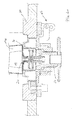
- the reference numeral 10 describes a frusto-conical gas purging plug with an outer metal jacket 12 and a sheet metal bottom 14, which has a central opening 16.
- a refractory ceramic body 10k having a porous portion 10p, through which a gas can be transported in the direction of arrow G from the lower, cold end 10n of the gas purging plug 10 to its upper (not shown) hot end 10o.
- a gas connection piece 20 for the gas purging plug 10 extends around the opening 16.
- the gas connection piece 20 with axial gas channel 26 extends downwards from the opening 16 in the illustrated installation position.
- the gas connection piece 20 has a first end 20.1 at a distance to the gas purging element 10 and a second end 20.2 adjacent to the gas purging element 10.
- the second portion 20.2 is welded to the metal bottom 14 (weld 22).
- the gas connection piece 20 has a cross-sectional change on the inside, the part facing the gas purging plug 10 having a larger cross-section.
- a body 24 is loosely arranged. Without gas pressure it rests on a shoulder of the described cross-sectional reduction of the gas channel 26. Under gas pressure, the body 24 lifts off the shoulder and moves toward the gas purging plug 10.
- a locking pin 28 disposed above the body 24 prevents the body 24 from blocking the opening 16.
- the gas channel 26 widens conically downwards and outwards.
- a second end 30.2 of a Gaszi211 line 30 is inserted gas-tight.
- This end 30.2 is designed according to a truncated cone (nozzle-like) and its tapered end is up.
- the end 20.1 forms the can, the end 30.2 the plug of the connector.
- the gas supply line 30 has a shoulder 33 slightly below the first end 20. 1 of the gas connection piece 20.
- a shoulder 32 abuts an annular inner shoulder 42 of a securing element 40, which is also tubular.
- the securing element 40 has, in the area above the shoulder 42, an internal thread 42i which is screwed onto a corresponding external thread 20.1a of the likewise externally cylindrical first end 20.1 of the gas connecting piece 20.
- the securing element 40 extends tubular down to a radially outwardly extending wheel 44 for locking.
- connection connection of gas connection piece 20 and gas supply line 30 is formed with axially nested sections 20.1, 30.2, wherein the connector is secured via the securing element 40 against loosening.
- FIG. 1 shows the mounting position, in which the mounting device engages over the gas connection piece 20 and the second end 30.2 of the gas supply line 30 with an annular element 64.
- the annular member 64 is fixed relative to the fixed outer shell 50 by means of a handle 66 in the position shown.
- the element 64 rests against a sleeve 68, which surrounds the second end 20. 2 of the gas connecting piece 20.
- the sleeve 68 is part of the refractory lining below the Gas Whyiatas 10.
- the first end 20.1 of the gas connection piece 20 protrudes downwards over the sleeve 68 before.
- the assembly is simple because the mounting device 60 can be pivoted to the position described before the gas supply line 30 is fitted and secured to the gas connection piece 20. Before the gas-tight connection of the parts 20,30 of the gas purging plug 10 is securely positioned.
- the gas connection piece 20 of the connection connection is precisely adjusted, so that the plug connection with the gas supply line 30 can be very simple, accurate and quick.
- the length of the gas supply line 30 is arbitrary.
- the gas supply line 30 may also consist of several sections, which in turn can be connected by plug connection (or otherwise) gas-tight with each other.
Landscapes
- Engineering & Computer Science (AREA)
- Chemical & Material Sciences (AREA)
- Organic Chemistry (AREA)
- Materials Engineering (AREA)
- Metallurgy (AREA)
- Mechanical Engineering (AREA)
- Manufacturing & Machinery (AREA)
- General Engineering & Computer Science (AREA)
- Treatment Of Steel In Its Molten State (AREA)
- Furnace Charging Or Discharging (AREA)
- Carbon Steel Or Casting Steel Manufacturing (AREA)
- Manufacture And Refinement Of Metals (AREA)
- Waste-Gas Treatment And Other Accessory Devices For Furnaces (AREA)
Priority Applications (22)
| Application Number | Priority Date | Filing Date | Title |
|---|---|---|---|
| EP16181865.3A EP3106813A1 (fr) | 2012-08-27 | 2012-08-27 | Élément de lavage de gaz avec conduite d'alimentation en gaz correspondante |
| HUE12181902A HUE029621T2 (en) | 2012-08-27 | 2012-08-27 | Gas inlet element with associated gas supply line |
| PL12181902.3T PL2703761T3 (pl) | 2012-08-27 | 2012-08-27 | Element do przepłukiwania gazem z należącym do niego przewodem doprowadzającym gaz |
| ES12181902.3T ES2592174T3 (es) | 2012-08-27 | 2012-08-27 | Elemento de purga de gas con conducto de suministro de gas correspondiente |
| EP12181902.3A EP2703761B1 (fr) | 2012-08-27 | 2012-08-27 | Élément de lavage de gaz avec conduite d'alimentation en gaz correspondante |
| UAA201413414A UA111663C2 (uk) | 2012-08-27 | 2013-07-08 | Газопродувний елемент і співвіднесений газопідвідний трубопровід |
| TW102125226A TWI558485B (zh) | 2012-08-27 | 2013-07-15 | 氣體沖灌元件及對應的氣體供應線 |
| KR1020147035060A KR101687091B1 (ko) | 2012-08-27 | 2013-08-07 | 가스 정화 요소 및 관련 가스 공급 라인 |
| PE2014002454A PE20150152A1 (es) | 2012-08-27 | 2013-08-07 | Elemento de purga de gas y linea de alimentacion de gas asociada |
| CN201380036101.8A CN104412058B (zh) | 2012-08-27 | 2013-08-07 | 吹气元件和相关的气体输送管路 |
| EA201401263A EA029105B1 (ru) | 2012-08-27 | 2013-08-07 | Газопродувочное устройство для металлургических применений |
| MX2014012134A MX362688B (es) | 2012-08-27 | 2013-08-07 | Elemento de purga de gas y línea de alimentación de gas asociada. |
| JP2015527843A JP5982574B2 (ja) | 2012-08-27 | 2013-08-07 | ガスパージ要素および対応するガス供給ライン |
| PCT/EP2013/066531 WO2014032923A2 (fr) | 2012-08-27 | 2013-08-07 | Élément de barbotage et conduite d'alimentation en gaz correspondante |
| US14/411,865 US9683272B2 (en) | 2012-08-27 | 2013-08-07 | Gas purging element and associated gas feed line |
| CA2876461A CA2876461C (fr) | 2012-08-27 | 2013-08-07 | Element de purge de gaz et conduite d'amenee de gaz correspondante |
| BR112015000090-8A BR112015000090B1 (pt) | 2012-08-27 | 2013-08-07 | dispositivo de purga de gás |
| IL236502A IL236502B (en) | 2012-08-27 | 2014-12-28 | Gas purification agent and compatible gas supply pipe |
| CL2014003639A CL2014003639A1 (es) | 2012-08-27 | 2014-12-31 | Elemento de purga de gas para aplicaciones metalurgicas con las siguientes caracteristicas, con un cuerpo de ceramica a prueba de fuego con un primer extremo y un segundo extremo; un tubo de suministro de gas para un elemento de purga de gas. |
| SA515360061A SA515360061B1 (ar) | 2012-08-27 | 2015-02-23 | عنصر تطهير غـاز وخط تغذية غـاز ذي صلة |
| ZA2015/01967A ZA201501967B (en) | 2012-08-27 | 2015-03-23 | Gas purging element and associated gas feed line |
| US15/604,151 US20170327914A1 (en) | 2012-08-27 | 2017-05-24 | Gas purging element and corresponding gas supply line |
Applications Claiming Priority (1)
| Application Number | Priority Date | Filing Date | Title |
|---|---|---|---|
| EP12181902.3A EP2703761B1 (fr) | 2012-08-27 | 2012-08-27 | Élément de lavage de gaz avec conduite d'alimentation en gaz correspondante |
Related Child Applications (1)
| Application Number | Title | Priority Date | Filing Date |
|---|---|---|---|
| EP16181865.3A Division EP3106813A1 (fr) | 2012-08-27 | 2012-08-27 | Élément de lavage de gaz avec conduite d'alimentation en gaz correspondante |
Publications (2)
| Publication Number | Publication Date |
|---|---|
| EP2703761A1 true EP2703761A1 (fr) | 2014-03-05 |
| EP2703761B1 EP2703761B1 (fr) | 2016-08-17 |
Family
ID=46799073
Family Applications (2)
| Application Number | Title | Priority Date | Filing Date |
|---|---|---|---|
| EP12181902.3A Active EP2703761B1 (fr) | 2012-08-27 | 2012-08-27 | Élément de lavage de gaz avec conduite d'alimentation en gaz correspondante |
| EP16181865.3A Withdrawn EP3106813A1 (fr) | 2012-08-27 | 2012-08-27 | Élément de lavage de gaz avec conduite d'alimentation en gaz correspondante |
Family Applications After (1)
| Application Number | Title | Priority Date | Filing Date |
|---|---|---|---|
| EP16181865.3A Withdrawn EP3106813A1 (fr) | 2012-08-27 | 2012-08-27 | Élément de lavage de gaz avec conduite d'alimentation en gaz correspondante |
Country Status (20)
| Country | Link |
|---|---|
| US (2) | US9683272B2 (fr) |
| EP (2) | EP2703761B1 (fr) |
| JP (1) | JP5982574B2 (fr) |
| KR (1) | KR101687091B1 (fr) |
| CN (1) | CN104412058B (fr) |
| BR (1) | BR112015000090B1 (fr) |
| CA (1) | CA2876461C (fr) |
| CL (1) | CL2014003639A1 (fr) |
| EA (1) | EA029105B1 (fr) |
| ES (1) | ES2592174T3 (fr) |
| HU (1) | HUE029621T2 (fr) |
| IL (1) | IL236502B (fr) |
| MX (1) | MX362688B (fr) |
| PE (1) | PE20150152A1 (fr) |
| PL (1) | PL2703761T3 (fr) |
| SA (1) | SA515360061B1 (fr) |
| TW (1) | TWI558485B (fr) |
| UA (1) | UA111663C2 (fr) |
| WO (1) | WO2014032923A2 (fr) |
| ZA (1) | ZA201501967B (fr) |
Cited By (1)
| Publication number | Priority date | Publication date | Assignee | Title |
|---|---|---|---|---|
| CN109777921A (zh) * | 2017-11-14 | 2019-05-21 | 党祎贤 | 一种钢包吹氩自动对接机构 |
Families Citing this family (3)
| Publication number | Priority date | Publication date | Assignee | Title |
|---|---|---|---|---|
| HUE029621T2 (en) * | 2012-08-27 | 2017-03-28 | Refractory Intellectual Property Gmbh & Co Kg | Gas inlet element with associated gas supply line |
| WO2019065247A1 (fr) * | 2017-09-28 | 2019-04-04 | 黒崎播磨株式会社 | Structure de douille de trou d'introduction de gaz |
| US11408040B2 (en) | 2018-01-29 | 2022-08-09 | Refractory Intellectual Property Gmbh & Co. Kg | Gas purging plug, gas purging system, method for characterization of a gas purging plug and method for purging a metal melt |
Citations (8)
| Publication number | Priority date | Publication date | Assignee | Title |
|---|---|---|---|---|
| US3834685A (en) * | 1973-09-24 | 1974-09-10 | Allegheny Ludlum Ind Inc | Apparatus for injecting fluids into molten metals |
| AT365958B (de) * | 1980-06-30 | 1982-02-25 | Voest Alpine Ag | Metallurgisches gefaess |
| EP0148337A1 (fr) | 1983-11-17 | 1985-07-17 | Radex Deutschland Aktiengesellschaft für feuerfeste Erzeugnisse | Brique pour lavage au gaz pour récipients métallurgiques |
| EP0234852A1 (fr) * | 1986-02-20 | 1987-09-02 | Injectall Limited | Injection de substances dans des liquides à haute température |
| DE3833502C2 (fr) | 1988-10-01 | 1990-10-04 | Didier-Werke Ag, 6200 Wiesbaden, De | |
| US5112029A (en) * | 1991-07-22 | 1992-05-12 | Instituo Mexicano De Investigaciones Siderurgicas | Quick fluid injection assembly replacement in metallurgical reacters |
| WO2005107979A1 (fr) * | 2004-05-05 | 2005-11-17 | Stefan Munding | Dispositif de rinçage au gaz |
| WO2011118477A1 (fr) * | 2010-03-23 | 2011-09-29 | 黒崎播磨株式会社 | Structure d'installation d'un bouchon d'injection de gaz |
Family Cites Families (12)
| Publication number | Priority date | Publication date | Assignee | Title |
|---|---|---|---|---|
| FR2451945A1 (fr) * | 1979-03-19 | 1980-10-17 | Est Aciers Fins | Tuyere de brassage de bain de metal liquide |
| US4632367A (en) * | 1984-10-19 | 1986-12-30 | Labate Michael D | Device for introducing gas into molten metal |
| US4725047A (en) * | 1985-08-26 | 1988-02-16 | Labate M D | Device for introducing gas into molten metal |
| DE3833504A1 (de) * | 1988-10-01 | 1990-04-05 | Didier Werke Ag | Gasspueleinrichtung |
| CA2014999C (fr) * | 1989-04-24 | 1999-09-07 | Kenneth William Bates | Injecteur de gaz |
| DE4029024C2 (de) * | 1990-09-13 | 1999-10-28 | Beda Oxygentech Armatur | Spülanschlußkupplung |
| DE4121329C2 (de) * | 1991-06-28 | 1995-09-07 | Veitsch Radex Ag | Gasspülstein |
| DE19948848C1 (de) * | 1999-10-08 | 2000-07-13 | Dolomitwerke Gmbh | Gasspülstein für metallurgische Gefäße |
| KR200417535Y1 (ko) * | 2006-03-21 | 2006-05-30 | 조선내화 주식회사 | 래들용 버블링플러그 고정장치 |
| CN201221636Y (zh) * | 2008-06-05 | 2009-04-15 | 钟伯华 | 瓦斯阀座 |
| JP2010189687A (ja) * | 2009-02-17 | 2010-09-02 | Tokyo Yogyo Co Ltd | ガス吹き込みプラグ |
| HUE029621T2 (en) * | 2012-08-27 | 2017-03-28 | Refractory Intellectual Property Gmbh & Co Kg | Gas inlet element with associated gas supply line |
-
2012
- 2012-08-27 HU HUE12181902A patent/HUE029621T2/en unknown
- 2012-08-27 PL PL12181902.3T patent/PL2703761T3/pl unknown
- 2012-08-27 EP EP12181902.3A patent/EP2703761B1/fr active Active
- 2012-08-27 EP EP16181865.3A patent/EP3106813A1/fr not_active Withdrawn
- 2012-08-27 ES ES12181902.3T patent/ES2592174T3/es active Active
-
2013
- 2013-07-08 UA UAA201413414A patent/UA111663C2/uk unknown
- 2013-07-15 TW TW102125226A patent/TWI558485B/zh active
- 2013-08-07 CA CA2876461A patent/CA2876461C/fr active Active
- 2013-08-07 BR BR112015000090-8A patent/BR112015000090B1/pt active IP Right Grant
- 2013-08-07 JP JP2015527843A patent/JP5982574B2/ja not_active Expired - Fee Related
- 2013-08-07 EA EA201401263A patent/EA029105B1/ru not_active IP Right Cessation
- 2013-08-07 US US14/411,865 patent/US9683272B2/en active Active
- 2013-08-07 PE PE2014002454A patent/PE20150152A1/es not_active Application Discontinuation
- 2013-08-07 WO PCT/EP2013/066531 patent/WO2014032923A2/fr not_active Ceased
- 2013-08-07 MX MX2014012134A patent/MX362688B/es active IP Right Grant
- 2013-08-07 KR KR1020147035060A patent/KR101687091B1/ko not_active Expired - Fee Related
- 2013-08-07 CN CN201380036101.8A patent/CN104412058B/zh active Active
-
2014
- 2014-12-28 IL IL236502A patent/IL236502B/en not_active IP Right Cessation
- 2014-12-31 CL CL2014003639A patent/CL2014003639A1/es unknown
-
2015
- 2015-02-23 SA SA515360061A patent/SA515360061B1/ar unknown
- 2015-03-23 ZA ZA2015/01967A patent/ZA201501967B/en unknown
-
2017
- 2017-05-24 US US15/604,151 patent/US20170327914A1/en not_active Abandoned
Patent Citations (8)
| Publication number | Priority date | Publication date | Assignee | Title |
|---|---|---|---|---|
| US3834685A (en) * | 1973-09-24 | 1974-09-10 | Allegheny Ludlum Ind Inc | Apparatus for injecting fluids into molten metals |
| AT365958B (de) * | 1980-06-30 | 1982-02-25 | Voest Alpine Ag | Metallurgisches gefaess |
| EP0148337A1 (fr) | 1983-11-17 | 1985-07-17 | Radex Deutschland Aktiengesellschaft für feuerfeste Erzeugnisse | Brique pour lavage au gaz pour récipients métallurgiques |
| EP0234852A1 (fr) * | 1986-02-20 | 1987-09-02 | Injectall Limited | Injection de substances dans des liquides à haute température |
| DE3833502C2 (fr) | 1988-10-01 | 1990-10-04 | Didier-Werke Ag, 6200 Wiesbaden, De | |
| US5112029A (en) * | 1991-07-22 | 1992-05-12 | Instituo Mexicano De Investigaciones Siderurgicas | Quick fluid injection assembly replacement in metallurgical reacters |
| WO2005107979A1 (fr) * | 2004-05-05 | 2005-11-17 | Stefan Munding | Dispositif de rinçage au gaz |
| WO2011118477A1 (fr) * | 2010-03-23 | 2011-09-29 | 黒崎播磨株式会社 | Structure d'installation d'un bouchon d'injection de gaz |
Cited By (1)
| Publication number | Priority date | Publication date | Assignee | Title |
|---|---|---|---|---|
| CN109777921A (zh) * | 2017-11-14 | 2019-05-21 | 党祎贤 | 一种钢包吹氩自动对接机构 |
Also Published As
| Publication number | Publication date |
|---|---|
| EP2703761B1 (fr) | 2016-08-17 |
| KR101687091B1 (ko) | 2016-12-15 |
| BR112015000090A2 (pt) | 2017-06-27 |
| IL236502B (en) | 2018-03-29 |
| JP5982574B2 (ja) | 2016-08-31 |
| US20150184265A1 (en) | 2015-07-02 |
| ES2592174T3 (es) | 2016-11-28 |
| CA2876461C (fr) | 2017-07-18 |
| CL2014003639A1 (es) | 2015-07-31 |
| SA515360061B1 (ar) | 2017-04-16 |
| EA201401263A1 (ru) | 2015-07-30 |
| WO2014032923A2 (fr) | 2014-03-06 |
| PE20150152A1 (es) | 2015-02-07 |
| CN104412058A (zh) | 2015-03-11 |
| BR112015000090B1 (pt) | 2021-01-19 |
| US20170327914A1 (en) | 2017-11-16 |
| TWI558485B (zh) | 2016-11-21 |
| JP2015531828A (ja) | 2015-11-05 |
| WO2014032923A3 (fr) | 2014-06-26 |
| US9683272B2 (en) | 2017-06-20 |
| HUE029621T2 (en) | 2017-03-28 |
| CN104412058B (zh) | 2016-08-17 |
| IL236502A0 (en) | 2015-02-26 |
| EP3106813A1 (fr) | 2016-12-21 |
| EA029105B1 (ru) | 2018-02-28 |
| UA111663C2 (uk) | 2016-05-25 |
| KR20150030204A (ko) | 2015-03-19 |
| MX2014012134A (es) | 2015-03-05 |
| PL2703761T3 (pl) | 2016-12-30 |
| CA2876461A1 (fr) | 2014-03-06 |
| MX362688B (es) | 2019-02-01 |
| TW201408400A (zh) | 2014-03-01 |
| ZA201501967B (en) | 2016-01-27 |
Similar Documents
| Publication | Publication Date | Title |
|---|---|---|
| EP3379129B1 (fr) | Raccord | |
| WO2006045553A1 (fr) | Raccord enfichable resistant a la traction | |
| EP3526507B1 (fr) | Connecteur, module de connecteur et procédé permettant de produire un connecteur | |
| EP2743582A1 (fr) | Pointe de brûleur et brûleur | |
| EP2703761B1 (fr) | Élément de lavage de gaz avec conduite d'alimentation en gaz correspondante | |
| EP2047110B1 (fr) | Dispositif technique fluidique | |
| EP3173675A1 (fr) | Raccord de tuyau | |
| DE112014000513B4 (de) | Durchflussratensteuervorrichtung | |
| EP2496871B1 (fr) | Système de raccordement, distributeur, système de conduites et système de montage en déport de conduites | |
| EP2743579A1 (fr) | Pointe de brûleur et brûleur | |
| EP2183518B1 (fr) | Coiffe de protection pour un raccord a fiche | |
| EP1745231B1 (fr) | Dispositif d'accouplement d'une bouteille de gaz sous pression | |
| DE202007018625U1 (de) | Schneidbrenner mit einem Brennerkopf, der eine auswechselbare Schneiddüse aufnimmt | |
| EP3467382B1 (fr) | Unité de raccordement de carburant | |
| EP2893992B1 (fr) | Élément de rinçage de gaz et élément de raccord de gaz associé | |
| EP2208676A1 (fr) | Serre-joint | |
| EP1549873B1 (fr) | Element de reception de connecteur enfichable pour fluides | |
| EP2409069B1 (fr) | Dispositif de répartition d'un fluide de lubrification | |
| DE102014217410B4 (de) | Fluidleitende Verbindungsanordnung sowie Klemmring | |
| DE20103054U1 (de) | Gasdurchlass an einem gasführenden Gehäuse | |
| DE102013103534B4 (de) | "Steckverbindungsteil für einen Leitungsverbinder, insbesondere für eine konfektionierte Medienleitung" | |
| WO2018210622A1 (fr) | Dispositif de raccordement | |
| EP1384867A1 (fr) | Dispositif d'étanchéification d'un conduite des gaz d'échappement | |
| DE29618605U1 (de) | Absperrarmatur | |
| DE3702561C2 (fr) |
Legal Events
| Date | Code | Title | Description |
|---|---|---|---|
| 17P | Request for examination filed |
Effective date: 20131011 |
|
| AK | Designated contracting states |
Kind code of ref document: A1 Designated state(s): AL AT BE BG CH CY CZ DE DK EE ES FI FR GB GR HR HU IE IS IT LI LT LU LV MC MK MT NL NO PL PT RO RS SE SI SK SM TR |
|
| AX | Request for extension of the european patent |
Extension state: BA ME |
|
| PUAI | Public reference made under article 153(3) epc to a published international application that has entered the european phase |
Free format text: ORIGINAL CODE: 0009012 |
|
| 17Q | First examination report despatched |
Effective date: 20141211 |
|
| GRAP | Despatch of communication of intention to grant a patent |
Free format text: ORIGINAL CODE: EPIDOSNIGR1 |
|
| INTG | Intention to grant announced |
Effective date: 20160527 |
|
| GRAS | Grant fee paid |
Free format text: ORIGINAL CODE: EPIDOSNIGR3 |
|
| GRAA | (expected) grant |
Free format text: ORIGINAL CODE: 0009210 |
|
| AK | Designated contracting states |
Kind code of ref document: B1 Designated state(s): AL AT BE BG CH CY CZ DE DK EE ES FI FR GB GR HR HU IE IS IT LI LT LU LV MC MK MT NL NO PL PT RO RS SE SI SK SM TR |
|
| REG | Reference to a national code |
Ref country code: GB Ref legal event code: FG4D Free format text: NOT ENGLISH |
|
| REG | Reference to a national code |
Ref country code: CH Ref legal event code: EP |
|
| REG | Reference to a national code |
Ref country code: IE Ref legal event code: FG4D Free format text: LANGUAGE OF EP DOCUMENT: GERMAN |
|
| REG | Reference to a national code |
Ref country code: AT Ref legal event code: REF Ref document number: 821510 Country of ref document: AT Kind code of ref document: T Effective date: 20160915 |
|
| REG | Reference to a national code |
Ref country code: SE Ref legal event code: TRGR |
|
| REG | Reference to a national code |
Ref country code: NL Ref legal event code: FP Ref country code: RO Ref legal event code: EPE |
|
| REG | Reference to a national code |
Ref country code: DE Ref legal event code: R096 Ref document number: 502012007954 Country of ref document: DE Ref country code: FR Ref legal event code: PLFP Year of fee payment: 5 |
|
| REG | Reference to a national code |
Ref country code: ES Ref legal event code: FG2A Ref document number: 2592174 Country of ref document: ES Kind code of ref document: T3 Effective date: 20161128 |
|
| REG | Reference to a national code |
Ref country code: LT Ref legal event code: MG4D |
|
| PG25 | Lapsed in a contracting state [announced via postgrant information from national office to epo] |
Ref country code: LT Free format text: LAPSE BECAUSE OF FAILURE TO SUBMIT A TRANSLATION OF THE DESCRIPTION OR TO PAY THE FEE WITHIN THE PRESCRIBED TIME-LIMIT Effective date: 20160817 Ref country code: RS Free format text: LAPSE BECAUSE OF FAILURE TO SUBMIT A TRANSLATION OF THE DESCRIPTION OR TO PAY THE FEE WITHIN THE PRESCRIBED TIME-LIMIT Effective date: 20160817 Ref country code: HR Free format text: LAPSE BECAUSE OF FAILURE TO SUBMIT A TRANSLATION OF THE DESCRIPTION OR TO PAY THE FEE WITHIN THE PRESCRIBED TIME-LIMIT Effective date: 20160817 Ref country code: NO Free format text: LAPSE BECAUSE OF FAILURE TO SUBMIT A TRANSLATION OF THE DESCRIPTION OR TO PAY THE FEE WITHIN THE PRESCRIBED TIME-LIMIT Effective date: 20161117 |
|
| REG | Reference to a national code |
Ref country code: SK Ref legal event code: T3 Ref document number: E 22274 Country of ref document: SK |
|
| PG25 | Lapsed in a contracting state [announced via postgrant information from national office to epo] |
Ref country code: GR Free format text: LAPSE BECAUSE OF FAILURE TO SUBMIT A TRANSLATION OF THE DESCRIPTION OR TO PAY THE FEE WITHIN THE PRESCRIBED TIME-LIMIT Effective date: 20161118 Ref country code: PT Free format text: LAPSE BECAUSE OF FAILURE TO SUBMIT A TRANSLATION OF THE DESCRIPTION OR TO PAY THE FEE WITHIN THE PRESCRIBED TIME-LIMIT Effective date: 20161219 Ref country code: LV Free format text: LAPSE BECAUSE OF FAILURE TO SUBMIT A TRANSLATION OF THE DESCRIPTION OR TO PAY THE FEE WITHIN THE PRESCRIBED TIME-LIMIT Effective date: 20160817 |
|
| REG | Reference to a national code |
Ref country code: HU Ref legal event code: AG4A Ref document number: E029621 Country of ref document: HU |
|
| PG25 | Lapsed in a contracting state [announced via postgrant information from national office to epo] |
Ref country code: EE Free format text: LAPSE BECAUSE OF FAILURE TO SUBMIT A TRANSLATION OF THE DESCRIPTION OR TO PAY THE FEE WITHIN THE PRESCRIBED TIME-LIMIT Effective date: 20160817 |
|
| REG | Reference to a national code |
Ref country code: DE Ref legal event code: R097 Ref document number: 502012007954 Country of ref document: DE |
|
| PG25 | Lapsed in a contracting state [announced via postgrant information from national office to epo] |
Ref country code: DK Free format text: LAPSE BECAUSE OF FAILURE TO SUBMIT A TRANSLATION OF THE DESCRIPTION OR TO PAY THE FEE WITHIN THE PRESCRIBED TIME-LIMIT Effective date: 20160817 Ref country code: SM Free format text: LAPSE BECAUSE OF FAILURE TO SUBMIT A TRANSLATION OF THE DESCRIPTION OR TO PAY THE FEE WITHIN THE PRESCRIBED TIME-LIMIT Effective date: 20160817 Ref country code: BG Free format text: LAPSE BECAUSE OF FAILURE TO SUBMIT A TRANSLATION OF THE DESCRIPTION OR TO PAY THE FEE WITHIN THE PRESCRIBED TIME-LIMIT Effective date: 20161117 |
|
| REG | Reference to a national code |
Ref country code: IE Ref legal event code: MM4A |
|
| PLBE | No opposition filed within time limit |
Free format text: ORIGINAL CODE: 0009261 |
|
| STAA | Information on the status of an ep patent application or granted ep patent |
Free format text: STATUS: NO OPPOSITION FILED WITHIN TIME LIMIT |
|
| PG25 | Lapsed in a contracting state [announced via postgrant information from national office to epo] |
Ref country code: MC Free format text: LAPSE BECAUSE OF FAILURE TO SUBMIT A TRANSLATION OF THE DESCRIPTION OR TO PAY THE FEE WITHIN THE PRESCRIBED TIME-LIMIT Effective date: 20160817 |
|
| 26N | No opposition filed |
Effective date: 20170518 |
|
| PG25 | Lapsed in a contracting state [announced via postgrant information from national office to epo] |
Ref country code: IE Free format text: LAPSE BECAUSE OF NON-PAYMENT OF DUE FEES Effective date: 20160827 |
|
| REG | Reference to a national code |
Ref country code: FR Ref legal event code: PLFP Year of fee payment: 6 |
|
| PG25 | Lapsed in a contracting state [announced via postgrant information from national office to epo] |
Ref country code: SI Free format text: LAPSE BECAUSE OF FAILURE TO SUBMIT A TRANSLATION OF THE DESCRIPTION OR TO PAY THE FEE WITHIN THE PRESCRIBED TIME-LIMIT Effective date: 20160817 |
|
| PGFP | Annual fee paid to national office [announced via postgrant information from national office to epo] |
Ref country code: GB Payment date: 20170727 Year of fee payment: 14 |
|
| PGFP | Annual fee paid to national office [announced via postgrant information from national office to epo] |
Ref country code: SK Payment date: 20170818 Year of fee payment: 6 |
|
| PG25 | Lapsed in a contracting state [announced via postgrant information from national office to epo] |
Ref country code: CY Free format text: LAPSE BECAUSE OF FAILURE TO SUBMIT A TRANSLATION OF THE DESCRIPTION OR TO PAY THE FEE WITHIN THE PRESCRIBED TIME-LIMIT Effective date: 20160817 |
|
| PG25 | Lapsed in a contracting state [announced via postgrant information from national office to epo] |
Ref country code: MT Free format text: LAPSE BECAUSE OF FAILURE TO SUBMIT A TRANSLATION OF THE DESCRIPTION OR TO PAY THE FEE WITHIN THE PRESCRIBED TIME-LIMIT Effective date: 20160817 Ref country code: MK Free format text: LAPSE BECAUSE OF FAILURE TO SUBMIT A TRANSLATION OF THE DESCRIPTION OR TO PAY THE FEE WITHIN THE PRESCRIBED TIME-LIMIT Effective date: 20160817 Ref country code: IS Free format text: LAPSE BECAUSE OF FAILURE TO SUBMIT A TRANSLATION OF THE DESCRIPTION OR TO PAY THE FEE WITHIN THE PRESCRIBED TIME-LIMIT Effective date: 20160817 |
|
| REG | Reference to a national code |
Ref country code: FR Ref legal event code: PLFP Year of fee payment: 7 |
|
| PG25 | Lapsed in a contracting state [announced via postgrant information from national office to epo] |
Ref country code: AL Free format text: LAPSE BECAUSE OF FAILURE TO SUBMIT A TRANSLATION OF THE DESCRIPTION OR TO PAY THE FEE WITHIN THE PRESCRIBED TIME-LIMIT Effective date: 20160817 |
|
| REG | Reference to a national code |
Ref country code: NL Ref legal event code: MM Effective date: 20180901 |
|
| REG | Reference to a national code |
Ref country code: SK Ref legal event code: MM4A Ref document number: E 22274 Country of ref document: SK Effective date: 20180827 |
|
| PG25 | Lapsed in a contracting state [announced via postgrant information from national office to epo] |
Ref country code: SK Free format text: LAPSE BECAUSE OF NON-PAYMENT OF DUE FEES Effective date: 20180827 |
|
| PG25 | Lapsed in a contracting state [announced via postgrant information from national office to epo] |
Ref country code: NL Free format text: LAPSE BECAUSE OF NON-PAYMENT OF DUE FEES Effective date: 20180901 |
|
| PGFP | Annual fee paid to national office [announced via postgrant information from national office to epo] |
Ref country code: HU Payment date: 20210821 Year of fee payment: 10 |
|
| PG25 | Lapsed in a contracting state [announced via postgrant information from national office to epo] |
Ref country code: HU Free format text: LAPSE BECAUSE OF NON-PAYMENT OF DUE FEES Effective date: 20220828 |
|
| PGFP | Annual fee paid to national office [announced via postgrant information from national office to epo] |
Ref country code: LU Payment date: 20250822 Year of fee payment: 14 |
|
| PGFP | Annual fee paid to national office [announced via postgrant information from national office to epo] |
Ref country code: ES Payment date: 20250926 Year of fee payment: 14 Ref country code: FI Payment date: 20250822 Year of fee payment: 14 |
|
| PGFP | Annual fee paid to national office [announced via postgrant information from national office to epo] |
Ref country code: DE Payment date: 20250820 Year of fee payment: 14 |
|
| PGFP | Annual fee paid to national office [announced via postgrant information from national office to epo] |
Ref country code: IT Payment date: 20250825 Year of fee payment: 14 Ref country code: TR Payment date: 20250819 Year of fee payment: 14 Ref country code: PL Payment date: 20250818 Year of fee payment: 14 |
|
| PGFP | Annual fee paid to national office [announced via postgrant information from national office to epo] |
Ref country code: BE Payment date: 20250820 Year of fee payment: 14 Ref country code: GB Payment date: 20250820 Year of fee payment: 14 |
|
| PGFP | Annual fee paid to national office [announced via postgrant information from national office to epo] |
Ref country code: FR Payment date: 20250829 Year of fee payment: 14 Ref country code: AT Payment date: 20250821 Year of fee payment: 14 |
|
| PGFP | Annual fee paid to national office [announced via postgrant information from national office to epo] |
Ref country code: CH Payment date: 20250901 Year of fee payment: 14 Ref country code: SE Payment date: 20250820 Year of fee payment: 14 |
|
| PGFP | Annual fee paid to national office [announced via postgrant information from national office to epo] |
Ref country code: CZ Payment date: 20250818 Year of fee payment: 14 |
|
| PGFP | Annual fee paid to national office [announced via postgrant information from national office to epo] |
Ref country code: RO Payment date: 20250818 Year of fee payment: 14 |