WO2019065247A1 - Structure de douille de trou d'introduction de gaz - Google Patents
Structure de douille de trou d'introduction de gaz Download PDFInfo
- Publication number
- WO2019065247A1 WO2019065247A1 PCT/JP2018/033836 JP2018033836W WO2019065247A1 WO 2019065247 A1 WO2019065247 A1 WO 2019065247A1 JP 2018033836 W JP2018033836 W JP 2018033836W WO 2019065247 A1 WO2019065247 A1 WO 2019065247A1
- Authority
- WO
- WIPO (PCT)
- Prior art keywords
- socket
- gas introduction
- introduction hole
- refractory
- conductive material
- Prior art date
- Legal status (The legal status is an assumption and is not a legal conclusion. Google has not performed a legal analysis and makes no representation as to the accuracy of the status listed.)
- Ceased
Links
Images






Classifications
-
- B—PERFORMING OPERATIONS; TRANSPORTING
- B22—CASTING; POWDER METALLURGY
- B22D—CASTING OF METALS; CASTING OF OTHER SUBSTANCES BY THE SAME PROCESSES OR DEVICES
- B22D1/00—Treatment of fused masses in the ladle or the supply runners before casting
- B22D1/002—Treatment with gases
- B22D1/005—Injection assemblies therefor
-
- B—PERFORMING OPERATIONS; TRANSPORTING
- B22—CASTING; POWDER METALLURGY
- B22D—CASTING OF METALS; CASTING OF OTHER SUBSTANCES BY THE SAME PROCESSES OR DEVICES
- B22D11/00—Continuous casting of metals, i.e. casting in indefinite lengths
- B22D11/10—Supplying or treating molten metal
- B22D11/11—Treating the molten metal
- B22D11/116—Refining the metal
- B22D11/117—Refining the metal by treating with gases
-
- B—PERFORMING OPERATIONS; TRANSPORTING
- B22—CASTING; POWDER METALLURGY
- B22D—CASTING OF METALS; CASTING OF OTHER SUBSTANCES BY THE SAME PROCESSES OR DEVICES
- B22D41/00—Casting melt-holding vessels, e.g. ladles, tundishes, cups or the like
- B22D41/50—Pouring-nozzles
- B22D41/58—Pouring-nozzles with gas injecting means
-
- C—CHEMISTRY; METALLURGY
- C21—METALLURGY OF IRON
- C21C—PROCESSING OF PIG-IRON, e.g. REFINING, MANUFACTURE OF WROUGHT-IRON OR STEEL; TREATMENT IN MOLTEN STATE OF FERROUS ALLOYS
- C21C5/00—Manufacture of carbon-steel, e.g. plain mild steel, medium carbon steel or cast steel or stainless steel
- C21C5/28—Manufacture of steel in the converter
- C21C5/42—Constructional features of converters
- C21C5/46—Details or accessories
- C21C5/48—Bottoms or tuyéres of converters
-
- C—CHEMISTRY; METALLURGY
- C21—METALLURGY OF IRON
- C21C—PROCESSING OF PIG-IRON, e.g. REFINING, MANUFACTURE OF WROUGHT-IRON OR STEEL; TREATMENT IN MOLTEN STATE OF FERROUS ALLOYS
- C21C7/00—Treating molten ferrous alloys, e.g. steel, not covered by groups C21C1/00 - C21C5/00
- C21C7/04—Removing impurities by adding a treating agent
- C21C7/072—Treatment with gases
Definitions
- the present invention relates to the structure of a gas introduction hole socket portion such as a nozzle or a plug made of a refractory having a function of blowing a gas into a molten metal or a function of blowing out a gas to a specific part.
- Nozzles and plugs in which spaces such as slits for gas flow and storage, pressure equalization, etc., porous refractories etc. (hereinafter, also simply referred to as "gas pool”) are disposed inside the refractory constituting the main body Etc. (hereinafter, also referred to simply as “main body” or “refractory main body”), in order to introduce a gas into the gas pool, install a socket in the refractory main body or a metal case surrounding the main body. It is common to connect a gas inlet pipe to its socket.
- Patent Document 1 is for gas-casting continuous casting in which a socket having a flange or a step portion on the rear end side to which a gas introduction pipe is connected is attached to a socket hole via a sealing material.
- a refractory socket mounting structure we propose a refractory socket mounting structure.
- patent document 2 in order to eliminate the bad influence by welding with a metal reinforcement board and a socket especially, and eliminate a leak at the time of gas introduction, it is in the upper surface position of the socket attachment hole of the casting nozzle of a metal reinforcement board.
- a method is shown in which a socket and a metal reinforcing plate are attached to a socket mounting hole provided on the side surface of a casting nozzle by providing a through hole and injecting a sealing material from the through hole.
- the second support element (9b) inserted into the cylindrical hole sandwiches the gasket (14) together with the first support element (13), and the rod (9a) compresses the gasket.
- the "supporting element” corresponding to a weir is referred to as the tip end side of the "rod (9a)” corresponding to the socket, that is, the inner side of the main body ("second supporting element (9b)") ("First support element (13)") and by compressing the gasket (14) sandwiched between the crucibles, the gasket extends between the refractory body at the radially extending portion of the socket It is intended to prevent gas leaks by bringing them into close contact.
- Patent Document 1 and Patent Document 2 the gas leak can not be prevented by the seal material of the socket outer peripheral part (for example, the reference numeral 52 in the drawing of Patent Document 1 or the socket outer peripheral part in the drawing 8 of Patent Documents 1 and 2). That is clear also from these patent documents themselves.
- the sealing material instead of the sealing material installed on the outer peripheral surface of the socket, the sealing material is disposed between the refractory body and the weir or step portion installed on the socket rear end side, ie near the outermost periphery of the main body. We try to prevent gas leak by sealing material.
- the structures, methods, and the like of Patent Documents 1 and 2 are applied to a nozzle or the like, gas leak can not be sufficiently prevented.
- the gasket compressed by sandwiching in the axial direction of the socket extends in the radial direction so as to closely contact the refractory main body to prevent gas leak.
- a socket outer peripheral surface only, and with such a gasket contact to convert the compressed force in the axial direction of the socket in the radial direction of the socket, sufficient adhesion can not be obtained. Since there is no sealing material between each of the two crucibles and the refractory body, gas leak can not be sufficiently prevented.
- the problem to be solved by the present invention is to prevent the gas leak in the gas introduction hole socket portion.
- the present invention provides a socket structure for eliminating these causes. That is, the gist of the present invention is the structure of the following gas introduction hole socket portion 1 to 9. 1 A structure of a gas introduction hole socket portion including a socket for connecting a gas supply pipe to a gas introduction hole inside the refractory, A metal plate surrounding a part or all of the refractory body is provided around an end portion of the gas introduction hole on the refractory body external direction side (hereinafter simply referred to as "outside") of the gas introduction hole, The socket is provided with a weir between the outer end and the refractory body inner side (hereinafter simply referred to as "inner") end, The surface on the inner end side of the crucible is adhered to the refractory body via a sealing material, The surface on the outer end side of the crucible is the layer via a low thermal conductive material having a thermal conductivity of 40 (W / (m ⁇ K)) or less at room temperature (hereinafter referred to as “low thermal
- the surface of the inner end portion of the crucible between the outer end portion and the inner end portion and the surface of the refractory body in contact with the surface via the sealing material are directed inward with respect to the central axis of the gas introduction hole
- the structure of the gas introduction hole socket portion according to any one of the items 1 to 5, which is conical with an angle of more than 0 degrees and less than 90 degrees in the outward direction of the gas introduction hole starting from.
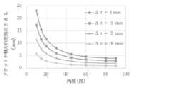
- the thickness L (mm) of the low thermal conductive material layer satisfying the equation 1 is the angle ⁇ (degrees) of the surface of the inner crucible of the socket in contact with the refractory body through the seal material and the wedge
- the variation length ⁇ L (mm) in the axial direction of the socket determined in accordance with the variation length ⁇ t (mm) in the direction perpendicular to the surface of the sealing material between the refractory on the inner end side of the
- the seal that most directly affects the gas leak behavior is installed at a position far from the outer periphery of the main body, that is, at the inner side of the refractory main body.
- a weir is placed on the inner end side of the socket as far as possible between the outer end and the inner end of the socket, and the seal material is installed between the refractory end of the inner end face of the weir . That is, the seal function is not substantially imparted or reinforced between the metal plate around the outer periphery of the refractory main body which is easily deformed (hereinafter, also referred to as “main body outer peripheral side”).
- the crucible is inside the main body, even if heat is received to some extent from the inner side (hereinafter also referred to as “the inner side”) or the outer side (hereinafter referred to as “the outer circumferential side”) As it expands in the direction, uneven deformation is less likely to occur, and it becomes difficult to form a gap on the surface where the weir and the seal material make contact, and there is also an effect of enhancing the sealability in the radial direction and firmly fixing the weir. At the same time, local heat reception of the sealing material or partial deterioration due to the local heat reception is less likely to occur.
- the seal portion is on the inner side of the main body far from the outer peripheral surface of the main body. Since it has an area and is firmly fixed, peeling of the seal portion due to an external force such as a moment applied to the socket does not easily occur.
- the surface on the outer end side of the crucible faces the metal plate on the outer peripheral side of the main body through the layer of low thermal conductivity material or another ridge installed on the outer peripheral side end of the main body from the outer side of the main body Minimize the heat conduction to the weir. Thereby, the non-uniform deformation of the buttocks can be further suppressed.
- local high temperature due to external high temperature or non-uniform atmosphere environment such as being exposed to temperature exceeding 100 ° C especially in welding operation and drying process after socket installation, especially sudden, non-uniform insulation material arrangement environment, etc. Even if a condition or the like occurs, it is possible to suppress the action of heat transfer such as a rapid temperature rise of the seal portion where the uneven or uneven moisture in the inside of the buttocks is rapidly vaporized.
- the sealability between the socket and the refractory body is enhanced, it is less necessary to secure strict sealability with the metal case on the outer peripheral side of the refractory body via the low thermal conductivity material layer. Therefore, it is less necessary to weld the entire circumference around the socket (or the crucible on the outer peripheral side of the refractory main body) to the metal case on the outer peripheral side of the refractory main body.
- the minimum welding such that the socket (or the crucible on the outer peripheral side of the refractory main body) can be fixed to the metal case on the outer peripheral side of the refractory main body and does not even cause deformation or deviation make it possible to As a result, the thermal load on the seal portion can be further reduced, and deformation of the socket (or the crucible on the outer periphery of the refractory body) and the metal case on the outer periphery of the refractory body can be reduced. It can be improved.
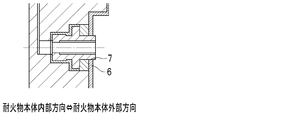
- FIG. 1 It is an image figure showing an example of the structure of the gas introduction hole socket part of the present invention which is the structure of a seal part perpendicular to socket axial direction, and showing the section of the field which passes a gas introduction hole central axis.
- A is an example in which the inner ridge portion is installed near the outer periphery of the refractory main body and the inner end of the refractory main body of the socket is present in the refractory main body
- (b) (C) installed near the outer periphery and extending the inner end of the refractory body of the socket to the gas pool portion in the refractory body has the same structure as (b) in An example where the length of the low thermal conductive material layer is further extended by placing the part near the inner side of the refractory body
- (A) is an example in which the inner ridge portion is installed near the outer periphery of the refractory main body, and the inner end of the refractory main body of the socket is present in the refractory main body
- (b) An example in which the low thermal conductive material layer is set longer than the case of (a) and the length of the low thermal conductive material layer is extended, and the inner end of the refractory body of the socket is extended to the gas pool portion in the refractory body
- (A) is an example in which the inner ridge portion is installed near the outer periphery of the refractory main body, and the inner end of the refractory main body of the socket is present in the refractory main body
- (b) An example in which the low thermal conductive material layer is set longer than the case of (a) and the length of the low thermal conductive material layer is extended, and the inner end of the refractory body of the socket is extended to the gas pool portion in the refractory body
- FIG. 8 is a view showing a case where ⁇ L (mm) with respect to ⁇ t (mm), that is, ⁇ L (mm) becomes maximum when the angle ⁇ (degree) is 10 (degree) in FIG. It is an image figure which shows the cross section of the surface which passes the gas introduction hole central axis in the example of the structure of the conventional gas introduction hole socket part.
- one of the causes of gas leak near the socket portion is deformation of a part of the socket at the time of mounting the socket, deterioration of the sealing material, and the like.
- the heat during welding deforms a part of the socket to form a gap or the like with the sealing material, or water
- the temperature of the sealing material including the above rapidly rises to the vaporization temperature of the water, that is, 100 ° C. or more, defects such as gas bubbles can occur in the sealing material.
- heat treatment such as drying is generally applied to the main body of the refractory (including one that has become a structure such as a nozzle) for the purpose of removing moisture or improving strength.
- heat treatment such as drying is generally applied to the main body of the refractory (including one that has become a structure such as a nozzle) for the purpose of removing moisture or improving strength.
- rapid heat conduction from the outer peripheral portion during heat treatment such as drying may also be a cause.
- the present invention is a rapid volatilization of the volatile material in the seal material including volatiles such as water due to heat from the outer peripheral side of the refractory main body such as welding, that is, the socket. To prevent.
- the material constituting the socket that is, the iron-based metal, has a thermal conductivity of about 70 to about 80 (W / (m ⁇ K)) at room temperature.
- the socket maintains its diameter substantially between the axial ends, and the sealing surface is within its diameter, even with the sealing material at the ends.
- a low thermal conductive material layer is formed between both ends in the socket axial direction to suppress heat conduction in the socket axial direction, thereby preventing a rapid rise in temperature of the seal portion. In this temperature range, heat transfer is mainly conduction, and radiation and convection can be ignored.
- the low thermal conductivity material should have a lower thermal conductivity than the material of the socket, that is, an iron-based metal, but it is preferable that it be as low as possible because it is less susceptible to thermal condition fluctuations and more reliable effects can be obtained. .
- the welding operation time differs depending on the method and the like, but in the present invention, it is about 10 seconds, and at most about several tens of seconds.
- the temperature of the weld zone is 600 ° C. (measured by the thermoviewer), and the bulk specific gravity of the low thermal conductive material is 3.0.
- ⁇ becomes smaller for the same value of L.
- the thickness L is a thickness that can be set arbitrarily, which is determined according to design matters, that is, the structure, shape, etc. of the refractory body, and the thickness according to the thickness
- the temperature of the sealing material can be made approximately 100 ° C. or less, and the socket can be installed without causing a defect in the sealing material.
- the required maximum thickness of the low thermal conductive material layer is approximately 20 mm according to the equation 2, and the thermal conductivity is
- the thickness L (mm) can be set within the range satisfying the equation (1).
- the vaporization temperature of the solvent becomes a reference
- the vaporization temperature of the non-aqueous solvent used for the refractory is higher than 100 ° C., and in the case of the non-aqueous, if the above equation 1 based on 100 ° C. is satisfied, it is more difficult to cause defects in the sealing material Become.
- the thermal conductivity of the material applied to the low thermal conductive material layer be low.
- refractory materials mainly composed of oxides other than metals, carbon, compounds with strong covalent bond, etc., considering ease of installation etc., mortars of alumina type, alumina-silica type, silica type etc.
- a material having a thermal conductivity of about 2.5 (W / (m ⁇ K)) or less at room temperature is more preferable.
- the low thermal conductive material layer does not support the socket as a structure and does not need to withstand mechanical stress, so the thermal conductivity is about 0.5 (W / (m ⁇ K)) or less at room temperature.
- the low thermal conductivity material is an air having a very low thermal conductivity of about 0.024 (W / (m ⁇ K)) at room temperature, that is, the low thermal conductivity material layer is a space, which is the most adiabatic effect Are most preferred because of their high cost, ease of manufacture and low cost.
- the thermal conductivity described above is in accordance with JIS R 2251.
- the surface of the refractory body in contact with the surface at the inner end of the crucible between the outer end and the inner end installed in the socket and in contact with the surface via the sealing material may be applied to the conical shape expanding in the outward direction of the gas introduction hole. That is, a shape having an angle of more than 0 degrees and less than 90 degrees (hereinafter, also simply referred to as “inclination”) starting from the inner side of the main body with respect to the central axis of the gas introduction hole can be used.
- the socket moves to the central axis side of the gas introduction hole of the refractory body, so that the thickness between the socket outer peripheral surface and the refractory body becomes uniform,
- the uniformity of the sealing material is also enhanced.
- the socket expands, but the expansion is larger than that of the refractory body, so this inclined surface can further improve the adhesion of the sealing material layer, and the local area Stress concentration can be avoided, and the risk of destruction of the refractory body around the socket can also be reduced.
- the inclined portion of the crucible extends to the socket end on the refractory body inner side (see FIG. 3).
- the number of straight portions on the outer peripheral surface of the socket decreases, installation of the socket becomes easy and high accuracy, and between the surface on the inner end side of the crucible and the surface of the refractory body
- the sealability can also be further enhanced since the seal material portion also becomes wider and more uniform.
- the axial thickness L of the low thermal conductive material layer portion in the socket axial direction is preferably as long as possible in order to enhance the heat insulating effect, and it is preferable that the crucible inside the refractory body be positioned as far as possible inside the refractory body.
- the fixing force of the socket against external force from the outside of the socket is also stabilized.
- the inclination angle ⁇ (degrees) can be arbitrarily set as appropriate depending on the size of the crucible, the diameter and accuracy of the socket installation portion of the refractory body, and the accuracy of the socket and the sealing surface of the refractory body.
- the thickness of the sealing material may vary due to the configuration / properties of the sealing material, tolerances in the shape specifications of the socket and the refractory body, variations in work at the time of installing the socket, and the like. Keep the crucible on the refractory body outer end side of the socket separate from the other part of the socket and install the other part, then weld the crucible on the refractory body outer end side with the socket and metal Such a phenomenon is likely to occur particularly when installed on a plate.
- the inclination angle ⁇ is set to 10 (degrees) which is practically considered to be the smallest, and the variation length ⁇ t of the thickness in the direction perpendicular to the sealing surface of the sealing material is practically assumed to be 4 (mm) In the case, the variation length ⁇ L (mm) on the axial side of the socket is about 23 (mm).
- the relationship between this inclination angle ⁇ and this ⁇ L when ⁇ t at 10 (degrees) is different is approximately according to the following equation 4.
- L (mm) is calculated by the relationship between the inclination angle ⁇ and the variation length ⁇ t of the thickness in the direction perpendicular to the sealing surface of the sealing material to the required length according to the equation 2 Is preferably added.
- Equation 2 that is, ⁇ L ⁇ 5.76 ⁇ ⁇ t / sin ⁇ is obtained.
- the metal plate on the outer peripheral side of the refractory body and a part or all of the outer periphery of the socket be joined to fix the socket.
- This joining method can adopt an appropriate method such as point welding of a part of the outer periphery of the socket, full welding, and screwing as a screw structure.
- the metal plate on the outer peripheral side of the refractory body and the outer periphery of the socket do not necessarily have to be in a sealed state, and may be fixed to each other.
- the fixed position may be the outer peripheral portion (7 of FIG. 4) of the socket, or a weir may be further installed on the outer periphery of the socket, and may be near the outermost periphery of the weir (7 of FIG. 1 to 3).
- Example A In the structure shown in Fig. 1, the thickness of the low thermal conductive material layer in the socket axial direction is 10 mm, the low thermal conductive material, and alumina mortar with thermal conductivity of about 2.5 (W / (m ⁇ K)) at room temperature
- Figure 1 shows Example 1 in which the low thermal conductive material is a heat insulating material with a thermal conductivity of about 0.5 (W / (m ⁇ K)) and Example 3 in which the low thermal conductive material is air.
- the presence or absence of air leak was compared in a laboratory test at room temperature together with Comparative Example 1 having a conventional structure shown in FIG.
- the metal plate on the outer peripheral side of the refractory body and the entire outer periphery of the socket were welded.
- the pressure of the pressurized air for leak check was 0.5 MPa at maximum, and there was a leak when there was a pressure drop after leaving for 3 hours, and no leak when there was no pressure drop.
- Comparative Example 1 had a leak, whereas Example 1, Example 2 and Example 3 had no leak.
- Example B is the result of actual operation of Example 3.
- the refractory body was an upper nozzle for continuous casting.
- the leak occurrence frequency of the conventional structure of Comparative Example 1 was about 3%
- the leak of Example 3 was 0%.
Landscapes
- Engineering & Computer Science (AREA)
- Mechanical Engineering (AREA)
- Chemical & Material Sciences (AREA)
- Organic Chemistry (AREA)
- Materials Engineering (AREA)
- Metallurgy (AREA)
- Manufacturing & Machinery (AREA)
- Furnace Housings, Linings, Walls, And Ceilings (AREA)
- Casting Support Devices, Ladles, And Melt Control Thereby (AREA)
- Continuous Casting (AREA)
- Gasket Seals (AREA)
- Furnace Details (AREA)
- Superconductors And Manufacturing Methods Therefor (AREA)
Abstract
Priority Applications (6)
| Application Number | Priority Date | Filing Date | Title |
|---|---|---|---|
| CN201880052624.4A CN111032250B (zh) | 2017-09-28 | 2018-09-12 | 气体导入孔插座部的结构 |
| AU2018343790A AU2018343790B2 (en) | 2017-09-28 | 2018-09-12 | Structure of gas introduction hole socket |
| EP18862802.8A EP3689496B1 (fr) | 2017-09-28 | 2018-09-12 | Structure de douille de trou d'introduction de gaz |
| JP2018548461A JP6554240B1 (ja) | 2017-09-28 | 2018-09-12 | ガス導入孔ソケット部の構造 |
| ES18862802T ES2930764T3 (es) | 2017-09-28 | 2018-09-12 | Estructura de casquillo para agujero de introducción de gas |
| US16/647,960 US11213886B2 (en) | 2017-09-28 | 2018-09-12 | Socket installation structure of refractory article |
Applications Claiming Priority (2)
| Application Number | Priority Date | Filing Date | Title |
|---|---|---|---|
| JP2017188710 | 2017-09-28 | ||
| JP2017-188710 | 2017-09-28 |
Publications (1)
| Publication Number | Publication Date |
|---|---|
| WO2019065247A1 true WO2019065247A1 (fr) | 2019-04-04 |
Family
ID=65901295
Family Applications (1)
| Application Number | Title | Priority Date | Filing Date |
|---|---|---|---|
| PCT/JP2018/033836 Ceased WO2019065247A1 (fr) | 2017-09-28 | 2018-09-12 | Structure de douille de trou d'introduction de gaz |
Country Status (8)
| Country | Link |
|---|---|
| US (1) | US11213886B2 (fr) |
| EP (1) | EP3689496B1 (fr) |
| JP (1) | JP6554240B1 (fr) |
| CN (1) | CN111032250B (fr) |
| AU (1) | AU2018343790B2 (fr) |
| ES (1) | ES2930764T3 (fr) |
| TW (1) | TWI681830B (fr) |
| WO (1) | WO2019065247A1 (fr) |
Citations (5)
| Publication number | Priority date | Publication date | Assignee | Title |
|---|---|---|---|---|
| JPS6267663U (fr) * | 1985-10-19 | 1987-04-27 | ||
| JP2001087845A (ja) | 1999-09-17 | 2001-04-03 | Kurosaki Harima Corp | 鋳造用ノズルへのソケットの取り付け方法 |
| JP2002001498A (ja) | 2000-06-20 | 2002-01-08 | Kurosaki Harima Corp | ガス吹き連続鋳造用耐火物のソケット取り付け構造 |
| JP2006516482A (ja) | 2003-02-07 | 2006-07-06 | ベスビウス クルーシブル カンパニー | 耐火要素に流体循環ラインを接続する装置と耐火要素 |
| JP2010227942A (ja) * | 2009-03-26 | 2010-10-14 | Akechi Ceramics Co Ltd | 連続鋳造用ノズルおよび連続鋳造用ノズルにおけるガス供給管接続用ネジの固定方法 |
Family Cites Families (5)
| Publication number | Priority date | Publication date | Assignee | Title |
|---|---|---|---|---|
| JPS6267663A (ja) | 1985-09-20 | 1987-03-27 | Canon Inc | 情報処理システム |
| IN168760B (fr) * | 1987-04-10 | 1991-06-01 | Injectall Ltd | |
| DE4024520A1 (de) * | 1990-08-02 | 1992-02-06 | Didier Werke Ag | Verbindung zwischen dem auslauf eines metallurgischen gefaesses und einem schutzrohr oder eintauchausguss |
| JP3727632B2 (ja) * | 2003-08-05 | 2005-12-14 | 明智セラミックス株式会社 | 連続鋳造用ノズルのガス供給管接続用ネジ |
| HUE029621T2 (en) * | 2012-08-27 | 2017-03-28 | Refractory Intellectual Property Gmbh & Co Kg | Gas inlet element with associated gas supply line |
-
2018
- 2018-09-12 WO PCT/JP2018/033836 patent/WO2019065247A1/fr not_active Ceased
- 2018-09-12 EP EP18862802.8A patent/EP3689496B1/fr active Active
- 2018-09-12 AU AU2018343790A patent/AU2018343790B2/en active Active
- 2018-09-12 US US16/647,960 patent/US11213886B2/en active Active
- 2018-09-12 CN CN201880052624.4A patent/CN111032250B/zh active Active
- 2018-09-12 ES ES18862802T patent/ES2930764T3/es active Active
- 2018-09-12 JP JP2018548461A patent/JP6554240B1/ja active Active
- 2018-09-21 TW TW107133319A patent/TWI681830B/zh active
Patent Citations (5)
| Publication number | Priority date | Publication date | Assignee | Title |
|---|---|---|---|---|
| JPS6267663U (fr) * | 1985-10-19 | 1987-04-27 | ||
| JP2001087845A (ja) | 1999-09-17 | 2001-04-03 | Kurosaki Harima Corp | 鋳造用ノズルへのソケットの取り付け方法 |
| JP2002001498A (ja) | 2000-06-20 | 2002-01-08 | Kurosaki Harima Corp | ガス吹き連続鋳造用耐火物のソケット取り付け構造 |
| JP2006516482A (ja) | 2003-02-07 | 2006-07-06 | ベスビウス クルーシブル カンパニー | 耐火要素に流体循環ラインを接続する装置と耐火要素 |
| JP2010227942A (ja) * | 2009-03-26 | 2010-10-14 | Akechi Ceramics Co Ltd | 連続鋳造用ノズルおよび連続鋳造用ノズルにおけるガス供給管接続用ネジの固定方法 |
Non-Patent Citations (1)
| Title |
|---|
| See also references of EP3689496A4 |
Also Published As
| Publication number | Publication date |
|---|---|
| ES2930764T3 (es) | 2022-12-21 |
| JP6554240B1 (ja) | 2019-07-31 |
| CN111032250B (zh) | 2021-05-28 |
| AU2018343790B2 (en) | 2021-01-21 |
| TW201916952A (zh) | 2019-05-01 |
| EP3689496A4 (fr) | 2021-02-24 |
| US11213886B2 (en) | 2022-01-04 |
| EP3689496A1 (fr) | 2020-08-05 |
| EP3689496B1 (fr) | 2022-10-26 |
| US20200246863A1 (en) | 2020-08-06 |
| CN111032250A (zh) | 2020-04-17 |
| AU2018343790A1 (en) | 2020-01-16 |
| JPWO2019065247A1 (ja) | 2019-11-14 |
| TWI681830B (zh) | 2020-01-11 |
Similar Documents
| Publication | Publication Date | Title |
|---|---|---|
| KR101506189B1 (ko) | 밀봉시트 장착 고온고압용 절연가스켓 | |
| CN104729299B (zh) | 冶金炉 | |
| CN106852167B (zh) | 低温压力容器 | |
| TWI902225B (zh) | 燃燒器面板及冶金爐 | |
| KR101506190B1 (ko) | 금속제 o링 장착 고온고압용 절연가스켓 | |
| US10462851B2 (en) | Molten metal holding furnace | |
| JP6554240B1 (ja) | ガス導入孔ソケット部の構造 | |
| US10232435B2 (en) | Refractory ceramic casting nozzle | |
| US5163416A (en) | Radiant tube arrangement for high temperature, industrial heat treat furnace | |
| CN106662399A (zh) | 曲线熔融金属输送设备的支撑和压缩组件 | |
| CN110762305A (zh) | 一种用于高超声速低密度风洞稳定段的水冷测试法兰 | |
| JP2007278341A (ja) | 配管接続具および基板処理装置 | |
| WO2010146969A1 (fr) | Appareil de traitement par plasma et procede de traitement par plasma | |
| JPH04181724A (ja) | 加熱装置 | |
| CN114963515B (zh) | 一种电热水器 | |
| CN209214108U (zh) | 棉花风道电加热管固定结构及热风炉 | |
| CN208169709U (zh) | 一种可以降低温差的套管结构 | |
| US10356850B2 (en) | Heater protective tube for molten metal holding furnace | |
| CN109373579A (zh) | 棉花风道电加热管固定结构及热风炉 | |
| KR101390379B1 (ko) | 반도체 제조용 가열로의 배기관 연결부재 | |
| CN218781910U (zh) | 一种温度计安装结构、存储系统及制氢设备 | |
| CN223563004U (zh) | 一种压缩机用的防泄漏结构及压缩机 | |
| CN115410956A (zh) | 一种除气预热腔用晶圆预热装置及其制造方法 | |
| AU2024293612A1 (en) | Support bracket for supporting cooler pipes in a rotary cooler | |
| CN104515395A (zh) | 一种高温炉床支撑装置 |
Legal Events
| Date | Code | Title | Description |
|---|---|---|---|
| ENP | Entry into the national phase |
Ref document number: 2018548461 Country of ref document: JP Kind code of ref document: A |
|
| 121 | Ep: the epo has been informed by wipo that ep was designated in this application |
Ref document number: 18862802 Country of ref document: EP Kind code of ref document: A1 |
|
| ENP | Entry into the national phase |
Ref document number: 2018343790 Country of ref document: AU Date of ref document: 20180912 Kind code of ref document: A |
|
| NENP | Non-entry into the national phase |
Ref country code: DE |
|
| ENP | Entry into the national phase |
Ref document number: 2018862802 Country of ref document: EP Effective date: 20200428 |