EP2705413B1 - Système d'entraînement et procédé permettant de faire fonctionner un système d'entraînement - Google Patents
Système d'entraînement et procédé permettant de faire fonctionner un système d'entraînement Download PDFInfo
- Publication number
- EP2705413B1 EP2705413B1 EP12714229.7A EP12714229A EP2705413B1 EP 2705413 B1 EP2705413 B1 EP 2705413B1 EP 12714229 A EP12714229 A EP 12714229A EP 2705413 B1 EP2705413 B1 EP 2705413B1
- Authority
- EP
- European Patent Office
- Prior art keywords
- motor
- lines
- brake
- voltage
- drive system
- Prior art date
- Legal status (The legal status is an assumption and is not a legal conclusion. Google has not performed a legal analysis and makes no representation as to the accuracy of the status listed.)
- Active
Links
Images


Classifications
-
- H—ELECTRICITY
- H04—ELECTRIC COMMUNICATION TECHNIQUE
- H04B—TRANSMISSION
- H04B3/00—Line transmission systems
- H04B3/54—Systems for transmission via power distribution lines
-
- H—ELECTRICITY
- H05—ELECTRIC TECHNIQUES NOT OTHERWISE PROVIDED FOR
- H05K—PRINTED CIRCUITS; CASINGS OR CONSTRUCTIONAL DETAILS OF ELECTRIC APPARATUS; MANUFACTURE OF ASSEMBLAGES OF ELECTRICAL COMPONENTS
- H05K7/00—Constructional details common to different types of electric apparatus
- H05K7/14—Mounting supporting structure in casing or on frame or rack
- H05K7/1462—Mounting supporting structure in casing or on frame or rack for programmable logic controllers [PLC] for automation or industrial process control
- H05K7/1468—Mechanical features of input/output (I/O) modules
- H05K7/1471—Modules for controlling actuators
-
- H—ELECTRICITY
- H02—GENERATION; CONVERSION OR DISTRIBUTION OF ELECTRIC POWER
- H02P—CONTROL OR REGULATION OF ELECTRIC MOTORS, ELECTRIC GENERATORS OR DYNAMO-ELECTRIC CONVERTERS; CONTROLLING TRANSFORMERS, REACTORS OR CHOKE COILS
- H02P27/00—Arrangements or methods for the control of AC motors characterised by the kind of supply voltage
- H02P27/04—Arrangements or methods for the control of AC motors characterised by the kind of supply voltage using variable-frequency supply voltage, e.g. inverter or converter supply voltage
- H02P27/06—Arrangements or methods for the control of AC motors characterised by the kind of supply voltage using variable-frequency supply voltage, e.g. inverter or converter supply voltage using DC to AC converters or inverters
Definitions
- the invention relates to a drive system and a method for operating a drive system.
- From the DE 199 08 045 A1 is a cable system for wiring at least one inverter with an electric motor known.
- the invention is therefore the object of developing a drive system, where it should be installable with low installation costs in a system.
- the object is achieved in the drive system according to the features specified in claim 1 and in the method according to the features specified in claim 13.
- the drive system has at least one electric motor, which is fed by a converter, wherein the converter and the motor are connected via a cable system, in particular hybrid cables, the cable system having power lines for supplying the motor and low-voltage lines, wherein the weak current lines have two supply lines for supplying a motor-side electronic circuit, wherein the supply lines supply the brake coil with a brake, in particular for generating a torque counteracting the torque generated by the motor or a force counteracting the force generated by the motor, wherein the electronic circuit is supplied from the supply lines via a voltage adjustment circuit, in particular for providing a supply voltage for the electronic shading generated independently of the voltage level of the supply lines, in particular, wherein the motor is a linear motor or rotary motor, the two supply lines being operated to have either a first higher voltage state, or alternatively a second lower voltage state, and wherein these two voltage levels are for encoding a brake drive information.
- the brake in particular the winding number, the geometric dimensions and the material properties of the brake with brake coil, dimensioned such that it remains ventilated at a voltage level which exceeds the supply voltage of the electronic circuit.
- the advantage here is that the brake is even controlled directly from the supply lines.
- At least one sensor and an actuator are arranged as an electronic circuit on the motor.
- an angle sensor can be used as a sensor.
- the voltage adjustment circuit divides a supply voltage for the electronic circuit from the voltage level prevailing on the supply lines.
- the advantage here is that a uniform voltage is provided for the electronic circuit.
- a controllable switch in particular IGBT or MOSFET, is arranged in the current path between a supply line and the brake coil for controlling the brake coil current.
- the advantage here is that the brake coil current is dependent on the level controllable, with even a fast excitation of the brake is executable, wherein a timer is used in the drive circuit for the switch.
- the switch is controllable by the drive circuit such that it is open unless the higher of the two levels is applied to the supply lines.
- At least one sensor and an actuator are arranged on the motor, wherein the inverter and the motor are connected via a hybrid cable, the hybrid cable having power lines and low power lines, at least two or only two signal lines and two supply lines, in particular for the 24 volt supply, being used as low-current lines, wherein via the signal lines the values detected by the sensors and, in particular offset in time, the drive data intended for the actuator can be transmitted.
- a temperature sensor in particular arranged in the stator windings of the motor temperature sensor, and / or an angle sensor is arranged on the motor and is an actuator as an electromagnetically actuated brake whose braking torque of the rotor shaft of the motor zuleitbar.
- the hybrid cable is connected via a plug connection with the motor and / or via a different plug connection with the converter.
- the advantage here is that a hybrid connector part is used and thus power cables and low power cables are connected together and thus a simple installation is executable.
- a means for electrical isolation, in particular a transformer, between the engine and lines of the hybrid cable, in particular low-current lines of the hybrid cable is arranged. and or is a means for electrical isolation, in particular a transformer, between the engine and lines of the hybrid cable, in particular low-voltage cables of the hybrid cable arranged.
- the advantage here is that a reduced interference from external signals or other noise can be achieved. In particular, the signal-to-noise ratio is improved and security is increased.
- the signal lines function as differential signal transmission lines.
- the advantage here is that a particularly high signal-to-noise ratio can be achieved and the transmission errors are reduced.
- the power lines include the motor phase leads (U, V, W,) and a neutral conductor (PE).
- the advantage here is that the power, ie more than 1 ampere is transferable and the hybrid cable receives these lines with a correspondingly large cross-section.
- the motor voltage associated with this alternating current is between 100 volts and 1000 volts rms voltage.
- a controllable semiconductor switch is arranged in the motor, to which the drive signal from the converter via the signal lines of the hybrid cable can be supplied and which controls the electromagnet of the brake supplied current.
- a printed circuit board is arranged in the motor, in particular on an at least partially housing-forming part, and on the circuit board of the semiconductor switch is equipped, wherein on the circuit board, a magnetfeldsensitiver sensor, in particular Halisensor and / or Wiegandsensor is equipped, which is arranged rotatably mounted part, in particular fan, opposite, wherein on the rotatably mounted part permanent magnets are arranged, which are detectable by the magnetic field sensitive sensor when passing ,
- a magnetfeldsensitiver sensor in particular Halisensor and / or Wiegandsensor is equipped, which is arranged rotatably mounted part, in particular fan, opposite, wherein on the rotatably mounted part permanent magnets are arranged, which are detectable by the magnetic field sensitive sensor when passing ,
- a converter is arranged on the circuit board, which receives the data transmitted via the signal lines as digital information and from which the control information for the actuator, in particular the semiconductor switch, filters out and passes the signals supplied by the sensors, in particular angle sensor and temperature sensor, as a digital data stream via the signal lines to the converter.
- two further signal lines are arranged in the hybrid cable, so that the drive system can be operated in safety-related systems, in particular wherein the digital data stream is transmitted redundantly or test information is transmitted via the digital data stream.
- the drive system has at least one electric motor which is fed by an inverter, wherein the converter and the motor are connected via a cable system, in particular hybrid cables, the cable system having power lines for supplying the motor and low-voltage lines, wherein the weak current lines have two supply lines for supplying a motor-side electronic circuit, wherein the supply lines also supply the brake coil of a brake, in particular a brake mechanically connected to the motor, in particular for generating a torque counteracting the torque generated by the motor or a force counteracting the force generated by the motor, wherein the electronic circuit is supplied from the supply lines via a voltage adjustment circuit, in particular wherein a supply voltage is provided for the electronic circuit independently of the voltage level of the supply lines, wherein for the transmission of a brake drive information on the supply lines different levels are applied to the inverter side, in particular wherein the signals are decoded on the motor side, in particular, wherein the motor is a linear motor or rotary motor.
- the advantage here is that the supply lines for transmitting information can be used.
- a uniform voltage for the electronic circuit, in particular angle sensor can be set despite the variable voltage levels on the supply lines.
- the invention can be applied to all electric motor drives with brake, including on linear motors and rotary motors.
- two different levels are used for coding on the supply lines, wherein at the lower level, a release of the brake is effected and at the higher of the two levels, a collapse of the brake is effected.
- the advantage here is that a coding for controlling the brake is made possible in a simple manner.
- data are transmitted in a digitally coded manner on the signal lines in such a way that the time segments of negative and positive voltage are of equal length, in particular wherein the time segments are each so short that transformers used as means for galvanic isolation are not saturated.
- data are transmitted in the Manchester code on the signal lines, in particular wherein the data is transmitted bidirectionally, in particular wherein a half-duplex method is used, in particular wherein the Data from the sensors and actuators are transmitted serially one behind the other in a data word.
- the advantage here is that an effective low-noise signal transmission can be produced bidirectionally.
- FIG. 1 The prior art shows a cable connection between a frequency converter FU and an electric motor fed by this FU.
- FIG. 2 the cable connection according to the invention is shown.
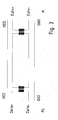
- FIG. 3 a section of a schematic diagram is shown.
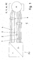
- FIG. 4 schematic diagram of an embodiment of the invention is shown.
- FIG. 5 is a modification of the embodiment according to FIG. 4 shown.
- FIG. 1 It is known to provide between a converter FU and an electric motor M, a cable connection having different lines for low power and high current.
- At least one respective connector is provided for each cable, so that the cable from the motor M, in particular an electric motor, and / or from the inverter FU is separable.
- the inverter FU is arranged in a control cabinet of a system, whereas the motor M in the mechanical part of the system, ie outside the cabinet, is arranged. This results in high cable lengths and complex wiring.
- At least one temperature sensor or a temperature-sensitive switch is arranged in the stator winding of the motor M.
- an angle sensor is arranged on the motor, whose signals contain information about the angular position of the rotor shaft of the electric motor M.
- a brake is arranged on the motor M, the braking force of which acts on the rotor shaft.
- the lines 1 for transmitting the information detected by the angle sensor are arranged in a hybrid cable 5 together with the power lines U, V, W, PE.
- Another cable 6 with low power lines 3 and 2 is necessary because not enough many low power cables can be integrated in the hybrid cable.
- the weak current lines 3 transmit the control voltage for the brake and the low-current lines 2 the analog temperature values detected. Appropriate connectors are providable.
- each track of this encoder are assigned two lines and the encoder has more than one track. The processing of these track signals then takes place in the inverter FU.
- the hybrid cable includes the power lines U, V, W, PE and additionally only a few low-voltage cables.
- the power lines U, V, W, PE are as weak current lines in a first embodiment according to FIG. 2 and 3 only two data + and data- lines are needed for a differential signal transmission along with supply lines GND and VDD.
- FIG. 3 shown is a galvanic isolation, so isolation realized by using a converter side and a motor-side transformer.
- the data can be arranged here as a data word, with each data word being composed by way of example by arranging brake-related data in a first word component, temperature sensor-related data in a second word component and angle sensor-related data in a third word component.
- Communication over the signal lines is bidirectional executable, so that the temperature sensor-related data and angle sensor-related data from the motor M to the inverter FU and the brake-related data from the inverter FU are transmitted to the motor M.
- the process data position and temperature can now be transferred from the motor to the inverter and the process data "brake on” or “brake off” coded by the inverter FU can be transmitted to the motor M.
- the low-voltage power supply lines can supply the brake, the temperature sensor and / or the encoder. For this example, 24 volts are applied between VDD and GND.
- the brake in this case comprises an electronic circuit which controls an electromagnet of the brake.
- the electronic circuit is supplied via said low-power supply lines VDD and GND.
- a power semiconductor switch encompassed by the electronic circuit controls the current of the electromagnet and receives its drive signal via the data lines Data + and Data-.
- the motor-side and / or converter-side galvanic isolation reduces interference.
- a circuit board is arranged in the motor M, which are supplied to the signals of the sensors and from which the electromagnet of the brake, so the actuator, its associated control current is supplied.
- a hybrid connector part is arranged as in the motor housing, in which the hybrid cable 20 is plug-connected by means of a corresponding arranged on an end portion of the hybrid cable 20 mating connector part and the associated lines are passed from the connector part to the circuit board.
- the hybrid cable 20 includes four lines 21 for low power, in particular two lines for the differential signal transmission and two lines for the supply voltage passage, and lines 22 for power, especially high current, ie motor phases U, V, W and neutral PE.
- the circuit board with its equipped electronic components as part of the angle sensor executable executes. Namely, if magnetic field-sensitive sensors, in particular Hall sensors and / or Wiegandsensoren are arranged on the circuit board and the printed circuit board is arranged in such a way that these magnetic field sensitive sensors are arranged opposite to a rotating rotatably connected to the rotor shaft of the motor part, are on the rotating part Permanent magnets can be arranged, which are detectable by the magnetic field-sensitive sensors and thus the angular position can be detected.
- the circuit board is exemplified fastened to a flange or other housing part of the engine.
- the control current for the electromagnet of the brake is controllable.
- an electronic circuit or a component can be provided on the printed circuit board, which is referred to as a converter and forms an interface between the sensor signals and the Sigrialtechnischen Data + and Data-.
- a memory is also provided on the printed circuit board, to which parameters to be stored via the signal lines can be fed.
- motor-related data in this memory which is preferably designed as a long-term memory, such as EEPROM or the like, or at least includes such a memory component, so that even in case of power failure, the stored parameters are not lost.
- a fan is preferably used, wherein the permanent magnets in the fan ring and / or in the fan blades and / or arranged in an outer circumference arranged shipsleitring the fan.
- an electromagnetically actuated brake is arranged on the motor. With sufficient current to the electromagnet, so brake coil, a Anchor plate attracted by the electromagnet, whereby a counteracting spring force is overcome. The armature disc releases the brake pads, whereby the brake is released. If there is insufficient energization, the spring force generating spring elements press the armature disk on the brake pad carrier, the brake pads are thus in turn pressed onto a braking surface. The brake then falls and generates braking torque or braking force.
- the brake pad carrier is axially displaceable and rotationally fixed on the rotor.
- the armature disk is arranged axially displaceable and non-rotatably arranged on the motor housing or stator.
- two of the low current lines 21 are power lines, which are operated to have two voltage states, illustratively a low voltage such as 7.5 volts, or alternatively a higher voltage 24 volts.
- the brake coil 30 is supplied and a voltage adjustment circuit 32, an electronic circuit 31, such as angle sensor with evaluation electronics or the like.
- the voltage adjustment circuit 32 generates a supply voltage of 5 volts for the electronic shading 31 from the voltage between the supply lines (GND, 24V / 7.5 V).
- the brake drive information is encoded with the electronic circuit 31 always powered.
- the information for brake control is thus independent of the data lines Data + and Dataaus woolbar. Even more data can be transmitted as a binary data stream by using the two voltage levels as HIGH and LOW signals.
- an angle sensor is preferably used with evaluation.
- a controllable semiconductor switch 40 in particular IGBT or MOSFET, is used to control the coil current, which is supplied from a drive circuit for the semiconductor switch 40, not shown, to which the supply voltage, only at the high voltage level, in particular 24 volts, the switch 40 in the conductive state is added.
- the brake is dimensioned so that it remains ventilated at both voltage levels, ie HIGH and LOW. Thus, the binary data stream is then transferable without disturbing the braking state.
- a bidirectional communication is executable.
- a half-duplex method is used herein.
- two further low-current lines are arranged as signal lines in the hybrid cable
Landscapes
- Engineering & Computer Science (AREA)
- Automation & Control Theory (AREA)
- Microelectronics & Electronic Packaging (AREA)
- Power Engineering (AREA)
- Computer Networks & Wireless Communication (AREA)
- Signal Processing (AREA)
- Inverter Devices (AREA)
- Control Of Motors That Do Not Use Commutators (AREA)
- Braking Arrangements (AREA)
- Electric Propulsion And Braking For Vehicles (AREA)
Claims (15)
- Système d'entraînement, qui présente au moins un moteur électrique (M), lequel est alimenté par un variateur (FU),
le variateur (FU) et le moteur étant reliés par un système de câbles, en particulier un câble hybride (5, 20),
le système de câbles présentant des lignes à courant fort (4) pour alimenter le moteur et des lignes à courant faible (21),
les lignes à courant faible (21) présentant deux lignes d'alimentation pour alimenter un circuit électronique (31) côté moteur, en particulier pour un capteur d'angle avec électronique d'évaluation,
les lignes d'alimentation (21) alimentant la bobine de frein (30) d'un frein, en particulier pour produire un couple s'opposant au couple produit par le moteur, respectivement une force s'opposant à la force produite par le moteur,
caractérisé en ce que
le circuit électronique (31) est alimenté par un circuit d'adaptation de tension (32) à partir des lignes d'alimentation (21), en particulier pour mettre à disposition une tension d'alimentation pour le circuit électronique (31) produite indépendamment du niveau de tension des lignes d'alimentation (21),
en particulier le moteur étant un moteur linéaire ou un moteur rotatif,
les deux lignes d'alimentation (21) fonctionnant de façon qu'elles présentent soit un premier état de tension dans lequel elles mettent à disposition une basse tension, en particulier telle que 7,5 volts, soit un deuxième état de tension dans lequel elles mettent à disposition une tension plus élevée, en particulier telle que 24 volts, et
ces deux niveaux de tension servant au codage d'une information de commande du frein. - Système d'entraînement selon au moins l'une des revendications précédentes,
caractérisé en ce
que le frein, en particulier le nombre d'enroulements, les dimensions géométriques et les propriétés des matériaux du frein avec bobine de frein (30) sont dimensionnés de façon que celui-ci reste desserré dans le cas d'un niveau de tension qui dépasse la tension d'alimentation du circuit électronique. - Système d'entraînement selon au moins l'une des revendications précédentes,
caractérisé en ce
qu'au moins un capteur et un actionneur sont disposés sur le moteur en tant que circuit électronique (31)
et/ou
qu'un commutateur commandable, en particulier un IGBT ou un MOSFET, est disposé dans le trajet du courant entre une ligne d'alimentation et la bobine de frein (30) pour commander le courant de bobine de frein,
et/ou
que le circuit d'adaptation de tension (32) abaisse par division une tension d'alimentation pour le circuit électronique (31) à partir du niveau de tension régnant sur les lignes d'alimentation (3). - Système d'entraînement selon au moins l'une des revendications précédentes,
caractérisé en ce
qu'au moins deux ou seulement une ou deux lignes de signalisation (1) et deux lignes d'alimentation (3), en particulier pour l'alimentation 24 volts, sont utilisées comme lignes à courant faible (21),
les valeurs détectées par les capteurs et les données de commande destinées à l'actionneur - en particulier décalées dans le temps - pouvant être transmises via les lignes de signalisation (1). - Système d'entraînement selon au moins l'une des revendications précédentes,
caractérisé en ce
qu'un capteur de température, en particulier un capteur de température disposé dans les enroulements de stator du moteur, et/ou un capteur d'angle et, en tant qu'actionneur, un frein actionnable par voie électromagnétique, dont le couple de freinage peut être transmis à l'arbre de rotor du moteur, sont disposés sur le moteur. - Système d'entraînement selon au moins l'une des revendications précédentes,
caractérisé en ce que
le câble hybride (5, 20) est relié au moteur par une connexion enfichable et/ou au variateur (FU) par une autre connexion enfichable. - Système d'entraînement selon au moins l'une des revendications précédentes,
caractérisé en ce
qu'un moyen de séparation galvanique, en particulier un transformateur, est disposé entre le moteur et les lignes du câble hybride (5, 20), en particulier les lignes à courant faible (21) du câble hybride (5, 20),
et/ou
qu'un moyen de séparation galvanique, en particulier un transformateur, est disposé entre le moteur et les lignes (21) du câble hybride (5, 20), en particulier les lignes à courant faible (21) du câble hybride (5, 20). - Système d'entraînement selon au moins l'une des revendications précédentes,
caractérisé en ce
que les lignes de signalisation (1) agissent comme des lignes de transmission de signaux différentielles. - Système d'entraînement selon au moins l'une des revendications précédentes,
caractérisé en ce
que les lignes à courant fort (4, 22) comprennent les lignes d'alimentation des phases du moteur (U, V, W) et un conducteur neutre (PE). - Système d'entraînement selon au moins l'une des revendications précédentes,
caractérisé en ce
qu'un commutateur à semi-conducteurs commandable (40) est disposé dans le moteur, auquel peut être amené le signal de commande du variateur (FU) via les lignes de signalisation (1) du câble hybride (5, 20) et lequel commande le courant amené à l'électro-aimant du frein. - Système d'entraînement selon au moins l'une des revendications précédentes,
caractérisé en ce
qu'une carte de circuits imprimés est disposée dans le moteur, en particulier sur une partie formant au moins partiellement le carter, laquelle est équipée du commutateur à semi-conducteurs (40),
la carte de circuits imprimés étant également équipée d'un capteur sensible au champ magnétique, en particulier un capteur à effet Hall et/ou un capteur Wiegand, lequel est disposé en face d'une partie montée tournante, en particulier d'un ventilateur, des aimants permanents étant disposés sur la partie montée tournante, lesquels sont détectables par le capteur sensible au champ magnétique lors de leur rotation devant celui-ci,
et/ou
qu'un convertisseur est disposé sur la carte de circuits imprimés, lequel reçoit les données transmises via les lignes de signalisation (1) sous la forme d'une information numérique, en extrait par filtrage les informations de commande pour l'actionneur, en particulier le commutateur à semi-conducteurs (40), et transmet au variateur (FU) les signaux provenant des capteurs, en particulier du capteur d'angle et du capteur de température, sous la forme d'un flux de données numériques via les lignes de signalisation (1). - Système d'entraînement selon au moins l'une des revendications précédentes,
caractérisé en ce
que deux autres lignes de signalisation (1) sont disposées dans le câble hybride (5, 20), de sorte que le système d'entraînement peut être utilisé dans des installations de sécurité,
en particulier le flux de données numériques étant transmis de façon redondante ou des informations de contrôle étant transmises via le flux de données numériques. - Procédé permettant de faire fonctionner un système d'entraînement, en particulier selon au moins l'une des revendications précédentes,
le système d'entraînement présentant au moins un moteur électrique (M), lequel est alimenté par un variateur (FU),
le variateur (FU) et le moteur étant reliés par un système de câbles, en particulier un câble hybride (5, 20),
caractérisé en ce que
le système de câbles présente des lignes à courant fort (4) pour alimenter le moteur et des lignes à courant faible (21),
les lignes à courant faible (21) présentant deux lignes d'alimentation pour alimenter un circuit électronique (31) côté moteur, en particulier pour un capteur d'angle avec électronique d'évaluation,
les lignes d'alimentation (21) alimentant aussi la bobine de frein (30) d'un frein, en particulier d'un frein relié mécaniquement au moteur, en particulier pour produire un couple s'opposant au couple produit par le moteur, respectivement une force s'opposant à la force produite par le moteur,
caractérisé en ce que
le circuit électronique (31) est alimenté par un circuit d'adaptation de tension (32) à partir des lignes d'alimentation (21), en particulier une tension d'alimentation pour le circuit électronique (31) produite indépendamment du niveau de tension des lignes d'alimentation (21) étant mise à disposition,
différents niveaux étant appliqués côté variateur sur les lignes d'alimentation (21) pour transmettre une information de commande du frein,
à savoir comme premier niveau une basse tension, en particulier telle que 7,5 volts, comme deuxième niveau une tension plus élevée, en particulier telle que 24 volts,
en particulier les signaux étant décodés côté moteur,
en particulier le moteur étant un moteur linéaire ou un moteur rotatif. - Procédé selon au moins l'une des revendications précédentes,
caractérisé en ce
que deux niveaux différents sont utilisés pour le codage sur les lignes d'alimentation (3),
le niveau plus bas provoquant un desserrage du frein et le niveau plus élevé des deux niveaux provoquant un serrage du frein. - Procédé selon au moins l'une des revendications précédentes,
caractérisé en ce
que les données sont codées numériquement sur les lignes de signalisation (1) de façon que les tranches de temps de tension négative et positive soient de même longueur, en particulier les tranches de temps étant chacune assez courte pour que des transformateurs utilisés comme moyens de séparation galvanique ne soient pas saturés,
et/ou
les données sont transmises en codage Manchester sur les lignes de signalisation (1),
en particulier les données étant transmises de façon bidirectionnelle, en particulier un procédé semi-duplex étant utilisé,
en particulier les données des capteurs et actionneurs étant transmises en série les unes derrière les autres dans un mot de données.
Applications Claiming Priority (2)
| Application Number | Priority Date | Filing Date | Title |
|---|---|---|---|
| DE201110100361 DE102011100361A1 (de) | 2011-05-03 | 2011-05-03 | Antriebssystem und Verfahren zum Betreiben eines Antriebssystems |
| PCT/EP2012/001584 WO2012149996A2 (fr) | 2011-05-03 | 2012-04-12 | Système d'entraînement et procédé permettant de faire fonctionner un système d'entraînement |
Publications (2)
| Publication Number | Publication Date |
|---|---|
| EP2705413A2 EP2705413A2 (fr) | 2014-03-12 |
| EP2705413B1 true EP2705413B1 (fr) | 2015-06-10 |
Family
ID=45954599
Family Applications (1)
| Application Number | Title | Priority Date | Filing Date |
|---|---|---|---|
| EP12714229.7A Active EP2705413B1 (fr) | 2011-05-03 | 2012-04-12 | Système d'entraînement et procédé permettant de faire fonctionner un système d'entraînement |
Country Status (3)
| Country | Link |
|---|---|
| EP (1) | EP2705413B1 (fr) |
| DE (1) | DE102011100361A1 (fr) |
| WO (1) | WO2012149996A2 (fr) |
Cited By (1)
| Publication number | Priority date | Publication date | Assignee | Title |
|---|---|---|---|---|
| DE102018000509A1 (de) | 2017-02-02 | 2018-08-02 | Sew-Eurodrive Gmbh & Co Kg | Hybridkabel mit integriertem Lichtwellenleiter |
Families Citing this family (8)
| Publication number | Priority date | Publication date | Assignee | Title |
|---|---|---|---|---|
| DE102013007649B4 (de) * | 2013-05-06 | 2018-05-24 | Sew-Eurodrive Gmbh & Co Kg | System und Verfahren zum Betreiben eines Systems |
| EP2851909B1 (fr) * | 2013-09-18 | 2017-08-02 | Siemens Aktiengesellschaft | Système d'entraînement avec commande combinée du frein et du capteur |
| DE102013016584B4 (de) | 2013-10-08 | 2024-05-08 | Sew-Eurodrive Gmbh & Co Kg | System mit mindestens einer aus einer Zentraleinheit und Elektrogeräten, insbesondere Antrieben, gebildeten seriellen Anordnung und Verfahren |
| DE102013018271B4 (de) * | 2013-10-31 | 2016-05-12 | Sew-Eurodrive Gmbh & Co Kg | Antriebssystem |
| DE102015005939B3 (de) * | 2015-05-12 | 2016-08-11 | Sew-Eurodrive Gmbh & Co Kg | Verfahren und System zum Betreiben einer elektrischen Schnittstelle |
| DE102015013290A1 (de) * | 2015-10-15 | 2017-04-20 | Sew-Eurodrive Gmbh & Co Kg | Antrieb, aufweisend einen von einem Umrichter über erste elektrische Leitungen gespeisten Elektromotor und eine Bremse und Verfahren zum Betreiben eines Antriebs |
| DE102017117090A1 (de) * | 2017-07-28 | 2019-01-31 | Hengstler Gmbh | Verfahren zur Ansteuerung eines gebremsten Servomotors oder eines Linearantriebes mit einer Kontrolleinheit |
| DE102023000222A1 (de) | 2022-02-16 | 2023-08-17 | Sew-Eurodrive Gmbh & Co Kg | Antriebssystem |
Family Cites Families (7)
| Publication number | Priority date | Publication date | Assignee | Title |
|---|---|---|---|---|
| DE19523848C1 (de) * | 1995-06-30 | 1996-11-28 | Deemotors Vertriebs Gmbh | Verfahren zum Betreiben eines Asynchronmotors |
| DE19905952C2 (de) * | 1999-02-12 | 2001-04-05 | Sew Eurodrive Gmbh & Co | Verteilerkasten |
| DE19908045C2 (de) * | 1999-02-24 | 2001-10-04 | Sew Eurodrive Gmbh & Co | Kabelsystem, umfassend Kabel zur Verkabelung mindestens eines Umrichters mit Elektromotor |
| DE102005027502B4 (de) * | 2004-10-22 | 2009-07-09 | Sew-Eurodrive Gmbh & Co. Kg | Elektromagnetisch betätigbare Bremse, Vorrichtung zur sicheren Ansteuerung einer elektromagnetisch betätigbaren Bremse, Elektromotor und Bremse |
| DE102007041237A1 (de) * | 2007-08-30 | 2009-03-05 | Endress + Hauser Conducta Gesellschaft für Mess- und Regeltechnik mbH + Co. KG | Verfahren und Vorrichtung zur Übertragung von Energie und Daten |
| DE102008058303B4 (de) * | 2008-11-19 | 2022-08-11 | Sew-Eurodrive Gmbh & Co Kg | Verfahren zum Betreiben eines Antriebs und Antriebssystem |
| DE102008054994B4 (de) * | 2008-12-19 | 2022-07-28 | Robert Bosch Gmbh | Verfahren und Vorrichtung zur Spannungsversorgung von einem analogen Sensor |
-
2011
- 2011-05-03 DE DE201110100361 patent/DE102011100361A1/de active Pending
-
2012
- 2012-04-12 EP EP12714229.7A patent/EP2705413B1/fr active Active
- 2012-04-12 WO PCT/EP2012/001584 patent/WO2012149996A2/fr not_active Ceased
Cited By (1)
| Publication number | Priority date | Publication date | Assignee | Title |
|---|---|---|---|---|
| DE102018000509A1 (de) | 2017-02-02 | 2018-08-02 | Sew-Eurodrive Gmbh & Co Kg | Hybridkabel mit integriertem Lichtwellenleiter |
Also Published As
| Publication number | Publication date |
|---|---|
| WO2012149996A2 (fr) | 2012-11-08 |
| EP2705413A2 (fr) | 2014-03-12 |
| DE102011100361A1 (de) | 2012-11-08 |
| WO2012149996A3 (fr) | 2013-06-06 |
Similar Documents
| Publication | Publication Date | Title |
|---|---|---|
| EP2705413B1 (fr) | Système d'entraînement et procédé permettant de faire fonctionner un système d'entraînement | |
| EP2689530B1 (fr) | Système d'entraînement et procédé de fonctionnement d'un système d'entraînement | |
| EP2863184B1 (fr) | Capteur de rotation avec alimentation autonome en énergie | |
| WO2013127535A2 (fr) | Moteur électrique | |
| EP2832580A2 (fr) | Système d'entraînement pour un entraînement de man'uvre de remorque de véhicule | |
| WO2005064764A1 (fr) | Installation | |
| DE102022116680A1 (de) | Fremderregte Synchronmaschine und Kraftfahrzeug | |
| DE102015005939B3 (de) | Verfahren und System zum Betreiben einer elektrischen Schnittstelle | |
| EP1805885B1 (fr) | Frein electromagnetique, dispositif de commande sure d'un frein electromagnetique, moteur electrique et frein | |
| DE102013006730A1 (de) | Anlage mit Anschlusseinheit, Elektromotor und Motorsteuereinheit und Kabel | |
| EP2633618B2 (fr) | Entraînement | |
| DE102015206975A1 (de) | Aktuatoreinheit für ein Getriebe eines Kraftfahrzeugs | |
| DE102005006286B4 (de) | Elektrischer Antrieb | |
| DE102019004843A1 (de) | Verfahren zum Betreiben eines Antriebssystems und Antriebssystem | |
| EP3363100B1 (fr) | Transmission comprenant un moteur électrique alimenté par un convertisseur par l'intermédiaire de câbles électriques, et un frein, ainsi que procédé de fonctionnement de ce mécanisme d'entraînement | |
| EP2082491B1 (fr) | Installation et procédé permettant de la faire fonctionner | |
| DE102006034049B4 (de) | Elektromagnetisch betätigbare Bremse oder Kupplung mit Lüftspule, Verfahren zum Betreiben derselben und Antrieb | |
| WO2017001052A2 (fr) | Actionneur et procédés correspondants | |
| DE102009020506A1 (de) | Antrieb und Verfahren zur Herstellung eines Antriebs | |
| DE102019004845A1 (de) | Antriebssystem mit sicherheitsgerichteter Ansteuerung im Anschlusskasten | |
| DE102019004846A1 (de) | Antriebssystem | |
| DE102022004807A1 (de) | Antriebssystem | |
| DE102006030335B4 (de) | Anlage mit Antrieben unter einem Drehtisch | |
| DE102011103884A1 (de) | Verfahren zum Betreiben einer Anlage und Anlage | |
| DE102023000222A1 (de) | Antriebssystem |
Legal Events
| Date | Code | Title | Description |
|---|---|---|---|
| PUAI | Public reference made under article 153(3) epc to a published international application that has entered the european phase |
Free format text: ORIGINAL CODE: 0009012 |
|
| 17P | Request for examination filed |
Effective date: 20131206 |
|
| AK | Designated contracting states |
Kind code of ref document: A2 Designated state(s): AL AT BE BG CH CY CZ DE DK EE ES FI FR GB GR HR HU IE IS IT LI LT LU LV MC MK MT NL NO PL PT RO RS SE SI SK SM TR |
|
| DAX | Request for extension of the european patent (deleted) | ||
| GRAP | Despatch of communication of intention to grant a patent |
Free format text: ORIGINAL CODE: EPIDOSNIGR1 |
|
| INTG | Intention to grant announced |
Effective date: 20150123 |
|
| GRAS | Grant fee paid |
Free format text: ORIGINAL CODE: EPIDOSNIGR3 |
|
| GRAA | (expected) grant |
Free format text: ORIGINAL CODE: 0009210 |
|
| AK | Designated contracting states |
Kind code of ref document: B1 Designated state(s): AL AT BE BG CH CY CZ DE DK EE ES FI FR GB GR HR HU IE IS IT LI LT LU LV MC MK MT NL NO PL PT RO RS SE SI SK SM TR |
|
| REG | Reference to a national code |
Ref country code: GB Ref legal event code: FG4D Free format text: NOT ENGLISH |
|
| REG | Reference to a national code |
Ref country code: CH Ref legal event code: EP |
|
| REG | Reference to a national code |
Ref country code: AT Ref legal event code: REF Ref document number: 731158 Country of ref document: AT Kind code of ref document: T Effective date: 20150715 |
|
| REG | Reference to a national code |
Ref country code: DE Ref legal event code: R096 Ref document number: 502012003411 Country of ref document: DE |
|
| REG | Reference to a national code |
Ref country code: IE Ref legal event code: FG4D Free format text: LANGUAGE OF EP DOCUMENT: GERMAN |
|
| PG25 | Lapsed in a contracting state [announced via postgrant information from national office to epo] |
Ref country code: LT Free format text: LAPSE BECAUSE OF FAILURE TO SUBMIT A TRANSLATION OF THE DESCRIPTION OR TO PAY THE FEE WITHIN THE PRESCRIBED TIME-LIMIT Effective date: 20150610 Ref country code: FI Free format text: LAPSE BECAUSE OF FAILURE TO SUBMIT A TRANSLATION OF THE DESCRIPTION OR TO PAY THE FEE WITHIN THE PRESCRIBED TIME-LIMIT Effective date: 20150610 Ref country code: ES Free format text: LAPSE BECAUSE OF FAILURE TO SUBMIT A TRANSLATION OF THE DESCRIPTION OR TO PAY THE FEE WITHIN THE PRESCRIBED TIME-LIMIT Effective date: 20150610 Ref country code: NO Free format text: LAPSE BECAUSE OF FAILURE TO SUBMIT A TRANSLATION OF THE DESCRIPTION OR TO PAY THE FEE WITHIN THE PRESCRIBED TIME-LIMIT Effective date: 20150910 |
|
| REG | Reference to a national code |
Ref country code: NL Ref legal event code: MP Effective date: 20150610 |
|
| PG25 | Lapsed in a contracting state [announced via postgrant information from national office to epo] |
Ref country code: LV Free format text: LAPSE BECAUSE OF FAILURE TO SUBMIT A TRANSLATION OF THE DESCRIPTION OR TO PAY THE FEE WITHIN THE PRESCRIBED TIME-LIMIT Effective date: 20150610 Ref country code: RS Free format text: LAPSE BECAUSE OF FAILURE TO SUBMIT A TRANSLATION OF THE DESCRIPTION OR TO PAY THE FEE WITHIN THE PRESCRIBED TIME-LIMIT Effective date: 20150610 Ref country code: BG Free format text: LAPSE BECAUSE OF FAILURE TO SUBMIT A TRANSLATION OF THE DESCRIPTION OR TO PAY THE FEE WITHIN THE PRESCRIBED TIME-LIMIT Effective date: 20150910 Ref country code: GR Free format text: LAPSE BECAUSE OF FAILURE TO SUBMIT A TRANSLATION OF THE DESCRIPTION OR TO PAY THE FEE WITHIN THE PRESCRIBED TIME-LIMIT Effective date: 20150911 |
|
| PG25 | Lapsed in a contracting state [announced via postgrant information from national office to epo] |
Ref country code: EE Free format text: LAPSE BECAUSE OF FAILURE TO SUBMIT A TRANSLATION OF THE DESCRIPTION OR TO PAY THE FEE WITHIN THE PRESCRIBED TIME-LIMIT Effective date: 20150610 |
|
| REG | Reference to a national code |
Ref country code: FR Ref legal event code: PLFP Year of fee payment: 5 |
|
| PG25 | Lapsed in a contracting state [announced via postgrant information from national office to epo] |
Ref country code: IS Free format text: LAPSE BECAUSE OF FAILURE TO SUBMIT A TRANSLATION OF THE DESCRIPTION OR TO PAY THE FEE WITHIN THE PRESCRIBED TIME-LIMIT Effective date: 20151010 Ref country code: SK Free format text: LAPSE BECAUSE OF FAILURE TO SUBMIT A TRANSLATION OF THE DESCRIPTION OR TO PAY THE FEE WITHIN THE PRESCRIBED TIME-LIMIT Effective date: 20150610 Ref country code: CZ Free format text: LAPSE BECAUSE OF FAILURE TO SUBMIT A TRANSLATION OF THE DESCRIPTION OR TO PAY THE FEE WITHIN THE PRESCRIBED TIME-LIMIT Effective date: 20150610 Ref country code: PL Free format text: LAPSE BECAUSE OF FAILURE TO SUBMIT A TRANSLATION OF THE DESCRIPTION OR TO PAY THE FEE WITHIN THE PRESCRIBED TIME-LIMIT Effective date: 20150610 Ref country code: PT Free format text: LAPSE BECAUSE OF FAILURE TO SUBMIT A TRANSLATION OF THE DESCRIPTION OR TO PAY THE FEE WITHIN THE PRESCRIBED TIME-LIMIT Effective date: 20151012 Ref country code: RO Free format text: LAPSE BECAUSE OF NON-PAYMENT OF DUE FEES Effective date: 20150610 |
|
| REG | Reference to a national code |
Ref country code: DE Ref legal event code: R097 Ref document number: 502012003411 Country of ref document: DE |
|
| PLBE | No opposition filed within time limit |
Free format text: ORIGINAL CODE: 0009261 |
|
| STAA | Information on the status of an ep patent application or granted ep patent |
Free format text: STATUS: NO OPPOSITION FILED WITHIN TIME LIMIT |
|
| PG25 | Lapsed in a contracting state [announced via postgrant information from national office to epo] |
Ref country code: DK Free format text: LAPSE BECAUSE OF FAILURE TO SUBMIT A TRANSLATION OF THE DESCRIPTION OR TO PAY THE FEE WITHIN THE PRESCRIBED TIME-LIMIT Effective date: 20150610 Ref country code: IT Free format text: LAPSE BECAUSE OF FAILURE TO SUBMIT A TRANSLATION OF THE DESCRIPTION OR TO PAY THE FEE WITHIN THE PRESCRIBED TIME-LIMIT Effective date: 20150610 |
|
| 26N | No opposition filed |
Effective date: 20160311 |
|
| PG25 | Lapsed in a contracting state [announced via postgrant information from national office to epo] |
Ref country code: SI Free format text: LAPSE BECAUSE OF FAILURE TO SUBMIT A TRANSLATION OF THE DESCRIPTION OR TO PAY THE FEE WITHIN THE PRESCRIBED TIME-LIMIT Effective date: 20150610 |
|
| PG25 | Lapsed in a contracting state [announced via postgrant information from national office to epo] |
Ref country code: BE Free format text: LAPSE BECAUSE OF NON-PAYMENT OF DUE FEES Effective date: 20160430 |
|
| REG | Reference to a national code |
Ref country code: CH Ref legal event code: PL |
|
| PG25 | Lapsed in a contracting state [announced via postgrant information from national office to epo] |
Ref country code: LU Free format text: LAPSE BECAUSE OF FAILURE TO SUBMIT A TRANSLATION OF THE DESCRIPTION OR TO PAY THE FEE WITHIN THE PRESCRIBED TIME-LIMIT Effective date: 20160412 |
|
| REG | Reference to a national code |
Ref country code: IE Ref legal event code: MM4A |
|
| PG25 | Lapsed in a contracting state [announced via postgrant information from national office to epo] |
Ref country code: LI Free format text: LAPSE BECAUSE OF NON-PAYMENT OF DUE FEES Effective date: 20160430 Ref country code: CH Free format text: LAPSE BECAUSE OF NON-PAYMENT OF DUE FEES Effective date: 20160430 |
|
| REG | Reference to a national code |
Ref country code: FR Ref legal event code: PLFP Year of fee payment: 6 |
|
| PG25 | Lapsed in a contracting state [announced via postgrant information from national office to epo] |
Ref country code: IE Free format text: LAPSE BECAUSE OF NON-PAYMENT OF DUE FEES Effective date: 20160412 |
|
| PG25 | Lapsed in a contracting state [announced via postgrant information from national office to epo] |
Ref country code: NL Free format text: LAPSE BECAUSE OF FAILURE TO SUBMIT A TRANSLATION OF THE DESCRIPTION OR TO PAY THE FEE WITHIN THE PRESCRIBED TIME-LIMIT Effective date: 20150610 Ref country code: SE Free format text: LAPSE BECAUSE OF FAILURE TO SUBMIT A TRANSLATION OF THE DESCRIPTION OR TO PAY THE FEE WITHIN THE PRESCRIBED TIME-LIMIT Effective date: 20150610 |
|
| REG | Reference to a national code |
Ref country code: FR Ref legal event code: PLFP Year of fee payment: 7 |
|
| PG25 | Lapsed in a contracting state [announced via postgrant information from national office to epo] |
Ref country code: CY Free format text: LAPSE BECAUSE OF FAILURE TO SUBMIT A TRANSLATION OF THE DESCRIPTION OR TO PAY THE FEE WITHIN THE PRESCRIBED TIME-LIMIT Effective date: 20150610 Ref country code: HU Free format text: LAPSE BECAUSE OF FAILURE TO SUBMIT A TRANSLATION OF THE DESCRIPTION OR TO PAY THE FEE WITHIN THE PRESCRIBED TIME-LIMIT; INVALID AB INITIO Effective date: 20120412 Ref country code: SM Free format text: LAPSE BECAUSE OF FAILURE TO SUBMIT A TRANSLATION OF THE DESCRIPTION OR TO PAY THE FEE WITHIN THE PRESCRIBED TIME-LIMIT Effective date: 20150610 |
|
| REG | Reference to a national code |
Ref country code: AT Ref legal event code: MM01 Ref document number: 731158 Country of ref document: AT Kind code of ref document: T Effective date: 20170412 |
|
| PG25 | Lapsed in a contracting state [announced via postgrant information from national office to epo] |
Ref country code: MT Free format text: LAPSE BECAUSE OF FAILURE TO SUBMIT A TRANSLATION OF THE DESCRIPTION OR TO PAY THE FEE WITHIN THE PRESCRIBED TIME-LIMIT Effective date: 20150610 Ref country code: HR Free format text: LAPSE BECAUSE OF FAILURE TO SUBMIT A TRANSLATION OF THE DESCRIPTION OR TO PAY THE FEE WITHIN THE PRESCRIBED TIME-LIMIT Effective date: 20150610 Ref country code: MC Free format text: LAPSE BECAUSE OF FAILURE TO SUBMIT A TRANSLATION OF THE DESCRIPTION OR TO PAY THE FEE WITHIN THE PRESCRIBED TIME-LIMIT Effective date: 20150610 Ref country code: TR Free format text: LAPSE BECAUSE OF FAILURE TO SUBMIT A TRANSLATION OF THE DESCRIPTION OR TO PAY THE FEE WITHIN THE PRESCRIBED TIME-LIMIT Effective date: 20150610 Ref country code: MK Free format text: LAPSE BECAUSE OF FAILURE TO SUBMIT A TRANSLATION OF THE DESCRIPTION OR TO PAY THE FEE WITHIN THE PRESCRIBED TIME-LIMIT Effective date: 20150610 |
|
| PG25 | Lapsed in a contracting state [announced via postgrant information from national office to epo] |
Ref country code: AT Free format text: LAPSE BECAUSE OF NON-PAYMENT OF DUE FEES Effective date: 20170412 |
|
| PG25 | Lapsed in a contracting state [announced via postgrant information from national office to epo] |
Ref country code: AL Free format text: LAPSE BECAUSE OF FAILURE TO SUBMIT A TRANSLATION OF THE DESCRIPTION OR TO PAY THE FEE WITHIN THE PRESCRIBED TIME-LIMIT Effective date: 20150610 |
|
| PGFP | Annual fee paid to national office [announced via postgrant information from national office to epo] |
Ref country code: DE Payment date: 20250430 Year of fee payment: 14 |
|
| REG | Reference to a national code |
Ref country code: DE Ref legal event code: R084 Ref document number: 502012003411 Country of ref document: DE |
|
| PGFP | Annual fee paid to national office [announced via postgrant information from national office to epo] |
Ref country code: GB Payment date: 20260312 Year of fee payment: 15 |
|
| PGFP | Annual fee paid to national office [announced via postgrant information from national office to epo] |
Ref country code: FR Payment date: 20260309 Year of fee payment: 15 |