EP2633618B2 - Entraînement - Google Patents
Entraînement Download PDFInfo
- Publication number
- EP2633618B2 EP2633618B2 EP11788362.9A EP11788362A EP2633618B2 EP 2633618 B2 EP2633618 B2 EP 2633618B2 EP 11788362 A EP11788362 A EP 11788362A EP 2633618 B2 EP2633618 B2 EP 2633618B2
- Authority
- EP
- European Patent Office
- Prior art keywords
- sensor
- circuit board
- insulating means
- material measure
- printed circuit
- Prior art date
- Legal status (The legal status is an assumption and is not a legal conclusion. Google has not performed a legal analysis and makes no representation as to the accuracy of the status listed.)
- Active
Links
Images


Classifications
-
- H—ELECTRICITY
- H02—GENERATION; CONVERSION OR DISTRIBUTION OF ELECTRIC POWER
- H02K—DYNAMO-ELECTRIC MACHINES
- H02K29/00—Motors or generators having non-mechanical commutating devices, e.g. discharge tubes or semiconductor devices
- H02K29/06—Motors or generators having non-mechanical commutating devices, e.g. discharge tubes or semiconductor devices with position sensing devices
- H02K29/08—Motors or generators having non-mechanical commutating devices, e.g. discharge tubes or semiconductor devices with position sensing devices using magnetic effect devices, e.g. Hall-plates, magneto-resistors
-
- H—ELECTRICITY
- H02—GENERATION; CONVERSION OR DISTRIBUTION OF ELECTRIC POWER
- H02K—DYNAMO-ELECTRIC MACHINES
- H02K11/00—Structural association of dynamo-electric machines with electric components or with devices for shielding, monitoring or protection
- H02K11/20—Structural association of dynamo-electric machines with electric components or with devices for shielding, monitoring or protection for measuring, monitoring, testing, protecting or switching
- H02K11/21—Devices for sensing speed or position, or actuated thereby
- H02K11/215—Magnetic effect devices, e.g. Hall-effect or magneto-resistive elements
-
- H—ELECTRICITY
- H02—GENERATION; CONVERSION OR DISTRIBUTION OF ELECTRIC POWER
- H02K—DYNAMO-ELECTRIC MACHINES
- H02K2203/00—Specific aspects not provided for in the other groups of this subclass relating to the windings
- H02K2203/03—Machines characterised by the wiring boards, i.e. printed circuit boards or similar structures for connecting the winding terminations
-
- H—ELECTRICITY
- H02—GENERATION; CONVERSION OR DISTRIBUTION OF ELECTRIC POWER
- H02M—APPARATUS FOR CONVERSION BETWEEN AC AND AC, BETWEEN AC AND DC, OR BETWEEN DC AND DC, AND FOR USE WITH MAINS OR SIMILAR POWER SUPPLY SYSTEMS; CONVERSION OF DC OR AC INPUT POWER INTO SURGE OUTPUT POWER; CONTROL OR REGULATION THEREOF
- H02M5/00—Conversion of AC power input into AC power output, e.g. for change of voltage, for change of frequency, for change of number of phases
- H02M5/40—Conversion of AC power input into AC power output, e.g. for change of voltage, for change of frequency, for change of number of phases with intermediate conversion into DC
- H02M5/42—Conversion of AC power input into AC power output, e.g. for change of voltage, for change of frequency, for change of number of phases with intermediate conversion into DC by static converters
- H02M5/44—Conversion of AC power input into AC power output, e.g. for change of voltage, for change of frequency, for change of number of phases with intermediate conversion into DC by static converters using discharge tubes or semiconductor devices to convert the intermediate DC into AC
- H02M5/453—Conversion of AC power input into AC power output, e.g. for change of voltage, for change of frequency, for change of number of phases with intermediate conversion into DC by static converters using discharge tubes or semiconductor devices to convert the intermediate DC into AC using devices of a triode or transistor type requiring continuous application of a control signal
- H02M5/458—Conversion of AC power input into AC power output, e.g. for change of voltage, for change of frequency, for change of number of phases with intermediate conversion into DC by static converters using discharge tubes or semiconductor devices to convert the intermediate DC into AC using devices of a triode or transistor type requiring continuous application of a control signal using semiconductor devices only
Definitions
- the invention relates to a drive.
- the invention is therefore based on the object of developing a drive, wherein the most compact and inexpensive arrangement possible.
- the drive comprises an converter-fed electric motor on which a sensor for detecting the angular position of a shaft, in particular a rotor shaft, of the electric motor is arranged, the converter having signal electronics, in particular comprising a controller, and power electronics, in particular comprising an inverter which feeds the motor, thereby the sensor signals are fed to the signal electronics, in particular directly, that is to say without galvanic isolation.
- the advantage here is that components for electrical isolation can be dispensed with, thus achieving the most compact and inexpensive design possible.
- the senor is galvanically connected to the signal electronics.
- the sensor comprises sensor electronics, that is to say a printed circuit board equipped with electronic components, which processes signals from the Hall sensors and Wigand sensors comprised by the sensor electronics.
- a material measure is arranged on the shaft, in particular a material measure is arranged on an axial end region of the shaft.
- the senor is in operative connection with the material measure, in particular detects the material measure, in particular for detecting the angular position.
- an insulating means in particular for electrical insulation, is arranged between the material measure and the sensor.
- the advantage here is that a compact arrangement can be achieved. The magnetic fields penetrate the insulating material essentially undisturbed, but the electrical insulation is improved.
- the distance between the material measure and the sensor is so small and the insulation strength and / or dielectric strength of the insulation means is so high that when the electrical insulation means is removed, an electrical breakdown takes place or is at least very likely, in particular at least in unfavorable weather conditions or ambient conditions.
- the advantage here is that a more compact arrangement than with mere use of air can be carried out.
- the distance between the material measure and the printed circuit board with components, such as a Hall sensor and / or Wiegand sensor can be kept short.
- the insulating means is arranged on or in potting compound and / or on or in adhesive, the potting compound or adhesive also being connected to a circuit board of the sensor and / or to components fitted on the circuit board of the sensor.
- the advantage here is that a cohesive holding of the insulating means can be effected and thus a secure holding is ensured.
- the potting compound and / or the adhesive itself can be made from an insulating material, so that a high insulating strength can be achieved.
- the insulating means is made of a material that has a higher electrical insulating strength than air, in particular at least five times higher.
- the advantage here is that a small distance between the material measure and the printed circuit board can be achieved.
- the insulating means is designed as a rigid plate.
- the advantage here is that simple assembly with adhesive or potting compound can be carried out.
- the insulating means is designed as a flexible film, in particular a self-adhesive film, and at least partially covers the printed circuit board equipped with components on its side facing the measuring standard.
- a flexible film in particular a self-adhesive film
- the film adapts its shape to the surface of the printed circuit board equipped with components.
- the insulating means is designed as a preformed film, in particular a self-adhesive film, and at least partially covers the printed circuit board equipped with components on its side facing the material measure. Is an advantage while ensuring that simple, quick positioning can be achieved during assembly.
- the insulating means is arranged between the material measure and at least a partial area of the adhesive or the potting compound.
- the advantage here is that a potting of the insulating agent or an arrangement on the surface of the adhesive or the potting compound is made possible.
- the material measure is a permanent magnet, in particular a permanent magnet magnetized in the radial direction.
- the advantage here is that simple assembly is possible.
- the senor comprises at least one Hall sensor and / or a Wiegand sensor, in particular wherein the sensor also comprises an evaluation circuit for generating the sensor signals from the output signals of the Wiegand sensor and / or Hall sensor.
- a rectifier of the converter is supplied from a mains AC voltage and the signal electronics is electrically connected to an output of the rectifier and / or the signal electronics is electrically connected to a potential supplying an inverter of the converter with unipolar voltage and / or DC voltage, in particular DC link voltage.
- the signal electronics generate pulse-width-modulated control signals for semiconductor switches of the inverter, the sensor signals being taken into account and / or the sensor signal curve being taken into account.
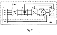
- a drive which comprises an converter-fed electric motor M, a rotation angle sensor D being provided on the rotor of the motor M.
- a rectifier G in particular a three-phase rectifier, is supplied from the AC network, i.e. by means of the mains supply N, the output-side unipolar voltage of which is smoothed by means of an intermediate circuit capacitor Z, to which the intermediate circuit voltage U_z is applied, which is a high voltage of up to 800 volts, for example.
- the rotation angle sensor D is located in the low-voltage range of the drive and is connected to ground potential.
- the power supply V for the electronic circuit arranged in the rotation angle sensor D separates the signal electronics and the rotation angle sensor D together with its electronic circuit from the high-voltage voltage.
- the rotation angle sensor is therefore preferably supplied from the secondary winding of a transformer, the primary winding of which is galvanically connected to the intermediate circuit, in particular to one of the intermediate circuit potentials.
- the signal transmission from the rotation angle sensor D to the signal electronics takes place without electrical isolation.
- the signal transmission of the control signals for the switches of the inverter are carried by the signal electronics to the switches of the inverter via the signal level converter P with electrical isolation.
- the inverter W feeding the motor is supplied from the intermediate circuit. It is controlled by the signal electronics with pulse-width-modulated control signals intended for its semiconductor switches in such a way that a three-phase voltage system is made available to the motor.
- the signal electronics comprise a controller, to which the detected rotation angle values and a detected motor current are fed.
- the controller On the output side, the controller provides values for output voltage, so that the pulse-width-modulated control signals can be generated accordingly, in particular taking into account the current intermediate circuit voltage.
- this insulation is also to be provided in the rotation angle sensor D.
- the signal electronics of the converter is therefore galvanically connected to a connection of the intermediate circuit capacitor, that is to say it is connected to the upper or lower intermediate circuit potential.
- the senor in particular its electronic circuit for generating the encoder signal and the associated signal conditioning, is also galvanically connected to an intermediate circuit potential, that is to say to a connection of the intermediate circuit capacitor. It is therefore at a high voltage potential compared to the PE or neutral conductor potential.
- an intermediate circuit potential that is to say to a connection of the intermediate circuit capacitor.
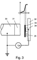
- FIG. 3 shows a schematic section for this.
- a shaft 30 of the motor in particular a metallic rotor shaft, is connected to ground via its bearing and has a measuring scale 31 at its axial end region.
- This measuring scale is preferably designed as a permanent magnet magnetized in the radial direction.
- a circuit board 32 on which sensors (34, 35) are provided, is arranged stationary opposite, in particular on the flange part or housing part of the motor.
- at least one sensor 34 in particular Wiegand sensor, and on the other hand at least one sensor 35, in particular Hall sensor, are provided.
- a cross-Hall sensor arranged centrally to the axis of the shaft is preferably used to detect the angular position.
- One or more pulse wire sensors that is to say Wiegand sensors, can be used to record the number of revolutions, so that even counting electronics can be supplied from the energy quantities of the pulses of the pulse wire sensors.
- An insulating means 33 is arranged between the printed circuit board 32 together with the components mounted on it and the shaft 30 together with the material measure 31, so that there is no electrical breakdown even at a short distance.
- the distance is so small that an electrical breakdown occurs when the insulating means 33 is omitted, since the potential difference between the high-voltage region and the low-voltage region is correspondingly large.
- the schematic course of the air gap potential is also indicated and shows the greater insulating strength of the insulating means 33 compared to the air
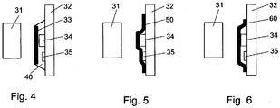
- the insulating medium is designed as a plate and is provided on an adhesive bed.
- the adhesive 40 is arranged between the circuit board 32 and the insulating means 33.
- the adhesive also acts as a potting compound, so that increased strength can be achieved for the entire arrangement or for the components, in particular sensors (34, 35), which are fitted on the printed circuit board.
- the insulating means 33 is designed as a rigid plate.
- FIG 5 Another embodiment is shown, in which, in contrast to Figure 4 the insulating means is designed as a flexible insulating plate 50, which lies on the surface of the adhesive 40 and partially follows it.
- the insulating means is designed as a preformed film, which in turn is glued to the printed circuit board 32 or is positively connected to the latter. When using adhesive 40, this is in turn arranged between the circuit board 32 and the preformed film.
- the insulating means is again in the form of a plate, in particular as a rigid plate, but potting compound 70 is provided on the circuit board in such a way that the insulating agent 33 is located within the potting compound, that is to say is potted.
- potting compound 70 is provided on the circuit board in such a way that the insulating agent 33 is located within the potting compound, that is to say is potted.
- Figure 8 is different from Figure 7 the insulating means is arranged on the surface of the potting compound 70, so that the insulating means is only partially potted, in particular on its side facing the printed circuit board 32.
- the plated-through holes used between the metallic layers 90 of the multilayer printed circuit board 32 are not contacted through the entire printed circuit board 32, that is to say they are only implemented as blind via 91 and thus only mediate a respective electrical contact between the regions to be electrically connected.
- the base material of the printed circuit board is thus used as an insulating means between the material measure 31 and electronic conductor tracks and components of the electronic circuit of the printed circuit board 32.
- the printed circuit board 32 faces the material measure Side metallic areas, especially where the areas form a regular grid.
- the printed circuit board 32 may be formed in one layer instead of in multiple layers.
- an insulating means is placed as a cap around the rotor shaft end with the measuring standard.
Landscapes
- Engineering & Computer Science (AREA)
- Power Engineering (AREA)
- Microelectronics & Electronic Packaging (AREA)
- Transmission And Conversion Of Sensor Element Output (AREA)
Claims (13)
- Entraînement, comprenant un moteur électrique alimenté par un variateur, sur lequel est disposé un capteur (35), en particulier un capteur d'angle de rotation, servant à déterminer la position angulaire d'un arbre (30), en particulier d'un arbre de rotor, du moteur électrique,
dans lequel le variateur présente une électronique de traitement de signaux, comprenant en particulier un régulateur, et une électronique de puissance comprenant un onduleur alimentant le moteur,
dans lequel l'onduleur est alimenté à partir d'une tension de circuit intermédiaire qui est en particulier supérieure à 50 volts ou supérieure à 100 volts,
dans lequel la tension de circuit intermédiaire alimente un condensateur de circuit intermédiaire ou une capacité de circuit intermédiaire correspondante, en particulier est lissée par lui ou par elle,
dans lequel le capteur (35) comprend un circuit électronique servant à générer des signaux de capteur avec traitement correspondant des signaux,
caractérisé en ce
que le circuit électronique du capteur (35) est relié galvaniquement à un potentiel de circuit intermédiaire de la tension de circuit intermédiaire, donc en particulier à une des bornes du condensateur de circuit intermédiaire ou d'une capacité de circuit intermédiaire correspondante,
une mesure matérialisée (31) étant disposée sur une zone d'extrémité axiale de l'arbre (30),
une carte de circuit imprimé (32) comprise par le circuit électronique du capteur (35) étant utilisée comme moyen d'isolement (33) pour l'isolement électrique entre la mesure matérialisée (31) et le capteur (35),
les composants (34, 35) du circuit électronique étant disposés du côté de la carte de circuit imprimé (32) opposé à la mesure matérialisée (31). - Entraînement selon au moins la revendication 1,
caractérisé en ce
que le capteur (35) est relié galvaniquement à l'électronique de traitement de signaux et/ou que
les signaux de capteur sont amenés à l'électronique de traitement de signaux directement, donc sans séparation galvanique. - Entraînement selon au moins l'une des revendications précédentes,
caractérisé en ce
que le capteur (35) est en liaison fonctionnelle avec la mesure matérialisée (31), en particulier détecte la mesure matérialisée (31), en particulier pour déterminer la position angulaire. - Entraînement selon au moins l'une des revendications précédentes,
caractérisé en ce
que la rigidité diélectrique du matériau du moyen d'isolement (33) est supérieure à 3 kV/mm et/ou à la rigidité diélectrique de l'air, en particulier de l'air ambiant sec à - 10 °C et à une pression de 1 bar. - Entraînement selon au moins l'une des revendications précédentes,
caractérisé en ce
que la carte de circuit imprimé (32) ne présente aucun trou métallisé traversant toute 1a carte de circuit imprimé (32), en particulier la carte de circuit imprimé (32) présentant donc seulement des vias borgnes (91) en tant que trous métallisés,
et/ou que la direction normale à la carte de circuit imprimé (32) est orientée dans la direction axiale de l'arbre,
et/ou que la carte de circuit imprimé (32) est réalisée sous forme monocouche ou multicouche, les couches étant prévues dans un matériau de base électriquement isolant. - Entraînement selon au moins l'une des revendications précédentes,
caractérisé en ce
que la carte de circuit imprimé (32) présente des zones métalliques (90) du côté tourné vers la mesure matérialisée (31), les zones (90) formant en particulier un réseau régulier. - Entraînement selon au moins l'une des revendications précédentes,
caractérisé en ce
qu'un moyen d'isolement (33), servant en particulier à l'isolement électrique, est relié de manière solidaire en rotation à la mesure matérialisée (31), le moyen d'isolement (33) étant en particulier relié à la mesure matérialisée (31) par coopération de matières, de forces et/ou de formes,
le moyen d'isolement (33) étant en particulier réalisé en forme de capot et/ou relié à la mesure matérialisée (31) par clipsage
et/ou le moyen d'isolement (33) étant étendu axialement de telle sorte qu'il recouvre au moins partiellement axialement la zone axiale recouverte par la mesure matérialisée (31),
l'axe de l'arbre définissant en particulier la direction axiale. - Entraînement selon au moins l'une des revendications précédentes,
caractérisé en ce
que la distance entre la mesure matérialisée (31) et le capteur (35) est assez petite et la capacité d'isolement et/ou la rigidité diélectrique du moyen d'isolement (33) assez élevée pour qu'un claquage électrique ait lieu ou du moins soit très probable en cas d'enlèvement du moyen d'isolement électrique (33). - Entraînement selon au moins l'une des revendications précédentes,
caractérisé en ce
qu'un moyen d'isolement supplémentaire est disposé sur ou dans une masse de scellement (70) et/ou sur ou dans une colle, la masse de scellement (70) ou la colle étant aussi reliée à une carte de circuit imprimé (32) du capteur (35) et/ou à des composants qui équipent la carte de circuit imprimé (32) du capteur (35),
le moyen d'isolement (33) étant en particulier réalisé dans un matériau qui présente une capacité d'isolement électrique plus élevée que l'air, en particulier au moins cinq fois plus élevée,
et/ou
qu'un moyen d'isolement supplémentaire est réalisé sous la forme d'une plaque rigide et/ou
qu'un moyen d'isolement supplémentaire est réalisé sous la forme d'une feuille (60) flexible, en particulier d'une feuille (60) autocollante, et recouvre au moins partiellement la carte de circuit imprimé (32) équipée de composants de son côté tourné vers la mesure matérialisée (31),
et/ou
qu'un moyen d'isolement supplémentaire est réalisé sous la forme d'une feuille (60) préformée, en particulier d'une feuille (60) autocollante, et recouvre au moins partiellement la carte de circuit imprimé (32) équipée de composants de son côté tourné vers la mesure matérialisée (31),
et/ou
qu'un moyen d'isolement supplémentaire est disposé entre la mesure matérialisée (31) et au moins une zone partielle de la colle ou de la masse de scellement (70). - Entraînement selon au moins l'une des revendications précédentes,
caractérisé en ce
que la mesure matérialisée (31) est un aimant permanent, en particulier un aimant permanent magnétisé en direction radiale. - Entraînement selon au moins l'une des revendications précédentes,
caractérisé en ce
que le capteur (35) comprend au moins un capteur à effet Hall (35) et/ou un capteur à effet Wiegand (35), le capteur (35) comprenant en particulier aussi un circuit d'évaluation servant à générer les signaux de capteur à partir des signaux de sortie du capteur à effet Wiegand et/ou du capteur à effet Hall (35). - Entraînement selon au moins l'une des revendications précédentes,
caractérisé en ce
qu'un redresseur du variateur est alimenté à partir d'une tension alternative du réseau et l'électronique de traitement de signaux est reliée galvaniquement à une sortie du redresseur et/ou l'électronique de traitement de signaux est reliée galvaniquement à un potentiel d'une tension unipolaire alimentant un onduleur du variateur et/ou d'une tension continue, en particulier de la tension de circuit intermédiaire. - Entraînement selon au moins l'une des revendications précédentes,
caractérisé en ce
que l'électronique de traitement de signaux génère des signaux de commande modulés en largeur d'impulsion pour des commutateurs à semi-conducteurs de l'onduleur, en tenant compte des signaux de capteur et/ou en tenant compte de l'allure des signaux de capteur.
Applications Claiming Priority (2)
| Application Number | Priority Date | Filing Date | Title |
|---|---|---|---|
| DE102010049681A DE102010049681A1 (de) | 2010-10-28 | 2010-10-28 | Antrieb |
| PCT/EP2011/005338 WO2012055521A2 (fr) | 2010-10-28 | 2011-10-24 | Entraînement |
Publications (3)
| Publication Number | Publication Date |
|---|---|
| EP2633618A2 EP2633618A2 (fr) | 2013-09-04 |
| EP2633618B1 EP2633618B1 (fr) | 2017-09-06 |
| EP2633618B2 true EP2633618B2 (fr) | 2020-05-27 |
Family
ID=45047704
Family Applications (1)
| Application Number | Title | Priority Date | Filing Date |
|---|---|---|---|
| EP11788362.9A Active EP2633618B2 (fr) | 2010-10-28 | 2011-10-24 | Entraînement |
Country Status (3)
| Country | Link |
|---|---|
| EP (1) | EP2633618B2 (fr) |
| DE (1) | DE102010049681A1 (fr) |
| WO (1) | WO2012055521A2 (fr) |
Families Citing this family (3)
| Publication number | Priority date | Publication date | Assignee | Title |
|---|---|---|---|---|
| US10439479B2 (en) * | 2015-01-23 | 2019-10-08 | Mitsubishi Electric Corporation | Electric drive device |
| US11139722B2 (en) | 2018-03-02 | 2021-10-05 | Black & Decker Inc. | Motor having an external heat sink for a power tool |
| US20220200401A1 (en) | 2020-12-23 | 2022-06-23 | Black & Decker Inc. | Brushless dc motor with circuit board for winding interconnections |
Citations (2)
| Publication number | Priority date | Publication date | Assignee | Title |
|---|---|---|---|---|
| EP1610095A1 (fr) † | 2004-06-21 | 2005-12-28 | HERA Rotterdam B.V. | Capteur de rotation pour déterminer la position angulaire absolue d'un arbre |
| DE102008037737A1 (de) † | 2007-08-28 | 2009-03-05 | Sew-Eurodrive Gmbh & Co. Kg | Elektromotor mit Winkelsensor |
Family Cites Families (5)
| Publication number | Priority date | Publication date | Assignee | Title |
|---|---|---|---|---|
| US6296065B1 (en) * | 1998-12-30 | 2001-10-02 | Black & Decker Inc. | Dual-mode non-isolated corded system for transportable cordless power tools |
| GB9924299D0 (en) * | 1999-10-15 | 1999-12-15 | Siemens Ag | Apparatus and method for measuring current |
| DE10207400B4 (de) | 2001-02-24 | 2019-03-14 | Marquardt Gmbh | Einrichtung zur Drehwinkeleinstellung |
| US7202619B1 (en) * | 2005-02-24 | 2007-04-10 | Gary Randolph Fisher | Variable frequency drive for AC synchronous motors with application to pumps |
| DE102007036271A1 (de) * | 2007-07-31 | 2009-02-05 | Baumer Hübner GmbH | Drehgeber mit Überwachung des Lagerverschleißes sowie Verfahren hierzu |
-
2010
- 2010-10-28 DE DE102010049681A patent/DE102010049681A1/de active Pending
-
2011
- 2011-10-24 EP EP11788362.9A patent/EP2633618B2/fr active Active
- 2011-10-24 WO PCT/EP2011/005338 patent/WO2012055521A2/fr not_active Ceased
Patent Citations (2)
| Publication number | Priority date | Publication date | Assignee | Title |
|---|---|---|---|---|
| EP1610095A1 (fr) † | 2004-06-21 | 2005-12-28 | HERA Rotterdam B.V. | Capteur de rotation pour déterminer la position angulaire absolue d'un arbre |
| DE102008037737A1 (de) † | 2007-08-28 | 2009-03-05 | Sew-Eurodrive Gmbh & Co. Kg | Elektromotor mit Winkelsensor |
Also Published As
| Publication number | Publication date |
|---|---|
| EP2633618A2 (fr) | 2013-09-04 |
| WO2012055521A3 (fr) | 2013-05-10 |
| EP2633618B1 (fr) | 2017-09-06 |
| DE102010049681A1 (de) | 2012-05-03 |
| WO2012055521A2 (fr) | 2012-05-03 |
Similar Documents
| Publication | Publication Date | Title |
|---|---|---|
| EP1906153B1 (fr) | Encodeur et son procédé de fonctionnement | |
| EP1422809B1 (fr) | Moteur électrique pour entraîner une pompe | |
| EP2863184B1 (fr) | Capteur de rotation avec alimentation autonome en énergie | |
| EP1160960B1 (fr) | Ensemble de moteur antidéflagrant | |
| EP2705413B1 (fr) | Système d'entraînement et procédé permettant de faire fonctionner un système d'entraînement | |
| EP2342148A1 (fr) | Entraînement de rouleaux et système d entraînements de rouleaux | |
| WO2015067497A2 (fr) | Machine électrique | |
| DE102010056120A1 (de) | Verschaltungseinrichtung für einen Elektromotor | |
| EP2542865B1 (fr) | Capteur de courant palier avec convertisseur d'énergie | |
| EP2633618B2 (fr) | Entraînement | |
| DE10362051B4 (de) | Elektromotor und Verfahren zur Herstellung | |
| WO2022136548A1 (fr) | Transformateur rotatif électrique destiné à la transmission inductive d'énergie | |
| EP3078112B1 (fr) | Actionneur avec capteur de position | |
| DE102014221015A1 (de) | Vorrichtung zum Betreiben eines Bremssystems eines Kraftfahrzeuges und Lagerotationssensor | |
| EP3452345B1 (fr) | Dispositif actionneur pour véhicule, système de freinage | |
| EP2689530B1 (fr) | Système d'entraînement et procédé de fonctionnement d'un système d'entraînement | |
| EP1452739B1 (fr) | Interface pour dispositif de commande d'une pompe | |
| DE102021212145B4 (de) | Elektrischer Drehtransformator zur induktiven Energieübertragung und fremderregte elektrische Synchronmaschine | |
| DE102010049682A1 (de) | Antrieb | |
| EP3475771B1 (fr) | Dispositif de commande de ventilateur à séparation de potentiel ainsi que système de ventilateurs et procédé de commande | |
| DE102009013374B4 (de) | Rotor für Elektromotoren, Permanentmagnet für einen solchen Rotor sowie elektrische Maschine mit einem Rotor | |
| DE102021103062A1 (de) | Stator | |
| DE102020203272A1 (de) | Motor | |
| EP3063505A1 (fr) | Capteur de position permettant de détecter une position d'un actionneur | |
| DE102023132281A1 (de) | Elektromotor-Anordnung |
Legal Events
| Date | Code | Title | Description |
|---|---|---|---|
| PUAI | Public reference made under article 153(3) epc to a published international application that has entered the european phase |
Free format text: ORIGINAL CODE: 0009012 |
|
| AK | Designated contracting states |
Kind code of ref document: A2 Designated state(s): AL AT BE BG CH CY CZ DE DK EE ES FI FR GB GR HR HU IE IS IT LI LT LU LV MC MK MT NL NO PL PT RO RS SE SI SK SM TR |
|
| AX | Request for extension of the european patent |
Extension state: BA ME |
|
| 17P | Request for examination filed |
Effective date: 20131111 |
|
| RBV | Designated contracting states (corrected) |
Designated state(s): AL AT BE BG CH CY CZ DE DK EE ES FI FR GB GR HR HU IE IS IT LI LT LU LV MC MK MT NL NO PL PT RO RS SE SI SK SM TR |
|
| DAX | Request for extension of the european patent (deleted) | ||
| GRAP | Despatch of communication of intention to grant a patent |
Free format text: ORIGINAL CODE: EPIDOSNIGR1 |
|
| INTG | Intention to grant announced |
Effective date: 20170425 |
|
| GRAS | Grant fee paid |
Free format text: ORIGINAL CODE: EPIDOSNIGR3 |
|
| GRAA | (expected) grant |
Free format text: ORIGINAL CODE: 0009210 |
|
| AK | Designated contracting states |
Kind code of ref document: B1 Designated state(s): AL AT BE BG CH CY CZ DE DK EE ES FI FR GB GR HR HU IE IS IT LI LT LU LV MC MK MT NL NO PL PT RO RS SE SI SK SM TR |
|
| REG | Reference to a national code |
Ref country code: GB Ref legal event code: FG4D Free format text: NOT ENGLISH |
|
| REG | Reference to a national code |
Ref country code: CH Ref legal event code: EP Ref country code: CH Ref legal event code: NV Representative=s name: HEPP WENGER RYFFEL AG, CH Ref country code: AT Ref legal event code: REF Ref document number: 926901 Country of ref document: AT Kind code of ref document: T Effective date: 20170915 |
|
| REG | Reference to a national code |
Ref country code: FR Ref legal event code: PLFP Year of fee payment: 7 |
|
| REG | Reference to a national code |
Ref country code: IE Ref legal event code: FG4D Free format text: LANGUAGE OF EP DOCUMENT: GERMAN |
|
| REG | Reference to a national code |
Ref country code: DE Ref legal event code: R096 Ref document number: 502011012971 Country of ref document: DE |
|
| REG | Reference to a national code |
Ref country code: NL Ref legal event code: MP Effective date: 20170906 |
|
| REG | Reference to a national code |
Ref country code: LT Ref legal event code: MG4D |
|
| PG25 | Lapsed in a contracting state [announced via postgrant information from national office to epo] |
Ref country code: HR Free format text: LAPSE BECAUSE OF FAILURE TO SUBMIT A TRANSLATION OF THE DESCRIPTION OR TO PAY THE FEE WITHIN THE PRESCRIBED TIME-LIMIT Effective date: 20170906 Ref country code: FI Free format text: LAPSE BECAUSE OF FAILURE TO SUBMIT A TRANSLATION OF THE DESCRIPTION OR TO PAY THE FEE WITHIN THE PRESCRIBED TIME-LIMIT Effective date: 20170906 Ref country code: LT Free format text: LAPSE BECAUSE OF FAILURE TO SUBMIT A TRANSLATION OF THE DESCRIPTION OR TO PAY THE FEE WITHIN THE PRESCRIBED TIME-LIMIT Effective date: 20170906 Ref country code: NO Free format text: LAPSE BECAUSE OF FAILURE TO SUBMIT A TRANSLATION OF THE DESCRIPTION OR TO PAY THE FEE WITHIN THE PRESCRIBED TIME-LIMIT Effective date: 20171206 Ref country code: SE Free format text: LAPSE BECAUSE OF FAILURE TO SUBMIT A TRANSLATION OF THE DESCRIPTION OR TO PAY THE FEE WITHIN THE PRESCRIBED TIME-LIMIT Effective date: 20170906 |
|
| PG25 | Lapsed in a contracting state [announced via postgrant information from national office to epo] |
Ref country code: BG Free format text: LAPSE BECAUSE OF FAILURE TO SUBMIT A TRANSLATION OF THE DESCRIPTION OR TO PAY THE FEE WITHIN THE PRESCRIBED TIME-LIMIT Effective date: 20171206 Ref country code: LV Free format text: LAPSE BECAUSE OF FAILURE TO SUBMIT A TRANSLATION OF THE DESCRIPTION OR TO PAY THE FEE WITHIN THE PRESCRIBED TIME-LIMIT Effective date: 20170906 Ref country code: ES Free format text: LAPSE BECAUSE OF FAILURE TO SUBMIT A TRANSLATION OF THE DESCRIPTION OR TO PAY THE FEE WITHIN THE PRESCRIBED TIME-LIMIT Effective date: 20170906 Ref country code: GR Free format text: LAPSE BECAUSE OF FAILURE TO SUBMIT A TRANSLATION OF THE DESCRIPTION OR TO PAY THE FEE WITHIN THE PRESCRIBED TIME-LIMIT Effective date: 20171207 Ref country code: RS Free format text: LAPSE BECAUSE OF FAILURE TO SUBMIT A TRANSLATION OF THE DESCRIPTION OR TO PAY THE FEE WITHIN THE PRESCRIBED TIME-LIMIT Effective date: 20170906 |
|
| PG25 | Lapsed in a contracting state [announced via postgrant information from national office to epo] |
Ref country code: NL Free format text: LAPSE BECAUSE OF FAILURE TO SUBMIT A TRANSLATION OF THE DESCRIPTION OR TO PAY THE FEE WITHIN THE PRESCRIBED TIME-LIMIT Effective date: 20170906 |
|
| PG25 | Lapsed in a contracting state [announced via postgrant information from national office to epo] |
Ref country code: RO Free format text: LAPSE BECAUSE OF FAILURE TO SUBMIT A TRANSLATION OF THE DESCRIPTION OR TO PAY THE FEE WITHIN THE PRESCRIBED TIME-LIMIT Effective date: 20170906 Ref country code: PL Free format text: LAPSE BECAUSE OF FAILURE TO SUBMIT A TRANSLATION OF THE DESCRIPTION OR TO PAY THE FEE WITHIN THE PRESCRIBED TIME-LIMIT Effective date: 20170906 Ref country code: CZ Free format text: LAPSE BECAUSE OF FAILURE TO SUBMIT A TRANSLATION OF THE DESCRIPTION OR TO PAY THE FEE WITHIN THE PRESCRIBED TIME-LIMIT Effective date: 20170906 |
|
| PG25 | Lapsed in a contracting state [announced via postgrant information from national office to epo] |
Ref country code: IS Free format text: LAPSE BECAUSE OF FAILURE TO SUBMIT A TRANSLATION OF THE DESCRIPTION OR TO PAY THE FEE WITHIN THE PRESCRIBED TIME-LIMIT Effective date: 20180106 Ref country code: SM Free format text: LAPSE BECAUSE OF FAILURE TO SUBMIT A TRANSLATION OF THE DESCRIPTION OR TO PAY THE FEE WITHIN THE PRESCRIBED TIME-LIMIT Effective date: 20170906 Ref country code: SK Free format text: LAPSE BECAUSE OF FAILURE TO SUBMIT A TRANSLATION OF THE DESCRIPTION OR TO PAY THE FEE WITHIN THE PRESCRIBED TIME-LIMIT Effective date: 20170906 Ref country code: IT Free format text: LAPSE BECAUSE OF FAILURE TO SUBMIT A TRANSLATION OF THE DESCRIPTION OR TO PAY THE FEE WITHIN THE PRESCRIBED TIME-LIMIT Effective date: 20170906 Ref country code: EE Free format text: LAPSE BECAUSE OF FAILURE TO SUBMIT A TRANSLATION OF THE DESCRIPTION OR TO PAY THE FEE WITHIN THE PRESCRIBED TIME-LIMIT Effective date: 20170906 |
|
| REG | Reference to a national code |
Ref country code: DE Ref legal event code: R026 Ref document number: 502011012971 Country of ref document: DE |
|
| PLBI | Opposition filed |
Free format text: ORIGINAL CODE: 0009260 |
|
| PLAX | Notice of opposition and request to file observation + time limit sent |
Free format text: ORIGINAL CODE: EPIDOSNOBS2 |
|
| PG25 | Lapsed in a contracting state [announced via postgrant information from national office to epo] |
Ref country code: MC Free format text: LAPSE BECAUSE OF FAILURE TO SUBMIT A TRANSLATION OF THE DESCRIPTION OR TO PAY THE FEE WITHIN THE PRESCRIBED TIME-LIMIT Effective date: 20170906 |
|
| 26 | Opposition filed |
Opponent name: LENZE DRIVES GMBH Effective date: 20180606 |
|
| REG | Reference to a national code |
Ref country code: IE Ref legal event code: MM4A |
|
| PG25 | Lapsed in a contracting state [announced via postgrant information from national office to epo] |
Ref country code: LU Free format text: LAPSE BECAUSE OF NON-PAYMENT OF DUE FEES Effective date: 20171024 Ref country code: DK Free format text: LAPSE BECAUSE OF FAILURE TO SUBMIT A TRANSLATION OF THE DESCRIPTION OR TO PAY THE FEE WITHIN THE PRESCRIBED TIME-LIMIT Effective date: 20170906 |
|
| REG | Reference to a national code |
Ref country code: BE Ref legal event code: MM Effective date: 20171031 |
|
| PLAS | Information related to reply of patent proprietor to notice(s) of opposition deleted |
Free format text: ORIGINAL CODE: EPIDOSDOBS3 |
|
| PLBB | Reply of patent proprietor to notice(s) of opposition received |
Free format text: ORIGINAL CODE: EPIDOSNOBS3 |
|
| PG25 | Lapsed in a contracting state [announced via postgrant information from national office to epo] |
Ref country code: SI Free format text: LAPSE BECAUSE OF FAILURE TO SUBMIT A TRANSLATION OF THE DESCRIPTION OR TO PAY THE FEE WITHIN THE PRESCRIBED TIME-LIMIT Effective date: 20170906 Ref country code: BE Free format text: LAPSE BECAUSE OF NON-PAYMENT OF DUE FEES Effective date: 20171031 |
|
| REG | Reference to a national code |
Ref country code: FR Ref legal event code: PLFP Year of fee payment: 8 |
|
| PG25 | Lapsed in a contracting state [announced via postgrant information from national office to epo] |
Ref country code: MT Free format text: LAPSE BECAUSE OF FAILURE TO SUBMIT A TRANSLATION OF THE DESCRIPTION OR TO PAY THE FEE WITHIN THE PRESCRIBED TIME-LIMIT Effective date: 20170906 |
|
| PG25 | Lapsed in a contracting state [announced via postgrant information from national office to epo] |
Ref country code: IE Free format text: LAPSE BECAUSE OF NON-PAYMENT OF DUE FEES Effective date: 20171024 |
|
| PG25 | Lapsed in a contracting state [announced via postgrant information from national office to epo] |
Ref country code: HU Free format text: LAPSE BECAUSE OF FAILURE TO SUBMIT A TRANSLATION OF THE DESCRIPTION OR TO PAY THE FEE WITHIN THE PRESCRIBED TIME-LIMIT; INVALID AB INITIO Effective date: 20111024 |
|
| PG25 | Lapsed in a contracting state [announced via postgrant information from national office to epo] |
Ref country code: CY Free format text: LAPSE BECAUSE OF NON-PAYMENT OF DUE FEES Effective date: 20170906 |
|
| PG25 | Lapsed in a contracting state [announced via postgrant information from national office to epo] |
Ref country code: MK Free format text: LAPSE BECAUSE OF FAILURE TO SUBMIT A TRANSLATION OF THE DESCRIPTION OR TO PAY THE FEE WITHIN THE PRESCRIBED TIME-LIMIT Effective date: 20170906 |
|
| PG25 | Lapsed in a contracting state [announced via postgrant information from national office to epo] |
Ref country code: TR Free format text: LAPSE BECAUSE OF FAILURE TO SUBMIT A TRANSLATION OF THE DESCRIPTION OR TO PAY THE FEE WITHIN THE PRESCRIBED TIME-LIMIT Effective date: 20170906 |
|
| PUAH | Patent maintained in amended form |
Free format text: ORIGINAL CODE: 0009272 |
|
| STAA | Information on the status of an ep patent application or granted ep patent |
Free format text: STATUS: PATENT MAINTAINED AS AMENDED |
|
| REG | Reference to a national code |
Ref country code: CH Ref legal event code: AELC |
|
| 27A | Patent maintained in amended form |
Effective date: 20200527 |
|
| AK | Designated contracting states |
Kind code of ref document: B2 Designated state(s): AL AT BE BG CH CY CZ DE DK EE ES FI FR GB GR HR HU IE IS IT LI LT LU LV MC MK MT NL NO PL PT RO RS SE SI SK SM TR |
|
| REG | Reference to a national code |
Ref country code: DE Ref legal event code: R102 Ref document number: 502011012971 Country of ref document: DE |
|
| PG25 | Lapsed in a contracting state [announced via postgrant information from national office to epo] |
Ref country code: PT Free format text: LAPSE BECAUSE OF FAILURE TO SUBMIT A TRANSLATION OF THE DESCRIPTION OR TO PAY THE FEE WITHIN THE PRESCRIBED TIME-LIMIT Effective date: 20170906 |
|
| PG25 | Lapsed in a contracting state [announced via postgrant information from national office to epo] |
Ref country code: AL Free format text: LAPSE BECAUSE OF FAILURE TO SUBMIT A TRANSLATION OF THE DESCRIPTION OR TO PAY THE FEE WITHIN THE PRESCRIBED TIME-LIMIT Effective date: 20170906 |
|
| PGFP | Annual fee paid to national office [announced via postgrant information from national office to epo] |
Ref country code: GB Payment date: 20250904 Year of fee payment: 15 |
|
| PGFP | Annual fee paid to national office [announced via postgrant information from national office to epo] |
Ref country code: FR Payment date: 20250908 Year of fee payment: 15 |
|
| REG | Reference to a national code |
Ref country code: CH Ref legal event code: U11 Free format text: ST27 STATUS EVENT CODE: U-0-0-U10-U11 (AS PROVIDED BY THE NATIONAL OFFICE) Effective date: 20251101 |
|
| PGFP | Annual fee paid to national office [announced via postgrant information from national office to epo] |
Ref country code: DE Payment date: 20251031 Year of fee payment: 15 |
|
| PGFP | Annual fee paid to national office [announced via postgrant information from national office to epo] |
Ref country code: AT Payment date: 20251009 Year of fee payment: 15 |
|
| PGFP | Annual fee paid to national office [announced via postgrant information from national office to epo] |
Ref country code: CH Payment date: 20251101 Year of fee payment: 15 |