EP2705764A2 - Système, dispositif d'envoi de tabac et procédé de transport de matériau de tabac humide broyé - Google Patents
Système, dispositif d'envoi de tabac et procédé de transport de matériau de tabac humide broyé Download PDFInfo
- Publication number
- EP2705764A2 EP2705764A2 EP13183014.3A EP13183014A EP2705764A2 EP 2705764 A2 EP2705764 A2 EP 2705764A2 EP 13183014 A EP13183014 A EP 13183014A EP 2705764 A2 EP2705764 A2 EP 2705764A2
- Authority
- EP
- European Patent Office
- Prior art keywords
- tobacco
- conveying
- conveying pipe
- negative pressure
- receiving device
- Prior art date
- Legal status (The legal status is an assumption and is not a legal conclusion. Google has not performed a legal analysis and makes no representation as to the accuracy of the status listed.)
- Withdrawn
Links
- 241000208125 Nicotiana Species 0.000 title claims abstract description 288
- 235000002637 Nicotiana tabacum Nutrition 0.000 title claims abstract description 288
- 239000000463 material Substances 0.000 title claims abstract description 81
- 238000000034 method Methods 0.000 title claims abstract description 16
- 238000011049 filling Methods 0.000 claims description 26
- 239000007788 liquid Substances 0.000 claims description 14
- 238000004140 cleaning Methods 0.000 claims description 11
- 238000011010 flushing procedure Methods 0.000 claims description 11
- 239000007921 spray Substances 0.000 claims description 9
- 238000003756 stirring Methods 0.000 claims description 8
- 238000001035 drying Methods 0.000 claims description 6
- 230000005484 gravity Effects 0.000 claims description 3
- 230000005540 biological transmission Effects 0.000 claims 1
- 238000010276 construction Methods 0.000 claims 1
- 239000003570 air Substances 0.000 description 29
- 210000000214 mouth Anatomy 0.000 description 4
- 238000004519 manufacturing process Methods 0.000 description 3
- NJPPVKZQTLUDBO-UHFFFAOYSA-N novaluron Chemical compound C1=C(Cl)C(OC(F)(F)C(OC(F)(F)F)F)=CC=C1NC(=O)NC(=O)C1=C(F)C=CC=C1F NJPPVKZQTLUDBO-UHFFFAOYSA-N 0.000 description 3
- 239000002351 wastewater Substances 0.000 description 3
- XLYOFNOQVPJJNP-UHFFFAOYSA-N water Substances O XLYOFNOQVPJJNP-UHFFFAOYSA-N 0.000 description 3
- 239000012080 ambient air Substances 0.000 description 2
- 239000000969 carrier Substances 0.000 description 2
- 125000004122 cyclic group Chemical group 0.000 description 2
- 230000002093 peripheral effect Effects 0.000 description 2
- 238000007790 scraping Methods 0.000 description 2
- 238000007789 sealing Methods 0.000 description 2
- 229910001220 stainless steel Inorganic materials 0.000 description 2
- 239000010935 stainless steel Substances 0.000 description 2
- NOOLISFMXDJSKH-UTLUCORTSA-N (+)-Neomenthol Chemical compound CC(C)[C@@H]1CC[C@@H](C)C[C@@H]1O NOOLISFMXDJSKH-UTLUCORTSA-N 0.000 description 1
- NLXLAEXVIDQMFP-UHFFFAOYSA-N Ammonia chloride Chemical compound [NH4+].[Cl-] NLXLAEXVIDQMFP-UHFFFAOYSA-N 0.000 description 1
- NOOLISFMXDJSKH-UHFFFAOYSA-N DL-menthol Natural products CC(C)C1CCC(C)CC1O NOOLISFMXDJSKH-UHFFFAOYSA-N 0.000 description 1
- 244000061176 Nicotiana tabacum Species 0.000 description 1
- 239000004698 Polyethylene Substances 0.000 description 1
- 239000000654 additive Substances 0.000 description 1
- 238000005054 agglomeration Methods 0.000 description 1
- 230000002776 aggregation Effects 0.000 description 1
- 235000019270 ammonium chloride Nutrition 0.000 description 1
- 229910000963 austenitic stainless steel Inorganic materials 0.000 description 1
- 235000019504 cigarettes Nutrition 0.000 description 1
- 230000003670 easy-to-clean Effects 0.000 description 1
- 238000000605 extraction Methods 0.000 description 1
- 239000000796 flavoring agent Substances 0.000 description 1
- 239000012530 fluid Substances 0.000 description 1
- 235000013355 food flavoring agent Nutrition 0.000 description 1
- 239000004615 ingredient Substances 0.000 description 1
- 238000011068 loading method Methods 0.000 description 1
- 229940041616 menthol Drugs 0.000 description 1
- 210000004400 mucous membrane Anatomy 0.000 description 1
- -1 polyethylene Polymers 0.000 description 1
- 229920000573 polyethylene Polymers 0.000 description 1
- 238000003672 processing method Methods 0.000 description 1
- 238000010926 purge Methods 0.000 description 1
- 238000000926 separation method Methods 0.000 description 1
- 239000000126 substance Substances 0.000 description 1
Images


Classifications
-
- A—HUMAN NECESSITIES
- A24—TOBACCO; CIGARS; CIGARETTES; SIMULATED SMOKING DEVICES; SMOKERS' REQUISITES
- A24C—MACHINES FOR MAKING CIGARS OR CIGARETTES
- A24C5/00—Making cigarettes; Making tipping materials for, or attaching filters or mouthpieces to, cigars or cigarettes
- A24C5/39—Tobacco feeding devices
- A24C5/392—Tobacco feeding devices feeding pneumatically
Definitions
- the invention relates to a system for conveying comminuted tobacco material having a moisture content of 35% or more, a tobacco dispenser and a method for conveying comminuted tobacco material having a moisture content of 35% or more.
- shredded tobacco material with a moisture content of 35% or more is meant in the context of the present application, in particular a ground or cut tobacco with a high moisture content.
- SNUS tobacco As a tobacco material thus ground or cut tobacco and possibly additives come into question.
- the cut length is so short that the cut moist tobacco material has a similar consistency as ground moist tobacco material.
- Such a moist ground or cut tobacco material Among other things, it is offered as so-called SNUS tobacco or smokeless tobacco and is used orally, ie in the oral cavity.
- SNUS tobacco has a moisture content of about 35% to 50% or more and is a fine-grained, lumpy substance that is similar in consistency to wet coffee grounds.
- SNUS tobacco is in some cases flavored with, for example, menthol, sal ammoniac or other flavoring agents, and is packaged in portions of 0.5 to 2 grams in so-called SNUS bags.
- This is a porous paper, the so-called “pouch”, which is completely sealed, but permeable to water and releases the ingredients of the "pouch” in the mouth and the mucous membranes of the mouth.
- the most common portion size is about one gram per serving. After consuming the "pouch" this is taken out of the mouth and disposed of.
- the moist, shredded tobacco material of SNUS tobacco clumps which requires special processing methods.
- the machines used to manufacture the SNUS pouches have hitherto been fed by hand with the shredded, moist tobacco material which has previously been kept refrigerated in containers in large refrigerated spaces.
- the containers in which the moist, shredded tobacco material is stored are covered so that the moisture of the tobacco material does not escape.
- care must be taken to ensure that the material does not dry out and heats up as little as possible.
- the present invention has the object to provide a system, system components and a method for conveying moist, shredded tobacco material available, with which the consistency of the wet tobacco material is maintained and an automatic promotion is possible without heavy burden on people.
- a system for conveying comminuted tobacco material with a moisture content of 35% or More comprising at least one tobacco end device and at least one tobacco receiving device, which are interconnected by means of at least one pressure-tight tobacco conveying tube, a control device and a controllable by the control device closure element, by means of which a connection of the tobacco end device to the tobacco conveyor tube is closable, and an air suction device, by means of which a negative pressure in the tobacco conveying pipe is producible, wherein the control device is designed to close the closure element to build up negative pressure in the tobacco conveying pipe and to open after the build-up of negative pressure for conveying tobacco material through the tobacco conveying pipe.
- the invention is based on the basic idea that a conveyor system for shredded tobacco material with a high moisture content provides a cyclically intermittent delivery of the moist, shredded tobacco material.
- one or more Tabaksendevoriquesen and one or more tobacco receiving devices are provided, which are interconnected by means of one or more pressure-tight tobacco delivery tubes.
- a negative pressure is built up in the tobacco-conveying tubes, for example between 100 hPa and 300 hPa, with no air flow occurring in the tobacco-conveying tube except for the air suction.
- the connection to the tobacco sending device is opened, so that wet, shredded tobacco material is sucked into the vacuum-loaded tobacco conveying tube and transported therethrough.
- the pressure equalization adjusts an air flow, which is directed by the tobacco end device in the direction of the tobacco receiving device. Because it is not a circulating airflow, as in others pneumatic conveying systems, this air flow is not heated, but corresponds to the ambient air, so that drying out of the moist tobacco material is effectively prevented.
- the tobacco material can travel a distance of several meters within the tobacco conveying tube, with very little material adhering and remaining to the tobacco conveying tube wall. The loss of tobacco material is thus minimal. This is also related to the intermittent mode of operation which minimizes agglomeration of material on the pipe wall by pressure surges and air ripples.
- the control device and the Laufabsaugvoraires cyclically alternately with a sealed connection between the tobacco dispenser and tobacco conveyor tube, the negative pressure in the tobacco conveyor tube generated and after reaching a preset or presettable negative pressure in the tobacco conveyor tube when opening the connection to the tobacco end delivery device, a pressure compensation with an air flow thrust to the tobacco receiving device can be generated.
- the preferred intermittent operation of the system is ensured by the control device and the Heilabsaugvorraum.
- the tobacco conveying tube preferably has a, in particular controllable, auxiliary air inlet in the region of the tobacco sending device. This ensures a precisely determinable air flow in the pressure equalization cycle, regardless of the filling of the tobacco dispenser with wet tobacco.
- the at least one tobacco receiving device has a pressure-tight sealable output.
- the pressure-tight lockable outlet also helps the system to adjust a negative pressure in the tobacco pipe.
- the wet, shredded tobacco material is separated from the air flow.
- This may be in the form of an air separator, for example a cyclone or a vacuum container, in which, for example, the tobacco material is pulled down by gravity while the air escapes in another direction, for example upwards.
- the at least one tobacco receiving device is part of a bag filling machine or for transferring received tobacco material to a bag filling machine at the bag filling machine and / or connected to the bag filling machine.
- the inventive system for conveying shredded, wet tobacco material is directly attached to a bagging machine that makes the commonly used sachets for, inter alia, SNUS tobacco, or part of the system is integrated into such a bag filling machine.
- a plurality of tobacco dispensing devices is connected to a plurality of tobacco receiving devices via a plurality of tobacco conveying tubes, or at least one tobacco dispensing device is connected to a plurality of tobacco receiving devices via a plurality of tobacco conveying tubes, in particular via a switch.
- a plurality of tobacco receiving devices may be charged from a large tobacco dispenser.
- an operator pedestal for manual filling is arranged on the tobacco end device and / or a lifting column trolley combination.
- the operator pedestal allows manual filling in which an operator, the operator, manually feeds the tobacco dispenser with the wet, shredded tobacco material.
- this can be supported by mechanical and motorized means such as lifting columns and trolleys, which can also be automated.
- the components, and in particular the tobacco conveying tube may consist of a brightly polished stainless steel, for example V4A stainless steel, which may be an austenitic stainless steel. This has very little affinity for attachment.
- the surfaces are preferably electropolished, therefore particularly smooth and bumpless.
- a flushing system is included, by means of which the at least one tobacco end device and / or the at least one tobacco conveying tube and / or the at least one tobacco receiving device can be flushed, the flushing system having a flushing liquid inlet and a flushing liquid outlet or flushing line, wherein spray nozzles, in particular 360 ° CIP nozzles are arranged or can be introduced in the tobacco dispenser and / or in the tobacco receiving device, wherein in particular further comprises a pipe cleaning plug for pipe cleaning and / or pipe drying and / or an electrically driven blower for drying is or are included.
- CIP nozzles are able to spray rinsing liquid, in particular warm water, in all directions to effectively clean an interior space. These spray nozzles allow automatic cleaning of the system.
- the spray nozzles in the tobacco or the tobacco end device (s) and / or in the or the tobacco receiving station (s) may be arranged.
- the tobacco receiving device can be connected or connectable to a rinsing line which can be acted upon by a negative pressure for the purpose of suctioning out rinsing liquid.
- a rinsing line which can be acted upon by a negative pressure for the purpose of suctioning out rinsing liquid.
- the suction can also be done separately from the tobacco dispenser and the tobacco receiving device.
- an electric blower can be used as a hair dryer to complete a cleaning process.
- a tobacco end device for conveying shredded tobacco material having a moisture content of 35% or more, wherein a gravitationally tapered funnel-shaped container is included, from above can be fed with tobacco material, wherein in the container a Rntonwerkstraverse is arranged with scrapers, which are directed against a funnel wall of the container, the container having at its lower end at least one tobacco outlet for connecting a pressure-tight tobacco conveying tube, in particular the scraper hinged to the Rrocktechnikstraverse below are arranged at an angle to the funnel wall, so that the scrapers when stirring by the resistance of the Tobacco material are pressed to the funnel wall.
- This tobacco dispenser according to the invention is suitable for vorzuuchzeln the wet, shredded tobacco material with its coffee grounds similar consistency by the tobacco material is stirred by scrapers and transported further and in particular is scraped off the funnel wall. Pulled by gravity, the tobacco material falls down in the direction of the connected tobacco conveyor tube.
- a sieve or a perforated plate is arranged in a lower part of the container and arranged the Rlickwerkstraverse with the scrapers above the screen or the perforated plate, wherein at least one scraper of Rlickwerkstraverse is directed against the sieve or the perforated plate, in particular the scraper hinged to the Agitator is arranged at an angle to the screen or the perforated plate, so that the scraper is pressed during stirring by the resistance of the tobacco material to the sieve or the perforated plate.
- the scrapers may for example consist of polyethylene.
- the tobacco dispenser according to the invention are preferably for cleaning the container spray nozzles, in particular 360 ° CIP nozzles, under a, in particular removable, lid arranged.
- the tobacco end device is easy to clean.
- This method according to the invention involves the cyclic alternation of generating negative pressure in the tobacco conveying tube and after reaching the desired negative pressure of a few hundred hPa below the ambient air pressure to establish a pressure equalization the opening of the connection between the tobacco dispenser and tobacco conveyor tube, whereby a compensating air suction, the tobacco material is created during pressure equalization in the tobacco conveyor tube from the tobacco dispenser in the tobacco conveyor tube in the direction entraining the tobacco receiving device.
- This also applies to the case where there are several tobacco-sending devices and / or several tobacco-receiving devices with corresponding tobacco-conveying tubes, for each tobacco-conveying tube individually.
- the tobacco material in the tobacco dispenser is loosened and / or singulated so far that it is entrained in one or more cycles of suction air in the tobacco conveying tube to the tobacco receiving device.
- the conveying method for the crushed wet tobacco material according to the present invention is directly connected to the filling into sachets.
- a plurality of tobacco conveying tubes can be operated independently of one another, or, in particular if there is only a small capacity for generating negative pressures, only one of a plurality of tobacco conveying tubes is opened to a tobacco sending device in each case.
- the first case assumes that the tobacco tubes are actually operated independently of each other and, for example, each have an air suction device available, while in the second case, for example, a Heilabsaugvorraum is used for air extraction in several different tobacco tubes.
- the measure of opening only one connection to a tobacco end device in each case ensures that the air suction device is used in each case only according to its capacity.
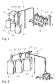
- a first variant of a system according to the invention for conveying moist comminuted tobacco material is shown.
- This system comprises three tobacco dispensers 10.1 to 10.3, each having a funnel-shaped container that tapers downwardly.
- Each of the tobacco dispensing devices 10.1 to 10.3 is connected to a respective tobacco conveying tube 12.1 to 12.3, which are guided in parallel over a distance.
- the three tobacco conveying pipes 12.1 to 12.3 are divided downstream and run to tobacco receiving devices 14.1 to 14.3, each of which is followed by a bag filling machine 16.1 to 16.3.
- the Tabaksendevoriquesen 10.1 to 10.3 are fed with wet shredded tobacco material, promote this towards the tobacco conveying pipes 12.1 to 12.3, through which they are conveyed to the tobacco receiving devices 14.1 to 14.3 by intermittent cyclic air ruptures, which prevent recapping of the tobacco material.
- the piping of the system 1 may be several tens of meters, for example up to 50 or 100 meters long.
- Fig. 1 To fill the Tabaksendevoriquesen 10.1 to 10.3 are two different ways in Fig. 1 shown. For a manual Filling is available to an operator an operator pedestal 18, which provides him access to the top of Tabaksendevoriquesen 10.1 to 10.3. For machine-assisted or automatic filling, a system of a trolley 19 mounted on a lifting column 20 is provided. The trolley 19 can be filled with tobacco and raised with the lifting column 20, wherein the trolley 19 is then emptied into the respective tobacco end device 10.1 to 10.3.
- a large tobacco-dispensing device 11 supplies three tobacco-receiving receiving devices 14.1 to 14.3 via three tobacco-conveying tubes 12.1 to 12.3, which can be configured as the tobacco-sending devices 14.1 to 14.3 and subsequently supplied with three bag filling machines 16.1 to 16.3.
- the tobacco conveying tubes 12.1 to 12.3 are guided parallel to a switch 13, in the switch 13 they then branch off to the various tobacco receiving devices 14.1 to 14.3 and bag filling machines 16.1 to 16.3.
- This system allows a large-volume feed of several tobacco receiving devices 14.1 to 14.3 from a single tobacco end device 11, while the system 1 of Fig. 1 For example, the promotion of different varieties of tobacco material allows.
- a tobacco dispenser 10 On a lower floor level, a hall floor 5, a tobacco dispenser 10 is positioned, which has a funnel-shaped container 30 which is placed on a tripod frame 31. On its upper side, the funnel-shaped container 30 has a lid 32 and a stirrer drive 34. The stirrer is in Fig. 3 not shown.
- the funnel-shaped container 30 merges into a tobacco outlet 36, which is connected via a controllable valve 38 to a tobacco conveying tube 12.
- the conveying direction is shown with arrows in the tobacco conveying pipe 12.
- the tobacco conveying pipe 12 terminates at a tobacco receiving device 14 which is mounted on a machine roof or a machine roof level 6.
- the tobacco receiving device 14 is designed in the form of a vacuum container 22 in which the tobacco material enters via a connecting piece for the tobacco conveying tube in a peripheral or tangential and slightly inclined manner.
- At the bottom of an outlet not shown in detail is arranged, through which the received tobacco material exits and passes to a bag filling machine, not shown.
- a vacuum line 26 sets, which is fed by a vacuum pump 24.
- a negative pressure is generated by means of the vacuum pump 24 in the vacuum container 22 and in the tobacco conveying pipe 12 when the controllable valve 38 is closed.
- the valve 38 is opened, the vacuum pump 24 can stop generating the negative pressure and by balancing the negative pressure creates an air flow from the tobacco outlet 36 of the tobacco dispenser 10 through the tobacco conveyor tube 12 into the vacuum container 22, by the reception of the Tobacco falls down and the air escapes.
- Fig. 4 shows the system 1 according to Fig. 3 during a rinse.
- a rinsing liquid for example, warm water
- a rinsing liquid for example, warm water
- the rinsing liquid collects in the funnel-shaped container 30
- the vacuum pump 24, the via a vacuum line 28 and a valve 29 is now connected to a mobile wastewater tank 42, employed in the mobile wastewater tank 42 generates a negative pressure and via a purge line 44, which is connected to the lower end of the vacuum container 22, the flushing liquid aspirated, including the rinsing liquid that has accumulated in the tobacco sending device 10.
- This can also be sucked through the tobacco conveyor tube 12, which is cleaned at the same time.
- a mechanical cleaning of the tobacco conveying pipe by means of a pipe cleaning plug can be done.
- an electrically driven blower can be used for drying.
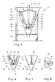
- Fig. 5 the funnel-shaped container 30 of the tobacco end device 10 is shown in cross-section.
- the funnel wall 33 extends from the top wide down to close.
- a stirring beam 130 is arranged, which has a central axis 131 around which the stirring beam 130 rotates. From the central axis 131, upper cantilever arms 132 and lower cantilever arms 133 branch off, holding the doctor beams 135, 136.
- the doctor carriers 135, 136 are rods whose inclination corresponds to the inclination of the funnel wall 33, and arranged at a defined distance from the funnel wall 33.
- Each of these scraper carriers 135, 136 carries a plurality of wall scrapers 137, the task of which is to remove moist comminuted tobacco material from the funnel wall 33 and allow it to trickle downwards.
- the stirring beam 130 has at its lower end a closure piece 134 which is aligned perpendicular to the central axis 131, and at which also the scraper carrier 135, 136 end.
- This end piece 134 also has a scraper, namely a screen scraper 138, which has an L-shaped surface.
- This screen scraper 138 sets with its lower scraper edge on a Sieve 35, which separates the interior, which separates with the stirring beam 130 from a lower cavity 37, followed by the tobacco outlet 36.
- the sieve 35 can also be designed as a perforated plate.
- the screen scraper 138 also has a shorter side piece which has a scraper edge scraping against the funnel wall 33.
- the screen 35 which may also be a perforated plate, in the direction of the tobacco outlet 36th
- Fig. 7 is the lower part according to Fig. 6 shown in a side cross-sectional view.
- a scraper holder 140 which is angled, wherein on the angled piece of screen scraper 138 is arranged, the scraper edge is also shown.
- the scraper edge is pressed against the screen 35.
- Two screen scrapers 138 can also be arranged on the two sides of the end piece 134.
- FIG. 3 is a partial top plan view of a portion of the funnel wall 33, together with a cross-section through a scraper carrier 135 on which a scraper holder 139 with a wall scraper 137 is disposed.
- the scraper holder 139 has an axis that allows easy rotation of the wall scraper 137 about the axis. Through the through the tobacco material the pressure exerted as the rotation traverse 130 rotates, the wall scraper 137 is pressed against the inner wall of the funnel wall 33 in this case as well.
- a tobacco receiving device 14 is shown schematically in cross-section.
- This is a vacuum container 22 having an upper part 52 and a lower part 50, which are connected to one another at a connection point by means of a connecting ring and a sealing ring or connected.
- a filter grid 68 and a perforated plate 70 which separate an upper subspace from a lower subspace.
- a 360 ° CIP spray nozzle 40 which serves to clean the vacuum tank 22, and connections 60 for compressed air, 62 for rinsing liquid and 58 for suction.
- a port 64 for a safety valve As in Fig. 9b ) is shown in plan view, there is also a port 64 for a safety valve.
- FIG. 9a illustrated lower subspace of the vacuum vessel 22 opens peripherally and in a direction obliquely downward pointing a port 66 for a tobacco pipe.
- a port 66 for a tobacco pipe As the air tobacco material stream from port 66 enters the vacuum vessel 22 tangentially, it acts substantially like a cyclone.
- a lock 72 With a gate valve 74, which is shown in a passage position and in a closed position one above the other. At any one time, only one of these two positions will be taken.
- the lock 74 is followed by a tobacco discharge funnel 76 through which received tobacco material to another station, such as a bag filling machine, is directed.
- FIG. 9c A perforated plate 70 is shown, which closes the upper part of the lower space of the vacuum chamber 22 and allows passage of air.
Landscapes
- Manufacture Of Tobacco Products (AREA)
- Manufacturing Of Cigar And Cigarette Tobacco (AREA)
Applications Claiming Priority (1)
| Application Number | Priority Date | Filing Date | Title |
|---|---|---|---|
| DE102012216031.0A DE102012216031B4 (de) | 2012-09-11 | 2012-09-11 | System, Tabaksendevorrichtung und Verfahren zum Fördern von feuchtem zerkleinerten Tabakmaterial |
Publications (2)
| Publication Number | Publication Date |
|---|---|
| EP2705764A2 true EP2705764A2 (fr) | 2014-03-12 |
| EP2705764A3 EP2705764A3 (fr) | 2014-05-07 |
Family
ID=49084904
Family Applications (1)
| Application Number | Title | Priority Date | Filing Date |
|---|---|---|---|
| EP13183014.3A Withdrawn EP2705764A3 (fr) | 2012-09-11 | 2013-09-04 | Système, dispositif d'envoi de tabac et procédé de transport de matériau de tabac humide broyé |
Country Status (2)
| Country | Link |
|---|---|
| EP (1) | EP2705764A3 (fr) |
| DE (1) | DE102012216031B4 (fr) |
Cited By (2)
| Publication number | Priority date | Publication date | Assignee | Title |
|---|---|---|---|---|
| CN115644489A (zh) * | 2022-10-11 | 2023-01-31 | 安徽中烟工业有限责任公司 | 一种卷烟烟草生产加工设备 |
| CN115813001A (zh) * | 2022-12-28 | 2023-03-21 | 河南中烟工业有限责任公司 | 高效传热烘丝机 |
Families Citing this family (3)
| Publication number | Priority date | Publication date | Assignee | Title |
|---|---|---|---|---|
| CN106628370A (zh) * | 2016-11-30 | 2017-05-10 | 芜湖立创包装有限公司 | 用于包装筒的加料装置 |
| CN106516256A (zh) * | 2016-11-30 | 2017-03-22 | 芜湖立创包装有限公司 | 用于包装筒的加料装置 |
| CN113197336A (zh) * | 2021-05-21 | 2021-08-03 | 河南中烟工业有限责任公司 | 烟丝输送装置 |
Citations (1)
| Publication number | Priority date | Publication date | Assignee | Title |
|---|---|---|---|---|
| WO1997033490A1 (fr) | 1996-03-15 | 1997-09-18 | Brown & Williamson Tobacco Corporation | Procede et appareil d'alimentation pneumatique automatique et continue en tabac |
Family Cites Families (10)
| Publication number | Priority date | Publication date | Assignee | Title |
|---|---|---|---|---|
| CH405241A (de) * | 1963-09-25 | 1966-01-15 | Oskar Krieger Fa | Abstreiferanordnung am rotierenden Rührwerk einer Mischvorrichtung |
| FR2213092A1 (en) * | 1973-01-09 | 1974-08-02 | Caillierez Francois | Pressure mixing vessel esp. for paint mfr. - offers improved process control of prod. density and viscosity |
| DE2445287C3 (de) * | 1974-09-21 | 1984-09-20 | Arthur Pfeiffer Vakuumtechnik Wetzlar Gmbh, 6334 Asslar | Vorrichtung zum Mischen und/oder Entgasen von hochviskosen Medien unter Vakuum |
| EP0135974A3 (fr) * | 1983-09-26 | 1986-06-11 | Thomassen & Drijver-Verblifa N.V. | Procédé pour le stockage étanche à l'air d'un produit non-gazeux dans un récipient, ce produit étant destiné à être enlevé par portions de ce récipient; dispositif pour la mise en oeuvre de ce procédé |
| DE9201929U1 (de) * | 1992-02-14 | 1992-04-16 | Hermann Waldner Gmbh & Co, 7988 Wangen | Abstreifer, insbesondere für Ankerrührwerk |
| IT1282436B1 (it) * | 1995-03-21 | 1998-03-23 | Tecnorama Srl | Variante del sistema di erogazione della apparecchiatura di dosaggio di materiali in polvere, granulati e microperle ed abbinamento di |
| ITBO20070688A1 (it) * | 2007-10-12 | 2009-04-13 | Azionaria Costruzioni Acma Spa | Macchina per la produzione di bustine contenenti una miscela di tabacco. |
| US8602068B2 (en) * | 2010-03-26 | 2013-12-10 | Philip Morris Usa Inc. | Method and apparatus for pouching tobacco having a high moisture content |
| GB201018292D0 (en) * | 2010-10-29 | 2010-12-15 | Fiedler & Lundgren Ab | Method and apparatus for production of smokeless tobacco products |
| EP2661183B1 (fr) * | 2011-01-07 | 2019-01-02 | Hauni Maschinenbau GmbH | Amenée de matériau de tabac broyé ou découpé à un dispositif de mise en portions |
-
2012
- 2012-09-11 DE DE102012216031.0A patent/DE102012216031B4/de not_active Expired - Fee Related
-
2013
- 2013-09-04 EP EP13183014.3A patent/EP2705764A3/fr not_active Withdrawn
Patent Citations (1)
| Publication number | Priority date | Publication date | Assignee | Title |
|---|---|---|---|---|
| WO1997033490A1 (fr) | 1996-03-15 | 1997-09-18 | Brown & Williamson Tobacco Corporation | Procede et appareil d'alimentation pneumatique automatique et continue en tabac |
Cited By (3)
| Publication number | Priority date | Publication date | Assignee | Title |
|---|---|---|---|---|
| CN115644489A (zh) * | 2022-10-11 | 2023-01-31 | 安徽中烟工业有限责任公司 | 一种卷烟烟草生产加工设备 |
| CN115813001A (zh) * | 2022-12-28 | 2023-03-21 | 河南中烟工业有限责任公司 | 高效传热烘丝机 |
| CN115813001B (zh) * | 2022-12-28 | 2025-09-16 | 河南中烟工业有限责任公司 | 高效传热烘丝机 |
Also Published As
| Publication number | Publication date |
|---|---|
| EP2705764A3 (fr) | 2014-05-07 |
| DE102012216031B4 (de) | 2017-01-26 |
| DE102012216031A1 (de) | 2014-03-13 |
Similar Documents
| Publication | Publication Date | Title |
|---|---|---|
| EP2785594B1 (fr) | Machine d'emballage et procédé de remplissage de sacs | |
| DE102012216031B4 (de) | System, Tabaksendevorrichtung und Verfahren zum Fördern von feuchtem zerkleinerten Tabakmaterial | |
| EP3010812A1 (fr) | Machine d'emballage et procédé | |
| DE2802265A1 (de) | Verfahren und vorrichtung zum entlueften von pulver, beispielsweise milchpulver, das in ein behaeltnis, beispielsweise einen beutel eingefuellt wird | |
| EP1162909A1 (fr) | Procede permettant de vider un contenant fixe a ou dans un aspirateur ainsi que contenant, aspirateur pourvu du contenant et systeme collecteur de poussiere destine a la mise en oeuvre du procede | |
| DE102016101027B4 (de) | Rundläufertablettenpresse | |
| EP3552716A1 (fr) | Dispositif de transport destiné au transport de la poudre de revêtement, centre d'alimentation en poudre pourvu d'appareil de transport et procédé de nettoyage du centre d'alimentation en poudre | |
| WO2003022718A1 (fr) | Dispositif et procede pour transporter un produit a transporter de type poussiere, poudre, grains ou granules, d'un recipient de stockage dans un recipient de travail ou de transport ou dans un espace de reception de meme type | |
| EP3552714A1 (fr) | Transporteur de poudre destiné à transporter le poudre de revêtement, méthode de fabriquation de transportateur et centre d'alimentation en poudre pourvu de transporteur de poudre destiné à alimenter un centre d'alimentation en poudre | |
| DE102019121594A1 (de) | Anschlussvorrichtung | |
| EP2613893B1 (fr) | Système de nettoyage de contenants et procédé de nettoyage | |
| EP2052976B1 (fr) | Dispositif de fabrication de sachets d'infusion | |
| DE19602443C2 (de) | Dosiervorrichtung, insbesondere für pulver- oder partikelförmige Reinigungsmittel | |
| WO2013079136A1 (fr) | Système et procédé de séparation de cellules | |
| DE4343443C2 (de) | Verfahren und Vorrichtung zum Dosieren von saugbaren Stoffen | |
| DE102006032184B4 (de) | Vorrichtung zum Fördern pulverförmiger fluidisierter Medien | |
| EP2228305B1 (fr) | Methode pour remplir un récipient avec des particules de glace carbonique. | |
| DE3127481A1 (de) | Vorrichtung zum entleeren von dragierkesseln und zum nachtrocknen und zwischenlagern von dragees | |
| DE2403091C2 (de) | Vorrichtung zum Aussieben von Schmutzteilchen aus einem feinkörnigen, pneumatisch geförderten Schüttgut | |
| EP2777465B1 (fr) | Machine de nettoyage du sol dotée d'un tuyau d'aspiration manuel | |
| DE10234013A1 (de) | Vorrichtung und Verfahren zum Überführen eines staub-,pulver,korn-oder granulatartigen Fördergutes aus einem Lagerbehälter in einen Arbeits-oder Überführungsbehälter od.dgl. Aufnahmeraum | |
| DE19634291C2 (de) | Vorrichtung zum Sieben | |
| DE10117770A1 (de) | Vorrichtung zum Absacken von Schüttgut | |
| DE4203495A1 (de) | Sackentleervorrichtung und verfahren zum betrieb und reinigen derselben | |
| DE2934242C2 (de) | Staubabsaugeinrichtung an einer Zellenrad-Blasversatzmaschine |
Legal Events
| Date | Code | Title | Description |
|---|---|---|---|
| PUAI | Public reference made under article 153(3) epc to a published international application that has entered the european phase |
Free format text: ORIGINAL CODE: 0009012 |
|
| AK | Designated contracting states |
Kind code of ref document: A2 Designated state(s): AL AT BE BG CH CY CZ DE DK EE ES FI FR GB GR HR HU IE IS IT LI LT LU LV MC MK MT NL NO PL PT RO RS SE SI SK SM TR |
|
| AX | Request for extension of the european patent |
Extension state: BA ME |
|
| PUAL | Search report despatched |
Free format text: ORIGINAL CODE: 0009013 |
|
| AK | Designated contracting states |
Kind code of ref document: A3 Designated state(s): AL AT BE BG CH CY CZ DE DK EE ES FI FR GB GR HR HU IE IS IT LI LT LU LV MC MK MT NL NO PL PT RO RS SE SI SK SM TR |
|
| AX | Request for extension of the european patent |
Extension state: BA ME |
|
| RIC1 | Information provided on ipc code assigned before grant |
Ipc: A24C 5/39 20060101AFI20140401BHEP |
|
| 17P | Request for examination filed |
Effective date: 20141016 |
|
| RBV | Designated contracting states (corrected) |
Designated state(s): AL AT BE BG CH CY CZ DE DK EE ES FI FR GB GR HR HU IE IS IT LI LT LU LV MC MK MT NL NO PL PT RO RS SE SI SK SM TR |
|
| RAP1 | Party data changed (applicant data changed or rights of an application transferred) |
Owner name: HAUNI MASCHINENBAU GMBH |
|
| GRAP | Despatch of communication of intention to grant a patent |
Free format text: ORIGINAL CODE: EPIDOSNIGR1 |
|
| INTG | Intention to grant announced |
Effective date: 20170706 |
|
| STAA | Information on the status of an ep patent application or granted ep patent |
Free format text: STATUS: THE APPLICATION IS DEEMED TO BE WITHDRAWN |
|
| 18D | Application deemed to be withdrawn |
Effective date: 20171117 |