EP2705929A1 - Système d'ajustement pour un système de transfert dans un système de diagnostic in vitro - Google Patents
Système d'ajustement pour un système de transfert dans un système de diagnostic in vitro Download PDFInfo
- Publication number
- EP2705929A1 EP2705929A1 EP12183261.2A EP12183261A EP2705929A1 EP 2705929 A1 EP2705929 A1 EP 2705929A1 EP 12183261 A EP12183261 A EP 12183261A EP 2705929 A1 EP2705929 A1 EP 2705929A1
- Authority
- EP
- European Patent Office
- Prior art keywords
- adjustment
- contact element
- adjustment system
- transfer
- vitro diagnostic
- Prior art date
- Legal status (The legal status is an assumption and is not a legal conclusion. Google has not performed a legal analysis and makes no representation as to the accuracy of the status listed.)
- Granted
Links
Images

Classifications
-
- G—PHYSICS
- G01—MEASURING; TESTING
- G01B—MEASURING LENGTH, THICKNESS OR SIMILAR LINEAR DIMENSIONS; MEASURING ANGLES; MEASURING AREAS; MEASURING IRREGULARITIES OF SURFACES OR CONTOURS
- G01B21/00—Measuring arrangements or details thereof, where the measuring technique is not covered by the other groups of this subclass, unspecified or not relevant
- G01B21/16—Measuring arrangements or details thereof, where the measuring technique is not covered by the other groups of this subclass, unspecified or not relevant for measuring distance of clearance between spaced objects
-
- G—PHYSICS
- G01—MEASURING; TESTING
- G01N—INVESTIGATING OR ANALYSING MATERIALS BY DETERMINING THEIR CHEMICAL OR PHYSICAL PROPERTIES
- G01N35/00—Automatic analysis not limited to methods or materials provided for in any single one of groups G01N1/00 - G01N33/00; Handling materials therefor
- G01N35/10—Devices for transferring samples or any liquids to, in, or from, the analysis apparatus, e.g. suction devices, injection devices
-
- G—PHYSICS
- G01—MEASURING; TESTING
- G01N—INVESTIGATING OR ANALYSING MATERIALS BY DETERMINING THEIR CHEMICAL OR PHYSICAL PROPERTIES
- G01N35/00—Automatic analysis not limited to methods or materials provided for in any single one of groups G01N1/00 - G01N33/00; Handling materials therefor
- G01N35/10—Devices for transferring samples or any liquids to, in, or from, the analysis apparatus, e.g. suction devices, injection devices
- G01N35/1081—Devices for transferring samples or any liquids to, in, or from, the analysis apparatus, e.g. suction devices, injection devices characterised by the means for relatively moving the transfer device and the containers in an horizontal plane
- G01N35/109—Devices for transferring samples or any liquids to, in, or from, the analysis apparatus, e.g. suction devices, injection devices characterised by the means for relatively moving the transfer device and the containers in an horizontal plane with two horizontal degrees of freedom
Definitions
- the invention relates to an adjustment system for a transfer system in an in vitro diagnostic system, wherein the adjustment system comprises a contact element, which is arranged on a movable element of the transfer system.
- Today's devices are capable of performing a variety of detection reactions and analyzes with a sample.
- such in vitro diagnostic systems usually comprise a receiving position for a reaction vessel and an analysis system associated with the receiving position.
- the sample vessel is usually transported several times to different addition and / or reaction stations.
- automatic analyzers have transfer systems, ie devices for the spatial transfer of the vessels, such as transfer arms, conveyor belts, rotatable transport wheels or plates.
- the device comprises a control unit, which is by means of appropriate software in a position to plan the work steps for the desired analysis largely independently and work off.
- a corresponding sensor on the drive of each movable element to be adjusted of the transfer system e.g. on a part of a transfer arm, which transmits to the control unit information about the current position of the drive.
- the transfer arm is then controlled by the control unit to move to an alignment mark.
- Hitherto known adjustment systems often operate on a capacitive basis, wherein a needle is guided on the movable element on a small metal surface on the alignment mark as the contact element. If a touch is detected, the control unit saves the corresponding position of the drive.
- the object of the present invention is to provide an adjustment system which allows faster automated adjustment of transfer systems in an in vitro diagnostic system.
- the contact element is arranged by means of a hinge member on the movable member, wherein the hinge element is configured self-restoring, and wherein a distance between the contact element and the movable element is associated with a distance measuring sensor.
- the invention has the advantage that a faster automated adjustment of transfer systems in an in vitro diagnostic system is possible if the adjustment without rigid and relatively sensitive components such as in particular the previously used needles for capacitive Measurement gets along.
- the contact element is mounted on a movable element of the transfer system and configured self-restoring, ie the joint develops restoring forces, for example by springs or other elastic components during a deflection from a defined rest position, a contact can be determined by the deflection of the contact element and the joint ,
- a distance measuring sensor is assigned to a distance between the contact element and the movable element.
- the distance measuring sensor by no means must be able to determine a continuously correct absolute size for the distance, but a simple determination of a relative change in the distance is sufficient.
- a deflection from the rest position in fact, a touch of a defined alignment mark in the in-vitro diagnostic system can already be detected and a position adjustment can thus be carried out.
- the distance measuring sensor comprises a Hall sensor and a magnet.
- the magnet is attached to one of the components and the Hall sensor to the other component.
- a change in the relative position of the magnet to the Hall sensor causes a change in the generated magnetic field in the Hall sensor and thus allows contact detection of the contact element on an alignment mark. Due to the self-resetting properties of the joint element of the magnet is always without touching the contact element at the same distance from the Hall sensor, so that here always the same magnetic field is applied.
- a magnetic distance sensor has the advantage over the capacitive, especially that it is particularly resistant to external influences by electromagnetic fields of e.g. Is mobile phones.
- the Hall sensor is arranged on the movable element and the magnet on the contact element.
- the structure for distance measurement is symmetrically interchangeable.
- the magnet is only a passive element, while the Hall sensor is the active, signal-producing element. Because the signals anyway passed through the movable element and its drive in the control unit, such an attachment shortens the signal paths and simplifies the construction.
- the joint element is designed for a multi-dimensional movement. This results in a considerable simplification of the adjustment, since the adjustment can be performed with the same contact element in each spatial direction.
- the direction of movement of the joint changes upon contact of the contact element with a Justagemarker depending on the direction of approach. With the contact, however, in each case a change in distance is connected, to which the distance measuring sensor responds.
- the joint element comprises a rubber compound, which connects the contact element and the movable element.
- rubber combines advantageous properties: The joint is durable and less maintenance-prone, the rubber allows movement in any dimension and moves independently due to its elasticity in the rest position.
- a transfer system typically has a functional device, which is typically arranged at the end of the transfer arm and is configured differently depending on the specific use of the transfer arm.
- This functional device is advantageously arranged on the contact element.
- the contact element On the one hand, this increases the accuracy of the adjustment, since the functional device is precisely the component of the transfer system, which interacts with other components of the in vitro diagnostic system and therefore has to be precisely adjusted.
- the self-return joint element acts as a spring for the functional device, which may be desired in interaction with other components of the in vitro diagnostic system.
- the functional device comprises a gripping device for gripping sample or reagent vessels and / or a pipetting device for transporting liquids.
- the functional device is arranged with respect to the joint element on a side facing away from the distance measuring sensor.
- the contact element acts practically as a lever over the joint element.
- the distance of the distance measuring sensor can be increased by the joint element, which also increases the deflection of the distance measuring sensor. This improves the accuracy of the measurement.
- a transfer system for an in vitro diagnostic system advantageously comprises a described adjustment system.
- An automated in vitro diagnostic system also advantageously comprises such a transfer system and / or a described adjustment system.
- the advantages achieved by the invention are, in particular, that small mechanical movements in all three dimensions can be detected by the use of a mounted via a joint contact element with a distance measuring sensor and thus a faster and more accurate adjustment is possible.
- no manual adjustment is necessary.
- the device can automatically capture the current state and use the factors found immediately without the need for user assistance. There is no restriction on the direction of movement, since an adjustment in all three spatial directions is possible.
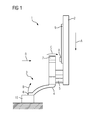
- FIG. 1 shows a schematic representation of a transfer system 1 in the form of a transfer arm in an in vitro diagnostic system, not shown.
- the transfer system 1 comprises a movable element 2, which can be moved freely by a drive, not shown.
- the control of the movable element is controlled by a control unit, also not shown.
- the drive has corresponding sensors which provide the control unit with information about the current position of the drive.
- an adjustment system 3 which comprises a contact element 4, which is attached by means of a hinge element 5 to the movable element 2 of the transfer system 1.
- the joint element 5 consists of two rubber blocks which connect the contact element 4 and the movable element 2 at a distance. The joint element 5 thus enables a multi-dimensional movement of contact element 4 and movable element 2 against each other, but automatically returns to the rest position.
- a magnet 7 is arranged at the contact element 4 designed as a cuvette function device 6 at the contact element 4 designed as a cuvette function device 6 at the contact element 4 designed as a cuvette function device 6 at the contact element 4 designed as a cuvette function device 6 at the contact element 4 designed as a cuvette function device 6 at the contact element 4 designed as a cuvette function device 6 at the contact element 4 designed as a cuvette function device 6 at the contact element 4 designed as a cuvette function device 6 is arranged. This serves to grasp sample or reagent vessels. By means of the transfer system 1, these are then transported within the in vitro diagnostic system.
- a magnet 7 is arranged at the of the Function device 6 remote end of the contact element 4.
- the magnet 7 is assigned a Hall sensor 8 on a printed circuit board 9 in the opposite region on the movable element 2.
- the Hall sensor 8 detects changes in the relative position of the magnet 7 in each direction by the change of the magnetic field and supplies this information via the circuit board 9 to the control unit. Magnet 7 and Hall sensor 8 thus
- the adjustment is carried out by the contact element 4 is guided to an alignment mark 10.
- the transfer system is moved in the direction of A.
- the contact element 4 abuts with the functional device 6 on the alignment mark 10.
- the contact element 4 executes an evasive movement B.
- the magnet 7 in the contact element 4 and the Hall sensor 8 have a certain distance.
- the evasive movement of the contact element 4 results in a change in this distance, represented by the movement C.
- the magnetic field strength measured by the Hall sensor 8 changes.
- the position of the alignment mark 10 is thus recognized and is evaluated by the control unit for adjustment.
- FIG. 2 shows the transfer system 1 from FIG. 1 from the direction R, shown in FIG. 1 in a semitransparent representation. All components off FIG. 1 are also shown here, but shows FIG. 2 that an adjustment in other spatial directions is possible.
- the direction of the movement to the alignment mark 10 is again shown as movement A, wherein the movement A is now perpendicular to the movement A in FIG. 1 stands. Adjustment is also possible in this direction without changing the adjustment system 3, represented by movements B and C.
Landscapes
- Physics & Mathematics (AREA)
- General Physics & Mathematics (AREA)
- Health & Medical Sciences (AREA)
- Life Sciences & Earth Sciences (AREA)
- Chemical & Material Sciences (AREA)
- Analytical Chemistry (AREA)
- Biochemistry (AREA)
- General Health & Medical Sciences (AREA)
- Immunology (AREA)
- Pathology (AREA)
- Automatic Analysis And Handling Materials Therefor (AREA)
Priority Applications (4)
| Application Number | Priority Date | Filing Date | Title |
|---|---|---|---|
| EP12183261.2A EP2705929B1 (fr) | 2012-09-06 | 2012-09-06 | Système d'ajustement pour un système de transfert dans un système de diagnostic in vitro |
| ES12183261T ES2875039T3 (es) | 2012-09-06 | 2012-09-06 | Sistema de ajuste para un sistema de transferencia en un sistema de diagnóstico in vitro |
| US13/971,280 US9372080B2 (en) | 2012-09-06 | 2013-08-20 | Adjustment system for a transfer system in an in-vitro diagnostics system |
| JP2013185145A JP6304977B2 (ja) | 2012-09-06 | 2013-09-06 | インビトロ診断システム |
Applications Claiming Priority (1)
| Application Number | Priority Date | Filing Date | Title |
|---|---|---|---|
| EP12183261.2A EP2705929B1 (fr) | 2012-09-06 | 2012-09-06 | Système d'ajustement pour un système de transfert dans un système de diagnostic in vitro |
Publications (2)
| Publication Number | Publication Date |
|---|---|
| EP2705929A1 true EP2705929A1 (fr) | 2014-03-12 |
| EP2705929B1 EP2705929B1 (fr) | 2021-04-14 |
Family
ID=47172262
Family Applications (1)
| Application Number | Title | Priority Date | Filing Date |
|---|---|---|---|
| EP12183261.2A Active EP2705929B1 (fr) | 2012-09-06 | 2012-09-06 | Système d'ajustement pour un système de transfert dans un système de diagnostic in vitro |
Country Status (4)
| Country | Link |
|---|---|
| US (1) | US9372080B2 (fr) |
| EP (1) | EP2705929B1 (fr) |
| JP (1) | JP6304977B2 (fr) |
| ES (1) | ES2875039T3 (fr) |
Cited By (1)
| Publication number | Priority date | Publication date | Assignee | Title |
|---|---|---|---|---|
| EP3220148A1 (fr) * | 2016-03-17 | 2017-09-20 | Siemens Healthcare Diagnostics Products GmbH | Procede de surveillance du transport de conteneurs de liquides dans un appareil d'analyse automatique |
Families Citing this family (6)
| Publication number | Priority date | Publication date | Assignee | Title |
|---|---|---|---|---|
| EP3096148B1 (fr) * | 2015-05-20 | 2024-01-03 | Siemens Healthcare Diagnostics Products GmbH | Dispositif de pipetage |
| EP3196649B1 (fr) * | 2016-01-22 | 2021-08-18 | Siemens Healthcare Diagnostics Products GmbH | Systeme d'ajustement |
| EP3417266B1 (fr) | 2016-02-19 | 2024-08-07 | Siemens Healthcare Diagnostics Inc. | Structure de bras de transfert monobloc et pince de montage pour instrumentation analytique |
| US11372014B2 (en) * | 2016-05-12 | 2022-06-28 | Siemens Healthcare Diagnostics Inc. | Clinical analyzer probe crash detection mechanism and process |
| JP6734989B2 (ja) * | 2016-07-21 | 2020-08-05 | シーメンス・ヘルスケア・ダイアグノスティックス・インコーポレーテッドSiemens Healthcare Diagnostics Inc. | オートメーショントラックのモニタリング及びメンテナンスに基づいて調節するシステム及び方法 |
| EP3293524B1 (fr) * | 2016-09-12 | 2021-06-09 | Stratec SE | Couplage fluidique |
Citations (4)
| Publication number | Priority date | Publication date | Assignee | Title |
|---|---|---|---|---|
| CH414798A (de) * | 1960-09-22 | 1966-06-15 | Siemens Ag | Kontaktloser Befehlsgeber |
| US3819888A (en) * | 1973-02-26 | 1974-06-25 | Cutler Hammer Inc | Limit switch mechanism |
| US20030054543A1 (en) * | 1997-06-16 | 2003-03-20 | Lafferty William Michael | Device for moving a selected station of a holding plate to a predetermined location for interaction with a probe |
| US20100176806A1 (en) * | 2008-03-25 | 2010-07-15 | O'day Richard | Absolute Position Sensing |
Family Cites Families (15)
| Publication number | Priority date | Publication date | Assignee | Title |
|---|---|---|---|---|
| JPS61275660A (ja) * | 1985-05-31 | 1986-12-05 | Hitachi Ltd | サンプリング装置 |
| JP2524728B2 (ja) * | 1987-01-16 | 1996-08-14 | 和光純薬工業株式会社 | 透過光測定装置 |
| EP0555739B1 (fr) * | 1992-02-13 | 1998-05-20 | F. Hoffmann-La Roche Ag | Dispositif automatique de pipettage |
| US5273717A (en) * | 1992-09-30 | 1993-12-28 | Eastman Kodak Company | Self-calibrating analyzer aspirator |
| US5512247A (en) * | 1994-05-02 | 1996-04-30 | Hoffmann-La Roche Inc. | Apparatus for testing pipetting needle linearity in an automated analyzer |
| JP3765255B2 (ja) * | 2001-08-21 | 2006-04-12 | 株式会社日立製作所 | 攪拌装置およびそれを用いた自動分析装置 |
| JP4156822B2 (ja) * | 2001-09-11 | 2008-09-24 | アロカ株式会社 | ハンドリング装置 |
| JP2003344427A (ja) * | 2002-05-22 | 2003-12-03 | Aloka Co Ltd | 分注装置 |
| JP4355682B2 (ja) * | 2005-06-16 | 2009-11-04 | アロカ株式会社 | 自動分注装置及び自動分注方法 |
| JP4646311B2 (ja) * | 2005-11-22 | 2011-03-09 | 株式会社スギノマシン | ノズル先端基準高さ位置調整装置及びサンプリング装置 |
| JP5157950B2 (ja) * | 2009-02-05 | 2013-03-06 | 横河電機株式会社 | 分注装置 |
| JP5275182B2 (ja) * | 2009-09-11 | 2013-08-28 | 株式会社日立ハイテクノロジーズ | 分注装置及び分析装置 |
| DE102009048918A1 (de) * | 2009-10-10 | 2011-04-14 | Siemens Healthcare Diagnostics Products Gmbh | Vorrichtung zum Mischen einer Flüssigkeitsprobe |
| EP2752668A3 (fr) * | 2010-07-23 | 2014-10-15 | Beckman Coulter, Inc. | Système ou procédé comprenant des unités analytiques |
| JP5371905B2 (ja) * | 2010-07-30 | 2013-12-18 | シスメックス株式会社 | 検体処理装置の管理システム、検体処理装置及び管理装置ならびに管理方法 |
-
2012
- 2012-09-06 EP EP12183261.2A patent/EP2705929B1/fr active Active
- 2012-09-06 ES ES12183261T patent/ES2875039T3/es active Active
-
2013
- 2013-08-20 US US13/971,280 patent/US9372080B2/en active Active
- 2013-09-06 JP JP2013185145A patent/JP6304977B2/ja active Active
Patent Citations (4)
| Publication number | Priority date | Publication date | Assignee | Title |
|---|---|---|---|---|
| CH414798A (de) * | 1960-09-22 | 1966-06-15 | Siemens Ag | Kontaktloser Befehlsgeber |
| US3819888A (en) * | 1973-02-26 | 1974-06-25 | Cutler Hammer Inc | Limit switch mechanism |
| US20030054543A1 (en) * | 1997-06-16 | 2003-03-20 | Lafferty William Michael | Device for moving a selected station of a holding plate to a predetermined location for interaction with a probe |
| US20100176806A1 (en) * | 2008-03-25 | 2010-07-15 | O'day Richard | Absolute Position Sensing |
Cited By (1)
| Publication number | Priority date | Publication date | Assignee | Title |
|---|---|---|---|---|
| EP3220148A1 (fr) * | 2016-03-17 | 2017-09-20 | Siemens Healthcare Diagnostics Products GmbH | Procede de surveillance du transport de conteneurs de liquides dans un appareil d'analyse automatique |
Also Published As
| Publication number | Publication date |
|---|---|
| ES2875039T3 (es) | 2021-11-08 |
| JP6304977B2 (ja) | 2018-04-04 |
| JP2014052376A (ja) | 2014-03-20 |
| US20140065017A1 (en) | 2014-03-06 |
| US9372080B2 (en) | 2016-06-21 |
| EP2705929B1 (fr) | 2021-04-14 |
Similar Documents
| Publication | Publication Date | Title |
|---|---|---|
| EP2705929B1 (fr) | Système d'ajustement pour un système de transfert dans un système de diagnostic in vitro | |
| EP3452833B1 (fr) | Procédé pour déterminer la position d'un bras robotisé dans un système de manipulation de liquide et système de manipulation de liquide correspondant | |
| EP0816831B1 (fr) | Dispositif pour l'évaluation de bandes de test | |
| EP3112861B1 (fr) | Procédé de détection de contact d'une aiguille de pipetage | |
| EP3096148B1 (fr) | Dispositif de pipetage | |
| EP3025780B1 (fr) | Plateau d'incubation | |
| WO2013153048A1 (fr) | Unité de commande pour un appareil de véhicule | |
| WO2018091122A1 (fr) | Console de commande portative robotisée, dispositif d'accouplement associé, robot et procédé | |
| EP2917684A1 (fr) | Dispositif et procédé de mesure permettant de mesurer l'épaisseur d'un objet en forme de plaque | |
| DE102013225463A1 (de) | Bedienvorrichtung für ein elektrisches Gerät oder eine Anlage, insbesondere für eine Fahrzeugkomponente | |
| EP2793031B1 (fr) | Système de pipetage pour un appareil d'analyse | |
| EP3216517A1 (fr) | Procede de melange d'un liquide dans un appareil d'analyse automatique | |
| EP2977767B1 (fr) | Dispositif de détermination de position d'une jauge mobile automatique | |
| EP2633624B1 (fr) | Dispositif électronique et procédé de mise en service d'un dispositif électronique | |
| EP2955526A1 (fr) | Dispositif de détermination de la position d'une jauge et procédé de détermination de la position | |
| EP3316078B1 (fr) | Procédé de fonctionnement d'une unité de mesure et unité de mesure | |
| EP3196649B1 (fr) | Systeme d'ajustement | |
| DE102016123122B3 (de) | Haptic-Test-Messvorrichtung und Verfahren zur Ermittlung einer Kraft-Weg-Kurve bei einer Haptic-Test-Messung | |
| EP2693943B1 (fr) | Système d'analyse avec dispositif de mesure et élément d'essai | |
| DE102013205305A1 (de) | Vorrichtung zur Einstellung eines Betriebsparameters einer elektrischen Einrichtung | |
| EP3173794B1 (fr) | Procede de transfert d'un volume de liquide dans un appareil d'analyse | |
| DE102020105496B4 (de) | Verstellvorrichtung für ein Kraftfahrzeug | |
| EP3220148B1 (fr) | Procede de surveillance du transport de conteneurs de liquides dans un appareil d'analyse automatique | |
| DE102020119883B4 (de) | Prüfvorrichtung zum Überprüfen einer Anordnung einer Bohrung, Stanzmutteranordnungsvorrichtung, Verfahren zum Überprüfen der Anordnung der Bohrung, und Steuereinrichtung | |
| WO2021224123A1 (fr) | Dispositif de préhension pour le transfert d'un barreau dipôle magnétique |
Legal Events
| Date | Code | Title | Description |
|---|---|---|---|
| PUAI | Public reference made under article 153(3) epc to a published international application that has entered the european phase |
Free format text: ORIGINAL CODE: 0009012 |
|
| AK | Designated contracting states |
Kind code of ref document: A1 Designated state(s): AL AT BE BG CH CY CZ DE DK EE ES FI FR GB GR HR HU IE IS IT LI LT LU LV MC MK MT NL NO PL PT RO RS SE SI SK SM TR |
|
| AX | Request for extension of the european patent |
Extension state: BA ME |
|
| 17P | Request for examination filed |
Effective date: 20140805 |
|
| RBV | Designated contracting states (corrected) |
Designated state(s): AL AT BE BG CH CY CZ DE DK EE ES FI FR GB GR HR HU IE IS IT LI LT LU LV MC MK MT NL NO PL PT RO RS SE SI SK SM TR |
|
| STAA | Information on the status of an ep patent application or granted ep patent |
Free format text: STATUS: EXAMINATION IS IN PROGRESS |
|
| 17Q | First examination report despatched |
Effective date: 20190618 |
|
| GRAP | Despatch of communication of intention to grant a patent |
Free format text: ORIGINAL CODE: EPIDOSNIGR1 |
|
| STAA | Information on the status of an ep patent application or granted ep patent |
Free format text: STATUS: GRANT OF PATENT IS INTENDED |
|
| INTG | Intention to grant announced |
Effective date: 20210122 |
|
| RIN1 | Information on inventor provided before grant (corrected) |
Inventor name: HERZ, ACHIM Inventor name: WIEDEKIND-KLEIN, ALEXANDER |
|
| GRAS | Grant fee paid |
Free format text: ORIGINAL CODE: EPIDOSNIGR3 |
|
| GRAA | (expected) grant |
Free format text: ORIGINAL CODE: 0009210 |
|
| STAA | Information on the status of an ep patent application or granted ep patent |
Free format text: STATUS: THE PATENT HAS BEEN GRANTED |
|
| AK | Designated contracting states |
Kind code of ref document: B1 Designated state(s): AL AT BE BG CH CY CZ DE DK EE ES FI FR GB GR HR HU IE IS IT LI LT LU LV MC MK MT NL NO PL PT RO RS SE SI SK SM TR |
|
| REG | Reference to a national code |
Ref country code: GB Ref legal event code: FG4D Free format text: NOT ENGLISH |
|
| REG | Reference to a national code |
Ref country code: CH Ref legal event code: EP |
|
| REG | Reference to a national code |
Ref country code: CH Ref legal event code: NV Representative=s name: SIEMENS SCHWEIZ AG, CH |
|
| REG | Reference to a national code |
Ref country code: DE Ref legal event code: R096 Ref document number: 502012016721 Country of ref document: DE |
|
| REG | Reference to a national code |
Ref country code: IE Ref legal event code: FG4D Free format text: LANGUAGE OF EP DOCUMENT: GERMAN |
|
| REG | Reference to a national code |
Ref country code: AT Ref legal event code: REF Ref document number: 1381892 Country of ref document: AT Kind code of ref document: T Effective date: 20210515 |
|
| REG | Reference to a national code |
Ref country code: SE Ref legal event code: TRGR |
|
| REG | Reference to a national code |
Ref country code: LT Ref legal event code: MG9D |
|
| REG | Reference to a national code |
Ref country code: NL Ref legal event code: MP Effective date: 20210414 |
|
| PG25 | Lapsed in a contracting state [announced via postgrant information from national office to epo] |
Ref country code: LT Free format text: LAPSE BECAUSE OF FAILURE TO SUBMIT A TRANSLATION OF THE DESCRIPTION OR TO PAY THE FEE WITHIN THE PRESCRIBED TIME-LIMIT Effective date: 20210414 Ref country code: NL Free format text: LAPSE BECAUSE OF FAILURE TO SUBMIT A TRANSLATION OF THE DESCRIPTION OR TO PAY THE FEE WITHIN THE PRESCRIBED TIME-LIMIT Effective date: 20210414 Ref country code: FI Free format text: LAPSE BECAUSE OF FAILURE TO SUBMIT A TRANSLATION OF THE DESCRIPTION OR TO PAY THE FEE WITHIN THE PRESCRIBED TIME-LIMIT Effective date: 20210414 Ref country code: HR Free format text: LAPSE BECAUSE OF FAILURE TO SUBMIT A TRANSLATION OF THE DESCRIPTION OR TO PAY THE FEE WITHIN THE PRESCRIBED TIME-LIMIT Effective date: 20210414 Ref country code: BG Free format text: LAPSE BECAUSE OF FAILURE TO SUBMIT A TRANSLATION OF THE DESCRIPTION OR TO PAY THE FEE WITHIN THE PRESCRIBED TIME-LIMIT Effective date: 20210714 |
|
| REG | Reference to a national code |
Ref country code: ES Ref legal event code: FG2A Ref document number: 2875039 Country of ref document: ES Kind code of ref document: T3 Effective date: 20211108 |
|
| PG25 | Lapsed in a contracting state [announced via postgrant information from national office to epo] |
Ref country code: GR Free format text: LAPSE BECAUSE OF FAILURE TO SUBMIT A TRANSLATION OF THE DESCRIPTION OR TO PAY THE FEE WITHIN THE PRESCRIBED TIME-LIMIT Effective date: 20210715 Ref country code: LV Free format text: LAPSE BECAUSE OF FAILURE TO SUBMIT A TRANSLATION OF THE DESCRIPTION OR TO PAY THE FEE WITHIN THE PRESCRIBED TIME-LIMIT Effective date: 20210414 Ref country code: IS Free format text: LAPSE BECAUSE OF FAILURE TO SUBMIT A TRANSLATION OF THE DESCRIPTION OR TO PAY THE FEE WITHIN THE PRESCRIBED TIME-LIMIT Effective date: 20210814 Ref country code: RS Free format text: LAPSE BECAUSE OF FAILURE TO SUBMIT A TRANSLATION OF THE DESCRIPTION OR TO PAY THE FEE WITHIN THE PRESCRIBED TIME-LIMIT Effective date: 20210414 Ref country code: NO Free format text: LAPSE BECAUSE OF FAILURE TO SUBMIT A TRANSLATION OF THE DESCRIPTION OR TO PAY THE FEE WITHIN THE PRESCRIBED TIME-LIMIT Effective date: 20210714 Ref country code: PL Free format text: LAPSE BECAUSE OF FAILURE TO SUBMIT A TRANSLATION OF THE DESCRIPTION OR TO PAY THE FEE WITHIN THE PRESCRIBED TIME-LIMIT Effective date: 20210414 Ref country code: PT Free format text: LAPSE BECAUSE OF FAILURE TO SUBMIT A TRANSLATION OF THE DESCRIPTION OR TO PAY THE FEE WITHIN THE PRESCRIBED TIME-LIMIT Effective date: 20210816 |
|
| REG | Reference to a national code |
Ref country code: DE Ref legal event code: R097 Ref document number: 502012016721 Country of ref document: DE |
|
| PG25 | Lapsed in a contracting state [announced via postgrant information from national office to epo] |
Ref country code: CZ Free format text: LAPSE BECAUSE OF FAILURE TO SUBMIT A TRANSLATION OF THE DESCRIPTION OR TO PAY THE FEE WITHIN THE PRESCRIBED TIME-LIMIT Effective date: 20210414 Ref country code: DK Free format text: LAPSE BECAUSE OF FAILURE TO SUBMIT A TRANSLATION OF THE DESCRIPTION OR TO PAY THE FEE WITHIN THE PRESCRIBED TIME-LIMIT Effective date: 20210414 Ref country code: EE Free format text: LAPSE BECAUSE OF FAILURE TO SUBMIT A TRANSLATION OF THE DESCRIPTION OR TO PAY THE FEE WITHIN THE PRESCRIBED TIME-LIMIT Effective date: 20210414 Ref country code: SM Free format text: LAPSE BECAUSE OF FAILURE TO SUBMIT A TRANSLATION OF THE DESCRIPTION OR TO PAY THE FEE WITHIN THE PRESCRIBED TIME-LIMIT Effective date: 20210414 Ref country code: SK Free format text: LAPSE BECAUSE OF FAILURE TO SUBMIT A TRANSLATION OF THE DESCRIPTION OR TO PAY THE FEE WITHIN THE PRESCRIBED TIME-LIMIT Effective date: 20210414 Ref country code: RO Free format text: LAPSE BECAUSE OF FAILURE TO SUBMIT A TRANSLATION OF THE DESCRIPTION OR TO PAY THE FEE WITHIN THE PRESCRIBED TIME-LIMIT Effective date: 20210414 |
|
| PLBE | No opposition filed within time limit |
Free format text: ORIGINAL CODE: 0009261 |
|
| STAA | Information on the status of an ep patent application or granted ep patent |
Free format text: STATUS: NO OPPOSITION FILED WITHIN TIME LIMIT |
|
| 26N | No opposition filed |
Effective date: 20220117 |
|
| REG | Reference to a national code |
Ref country code: BE Ref legal event code: MM Effective date: 20210930 |
|
| PG25 | Lapsed in a contracting state [announced via postgrant information from national office to epo] |
Ref country code: IS Free format text: LAPSE BECAUSE OF FAILURE TO SUBMIT A TRANSLATION OF THE DESCRIPTION OR TO PAY THE FEE WITHIN THE PRESCRIBED TIME-LIMIT Effective date: 20210814 Ref country code: MC Free format text: LAPSE BECAUSE OF FAILURE TO SUBMIT A TRANSLATION OF THE DESCRIPTION OR TO PAY THE FEE WITHIN THE PRESCRIBED TIME-LIMIT Effective date: 20210414 Ref country code: AL Free format text: LAPSE BECAUSE OF FAILURE TO SUBMIT A TRANSLATION OF THE DESCRIPTION OR TO PAY THE FEE WITHIN THE PRESCRIBED TIME-LIMIT Effective date: 20210414 |
|
| PG25 | Lapsed in a contracting state [announced via postgrant information from national office to epo] |
Ref country code: LU Free format text: LAPSE BECAUSE OF NON-PAYMENT OF DUE FEES Effective date: 20210906 Ref country code: IE Free format text: LAPSE BECAUSE OF NON-PAYMENT OF DUE FEES Effective date: 20210906 Ref country code: BE Free format text: LAPSE BECAUSE OF NON-PAYMENT OF DUE FEES Effective date: 20210930 |
|
| REG | Reference to a national code |
Ref country code: AT Ref legal event code: MM01 Ref document number: 1381892 Country of ref document: AT Kind code of ref document: T Effective date: 20210906 |
|
| PG25 | Lapsed in a contracting state [announced via postgrant information from national office to epo] |
Ref country code: AT Free format text: LAPSE BECAUSE OF NON-PAYMENT OF DUE FEES Effective date: 20210906 |
|
| PGFP | Annual fee paid to national office [announced via postgrant information from national office to epo] |
Ref country code: ES Payment date: 20221216 Year of fee payment: 11 |
|
| PG25 | Lapsed in a contracting state [announced via postgrant information from national office to epo] |
Ref country code: HU Free format text: LAPSE BECAUSE OF FAILURE TO SUBMIT A TRANSLATION OF THE DESCRIPTION OR TO PAY THE FEE WITHIN THE PRESCRIBED TIME-LIMIT; INVALID AB INITIO Effective date: 20120906 Ref country code: CY Free format text: LAPSE BECAUSE OF FAILURE TO SUBMIT A TRANSLATION OF THE DESCRIPTION OR TO PAY THE FEE WITHIN THE PRESCRIBED TIME-LIMIT Effective date: 20210414 |
|
| PGFP | Annual fee paid to national office [announced via postgrant information from national office to epo] |
Ref country code: IT Payment date: 20230920 Year of fee payment: 12 |
|
| PGFP | Annual fee paid to national office [announced via postgrant information from national office to epo] |
Ref country code: SE Payment date: 20230911 Year of fee payment: 12 |
|
| PG25 | Lapsed in a contracting state [announced via postgrant information from national office to epo] |
Ref country code: MK Free format text: LAPSE BECAUSE OF FAILURE TO SUBMIT A TRANSLATION OF THE DESCRIPTION OR TO PAY THE FEE WITHIN THE PRESCRIBED TIME-LIMIT Effective date: 20210414 |
|
| PG25 | Lapsed in a contracting state [announced via postgrant information from national office to epo] |
Ref country code: TR Free format text: LAPSE BECAUSE OF FAILURE TO SUBMIT A TRANSLATION OF THE DESCRIPTION OR TO PAY THE FEE WITHIN THE PRESCRIBED TIME-LIMIT Effective date: 20210414 |
|
| PG25 | Lapsed in a contracting state [announced via postgrant information from national office to epo] |
Ref country code: MT Free format text: LAPSE BECAUSE OF FAILURE TO SUBMIT A TRANSLATION OF THE DESCRIPTION OR TO PAY THE FEE WITHIN THE PRESCRIBED TIME-LIMIT Effective date: 20210414 |
|
| REG | Reference to a national code |
Ref country code: ES Ref legal event code: FD2A Effective date: 20241025 |
|
| PG25 | Lapsed in a contracting state [announced via postgrant information from national office to epo] |
Ref country code: ES Free format text: LAPSE BECAUSE OF NON-PAYMENT OF DUE FEES Effective date: 20230907 |
|
| PG25 | Lapsed in a contracting state [announced via postgrant information from national office to epo] |
Ref country code: ES Free format text: LAPSE BECAUSE OF NON-PAYMENT OF DUE FEES Effective date: 20230907 |
|
| REG | Reference to a national code |
Ref country code: SE Ref legal event code: EUG |
|
| PG25 | Lapsed in a contracting state [announced via postgrant information from national office to epo] |
Ref country code: IT Free format text: LAPSE BECAUSE OF NON-PAYMENT OF DUE FEES Effective date: 20240906 |
|
| PG25 | Lapsed in a contracting state [announced via postgrant information from national office to epo] |
Ref country code: SE Free format text: LAPSE BECAUSE OF NON-PAYMENT OF DUE FEES Effective date: 20240907 |
|
| PGFP | Annual fee paid to national office [announced via postgrant information from national office to epo] |
Ref country code: FR Payment date: 20250915 Year of fee payment: 14 |
|
| REG | Reference to a national code |
Ref country code: CH Ref legal event code: U11 Free format text: ST27 STATUS EVENT CODE: U-0-0-U10-U11 (AS PROVIDED BY THE NATIONAL OFFICE) Effective date: 20251210 |
|
| PGFP | Annual fee paid to national office [announced via postgrant information from national office to epo] |
Ref country code: DE Payment date: 20251120 Year of fee payment: 14 |
|
| PGFP | Annual fee paid to national office [announced via postgrant information from national office to epo] |
Ref country code: GB Payment date: 20251002 Year of fee payment: 14 |
|
| PGFP | Annual fee paid to national office [announced via postgrant information from national office to epo] |
Ref country code: CH Payment date: 20251210 Year of fee payment: 14 |