EP2706020B1 - Récipient pour fil de soudage avec deux éléments de maintien superposés - Google Patents
Récipient pour fil de soudage avec deux éléments de maintien superposés Download PDFInfo
- Publication number
- EP2706020B1 EP2706020B1 EP12183193.7A EP12183193A EP2706020B1 EP 2706020 B1 EP2706020 B1 EP 2706020B1 EP 12183193 A EP12183193 A EP 12183193A EP 2706020 B1 EP2706020 B1 EP 2706020B1
- Authority
- EP
- European Patent Office
- Prior art keywords
- retainer
- wire
- hollow body
- previous
- container according
- Prior art date
- Legal status (The legal status is an assumption and is not a legal conclusion. Google has not performed a legal analysis and makes no representation as to the accuracy of the status listed.)
- Not-in-force
Links
- 238000003466 welding Methods 0.000 title claims description 56
- 230000002093 peripheral effect Effects 0.000 claims description 23
- 238000000034 method Methods 0.000 claims description 9
- 239000000463 material Substances 0.000 claims description 7
- 238000004806 packaging method and process Methods 0.000 claims description 4
- 238000010891 electric arc Methods 0.000 claims description 3
- 239000011248 coating agent Substances 0.000 description 3
- 238000000576 coating method Methods 0.000 description 3
- 238000000605 extraction Methods 0.000 description 3
- 239000002184 metal Substances 0.000 description 3
- 229910052751 metal Inorganic materials 0.000 description 3
- 239000002023 wood Substances 0.000 description 3
- 230000007547 defect Effects 0.000 description 2
- 230000004907 flux Effects 0.000 description 2
- 239000010410 layer Substances 0.000 description 2
- 238000004519 manufacturing process Methods 0.000 description 2
- 230000010355 oscillation Effects 0.000 description 2
- 239000000123 paper Substances 0.000 description 2
- RYGMFSIKBFXOCR-UHFFFAOYSA-N Copper Chemical compound [Cu] RYGMFSIKBFXOCR-UHFFFAOYSA-N 0.000 description 1
- 230000015572 biosynthetic process Effects 0.000 description 1
- 230000000052 comparative effect Effects 0.000 description 1
- 239000002131 composite material Substances 0.000 description 1
- 229910052802 copper Inorganic materials 0.000 description 1
- 239000010949 copper Substances 0.000 description 1
- 230000007423 decrease Effects 0.000 description 1
- 238000009826 distribution Methods 0.000 description 1
- 230000000694 effects Effects 0.000 description 1
- 238000005755 formation reaction Methods 0.000 description 1
- 230000001788 irregular Effects 0.000 description 1
- 238000002844 melting Methods 0.000 description 1
- 230000008018 melting Effects 0.000 description 1
- 229920000642 polymer Polymers 0.000 description 1
- 239000002861 polymer material Substances 0.000 description 1
- 239000007787 solid Substances 0.000 description 1
- 238000003860 storage Methods 0.000 description 1
- 239000002344 surface layer Substances 0.000 description 1
- 238000005493 welding type Methods 0.000 description 1
Images


Classifications
-
- B—PERFORMING OPERATIONS; TRANSPORTING
- B65—CONVEYING; PACKING; STORING; HANDLING THIN OR FILAMENTARY MATERIAL
- B65D—CONTAINERS FOR STORAGE OR TRANSPORT OF ARTICLES OR MATERIALS, e.g. BAGS, BARRELS, BOTTLES, BOXES, CANS, CARTONS, CRATES, DRUMS, JARS, TANKS, HOPPERS, FORWARDING CONTAINERS; ACCESSORIES, CLOSURES, OR FITTINGS THEREFOR; PACKAGING ELEMENTS; PACKAGES
- B65D85/00—Containers, packaging elements or packages, specially adapted for particular articles or materials
- B65D85/02—Containers, packaging elements or packages, specially adapted for particular articles or materials for annular articles
- B65D85/04—Containers, packaging elements or packages, specially adapted for particular articles or materials for annular articles for coils of wire, rope or hose
-
- B—PERFORMING OPERATIONS; TRANSPORTING
- B65—CONVEYING; PACKING; STORING; HANDLING THIN OR FILAMENTARY MATERIAL
- B65H—HANDLING THIN OR FILAMENTARY MATERIAL, e.g. SHEETS, WEBS, CABLES
- B65H49/00—Unwinding or paying-out filamentary material; Supporting, storing or transporting packages from which filamentary material is to be withdrawn or paid-out
- B65H49/02—Methods or apparatus in which packages do not rotate
- B65H49/04—Package-supporting devices
- B65H49/06—Package-supporting devices for a single operative package
- B65H49/08—Package-supporting devices for a single operative package enclosing the package
-
- B—PERFORMING OPERATIONS; TRANSPORTING
- B65—CONVEYING; PACKING; STORING; HANDLING THIN OR FILAMENTARY MATERIAL
- B65H—HANDLING THIN OR FILAMENTARY MATERIAL, e.g. SHEETS, WEBS, CABLES
- B65H2701/00—Handled material; Storage means
- B65H2701/30—Handled filamentary material
- B65H2701/36—Wires
Definitions
- the present invention relates to a container or a drum for packaging, storing, transporting and unwinding a coil or spool of welding wire with two internal mobile rings or retainers for holding the wire spool.
- a major well-known problem in automatic and robotic welding when using a welding wire that comes out of a drum and that is delivered to a welding torch or similar, are the twists of the wire that are created by the coil spooling process. Indeed, twists often appear when a wire is extracted from a drum or similar by the welding machine comprising the welding torch to which the wire is fed.
- twists in wire are a serious concern as they lead to subsequent welding defects and quality problems in the welding joints thus obtained.
- the twists involve wire distortions leading to oscillations of the wire in the contact tip of the welding equipment, i.e. the welding torch or similar, and to an irregular distribution of the wire during the welding operation.
- document EP-A-519424 proposes a container with a retainer device placed on the top of the coil and having an outer periphery matching the diameter of the inner wall of the container and an inner bell-mouthed portion defining a wire extraction opening.
- EP-A-636098 teaches the use of a square box with an internal flat cover, arranged on the wire coil and having a peripheral square border that matches the internal shape of the box.
- EP-A-1053189 discloses a polygonal box-like body for accommodating a circular coil of wire and a retainer device arranged inside the body on the coil for preventing accidental entanglement of the wire, and a wire conduit device for the guidance of the wire out from the body during the unwinding.
- the retainer device described in EP-A-1053189 is however too complicated and expensive to manufacture commercially.
- EP-A-1693139 discloses a drum for a welding wire coil comprising a wire holding device positioned on the coil for holding it.
- the holding device has a rigid central disc and a flexible cover with a dimension greater than an inner diameter of the drum so that corner portions of the cover slightly rise along an inner wall of the drum.
- EP-A-1693140 discloses a drum with a conical, tapered or pyramidal inner wall formed of oblique pieces and comprising a rigid central disc with a central orifice positioned on the coil and across which the wire passes, and further with flexible and deformable peripheral expansions projecting beyond the edge of the disc to maintain the wire loops.
- the container should preferably be configured so as to prevent the wire from passing between the peripheral border of the retainer ring and the inner surface of the drum while the welding machine is pulling out the wire through the central hole of the retainer device. This serves to prevent the wire from laying on a portion of the retainer device and being blocked from further pulling.
- the retainer device should also preferably be able to exercise a constant pressure on the spool without becoming blocked by the walls of the drum, while the spool unwinds downwardly in the drum.
- the container should preferably also be easy to transport and to handle, stable during utilization and preferably made of recycle material, such as cardboard.
- a solution according to the invention is a container for packaging a coil of welding as defined in claim 1 which is formed of a hollow body which comprises a peripheral wall and a bottom part, said hollow body further comprising a first retainer, said first retainer 4 having a first diameter D1 and being axially mobile in said hollow body 1, characterized that it comprises a second axially mobile retainer positioned on the first retainer 4, said first and second retainers each having a flat ring-shape with a central opening, the second retainer having a second diameter D2 less than the first diameter D1, i.e. D2 ⁇ D1.
- a container or drum according to the present invention comprises the following additional features:
- a container according to the present invention can be used in a robotic or automatic welding operation, preferably an electric arc welding process, such as a MIG or MAG welding process.
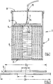
- Figure 1 shows an embodiment of a container or drum for packaging a coil or spool 6 of welding wire 7, such as a flux cored wire or a metal cored wire, according to the present invention.
- the welding wire container comprises a unique hollow body 1, which comprises a peripheral wall 2 and a bottom part 3 at its lower end, said bottom part 3 is integral with the peripheral wall 2.
- the hollow body 1 can further comprise, at its upper end, a cover 8 for closing the container with a central orifice 18, such as a hole or a slot, through which the wire 7 passes during the unwinding of the spool 6 during a welding operation, so that the wire 7 is extracted from the hollow body 1 through the small outlet 18 arranged at the center of the cover 8.
- the hollow body 1, the bottom part 3 and the cover 8 are preferably made of cardboard, such as reinforced cardboard or similar.
- the hollow body 1 has a cylindrical shape. However, it can have other shapes, including polygonal shapes such as square (See Figure 4 ), pentagonal, hexagonal or octagonal (see Figure 5 ).
- the retainers 4, 5 have peripheral profiles or shapes that can match the inner wall of the drum as visible in Figures 3 to 5 .
- the first and second retainers 4, 5 may also have different shapes or profiles, for example one can be circular, whereas the other can be polygonal.
- Peripheral wall 2 is preferably made of one rectangular piece of cardboard that is bent so as to obtain the desired shape forming the hollow body 1 and having its two opposite parallel edges attached one to the other, for instance stapled, glued or bonded together so as to obtain a closed body.
- the bottom part 3 is fixed to said peripheral wall 2 by any suitable connection means, for instance it can be stapled, glued, bonded or similar.
- the internal diameter D of the hollow body 1 is typically between 45 cm and 120 cm, but preferably between 30 and 70 cm, whereas its height is generally between 65 and 130 cm, preferably between 75 and 110 cm.
- a circular coil 6 of welding wire 7 is disposed on the bottom part 3 in said hollow body 1.
- Said wire spool 6 comprises a plurality of wire turns forming spirals.
- a pair of superimposed mobile retainers 4, 5 is arranged on the top of the welding wire coil 6.
- the retainers 4, 5 are place one on the other so as to be in contact one another.
- the first 4 and second 5 retainers are used for maintaining the wire spirals of the coil 6 and for ensuring a smooth extraction of the wire 7 during unwinding, i.e. the wire exits with no or limited twists or knots.
- the axially-mobile retainers 4, 5 both comprise a central opening 14, 15, respectively, through which passes the wire 7, before passing through the central orifice 18 of the cover 8, while being extracted/pulled by the welding machine, such as a welding robot or the like.
- the axially-mobile retainers 4, 5 maintain the wire spirals due to their top-to-bottom motion and weight, and thereby preventing accidental entanglement of the wire spirals forming the spool 6.
- Each retainers 4, 5 consists in a perforated generally flat structure, typically a flat structure, such as a disc made of cardboard, wood or plastic or a combination of these materials. According to the invention, it is important that the first and second retainers 4, 5 have each a flat ring-shape with a central opening 14, 15.
- the first and second retainers 4, 5 can have a same thickness and/or a same weight or have different thicknesses and/or weights, for example a thickness comprises between 0,5 and 20 mm and a weight comprised between 50 g and 5 kg preferably between 60 and 1 kg.
- the dimensions i.e. the diameters D1, D2
- the dimensions of the central opening 14, 15 of the retainer 4, 5 are also carefully chosen to allow a constant and continuous feeding of the wire 7 to a welding torch, at nearly constant drawing force, so that the spooled wire 6 is prevented from entangling and forming loops, as the wire is constantly kept under the axially-mobile retainers 4, 5.
- the first and second retainers 4, 5 have both a smaller size, i.e. diameter D1, D2, than the internal diameter D of the container 1 so that they can freely descend in the container in contact with the coil as the height of said coil decreases as the wire 7 is being unwound from the coil 6.
- the first diameter D 1 of the first retainer 4 is slightly less than the internal diameter D of the container, i.e. the first diameter D1 of the first retainer 4 substantially matches the inner shape and is almost equal to the internal diameter D of the container 1 as defined in claim 1.
- the second retainer 5 has a second diameter D2 that is less than the first diameter D1 of the first retainer 4 and than the internal diameter D of the container 1, i.e. D2 ⁇ D1 ⁇ D.
- the peripheral border of the first retainer 4 is spaced from the inner wall 2 of the drum 1 of a distance E of about 1 to 3 mm, whereas the peripheral border of the second retainer 5 is spaced from the inner wall 2 of the drum 1 of a greater distance E' of about 15 to 30 mm.
- first dimension d1 of the first central opening 14 of the first retainer 4 i.e. its internal diameter as shown in Figure 2
- second dimension d2 of the second central opening 15 of the second retainer 5 i.e. its internal diameter, i.e. d1 > d2. This is important for ensuring a smooth extraction of the wire 7.
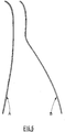
- a container according to the present invention leads to unexpected results in terms of the removal of wire twists or similar effects as shown in Figure 6 .
- wire A extracted from a container according to the present invention exhibits a rather straight-line shape, i.e. almost without any twists or waves
- wire B extracted from a container according to the prior art comprising a unique internal retainer, exhibits a rather wave-shape which is problematic for ensuring a smooth and regular automatic or robotic welding operation using said wire B.
- wire amplitude on the floor (as shown in fig. 6 ) and helix for wires A and B are given in Table 2 below.
- Table 2 Wire A Wire B Wire amplitude on the floor ⁇ 10 cm 20 +/- 35 cm Wire helix ⁇ 0,5 cm 2 +/- 10 cm
- the wire amplitude and helix are both much less for wire A (invention) than for wire B (prior art), leading to a straighter and more linear wire after unwinding. This limits the wire oscillations in the contact tip of the welding torch or similar device, and subsequent welding defects.
- the container of the invention can be arranged on a pallet, for instance a pallet made of wood or of polymer material.
- the container according to the invention is suitable for use in a robotic or automatic welding operation, such as laser or arc welding process, preferably an electric arc welding process, such as a MIG or MAG welding process.
- a robotic or automatic welding operation such as laser or arc welding process, preferably an electric arc welding process, such as a MIG or MAG welding process.
- the wire extracted from the container is fed to a welding torch that is either arranged on a welding machine or on a robotic articulated arm, said torch being used for progressively melting the welding wire and thus obtaining a welding joint.
Landscapes
- Engineering & Computer Science (AREA)
- Mechanical Engineering (AREA)
- Packaging Of Annular Or Rod-Shaped Articles, Wearing Apparel, Cassettes, Or The Like (AREA)
- Unwinding Of Filamentary Materials (AREA)
Claims (13)
- Récipient pour emballer une bobine de fil de soudage, comprenant un corps creux (1) avec une paroi périphérique (2) et une partie inférieure (3), ledit corps creux (1) comprenant en outre un premier élément de maintien (4), ledit premier élément de maintien (4) ayant un premier diamètre (D1) et étant mobile axialement dans ledit corps creux (1), et un second élément de maintien mobile axialement (5) placé sur le premier élément de maintien (4), lesdits premier et second éléments de maintien (4, 5) ayant chacun une forme d'anneau plat avec une ouverture centrale (14, 15), le second élément de maintien (5) ayant un second diamètre (D2) inférieur au premier diamètre (D1), les premier et second éléments de maintien (4, 5) étant agencés sur le dessus d'une bobine de fil de soudage (6) placée à l'intérieur du corps creux (1), une première dimension (d1) de la première ouverture centrale (14) du premier élément de maintien (4) étant supérieure à une seconde dimension (d2) de la seconde ouverture centrale (15) du second élément de maintien (5), le premier élément de maintien et le second élément de maintien pouvant se déplacer l'un par rapport à l'autre lors du déroulage, créant ainsi un espace entre eux,
caractérisé en ce que la limite périphérique du premier élément de maintien (4) est espacée de la paroi périphérique (2) du corps creux (1) d'une première distance (E) d'environ 1 à 3 mm, et la limite périphérique du second élément de maintien (5) est espacée de la paroi périphérique (2) du corps creux (1) d'une seconde distance (E') d'environ 15 à 30 mm. - Récipient selon l'une quelconque des revendications précédentes, caractérisé en ce que la première dimension (d1) de la première ouverture centrale du premier élément de maintien mesure entre 30 et 79 cm, et la seconde dimension (d2) de la seconde ouverture centrale du second élément de maintien mesure entre 29 et 78 cm.
- Récipient selon l'une quelconque des revendications précédentes, caractérisé en ce que les premier et second éléments de maintien (4, 5) sont fabriqués à partir de carton.
- Récipient selon l'une quelconque des revendications précédentes, caractérisé en ce que le premier élément de maintien (4) et le second élément de maintien (5) sont superposés et en contact direct l'un avec l'autre.
- Récipient selon l'une quelconque des revendications précédentes, caractérisé en ce que le premier élément de maintien (4) et le second élément de maintien (5) ont une forme généralement circulaire.
- Récipient selon l'une quelconque des revendications précédentes, caractérisé en ce qu'une bobine circulaire (6) de fil de soudage (7) est disposée sur la partie inférieure (3) dudit corps creux (1).
- Récipient selon l'une quelconque des revendications précédentes, caractérisé en ce que le récipient comprend un couvercle (8).
- Récipient selon l'une quelconque des revendications précédentes, caractérisé en ce que la paroi périphérique (2) du corps creux (1) est fabriquée à partir d'un matériau à base de carton.
- Récipient selon l'une quelconque des revendications précédentes, caractérisé en ce que le diamètre interne (D) du corps creux (1) mesure entre 45 cm et 120 cm et en ce que la hauteur du corps creux (1) mesure entre 65 et 120 cm.
- Récipient selon l'une quelconque des revendications précédentes, caractérisé en ce que le corps creux (1) a une forme cylindrique.
- Récipient selon l'une quelconque des revendications précédentes, caractérisé en ce que les éléments de maintien (4, 5) ont une épaisseur comprise entre 0,5 et 20 mm.
- Récipient selon l'une quelconque des revendications précédentes, caractérisé en ce que les éléments de maintien (4, 5) ont un poids compris entre 50 g et 5 kg.
- Procédé de soudage robotisé ou automatisé, dans lequel un fil de soudage est fondu par un arc électrique ou un faisceau laser, caractérisé en ce que le fil délivré au chalumeau est extrait d'un récipient selon l'une quelconque des revendications précédentes.
Priority Applications (3)
| Application Number | Priority Date | Filing Date | Title |
|---|---|---|---|
| ES12183193.7T ES2648290T3 (es) | 2012-09-05 | 2012-09-05 | Recipiente para alambre de soldadura con dos elementos de retención superpuestos |
| EP12183193.7A EP2706020B1 (fr) | 2012-09-05 | 2012-09-05 | Récipient pour fil de soudage avec deux éléments de maintien superposés |
| PL12183193T PL2706020T3 (pl) | 2012-09-05 | 2012-09-05 | Pojemnik do drutu spawalniczego z nałożonymi dodatkowo dwoma elementami ustalającymi |
Applications Claiming Priority (1)
| Application Number | Priority Date | Filing Date | Title |
|---|---|---|---|
| EP12183193.7A EP2706020B1 (fr) | 2012-09-05 | 2012-09-05 | Récipient pour fil de soudage avec deux éléments de maintien superposés |
Publications (2)
| Publication Number | Publication Date |
|---|---|
| EP2706020A1 EP2706020A1 (fr) | 2014-03-12 |
| EP2706020B1 true EP2706020B1 (fr) | 2017-08-23 |
Family
ID=46934453
Family Applications (1)
| Application Number | Title | Priority Date | Filing Date |
|---|---|---|---|
| EP12183193.7A Not-in-force EP2706020B1 (fr) | 2012-09-05 | 2012-09-05 | Récipient pour fil de soudage avec deux éléments de maintien superposés |
Country Status (3)
| Country | Link |
|---|---|
| EP (1) | EP2706020B1 (fr) |
| ES (1) | ES2648290T3 (fr) |
| PL (1) | PL2706020T3 (fr) |
Family Cites Families (10)
| Publication number | Priority date | Publication date | Assignee | Title |
|---|---|---|---|---|
| JPH0133562Y2 (fr) * | 1984-11-20 | 1989-10-12 | ||
| CA2071419C (fr) | 1991-06-18 | 1996-03-19 | William Dimmett Cooper | Rondelle retenue pour contenant a bobine de fil a souder |
| IT231566Y1 (it) | 1993-02-23 | 1999-08-04 | Sidergas Srl | Contenitore di imballaggio e di svolgimento di una matassa di filo metallico |
| WO1998052844A1 (fr) | 1997-05-20 | 1998-11-26 | Esab Ab | Conteneur pour l'emballage et le deroulement d'une bobine de fil-electrode |
| FR2882038A1 (fr) | 2005-02-17 | 2006-08-18 | Soudure Autogene Francaise Sa | Conteneur de conditionnement de fil de soudage avec dispositif interne de retenue des spires |
| FR2882039B1 (fr) | 2005-02-17 | 2007-04-27 | Soudure Autogene Francaise Sa | Conteneur a paroi interne oblique pour le conditionnement d'un fil de soudage |
| KR100740253B1 (ko) * | 2006-12-13 | 2007-07-16 | 고려용접봉 주식회사 | 용접 와이어용 페일팩 |
| EP2256064A1 (fr) * | 2009-05-27 | 2010-12-01 | ISAF S.p.A. | Conteneur pour fil de soudage avec éléments allongés pour maintenir la bobine de fil |
| EP2354039A1 (fr) * | 2010-01-27 | 2011-08-10 | Oerlikon Schweisstechnik GmbH | Conteneur pour fil de soudage avec système de rétention interne |
| US8985495B2 (en) * | 2010-07-09 | 2015-03-24 | Hyundai Welding Co., Ltd. | Device for preventing entanglement of welding wire |
-
2012
- 2012-09-05 PL PL12183193T patent/PL2706020T3/pl unknown
- 2012-09-05 EP EP12183193.7A patent/EP2706020B1/fr not_active Not-in-force
- 2012-09-05 ES ES12183193.7T patent/ES2648290T3/es active Active
Non-Patent Citations (1)
| Title |
|---|
| None * |
Also Published As
| Publication number | Publication date |
|---|---|
| ES2648290T3 (es) | 2017-12-29 |
| EP2706020A1 (fr) | 2014-03-12 |
| PL2706020T3 (pl) | 2018-01-31 |
Similar Documents
| Publication | Publication Date | Title |
|---|---|---|
| EP2256064A1 (fr) | Conteneur pour fil de soudage avec éléments allongés pour maintenir la bobine de fil | |
| EP2354039A1 (fr) | Conteneur pour fil de soudage avec système de rétention interne | |
| KR100491806B1 (ko) | 대량의 와이어를 수용 및 분배하는 패키지 | |
| KR100638691B1 (ko) | 용접 와이어 페이아웃 드럼 및 그 용접 와이어 저장 스템 | |
| EP2035312B1 (fr) | Bague de guidage pour fil métallique enroulé | |
| JP4347755B2 (ja) | ワイヤパッケージ用リテイナリング | |
| TWI298702B (en) | Welding wire container and method of making the same | |
| US9260269B2 (en) | Wire retaining ring for a welding system | |
| CA2580908C (fr) | Brosse devidoir de fil et contenant comportant une brosse devidoir de fil | |
| CN100384702C (zh) | 具有提带的焊丝包装 | |
| JP2001179450A (ja) | 溶接ワイヤ収納装置 | |
| US12275049B2 (en) | Method for packing welding wire inside containers | |
| EP2612833A1 (fr) | Conteneur pour fil de soudage avec élément à poids glissant par le fil | |
| EP2706020B1 (fr) | Récipient pour fil de soudage avec deux éléments de maintien superposés | |
| EP2353764A1 (fr) | Conteneur pour fil à souder avec un volume mort interne d'une hauteur minimale de 15 cm | |
| EP2151408B1 (fr) | Dispositif pour le conditionnement et le déroulement de câble | |
| EP2634113B1 (fr) | Récipient pour fil de soudage avec structure conique centrale | |
| CN1309630C (zh) | 用于包装焊丝卷和送丝的焊丝容器及固定装置 | |
| JP4809860B2 (ja) | コイル梱包体 | |
| EP2353765A1 (fr) | Conteneur pour fil à souder avec bandes de renfort dans sa paroi périphérique | |
| US20080164366A1 (en) | Method for Winding a Skein Windable Material onto a Spool | |
| KR102185539B1 (ko) | 와이어 수납장치 | |
| JP2902512B2 (ja) | 溶接用容器入りワイヤ | |
| MX2013008698A (es) | Ensamble para transportar bobinas con lamina enrollada y metodo para disponer la lamina sobre un contenedor. | |
| JP2812831B2 (ja) | 溶接用ワイヤ格納容器 |
Legal Events
| Date | Code | Title | Description |
|---|---|---|---|
| PUAI | Public reference made under article 153(3) epc to a published international application that has entered the european phase |
Free format text: ORIGINAL CODE: 0009012 |
|
| AK | Designated contracting states |
Kind code of ref document: A1 Designated state(s): AL AT BE BG CH CY CZ DE DK EE ES FI FR GB GR HR HU IE IS IT LI LT LU LV MC MK MT NL NO PL PT RO RS SE SI SK SM TR |
|
| AX | Request for extension of the european patent |
Extension state: BA ME |
|
| 17P | Request for examination filed |
Effective date: 20140912 |
|
| RBV | Designated contracting states (corrected) |
Designated state(s): AL AT BE BG CH CY CZ DE DK EE ES FI FR GB GR HR HU IE IS IT LI LT LU LV MC MK MT NL NO PL PT RO RS SE SI SK SM TR |
|
| 17Q | First examination report despatched |
Effective date: 20160408 |
|
| STAA | Information on the status of an ep patent application or granted ep patent |
Free format text: STATUS: EXAMINATION IS IN PROGRESS |
|
| GRAP | Despatch of communication of intention to grant a patent |
Free format text: ORIGINAL CODE: EPIDOSNIGR1 |
|
| STAA | Information on the status of an ep patent application or granted ep patent |
Free format text: STATUS: GRANT OF PATENT IS INTENDED |
|
| INTG | Intention to grant announced |
Effective date: 20170601 |
|
| RIN1 | Information on inventor provided before grant (corrected) |
Inventor name: STOCCHETTI, ROBERTO |
|
| GRAS | Grant fee paid |
Free format text: ORIGINAL CODE: EPIDOSNIGR3 |
|
| GRAA | (expected) grant |
Free format text: ORIGINAL CODE: 0009210 |
|
| STAA | Information on the status of an ep patent application or granted ep patent |
Free format text: STATUS: THE PATENT HAS BEEN GRANTED |
|
| AK | Designated contracting states |
Kind code of ref document: B1 Designated state(s): AL AT BE BG CH CY CZ DE DK EE ES FI FR GB GR HR HU IE IS IT LI LT LU LV MC MK MT NL NO PL PT RO RS SE SI SK SM TR |
|
| REG | Reference to a national code |
Ref country code: GB Ref legal event code: FG4D |
|
| REG | Reference to a national code |
Ref country code: CH Ref legal event code: EP |
|
| REG | Reference to a national code |
Ref country code: AT Ref legal event code: REF Ref document number: 921075 Country of ref document: AT Kind code of ref document: T Effective date: 20170915 |
|
| REG | Reference to a national code |
Ref country code: IE Ref legal event code: FG4D |
|
| REG | Reference to a national code |
Ref country code: FR Ref legal event code: PLFP Year of fee payment: 6 |
|
| REG | Reference to a national code |
Ref country code: DE Ref legal event code: R096 Ref document number: 602012036203 Country of ref document: DE |
|
| REG | Reference to a national code |
Ref country code: SE Ref legal event code: TRGR |
|
| REG | Reference to a national code |
Ref country code: NL Ref legal event code: MP Effective date: 20170823 |
|
| REG | Reference to a national code |
Ref country code: ES Ref legal event code: FG2A Ref document number: 2648290 Country of ref document: ES Kind code of ref document: T3 Effective date: 20171229 |
|
| REG | Reference to a national code |
Ref country code: LT Ref legal event code: MG4D |
|
| PG25 | Lapsed in a contracting state [announced via postgrant information from national office to epo] |
Ref country code: LT Free format text: LAPSE BECAUSE OF FAILURE TO SUBMIT A TRANSLATION OF THE DESCRIPTION OR TO PAY THE FEE WITHIN THE PRESCRIBED TIME-LIMIT Effective date: 20170823 Ref country code: FI Free format text: LAPSE BECAUSE OF FAILURE TO SUBMIT A TRANSLATION OF THE DESCRIPTION OR TO PAY THE FEE WITHIN THE PRESCRIBED TIME-LIMIT Effective date: 20170823 Ref country code: NO Free format text: LAPSE BECAUSE OF FAILURE TO SUBMIT A TRANSLATION OF THE DESCRIPTION OR TO PAY THE FEE WITHIN THE PRESCRIBED TIME-LIMIT Effective date: 20171123 Ref country code: HR Free format text: LAPSE BECAUSE OF FAILURE TO SUBMIT A TRANSLATION OF THE DESCRIPTION OR TO PAY THE FEE WITHIN THE PRESCRIBED TIME-LIMIT Effective date: 20170823 Ref country code: NL Free format text: LAPSE BECAUSE OF FAILURE TO SUBMIT A TRANSLATION OF THE DESCRIPTION OR TO PAY THE FEE WITHIN THE PRESCRIBED TIME-LIMIT Effective date: 20170823 |
|
| PG25 | Lapsed in a contracting state [announced via postgrant information from national office to epo] |
Ref country code: GR Free format text: LAPSE BECAUSE OF FAILURE TO SUBMIT A TRANSLATION OF THE DESCRIPTION OR TO PAY THE FEE WITHIN THE PRESCRIBED TIME-LIMIT Effective date: 20171124 Ref country code: BG Free format text: LAPSE BECAUSE OF FAILURE TO SUBMIT A TRANSLATION OF THE DESCRIPTION OR TO PAY THE FEE WITHIN THE PRESCRIBED TIME-LIMIT Effective date: 20171123 Ref country code: RS Free format text: LAPSE BECAUSE OF FAILURE TO SUBMIT A TRANSLATION OF THE DESCRIPTION OR TO PAY THE FEE WITHIN THE PRESCRIBED TIME-LIMIT Effective date: 20170823 Ref country code: IS Free format text: LAPSE BECAUSE OF FAILURE TO SUBMIT A TRANSLATION OF THE DESCRIPTION OR TO PAY THE FEE WITHIN THE PRESCRIBED TIME-LIMIT Effective date: 20171223 Ref country code: LV Free format text: LAPSE BECAUSE OF FAILURE TO SUBMIT A TRANSLATION OF THE DESCRIPTION OR TO PAY THE FEE WITHIN THE PRESCRIBED TIME-LIMIT Effective date: 20170823 |
|
| PG25 | Lapsed in a contracting state [announced via postgrant information from national office to epo] |
Ref country code: RO Free format text: LAPSE BECAUSE OF FAILURE TO SUBMIT A TRANSLATION OF THE DESCRIPTION OR TO PAY THE FEE WITHIN THE PRESCRIBED TIME-LIMIT Effective date: 20170823 Ref country code: DK Free format text: LAPSE BECAUSE OF FAILURE TO SUBMIT A TRANSLATION OF THE DESCRIPTION OR TO PAY THE FEE WITHIN THE PRESCRIBED TIME-LIMIT Effective date: 20170823 |
|
| REG | Reference to a national code |
Ref country code: CH Ref legal event code: PL |
|
| REG | Reference to a national code |
Ref country code: DE Ref legal event code: R097 Ref document number: 602012036203 Country of ref document: DE |
|
| PG25 | Lapsed in a contracting state [announced via postgrant information from national office to epo] |
Ref country code: SK Free format text: LAPSE BECAUSE OF FAILURE TO SUBMIT A TRANSLATION OF THE DESCRIPTION OR TO PAY THE FEE WITHIN THE PRESCRIBED TIME-LIMIT Effective date: 20170823 Ref country code: EE Free format text: LAPSE BECAUSE OF FAILURE TO SUBMIT A TRANSLATION OF THE DESCRIPTION OR TO PAY THE FEE WITHIN THE PRESCRIBED TIME-LIMIT Effective date: 20170823 Ref country code: SM Free format text: LAPSE BECAUSE OF FAILURE TO SUBMIT A TRANSLATION OF THE DESCRIPTION OR TO PAY THE FEE WITHIN THE PRESCRIBED TIME-LIMIT Effective date: 20170823 Ref country code: MC Free format text: LAPSE BECAUSE OF FAILURE TO SUBMIT A TRANSLATION OF THE DESCRIPTION OR TO PAY THE FEE WITHIN THE PRESCRIBED TIME-LIMIT Effective date: 20170823 |
|
| REG | Reference to a national code |
Ref country code: IE Ref legal event code: MM4A |
|
| REG | Reference to a national code |
Ref country code: BE Ref legal event code: MM Effective date: 20170930 |
|
| PG25 | Lapsed in a contracting state [announced via postgrant information from national office to epo] |
Ref country code: LU Free format text: LAPSE BECAUSE OF NON-PAYMENT OF DUE FEES Effective date: 20170905 |
|
| PLBE | No opposition filed within time limit |
Free format text: ORIGINAL CODE: 0009261 |
|
| STAA | Information on the status of an ep patent application or granted ep patent |
Free format text: STATUS: NO OPPOSITION FILED WITHIN TIME LIMIT |
|
| GBPC | Gb: european patent ceased through non-payment of renewal fee |
Effective date: 20171123 |
|
| PG25 | Lapsed in a contracting state [announced via postgrant information from national office to epo] |
Ref country code: CH Free format text: LAPSE BECAUSE OF NON-PAYMENT OF DUE FEES Effective date: 20170930 Ref country code: LI Free format text: LAPSE BECAUSE OF NON-PAYMENT OF DUE FEES Effective date: 20170930 Ref country code: IE Free format text: LAPSE BECAUSE OF NON-PAYMENT OF DUE FEES Effective date: 20170905 |
|
| 26N | No opposition filed |
Effective date: 20180524 |
|
| PG25 | Lapsed in a contracting state [announced via postgrant information from national office to epo] |
Ref country code: BE Free format text: LAPSE BECAUSE OF NON-PAYMENT OF DUE FEES Effective date: 20170930 Ref country code: SI Free format text: LAPSE BECAUSE OF FAILURE TO SUBMIT A TRANSLATION OF THE DESCRIPTION OR TO PAY THE FEE WITHIN THE PRESCRIBED TIME-LIMIT Effective date: 20170823 |
|
| REG | Reference to a national code |
Ref country code: FR Ref legal event code: PLFP Year of fee payment: 7 |
|
| PG25 | Lapsed in a contracting state [announced via postgrant information from national office to epo] |
Ref country code: MT Free format text: LAPSE BECAUSE OF NON-PAYMENT OF DUE FEES Effective date: 20170905 |
|
| PG25 | Lapsed in a contracting state [announced via postgrant information from national office to epo] |
Ref country code: GB Free format text: LAPSE BECAUSE OF NON-PAYMENT OF DUE FEES Effective date: 20171123 |
|
| PG25 | Lapsed in a contracting state [announced via postgrant information from national office to epo] |
Ref country code: HU Free format text: LAPSE BECAUSE OF FAILURE TO SUBMIT A TRANSLATION OF THE DESCRIPTION OR TO PAY THE FEE WITHIN THE PRESCRIBED TIME-LIMIT; INVALID AB INITIO Effective date: 20120905 |
|
| PG25 | Lapsed in a contracting state [announced via postgrant information from national office to epo] |
Ref country code: CY Free format text: LAPSE BECAUSE OF NON-PAYMENT OF DUE FEES Effective date: 20170823 |
|
| PG25 | Lapsed in a contracting state [announced via postgrant information from national office to epo] |
Ref country code: MK Free format text: LAPSE BECAUSE OF FAILURE TO SUBMIT A TRANSLATION OF THE DESCRIPTION OR TO PAY THE FEE WITHIN THE PRESCRIBED TIME-LIMIT Effective date: 20170823 |
|
| PG25 | Lapsed in a contracting state [announced via postgrant information from national office to epo] |
Ref country code: TR Free format text: LAPSE BECAUSE OF FAILURE TO SUBMIT A TRANSLATION OF THE DESCRIPTION OR TO PAY THE FEE WITHIN THE PRESCRIBED TIME-LIMIT Effective date: 20170823 |
|
| PG25 | Lapsed in a contracting state [announced via postgrant information from national office to epo] |
Ref country code: PT Free format text: LAPSE BECAUSE OF FAILURE TO SUBMIT A TRANSLATION OF THE DESCRIPTION OR TO PAY THE FEE WITHIN THE PRESCRIBED TIME-LIMIT Effective date: 20170823 |
|
| PG25 | Lapsed in a contracting state [announced via postgrant information from national office to epo] |
Ref country code: AL Free format text: LAPSE BECAUSE OF FAILURE TO SUBMIT A TRANSLATION OF THE DESCRIPTION OR TO PAY THE FEE WITHIN THE PRESCRIBED TIME-LIMIT Effective date: 20170823 |
|
| REG | Reference to a national code |
Ref country code: AT Ref legal event code: UEP Ref document number: 921075 Country of ref document: AT Kind code of ref document: T Effective date: 20170823 |
|
| PGFP | Annual fee paid to national office [announced via postgrant information from national office to epo] |
Ref country code: AT Payment date: 20210917 Year of fee payment: 10 Ref country code: CZ Payment date: 20210825 Year of fee payment: 10 Ref country code: IT Payment date: 20210930 Year of fee payment: 10 Ref country code: FR Payment date: 20210929 Year of fee payment: 10 |
|
| PGFP | Annual fee paid to national office [announced via postgrant information from national office to epo] |
Ref country code: SE Payment date: 20210921 Year of fee payment: 10 Ref country code: PL Payment date: 20210826 Year of fee payment: 10 Ref country code: DE Payment date: 20210921 Year of fee payment: 10 |
|
| PGFP | Annual fee paid to national office [announced via postgrant information from national office to epo] |
Ref country code: ES Payment date: 20211019 Year of fee payment: 10 |
|
| REG | Reference to a national code |
Ref country code: DE Ref legal event code: R119 Ref document number: 602012036203 Country of ref document: DE |
|
| PG25 | Lapsed in a contracting state [announced via postgrant information from national office to epo] |
Ref country code: CZ Free format text: LAPSE BECAUSE OF NON-PAYMENT OF DUE FEES Effective date: 20220905 |
|
| REG | Reference to a national code |
Ref country code: SE Ref legal event code: EUG |
|
| REG | Reference to a national code |
Ref country code: AT Ref legal event code: MM01 Ref document number: 921075 Country of ref document: AT Kind code of ref document: T Effective date: 20220905 |
|
| PG25 | Lapsed in a contracting state [announced via postgrant information from national office to epo] |
Ref country code: FR Free format text: LAPSE BECAUSE OF NON-PAYMENT OF DUE FEES Effective date: 20220930 Ref country code: DE Free format text: LAPSE BECAUSE OF NON-PAYMENT OF DUE FEES Effective date: 20230401 Ref country code: AT Free format text: LAPSE BECAUSE OF NON-PAYMENT OF DUE FEES Effective date: 20220905 |
|
| PG25 | Lapsed in a contracting state [announced via postgrant information from national office to epo] |
Ref country code: SE Free format text: LAPSE BECAUSE OF NON-PAYMENT OF DUE FEES Effective date: 20220906 |
|
| REG | Reference to a national code |
Ref country code: ES Ref legal event code: FD2A Effective date: 20231026 |
|
| PG25 | Lapsed in a contracting state [announced via postgrant information from national office to epo] |
Ref country code: IT Free format text: LAPSE BECAUSE OF NON-PAYMENT OF DUE FEES Effective date: 20220905 |
|
| PG25 | Lapsed in a contracting state [announced via postgrant information from national office to epo] |
Ref country code: PL Free format text: LAPSE BECAUSE OF NON-PAYMENT OF DUE FEES Effective date: 20220905 |
|
| PG25 | Lapsed in a contracting state [announced via postgrant information from national office to epo] |
Ref country code: ES Free format text: LAPSE BECAUSE OF NON-PAYMENT OF DUE FEES Effective date: 20220906 |
|
| PG25 | Lapsed in a contracting state [announced via postgrant information from national office to epo] |
Ref country code: ES Free format text: LAPSE BECAUSE OF NON-PAYMENT OF DUE FEES Effective date: 20220906 |