EP2706495A1 - Récepteur de référence pour signal d'activation pour des systèmes de billetterie électronique - Google Patents
Récepteur de référence pour signal d'activation pour des systèmes de billetterie électronique Download PDFInfo
- Publication number
- EP2706495A1 EP2706495A1 EP12183126.7A EP12183126A EP2706495A1 EP 2706495 A1 EP2706495 A1 EP 2706495A1 EP 12183126 A EP12183126 A EP 12183126A EP 2706495 A1 EP2706495 A1 EP 2706495A1
- Authority
- EP
- European Patent Office
- Prior art keywords
- wake
- signal
- transport
- unit
- tickets
- Prior art date
- Legal status (The legal status is an assumption and is not a legal conclusion. Google has not performed a legal analysis and makes no representation as to the accuracy of the status listed.)
- Withdrawn
Links
Images


Classifications
-
- G—PHYSICS
- G06—COMPUTING OR CALCULATING; COUNTING
- G06Q—INFORMATION AND COMMUNICATION TECHNOLOGY [ICT] SPECIALLY ADAPTED FOR ADMINISTRATIVE, COMMERCIAL, FINANCIAL, MANAGERIAL OR SUPERVISORY PURPOSES; SYSTEMS OR METHODS SPECIALLY ADAPTED FOR ADMINISTRATIVE, COMMERCIAL, FINANCIAL, MANAGERIAL OR SUPERVISORY PURPOSES, NOT OTHERWISE PROVIDED FOR
- G06Q20/00—Payment architectures, schemes or protocols
- G06Q20/04—Payment circuits
- G06Q20/045—Payment circuits using payment protocols involving tickets
-
- G—PHYSICS
- G07—CHECKING-DEVICES
- G07B—TICKET-ISSUING APPARATUS; FARE-REGISTERING APPARATUS; FRANKING APPARATUS
- G07B15/00—Arrangements or apparatus for collecting fares, tolls or entrance fees at one or more control points
Definitions
- the present invention relates to a method and a system for monitoring the wake-up process of an e-ticket according to claim 1 or claim 9.
- the ticket is automatically recorded by the radio within the traveled sections of the track by the reading units installed in the car and the data thus obtained Data fed to an automatic billing system.
- An interaction of the user is no longer necessary. It also does not need a check-out process.
- the flow of passengers can be accelerated considerably, especially when passengers are getting in / out at the same time.
- the e-ticket is "woken up” when passing through the entrance area in a car via RF signals from antennas installed there.
- the term “stamped” is more than just “awakening” subsumed.
- the problem described above appears to be particularly explosive in the more comfortable collection / billing system described above, because with the aid of the described manipulation method, undetected journeys can be carried out without appropriate billing (even during checks). The hidden entrainment of a jammer and its operation can not be prevented.
- the present invention is therefore based on the object of specifying a system and a method for registering e-tickets, which system and a method monitors the waking up of the e-tickets and detects and signals manipulations by means of jammers.
- FIG. 1 shows a railway carriage 30 with windows 35 and an entrance area 31 as an example of a means of transport 30.
- two e-tickets 10 are shown, in reality there are at a certain time a larger number of e-tickets in the entrance area 31, each one a carrier or passengers such as people, dogs or luggage. While driving, this entrance area 31 is outwards with a door 37 - here in the example according to the FIG. 1 a sliding door 37 - closed.
- the awakening of the e-tickets 10 is done in this example with a side mounted in the entrance area 31 antennas 26, which are formed for example as a coil system 26.
- the electronics 25 for the wake-up transmitter is hereby installed under a cover over an entrance region 31 of the railway carriage 30.
- the antennas 26 associated with the wake-up system 26 are housed in flat housings, facing left and right on the sidewalls of the entrance area 31. Awake transmitter and associated antennas are known in the art.
- reference receiver 28 Below the antennas 26, preferably also incorporated in the flat housing, reference receiver 28 are still arranged.
- the reference receivers 28 evaluate the respective signal radiated from the opposite antenna and provide feedback to the electronics 26 or to another unit controlling the detection of the e-tickets in the railway car, whether a valid wake-up operation has taken place.
- this unit is a transmitting / receiving unit 20.
- the reference receiver 28 may be located in the same housing as the transmitting antennas 26. This makes it possible to connect the reference receiver 28 via signal lines or optionally to carry out the transmission of the messages by radio.
- FIG. 2 shows a possible arrangement and structural design of the described components antenna 26 and reference receiver 28 in a flat housing 22, which can be mounted in a simple way laterally in the entrance area.
- a tab 29 and holes 27 are provided for mounting screws.
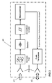
- wake-up signal 41 (here: AM modulation) is passed through a band-pass filter to suppress unwanted interference from adjacent frequency bands, then rectified (demodulation) and guided to a threshold. Its output signal (logic level) is fed to a microcontroller, which compares the incoming bit stream with a predetermined bit pattern. In the case of a match, a logical signal "wake-up sequence received" is set to "1" and the illustrated radio transceiver transmits a corresponding message 40 via the lower antenna by radio.
- the message is received and further processed, for example, by a transmitter / receiver unit 20 mounted on the inside of the car ceiling. Instead of a radio transmission, the message can also be transmitted via a physical line of the transmitting / receiving unit 20 be supplied.
- This principle can be implemented in various forms:
- the messages 40 advantageously have a structure with the contents in Table 1 below.
- the differentiation with the three cases depends on the operational use and collision management.
- the data in Table 1 are alternative or cumulative.
- the reference receivers 28 are provided as part of the interior, the Id vehicle is not transmitted unless, in particular, these reference receivers 28 are still configured during installation.
- a corresponding message 40 is sent to the higher-level system, e.g. Transmitting / receiving unit 20 delivered.
- the aforesaid feedback may continue in the receiving system, e.g. the transmitting / receiving unit 20 are evaluated so that for another message to the outside at least two messages 40 must match, this as a so-called plausibility check.
- a warning message in the cab for the locomotive driver can be issued. It is also conceivable a message to the railway police or transport police with indication of the train (course) and the car; Transport police, railway police or driver's cab are collectively referred to as supervisory authority.
- the reference receivers 28 are (similar to in FIG. 3 shown block diagram) designed as independent, battery-powered units. These are arranged at several different locations in the entrance area 31 of a means of transport 30. This is special advantageous if the entrance area 31 is relatively large and a large stream of carriers such as humans and dogs of all sizes of e-tickets 10 is to be detected so that as possible all e-tickets 10 are awakened and faults are reliably detected.
- the messages 40 are preferably transmitted by radio to the transceiver unit (s) 20 installed below or on the trolley ceiling.
- the aforementioned reference receivers 28 as independent, battery-powered units are incorporated in advance in the parts of the interior of a car. This allows a covert and cost-effective integration. The reference receivers 28 could then be renewed along with interior parts at regular intervals.
- This solution also allows a functional check of the involved components.
- the results of this functional check can be recorded in a log file (vehicle-specific).
- the reference receivers 28 may be supplied with electrical power via a connection to the antenna units 26, the waking transmitter 25 or other means in the means of transport 30. Alternatively, the reference receiver 28 can be powered by built-in batteries or batteries with electrical energy.
Landscapes
- Business, Economics & Management (AREA)
- Physics & Mathematics (AREA)
- General Physics & Mathematics (AREA)
- Accounting & Taxation (AREA)
- Strategic Management (AREA)
- General Business, Economics & Management (AREA)
- Engineering & Computer Science (AREA)
- Theoretical Computer Science (AREA)
- Finance (AREA)
- Devices For Checking Fares Or Tickets At Control Points (AREA)
Priority Applications (1)
| Application Number | Priority Date | Filing Date | Title |
|---|---|---|---|
| EP12183126.7A EP2706495A1 (fr) | 2012-09-05 | 2012-09-05 | Récepteur de référence pour signal d'activation pour des systèmes de billetterie électronique |
Applications Claiming Priority (1)
| Application Number | Priority Date | Filing Date | Title |
|---|---|---|---|
| EP12183126.7A EP2706495A1 (fr) | 2012-09-05 | 2012-09-05 | Récepteur de référence pour signal d'activation pour des systèmes de billetterie électronique |
Publications (1)
| Publication Number | Publication Date |
|---|---|
| EP2706495A1 true EP2706495A1 (fr) | 2014-03-12 |
Family
ID=47172258
Family Applications (1)
| Application Number | Title | Priority Date | Filing Date |
|---|---|---|---|
| EP12183126.7A Withdrawn EP2706495A1 (fr) | 2012-09-05 | 2012-09-05 | Récepteur de référence pour signal d'activation pour des systèmes de billetterie électronique |
Country Status (1)
| Country | Link |
|---|---|
| EP (1) | EP2706495A1 (fr) |
Citations (4)
| Publication number | Priority date | Publication date | Assignee | Title |
|---|---|---|---|---|
| EP1210693A1 (fr) * | 1999-09-10 | 2002-06-05 | Häni Prolectron Ag | Procede et systeme d'enregistrement de billets |
| WO2002056237A2 (fr) * | 2001-01-09 | 2002-07-18 | Siemens Transit Systems Ag | Procede de facturation d'une prestation correspondante |
| EP1201693B1 (fr) | 2000-10-24 | 2005-07-27 | Toyo Engineering Corporation | Composition de polystyrène modifié par un caoutchouc et résistant à l' huile |
| EP1667074A1 (fr) * | 2004-12-02 | 2006-06-07 | mcity GmbH | Méthode automatique de détecter l'utilisation des vehicules payants et de facturer le prix du voyage |
-
2012
- 2012-09-05 EP EP12183126.7A patent/EP2706495A1/fr not_active Withdrawn
Patent Citations (4)
| Publication number | Priority date | Publication date | Assignee | Title |
|---|---|---|---|---|
| EP1210693A1 (fr) * | 1999-09-10 | 2002-06-05 | Häni Prolectron Ag | Procede et systeme d'enregistrement de billets |
| EP1201693B1 (fr) | 2000-10-24 | 2005-07-27 | Toyo Engineering Corporation | Composition de polystyrène modifié par un caoutchouc et résistant à l' huile |
| WO2002056237A2 (fr) * | 2001-01-09 | 2002-07-18 | Siemens Transit Systems Ag | Procede de facturation d'une prestation correspondante |
| EP1667074A1 (fr) * | 2004-12-02 | 2006-06-07 | mcity GmbH | Méthode automatique de détecter l'utilisation des vehicules payants et de facturer le prix du voyage |
Similar Documents
| Publication | Publication Date | Title |
|---|---|---|
| DE102019212231B4 (de) | Verfahren zur Tür- oder Klappenbedienung bei einem Fahrzeug sowie Authentifizierungselement | |
| EP2334535B1 (fr) | Procédé et dispositif pour accroître la précision d'arrêt d'un objet déplacé | |
| EP3198246B1 (fr) | Procédé de détermination d'un état dans un véhicule ferroviaire | |
| DE69532935T2 (de) | Integriertes Fahrzeugkommunikationssystem | |
| EP1210693B1 (fr) | Procede et systeme d'enregistrement de billets | |
| EP1669935A1 (fr) | Méthode automatique de détecter l'utilisation des vehicules payants et de facturer le prix du voyage | |
| EP0919971B1 (fr) | Système et procédé antivol pour détecter et identifier automatiquement une étiquette de surveillance d'articles | |
| EP3261060B1 (fr) | Procédés de contrôle d'accès dans un système de contrôle d'accès pour personnes ou véhicules automobiles et système de contrôle d'accès | |
| CH706520A2 (de) | Verfahren und Vorrichtung zur Erfassung und Abrechnung von Leistungsentgelten in öffentlichen Verkehrsmitteln. | |
| EP4079594B1 (fr) | Dispositif de surveillance pour un système ferroviaire et procédé | |
| EP2756327A1 (fr) | Dispositif et procédé permettant de déterminer des informations d'itinéraire | |
| DE60002856T2 (de) | Verfahren zur verwaltung von elektronischen fahrkarten und einrichtung zu dessen durchführung | |
| EP1362330B1 (fr) | Procede d'enregistrement de billets | |
| DE102016217331A1 (de) | Verfahren und Vorrichtung zum Ermitteln einer Anwesenheit wenigstens eines Fahrgasts in einem Fahrzeug | |
| EP2439712A1 (fr) | Procédé et dispositif de détection de véhicules automobiles dans un réseau de circulation | |
| EP2100763B1 (fr) | Procédé et dispositif de contrôle d'un dispositif motorisé and dispositif mobile | |
| EP2733676B1 (fr) | Procédé et système contre les manipulations pour les systèmes de billetterie électronique | |
| DE10246668A1 (de) | Zutrittskontrollsystem und Verfahren zum Betrieb eines solchen Zutrittskontrollsystemes | |
| DE102016213395A1 (de) | Verfahren und System zur Anwesenheitserfassung und/oder Fahrpreisermittlung für einen Fahrgast in einem Fahrzeug | |
| EP3252697B1 (fr) | Dispositif de validation pour un systeme de ticket | |
| DE102006053618A1 (de) | Anordnung zum Überwachen eines Fahrzeugs | |
| EP2696329A1 (fr) | Procédé et système de localisation d'un billet électronique dans un moyen de transport | |
| EP2871614A1 (fr) | Procédé d'enregistrement de tickets électroniques en excluant des tickets électroniques voyageant en parallèle | |
| EP2677457B1 (fr) | Procédé et système de localisation d'un billet électronique dans un moyen de transport | |
| DE102019215538B4 (de) | Abstandsmesssystem |
Legal Events
| Date | Code | Title | Description |
|---|---|---|---|
| PUAI | Public reference made under article 153(3) epc to a published international application that has entered the european phase |
Free format text: ORIGINAL CODE: 0009012 |
|
| AK | Designated contracting states |
Kind code of ref document: A1 Designated state(s): AL AT BE BG CH CY CZ DE DK EE ES FI FR GB GR HR HU IE IS IT LI LT LU LV MC MK MT NL NO PL PT RO RS SE SI SK SM TR |
|
| AX | Request for extension of the european patent |
Extension state: BA ME |
|
| STAA | Information on the status of an ep patent application or granted ep patent |
Free format text: STATUS: THE APPLICATION IS DEEMED TO BE WITHDRAWN |
|
| 18D | Application deemed to be withdrawn |
Effective date: 20140913 |