EP2707652B1 - Hochenergetische led-beleuchtungseinheit - Google Patents
Hochenergetische led-beleuchtungseinheit Download PDFInfo
- Publication number
- EP2707652B1 EP2707652B1 EP12786058.3A EP12786058A EP2707652B1 EP 2707652 B1 EP2707652 B1 EP 2707652B1 EP 12786058 A EP12786058 A EP 12786058A EP 2707652 B1 EP2707652 B1 EP 2707652B1
- Authority
- EP
- European Patent Office
- Prior art keywords
- housing
- solid
- power supply
- lighting unit
- state
- Prior art date
- Legal status (The legal status is an assumption and is not a legal conclusion. Google has not performed a legal analysis and makes no representation as to the accuracy of the status listed.)
- Active
Links
Images


Classifications
-
- F—MECHANICAL ENGINEERING; LIGHTING; HEATING; WEAPONS; BLASTING
- F21—LIGHTING
- F21V—FUNCTIONAL FEATURES OR DETAILS OF LIGHTING DEVICES OR SYSTEMS THEREOF; STRUCTURAL COMBINATIONS OF LIGHTING DEVICES WITH OTHER ARTICLES, NOT OTHERWISE PROVIDED FOR
- F21V29/00—Protecting lighting devices from thermal damage; Cooling or heating arrangements specially adapted for lighting devices or systems
- F21V29/50—Cooling arrangements
- F21V29/502—Cooling arrangements characterised by the adaptation for cooling of specific components
- F21V29/507—Cooling arrangements characterised by the adaptation for cooling of specific components of means for protecting lighting devices from damage, e.g. housings
-
- F—MECHANICAL ENGINEERING; LIGHTING; HEATING; WEAPONS; BLASTING
- F21—LIGHTING
- F21V—FUNCTIONAL FEATURES OR DETAILS OF LIGHTING DEVICES OR SYSTEMS THEREOF; STRUCTURAL COMBINATIONS OF LIGHTING DEVICES WITH OTHER ARTICLES, NOT OTHERWISE PROVIDED FOR
- F21V5/00—Refractors for light sources
- F21V5/007—Array of lenses or refractors for a cluster of light sources, e.g. for arrangement of multiple light sources in one plane
-
- F—MECHANICAL ENGINEERING; LIGHTING; HEATING; WEAPONS; BLASTING
- F21—LIGHTING
- F21V—FUNCTIONAL FEATURES OR DETAILS OF LIGHTING DEVICES OR SYSTEMS THEREOF; STRUCTURAL COMBINATIONS OF LIGHTING DEVICES WITH OTHER ARTICLES, NOT OTHERWISE PROVIDED FOR
- F21V29/00—Protecting lighting devices from thermal damage; Cooling or heating arrangements specially adapted for lighting devices or systems
- F21V29/50—Cooling arrangements
- F21V29/70—Cooling arrangements characterised by passive heat-dissipating elements, e.g. heat-sinks
- F21V29/74—Cooling arrangements characterised by passive heat-dissipating elements, e.g. heat-sinks with fins or blades
-
- F—MECHANICAL ENGINEERING; LIGHTING; HEATING; WEAPONS; BLASTING
- F21—LIGHTING
- F21V—FUNCTIONAL FEATURES OR DETAILS OF LIGHTING DEVICES OR SYSTEMS THEREOF; STRUCTURAL COMBINATIONS OF LIGHTING DEVICES WITH OTHER ARTICLES, NOT OTHERWISE PROVIDED FOR
- F21V29/00—Protecting lighting devices from thermal damage; Cooling or heating arrangements specially adapted for lighting devices or systems
- F21V29/50—Cooling arrangements
- F21V29/70—Cooling arrangements characterised by passive heat-dissipating elements, e.g. heat-sinks
- F21V29/80—Cooling arrangements characterised by passive heat-dissipating elements, e.g. heat-sinks with pins or wires
-
- F—MECHANICAL ENGINEERING; LIGHTING; HEATING; WEAPONS; BLASTING
- F21—LIGHTING
- F21V—FUNCTIONAL FEATURES OR DETAILS OF LIGHTING DEVICES OR SYSTEMS THEREOF; STRUCTURAL COMBINATIONS OF LIGHTING DEVICES WITH OTHER ARTICLES, NOT OTHERWISE PROVIDED FOR
- F21V29/00—Protecting lighting devices from thermal damage; Cooling or heating arrangements specially adapted for lighting devices or systems
- F21V29/50—Cooling arrangements
- F21V29/70—Cooling arrangements characterised by passive heat-dissipating elements, e.g. heat-sinks
- F21V29/83—Cooling arrangements characterised by passive heat-dissipating elements, e.g. heat-sinks the elements having apertures, ducts or channels, e.g. heat radiation holes
-
- F—MECHANICAL ENGINEERING; LIGHTING; HEATING; WEAPONS; BLASTING
- F21—LIGHTING
- F21V—FUNCTIONAL FEATURES OR DETAILS OF LIGHTING DEVICES OR SYSTEMS THEREOF; STRUCTURAL COMBINATIONS OF LIGHTING DEVICES WITH OTHER ARTICLES, NOT OTHERWISE PROVIDED FOR
- F21V21/00—Supporting, suspending, or attaching arrangements for lighting devices; Hand grips
- F21V21/14—Adjustable mountings
- F21V21/30—Pivoted housings or frames
-
- F—MECHANICAL ENGINEERING; LIGHTING; HEATING; WEAPONS; BLASTING
- F21—LIGHTING
- F21V—FUNCTIONAL FEATURES OR DETAILS OF LIGHTING DEVICES OR SYSTEMS THEREOF; STRUCTURAL COMBINATIONS OF LIGHTING DEVICES WITH OTHER ARTICLES, NOT OTHERWISE PROVIDED FOR
- F21V23/00—Arrangement of electric circuit elements in or on lighting devices
- F21V23/02—Arrangement of electric circuit elements in or on lighting devices the elements being transformers, impedances or power supply units, e.g. a transformer with a rectifier
- F21V23/023—Power supplies in a casing
-
- F—MECHANICAL ENGINEERING; LIGHTING; HEATING; WEAPONS; BLASTING
- F21—LIGHTING
- F21V—FUNCTIONAL FEATURES OR DETAILS OF LIGHTING DEVICES OR SYSTEMS THEREOF; STRUCTURAL COMBINATIONS OF LIGHTING DEVICES WITH OTHER ARTICLES, NOT OTHERWISE PROVIDED FOR
- F21V29/00—Protecting lighting devices from thermal damage; Cooling or heating arrangements specially adapted for lighting devices or systems
- F21V29/15—Thermal insulation
-
- F—MECHANICAL ENGINEERING; LIGHTING; HEATING; WEAPONS; BLASTING
- F21—LIGHTING
- F21V—FUNCTIONAL FEATURES OR DETAILS OF LIGHTING DEVICES OR SYSTEMS THEREOF; STRUCTURAL COMBINATIONS OF LIGHTING DEVICES WITH OTHER ARTICLES, NOT OTHERWISE PROVIDED FOR
- F21V29/00—Protecting lighting devices from thermal damage; Cooling or heating arrangements specially adapted for lighting devices or systems
- F21V29/85—Protecting lighting devices from thermal damage; Cooling or heating arrangements specially adapted for lighting devices or systems characterised by the material
- F21V29/89—Metals
-
- F—MECHANICAL ENGINEERING; LIGHTING; HEATING; WEAPONS; BLASTING
- F21—LIGHTING
- F21Y—INDEXING SCHEME ASSOCIATED WITH SUBCLASSES F21K, F21L, F21S and F21V, RELATING TO THE FORM OR THE KIND OF THE LIGHT SOURCES OR OF THE COLOUR OF THE LIGHT EMITTED
- F21Y2105/00—Planar light sources
- F21Y2105/10—Planar light sources comprising a two-dimensional [2D] array of point-like light-generating elements
-
- F—MECHANICAL ENGINEERING; LIGHTING; HEATING; WEAPONS; BLASTING
- F21—LIGHTING
- F21Y—INDEXING SCHEME ASSOCIATED WITH SUBCLASSES F21K, F21L, F21S and F21V, RELATING TO THE FORM OR THE KIND OF THE LIGHT SOURCES OR OF THE COLOUR OF THE LIGHT EMITTED
- F21Y2115/00—Light-generating elements of semiconductor light sources
- F21Y2115/10—Light-emitting diodes [LED]
-
- Y—GENERAL TAGGING OF NEW TECHNOLOGICAL DEVELOPMENTS; GENERAL TAGGING OF CROSS-SECTIONAL TECHNOLOGIES SPANNING OVER SEVERAL SECTIONS OF THE IPC; TECHNICAL SUBJECTS COVERED BY FORMER USPC CROSS-REFERENCE ART COLLECTIONS [XRACs] AND DIGESTS
- Y10—TECHNICAL SUBJECTS COVERED BY FORMER USPC
- Y10T—TECHNICAL SUBJECTS COVERED BY FORMER US CLASSIFICATION
- Y10T29/00—Metal working
- Y10T29/49—Method of mechanical manufacture
- Y10T29/49002—Electrical device making
Definitions
- This application relates generally to the field of lighting. More particularly, this application relates to the technology of high power light emitting diode (LED) lighting units, e.g., providing approximately 9,000 lumens of total illumination at 150 watts power dissipation, and, in particular, to a higher power LED lighting unit for indoor and outdoor lighting functions, such as architectural lighting, having a dynamically programmable single or multiple color array of high power LEDs and improved heat dissipation characteristics.
- LED light emitting diode
- high powered LEDs having light outputs on the order of, for example, 70 to 80 lumens per watt, so that lighting units including arrays of high powered LEDs have proven practical and suitable for high powered indoor and outdoor lighting functions, such as architectural lighting.
- Such high powered LED array lighting units have proven advantageous over traditional and conventional lighting device by providing comparable illumination level outputs at significantly lower power consumption.
- Lighting units including arrays of higher powered LEDs are further advantageous in providing simple and flexible control of the color or color temperature of the lighting units. That is, and for example, high powered LED lighting units may include arrays of selected combinations of red, green and blue LEDs and white LEDs having different color temperatures. The color or color temperature output, of such an LED array, may then be controlled by dimming control of the LEDs of the array so that the relative illumination level outputs, of the individual LEDs in the array, combine to provide the desired color or color temperature for the lighting unit output.
- US 2010/0204841 A1 discloses an LED lighting unit according to the preamble of claim 1.
- a recurring problem with such higher powered LED array lighting units is the heat generated by such high powered LED arrays, which often adversely effects the power and control circuitry of the lighting units and the junction temperatures of the LEDs, resulting in shortened use life and an increased failure rate of one or more of the power and control circuitry and the LEDs.
- This problem is compounded by the heat generated by, for example, the LED array power circuitry and is particularly compounded by the desire for LED lighting units that are compact and of esthetically pleasing appearance as such considerations often result in units having poor heat transfer and dissipation characteristics with consequently high interior temperatures and "hot spots" or "hot pockets.”
- the present invention provides a solution to these and related problems of the prior art.
- An object of the present invention is to provide a higher power LED lighting unit approaching about 9,000 lumens of total illumination at 150 watts power dissipation.
- Another object of the present invention is to provide an improved heat transfer element, which further improves the conduction of heat, generated by the LEDs and through and out of the LED lighting unit so that the LED lighting unit operates at a cooler temperature and thereby reduces the possibility or likelihood that the generated heat from the LEDS will adversely affect the power supply and/or the associated electronic circuitry.
- a further object of the present invention is to provide a centrally located chimney, formed in at least one of a rear surface of the power supply housing, and a front surface of the LED array housing, which directly communicates with the air flowing into and through the heat transfer element and thereby facilitates improved convection airflow into and out of the LED lighting unit, which provides a more efficient cooling of the LED lighting unit and thereby increases the durability of the LED lighting unit incorporating the same.
- Yet another object of the present invention is to provide the chimney with a reduced area throat section as well as a suitable cross sectional airflow area which avoids restricting pass natural convention flow of air into and through the chimney and thereby improves the overall cooling of the LED lighting unit and, in turn, the LEDs and the internal components accommodated within the LED lighting unit.
- the present invention is directed to a lighting unit having the technical features of claim 1.
- the LED array may include a selected combination of high powered LEDs selected from among at least one of red LEDs, green LEDs, blue LEDs and white LEDs of various color temperatures and the control circuits may include dimming circuits to control a light spectrum and illumination level output of the array of LED by controlling the power levels delivered to the diodes of the LED array.
- the LED array housing and the power supply housing are mounted to each other by one or both of a conduit providing a path for power cabling between the power supply housing and the LED array housing and thermally isolating support posts.
- the heat dissipation elements extend in parallel across a width of a rear surface of the LED array housing as elongated, generally rectangular fins having a major width extending across a rear side of the LED array housing and tapering to a lesser width extending toward the power supply housing and of a height extending generally from the rear side of the LED array housing and toward a front side of the power supply housing with a thermally isolating gap between the heat dissipation elements and the front side of the power supply housing.
- the LED array housing and the power supply housing are each substantially cylindrical in shape with a substantially circular transverse cross section having a diameter greater than the axial length of the housing and a circumferential side wall sloping from a first diameter at the front side of the respective housing to a lesser second diameter at the rear side of the respective housing.
- a solid-state lighting unit including a solid-state array housing defining an internal compartment and at least one solid-state array module.
- the solid-state array module includes an array of solid-state lighting elements, a solid-state lighting element control circuit and a printed circuit board.
- the solid-state array module is accommodated within the internal compartment of the solid-state array housing, having a rear surface that includes a heat transfer element.
- the lighting unit also includes a power supply housing accommodating a power supply.
- the power supply housing has a front surface opposing the rear surface of the solid-state array housing and a chimney extending therethrough from the front surface of the power supply housing to a rear surface thereof.
- the rear surface of the solid-state array housing is fixedly disposed in a spaced apart relationship with respect to the front surface of the power supply housing, such that an airflow space is defined therebetween so that, during operation of the solid-state lighting unit, air flows into the airflow space and toward a central axis of the solid-state lighting unit and out through the chimney to facilitate removal of heat from the solid-state lighting elements.
- At least one embodiment described herein provides a process for dissipating heat from a solid-state lighting unit comprising a solid-state array housing fixedly attached to and spaced apart from a power supply housing.
- the process includes transferring thermal energy from a rear surface of the solid-state array housing to heat air in a space between the solid-state housing and the power supply housing.
- the heated air is channeled into an open end of a chimney defined in the power supply housing and including a lumen having a first open end facing the rear surface of the solid-state array housing.
- the channeled air creates airflow through the chimney that reduces a pressure in the space between the solid-state housing and the power supply housing.
- Ambient air is drawn laterally into the space between the solid-state housing and the power supply housing in response to the reduced pressure.
- a solid-state lighting unit including a solid-state array housing defining an internal compartment and a solid-state array module.
- the solid-state array module includes an array of solid-state lighting elements, a solid-state lighting element control circuit and a printed circuit board.
- the solid-state array module is accommodated within the internal compartment of the solid-state array housing having a rear surface that includes a heat transfer element.
- the lighting unit further includes a power supply housing accommodating a power supply.
- the power supply housing has a front surface opposing the rear surface of the solid-state array housing.
- the rear surface of the solid-state array housing is fixedly disposed in a spaced apart relationship with respect to the front surface of the power supply housing, such that an airflow space is defined therebetween so that, during operation of the solid-state lighting unit, air flows into the airflow space and to facilitate removing heat from the solid-state lighting elements.
- At least one embodiment described herein provides solid-state lighting unit including means for transferring thermal energy from a rear surface of the solid-state array housing to heat air in a space between the solid-state housing and the power supply housing. Also provided are means for channeling the heated air into an open end of a chimney defined in the power supply housing.
- the chimney includes a lumen having a first open end facing the rear surface of the solid-state array housing. The channeled air creates airflow through the chimney that reduces a pressure in the space between the solid-state housing and the power supply housing.
- the lighting unit also includes means for drawing ambient air laterally into the space between the solid-state housing and the power supply housing in response to the reduced pressure.
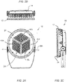
- an LED lighting unit 10 which includes a solid state LED array assembly, e.g., an LED array assembly 13, positioned and oriented at a front of the lighting unit 10, and a power supply assembly 15, positioned at a rear of the lighting unit 10, coupled to but located directly behind the LED array assembly 13.
- the LED array assembly 13 and the power supply assembly 15 of the illustrative embodiment are both generally cylindrical in shape, that is, are of generally circular cross section with a diameter greater than their respective heights and/or thicknesses.
- the LED assembly 13 includes a solid-state array housing including, for example LED lighting elements, referred to herein as an LED array housing 12.
- the LED array housing 12 has a front diameter of approximately 17.25 inches and tapers to a rear side diameter of approximately 15.6 inches over a total housing thickness of approximately 3.25 inches.
- the power supply assembly 15 includes a power supply housing 14, which is spaced apart from a rear surface of the LED array housing 12, for example, by approximately 1.75 inches having a front diameter of approximately 14.9 inches and tapering to a rear side diameter of approximately 14.25 inches over a thickness of approximately 2.8 inches.
- Both the LED array housing 12 and the power supply housing 14 include a thermally conductive and supportive material, such as cast aluminum, for example, having a wall thickness of about 0.25 to 0.5 inches, provided with a polyester powder coat finish and sealed according to International Safety Standard IP66.
- the cross sectional shapes of the array housing 12 and the power supply housing 14 are generally defined by the shape of the LED array, which is described in detail in a following description, as are the dimensions of the LED array housing 12 and the power supply housing 14. It will also be understood that other cross sectional and longitudinal shapes, such as square, rectangular or polygonal for example, are possible and fall within the scope of the present invention.
- the lighting unit 10 is typically supported by a conventional mounting bracket 16 which allows for adjustment of the lighting unit as may be beneficial in causing or otherwise directing illumination in a preferred direction.
- the mounting bracket 16 can allow for vertical rotation of the lighting unit 10 about a horizontal axis HA, which passes through the lighting unit 10 at a location approximately centrally between the LED array housing 12 and the power supply housing 14 at approximately a center of balance of the lighting unit 10.
- the mounting bracket 16 can allow for horizontal rotation about a vertical axis VA. It will be understood, however, that a lighting unit 10 may be supported or mounted by any of a wide range of other conventional mounting designs and/or configuration, including both fixed mounts and positional mounts of various types.
- a power/control cable 18 supplies power and control signals to the LED array and enters the lighting unit 10 though a conventional weather tight fitting 20 that is mounted in a side wall of the power supply housing 14 (see FIG. 2F ).
- the power/control cable 18 may include separate power and control cables or a single combined power and control cable.
- the power cable 18 may enter power supply housing 14 through the power cable fitting 20 while the control cable may enter through a side or a rear wall of the LED array housing 12 via a separate control cable fitting (not shown).
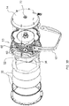
- the LED array housing 12 is shown as being generally frusto-conical in shape, and may also be cylindrical in shape, with a generally circular transverse cross section having a diameter greater than the axial length of the LED array housing 12 and a circumferential side wall 22 that gradually slopes from its full diameter, at the front face 24 of the LED array housing 12, to a smaller diameter forming the rear surface 26 of the LED array housing 12.
- the LED array assembly 13 includes a solid state array module, e.g., an LED array 28 including a symmetrically packed array of solid state lighting elements, e.g., LEDs 30 mounted on one or more printed circuit modules 42a, 42b, 42c (generally 42) for generating and forming a desired light beam to be generated and transmitted by the lighting unit 10, when powered, with the LED array 28 being covered and protected by one or more optical/sealing elements 32, such as a transparent lens.
- the optical/sealing element(s) 32 sealing mate with ( FIG.
- optical/sealing elements 32 may include a beam shaping lens(es), an optical filter(s) of various types, an optical mask(s), a protective transparent cover plate(s), etc.
- the power supply housing 14 in turn, contains a power supply 34 that is connected with the power leads of the power/control cable 18 and supplies electrical power outputs to the LED array 28, as discussed in further detail below.
- each of the individual LEDs 30 of the LED array 28 is mounted on a front surface 36 of a printed circuit board 38 (see generally FIGs. 1A , 2A and 3A ) that sized and shaped to be accommodated and mounted within the interior compartment 40 defined by the LED array housing 12, i.e., in close abutting and intimate contact with the bottom surface 26 of the LED array housing 12 to facilitate heat transfer thereto.
- the LEDs 30 include any desired and selected combination of high powered LEDs, such as red, green, blue or white LEDs of various color temperatures, such as 2,700K, 3,000K and/or 4,000K white light LEDs, depending upon the desired output spectrum or spectrums of the LED lighting unit 10.
- the LED array 28 includes three separate groups, channels or arrays each including a total of 36 LEDs.
- the 36 LEDs of each separate group, channel or array are arranged in a 6 x 6 LED array 42 generally in the shape of a diamond.
- Each one of the three diamond shaped 6 x 6 LED arrays 42 are clustered together closely adjacent one another to thereby form a generally hexagonally shaped LED array 28, as shown in FIG. 3A , of 108 LEDs (se e FIGs. 1A and 2A , for example).
- the three separate diamond shaped arrays 42 are located closely adjacent one another and are capable of providing approximately 9,000 lumens of total illumination at 150 watts power consumption with an output beam having a radiating angle of between 6° and 30°, that is, radiating angle somewhere between a narrow spotlight beam and a floodlight beam, depending upon the selection, type and the arrangement of LEDs 30, as described below, as well as the utilized optical elements 32.
- the LED lighting unit 10 may be constructed with either more or less than 108 LEDs, depending upon the particular illumination application, with any desired combination of LED output colors, e.g., such as red, blue, green, amber, cyan, royal blue, yellow, warm white and cool white, and with greater or lesser output power and power consumption by suitable adaptation of the embodiments described herein, as will be readily understood by and be apparent to those of ordinary skill in the relevant art.
- LED output colors e.g., such as red, blue, green, amber, cyan, royal blue, yellow, warm white and cool white
- the color or the color temperature output of the LED array 28 may include any desired color combination of LEDs 30 and may be controlled by a dimmer control for the LEDs 30, forming the LED array 28, so that the relative illumination level output of, the individual LEDs 30 in the array, combine to provide the desired color or color temperature for the lighting unit output.
- the dimming control of the individual LEDs 30, forming the LED array 28 can be provided by one or more control circuits 44, which are controlled by signals transmitted to each LED lighting unit 10 through the control/power cable 18 according to industry standard protocols, such as and for example, the industry standard DMX512 protocol, the DALI protocol, the digital signal interface (DSI), or the remote device management (RDM) protocol.
- Such control circuits 44 can be integrated, for example, in the one or more circuit boards 38 of the LED array assembly 13.
- the control circuits 44 for the LEDs 30 of the LED array 28 are mounted on the front surface 36 of the circuit board 38 and are generally disposed circumferentially about the LED array 28.
- the control leads (not shown), which connect the control outputs of the control circuits 44 to the individual LEDs 30, can also be formed on the front surface 36 of the printed circuit board 38.
- the power leads (not shown), which connect the power output of the power supply 34 in power supply housing 14 to the control circuits 44 and the LEDs 30, are also coupled to the front surface 36 of the printed circuit board 38 for suitable powering of the various that the LEDs 30.
- the rear surface 26 of the LED array housing 12 generally includes a thermally conductive heat transfer element 50.
- a rear surface 52 of the printed circuit board 38 is generally provided in intimate contact with the heat transfer element 50 so as to facilitate conduction of the heat, generated by the LEDs 30, from the circuit board 38 and into the heat transfer element 50 for subsequent transferred to surrounding air, as will be discussed below in further detail.
- the printed circuit board 38, supporting the LED array 28 generally absorbs, transfers and/or otherwise carries away the heat which is generated by the LEDs 30. Accordingly, in such embodiments it is important that the rear surface 52 of the printed circuit board 38 be in thermally conductive contact with the adjacent surface of the heat transfer element 50.
- the heat transfer element 50 is preferably manufactured from a thermally conductive material, such as aluminum or similar material or metal which readily conducts heat.
- a thermally conductive material such as aluminum or similar material or metal which readily conducts heat.
- the LED array housing 12 is mounted to the power supply housing 14 via three or more perimeter support posts 54, e.g., typically between three and eight and preferably about 4 to 6 support posts 54, that extend between and interconnect the LED array housing 12 with the power supply housing 14.
- Each support post 54 of the example embodiment has a threaded recess, in a free remote end thereof, while the power supply housing 14 as a mating aperture, which permits a conventional threaded fastener to pass through the mating aperture to threadedly engage the threaded recess of the support post 54, thereby fixedly connecting the two housings to one another.
- the support posts 54 are spaced about the periphery of the heat transfer element 50 so as not to hinder, as will be discussed below in further detail, the airflow through and along the heat transfer element 50.
- support posts 54 generally mechanically connect and secure the LED array housing 12 to the power supply housing 14 while also preventing the direct conduction of heat from the LED array housing 12 to the power supply housing 14, or vice versa. That is, the support posts 54 of the LED lighting unit 10 are designed to minimize the transfer of heat from the LED array housing 12 to the power supply housing 14. Accordingly, the support posts 54 include one or more conventional thermally isolating elements or components, for example, and/or may have a reduced diameter end which minimizes the heat transfer capacity along the support post 54 to the power supply housing 14. Minimum lengths of the one or more support posts 54 are generally sufficient to maintain at least some degree of physical separation between the LED array housing 12 and the power supply housing 14.
- a cable conduit 56 also extends between the LED array housing 12 and the power supply housing 14.
- Such a cable conduit 56 generally includes a hollow internal passage, which facilitates the passage of associated leads or electrical wires between the power supply 34 and/or the control circuitry of LED array 28.
- the rear surface 26 of the LED array housing 12 is provided with multiple generally parallel extending heat dissipation elements 60, e.g., generally twelve spaced apart elongate members or ridges, which project into an airflow space 62 formed between the rear surface 26 of the LED array housing 12 and the front surface 58 of the power supply housing 14. As shown in FIG.
- the two outer most heat dissipation elements 60 are both continuous and extend generally parallel to one another, from one lateral side to the opposite lateral side of the LED lighting unit 10, while the inner heat dissipation elements 60, located therebetween, are each discontinuous and generally extend radially inward and toward a central axis A of the LED lighting unit 10 which extends normal to the rear surface 26 of the LED array housing 12.
- Such arrangement of the inner heat dissipation elements 60 has a tendency of channeling and/or directing air radially inwardly and toward the central region of the airflow space 62, i.e., toward the central axis A, between the rear surface 26 of the LED array housing 12 and the front surface 58 of the power supply housing 14.
- Each of the heat dissipation elements 60 of the illustrative example generally has the shape of a rectangular member or ridge, which extends radially inward into and provides access to the airflow space 62.
- Each generally rectangular shaped heat dissipation element 60 is thickest at its base where it is integrally connected with the rear surface 26 of the LED array housing 12 but becomes gradually thinner as the heat dissipation element 60 projects away from the base, extending upwards toward the power supply housing 14. It is to be appreciated that the heat dissipation elements 60 generally do not contact, but are each spaced from, the front surface 58 of the power supply housing 14 so as to avoid transferring or conducting heat thereto.
- the exposed peripheral edges of the heat dissipation elements 60 are generally smooth and/or rounded so as to allow the air to flow around and by those edges without causing undue turbulence to the air which, in turn, assists with increasing the airflow through the airflow space 62 and dissipation or removal of heat from heat dissipation elements 60 of the heat transfer element 50.
- the heat dissipation elements 60 each generally extend from the rear surface 26 of the LED array housing 12 and toward the front surface 58 of the power supply housing 14 but are slightly spaced from the front surface 58 of the power supply housing 14, e.g., are spaced therefrom by a distance of about 0.25 inches or less, thereby forming a thermal isolation gap which thermally isolates the LED array housing 12 from the power supply housing 14 and significantly reduces the direct transfer of heat from the LED array housing 12, supporting the electrically powered LED array 28, to the power supply housing 14 containing the power supply 34.
- thermal conductivity between the heat dissipation elements 60 and the power supply housing 14 may also be reduced while allowing the heat dissipation elements 60 to be in contact with the power supply housing 14 by, for example, minimizing the surface contact area between each heat dissipation element 60 and the power supply housing 14 or by interposing a thermal isolation element, such as a thermally non-conductive spacer, between the leading edge of each heat dissipation element 60 and front surface 58 of the power supply housing 14.
- a thermal isolation element such as a thermally non-conductive spacer
- the heat dissipation elements 60, the rear surface 26 of the LED array housing 12 and the adjacent front surface 58 of the power supply housing 14 together form multiple convective inlet passages 66 which allow inlet of convective airflow into the airflow space 62, which can remove heat from by the heat dissipation elements 60 during operation of the LED lighting unit 10, as will be discussed below.
- the effectiveness and efficiency of this convective heat transfer is, as is well understood by those of skill in the relevant art, a function of the interior dimensions, the lengths and the number of convective circulation passages 66, as well as the surface characteristics of the heat dissipation elements 60, the rear surface 26 of the LED array housing 12 and the front surface 58 of the power supply housing 14.
- the interior dimensions and the lengths and the characteristics of the interior surfaces of the convective inlet passages 66 as well as the shape or contour of the airflow space 62 determines the type, the velocity and the volume of the convective airflow that is allowed to flow into the convective inlet passages 66.
- each convective inlet passage 66 is generally defined by a pair of adjacent heat dissipation elements 60 located on either side thereof as well as the rear surface 26 of the LED array housing 12 and the front surface 58 of the power supply housing 14. Accordingly, each heat dissipation passage 66 generally has a width of between approximately 0.3 to 1.5 inches preferable about 0.75 inches, a height of between approximately 1.0 to 2.0 inches preferable about 1.5 inches, and a length ranging between approximately 1.0 to 4.5 inches preferable about 3.25 inches or so, depending upon the location of the passage 66.
- the heat dissipation elements 60 thereby provide a desired heat dissipation area for dissipating heat generated by the LED array 28 and transferred to the rear surface 26 of the LED array housing 12 while the non-conductive thermal isolation gaps 64, between the remote free ends of the heat dissipation elements 60 and the front surface 58 of the power supply housing 14, significantly reduce the transfer of any heat directly from the LED array housing 12 to the power supply housing 14 and thereby significantly reducing adverse mutual heating effects of the LED array 28 to the power supply 34.
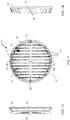
- the rear surface 26 of the LED array housing 12 also accommodates multiple spaced apart generally cylindrical or conical pins 68 in addition to the generally rectangular shaped heat dissipation elements 60.
- the rear surface 26 accommodates typically between 20 and 500 pins, more preferably between 100 and 300 pins, preferably about 206 pins (see FIG. 4 ), which extend generally normal to the rear surface 26 of the LED array housing 12.
- Each one of these cylindrical or conical pins 68 is generally uniformly spaced from each adjacent pin 68 and cooperates with the heat dissipation elements 60 to maximize a random convection airflow through the airflow space 62 as well as heat transfer from the cylindrical or conical pins 68 to the air so as to maximize cooling of the LED lighting unit 10.
- each pin 68 is generally cylindrical in shape and has a diameter of between approximately 0.3 to 0.65 inches preferable about 0.35 inches and a height of between approximately 0.6 to 1.75 inches, preferable between about 0.9 and 1.5 inches. It is to be appreciated that the somewhat thinner pins 68 tend to provide more efficient transfer of the heat from the LED array housing 12 to the air than thicker pins 68 which tend to be less efficient.
- Each of the heat dissipation elements 60 has an approximate height of between approximately 0.6 to 1.75 inches, preferable between about 0.9 and 1.5 inches, measured relative to the rear surface 26 of the LED array housing 12, a width or thickness of approximately 0.25 to 0.45 inches, preferably about 0.4 inches, of an inch tapering or narrowing in a direction away from the rear surface 26, for example, with the taper being approximately 6°, and a length ranging from about 2 to 10 inches, depending upon their location across the diameter of the LED array housing 12, and may be spaced apart by a distance on the order of 1.0 to 1.5, preferably about 1.35 inches or so. As generally shown in FIG.
- the rear wall of the LED housing 12 may be domed or otherwise crowned so as to be located slightly closer to the front surface of the power source housing 14, i.e., decrease the height of the airflow space, and this configuration facilitates accelerating of the air as the air flows through the airflow space 62.
- the chimney 70 which is formed in and extends through the power supply housing 14. As shown, the chimney 70 extends from the front surface 58 of the power supply housing 14 to the rear surface of the power supply housing 14 and thus forms a through opening 72 through a central region of the power supply housing 14.
- the chimney 70 includes first and second conically shaped sections 74, 76 which join with one another at a generally narrower throat section 78.
- each one of the first and second conically shaped sections 74, 76 generally has a wider diameter at either the front surface 58 (e.g., having a diameter of between 1.0 inches to 2.5 inches, preferably about 2.12 inches) or the rear surface of the power supply housing 14 (e.g., having a diameter of between 1.0 inches to 2.5 inches, preferably about 1.94 inches) and a narrower diameter at the throat section 78 (e.g., having a diameter of between 0.75 inches to 1.5 inches, preferably about 1.0 to 1.2 inches).
- the chimney 70 is generally concentric with the central axis A of the LED lighting unit 10 as such positioning generally improves the airflow into and through the LED lighting unit 10.
- a central region of the heat transfer element 50 includes three arcuate walls 80 to assist with directing airflow into the chimney. These three arcuate walls 80 generally are arranged in an interrupted circle and are generally concentric with both the longitudinal axis A and the chimney 70.
- Six centrally located pins 68 are located within a region defined by the three arcuate walls 80 and these six pins 68 are generally separated from the remaining pins 68 by the three arcuate walls 80. These six centrally located pins 68 are in intimate communication with air for such air is directed into the chimney 70.
- the LEDs 30 During operation of the LED lighting unit 10, the LEDs 30 generate heat which is conducted to and through the printed circuit board 38 and into the rear surface 26 of the LED array housing 12. As the heat transfer element 50 absorbs heat, ambient air naturally begins to flow into and through each one of the convective inlet passages 66 and into the airflow space 62 located between the rear surface 26 of the LED array housing 12 and the front surface 58 of the power supply housing 14. As this ambient air flows in through each one of the convective inlet passages 66 from a peripheral space between the rear surface 26 of the LED array housing 12 and the front surface 58 of the power supply housing 14, the air generally directed radially inwardly toward the central axis A of the LED lighting unit 10.
- the air contacts with the exterior surface of the rectangular heat dissipation elements 60 and the heat is readily transferred from the rectangular heat dissipation element 60 to the air.
- Such heat transfer in effect cools the rectangular heat dissipation element 60 so that such elements may in turn conduct additional heat away from the LEDs 30.
- the air continues to flow radially inward, the air contacts one or more of the pins 68 and, as a result of such contact, additional heat is transferred from the pins 68 to the air which further increases the temperature of the air while simultaneously cooling the pins 68.
- the heated air generally reaches the central axis A, the heated air communicates with the three accurate walls and the six centrally located pins 68 before flowing into the chimney 70 and thus flowing axially along the central axis A and through the chimney 70 and out through the rear surface of the power supply housing 14.
- This airflow pattern, from the convective inlet passages 66 through the airflow space 62 and out through the chimney 70 maximizes convection airflow through the LED lighting unit 10 and thus achieves maximum cooling of the LED lighting unit 10.
- the average temperature readings for four (4) different locations of the LED lighting unit 10, according to the first embodiment discussed above, are shown.
- the average temperature for the rear surface of the LED lighting unit 10 is typically about 96.0°C
- the average temperature at the outer edge of one of the rectangular heat dissipation element 60 of the LED lighting unit 10 is typically about 102.3°C
- the average temperature for the front surface 36 of the circuit board of the LED lighting unit 10 is typically about 80.7°C
- the average temperature for the outer circumference edge of the front surface 24 of the LED array housing 12 is typically about 98.4°C. It is to be appreciated that this arrangement generally provides particularly efficient cooling of the LEDs 30 as well as the internal circuitry of the LED lighting unit 10.
- FIGs. 7, 7A and 7B a second alternative embodiment of a heat transfer element 50' will now be described. As this second embodiment is similar to the first embodiment in many respects, only the differences between the second embodiment and the first embodiment will be discussed in detail.
- a rear surface 26' of the LED array housing 12' is provided with multiple generally parallel extending heat dissipation elements 60', e.g., generally twelve spaced apart elongate members 60', which project into elongated airflow spaces 62' disposed between the rear surface 26' of the LED array housing 12' and the front surface 58 of the power supply housing 14.
- Each one of the heat dissipation elements 60' generally extends parallel to one another from one lateral side to the opposite lateral side.
- each one of the heat dissipation elements 60' is interrupted at mid section, thus forming an elongate channel 82.
- This elongate channel 82 extends normal to each one of the heat dissipation elements 60' and is coincident with a diameter of the LED lighting unit 10 which is also coincident with the central axis A of the LED lighting unit 10.
- Such arrangement of the heat dissipation elements 60' has a tendency of directing air radially inwardly and toward the elongate channel 82 where the air can then be directed radially outwardly along the elongate channel 82, i.e., in both directions along the elongate channel 82 away from the central axis A, and thus out of the airflow space 62' defined between the rear surface 26' of the LED array housing 12' and the front surface 58 of the power supply housing 14.
- this arrangement is somewhat useful in the event that a chimney 70 is not provided in the rear surface of the power supply housing 14.
- this embodiment of the heat transfer element 50' can be used in combination with a chimney 70 so that the air enters along both lateral sides of the LED lighting unit 10, flows along the heat dissipation elements 60' and is eventually exhausted up through the chimney 70 provided in the power supply housing 14.
- FIG. 8 a third alternative version of the heat transfer element 50' will now be described. As this third embodiment is similar to the second embodiment in many respects, only the differences between the third embodiment and the second embodiment will be discussed in detail.
- the rear surface 26" of the LED array housing 12" is provided with multiple generally parallel extending heat dissipation elements 60", e.g., generally twelve spaced apart elongate members, which project into the airflow space 62" formed between the rear surface 26" of the LED array housing 12" and the front surface 58 of the power supply housing 14.
- Each one of the heat dissipation elements 60" generally extends parallel to one another from one lateral side to the opposite lateral side.
- Such arrangement of the heat dissipation elements 60" has a tendency of directing air from one lateral side to the opposite lateral side where the air can then be directed outward from the airflow space 62" defined between the rear surface 26 of the LED array housing 12" and the front surface 58 of the power supply housing 14.
- This arrangement is somewhat useful in the event that a chimney 70 is not provided in the rear surface of the power supply housing 14.
- this embodiment of the heat transfer element 50" can be used in combination with a chimney 70 so that the air enters from both lateral sides of the LED lighting unit 10, flows along the heat dissipation elements 60" and is eventually exhausted up through the chimney 70 provided in the power supply housing 14.
- FIG. 9A and 9B are respectively cross sectional schematic views of an embodiment of the LED lighting unit 100 positionable between downward ( FIG. 9A ) lighting and lateral ( FIG. 9B ) lighting applications. Such positioning can be accomplished, for example, with the standard mounting bracket can allow for vertical rotation of the lighting unit 100 about a horizontal axis HA (e.g., FIG. 1B ).
- the LED lighting unit 100 includes an LED array housing 112 projecting illumination 102 in a preferred direction as shown.
- a heat transfer element 150 is mounted to a rear surface of the LED array housing 112, configured to draw heat away from internal lighting elements.
- the LED lighting unit 100 also includes a separate power supply housing 114 positioned in an overlapping, spaced-apart arrangement with the LED array housing 112. An airflow space 162 is defined between overlap of the two separate housings 112, 114.
- the power supply housing 114 includes a centrally located lumen, or chimney 70 extending through the power supply housing 114.
- the heat transfer element 150 heats air within the airflow space 162, creating an upward draft through the chimney 170, as shown.
- the upward draft draws cooler ambient air laterally into the airflow space 162, which results in a continual cooling of the LED lighting unit 100.
- the heat transfer element 150 When positioned for lateral illumination as shown in FIG. 9B , the heat transfer element heats air within the airflow space 162, creating an upward draft. Instead of being directed through the chimney 170, however, the heated air exits the airflow space 162 from a top portion of the void between the LED array housing and the power supply housing 114.
- the heat transfer element 150 includes vertical passageways, such as flutes or openings between ridges and/or pins that are largely unobstructed to promote a draft according to the direction indicated by the arrows.
- cooling can be enhanced by a combination of a portion of air heated within the airflow space 162 exiting through the chimney 170 and a portion exiting at an upper lateral region or edge of the airflow space 162. As the warm air naturally rises, the heated air will rise creating a draft drawing in cooler, ambient air at least through a lower lateral region or edge of the airflow space 162.
- FIG. 10 is a cross sectional schematic view of an alternative embodiment of an LED lighting unit 200 for upward illumination.
- the LED lighting unit 200 includes an LED array housing 212 projecting illumination 202 in a preferred direction as shown.
- a heat transfer element 250 is mounted to a rear surface of the LED array housing 212, configured to draw heat away from internal lighting elements.
- the LED lighting unit 200 also includes a separate power supply housing 214 positioned in an overlapping, spaced-apart arrangement with the LED array housing 212.
- An airflow space 262 is defined between overlap of the two separate housings 212, 214.
- the LED array housing 212 includes a centrally located lumen, or chimney 272 extending through the LED array housing 212.
- the chimney 272 can take on any of various shapes, such as cylindrical, frusto-conical, and the other various chimney configurations described herein in relation to the power supply housing 14.
- the heat transfer element 250 heats air within the airflow space 262, creating an upward draft through the chimney 272, as shown.
- the upward draft draws cooler ambient air laterally into the airflow space 262, which results in a continual cooling of the LED lighting unit 200.
- FIG. 11 is a cross sectional schematic view of another alternative embodiment of an LED lighting unit 300 including two chimneys 370, 372.
- a heat transfer element 350 heats air within an airflow space 362 located between a rear surface of the LED array housing 314 and a front surface of the power supply housing 314.
- a first chimney 370 is provided through the power supply housing 314 as described in relation to FIG. 9A .
- a second chimney 372 is provided through the LED array housing 312 as described in relation to FIG. 10 .
- the LED lighting unit 300 can provide unassisted cooling in either upward, downward or lateral illumination positions.
Landscapes
- Engineering & Computer Science (AREA)
- General Engineering & Computer Science (AREA)
- Arrangement Of Elements, Cooling, Sealing, Or The Like Of Lighting Devices (AREA)
- Non-Portable Lighting Devices Or Systems Thereof (AREA)
- Illuminated Signs And Luminous Advertising (AREA)
Claims (10)
- Festkörperbeleuchtungseinheit (10), die Folgendes umfasst:ein Festkörperanordnungsgehäuse (12), das ein Innenfach (40) definiert;mindestens ein Festkörperanordnungsmodul (28), das Folgendes umfasst: eine Anordnung von Festkörperbeleuchtungselementen (30); eine Steuerschaltung (44) des Festkörperbeleuchtungselements und eine Leiterplatte (38), wobei das Festkörperanordnungsmodul in dem Innenfach des Festkörperanordnungsgehäuses untergebracht ist;eine hintere Fläche (26) des Festkörperanordnungsgehäuses, die ein Wärmeübertragungselement (50) umfasst; undein Stromversorgungsgehäuse (14), das eine Stromversorgung (34) aufnimmt, wobei das Stromversorgungsgehäuse eine vordere Fläche (58) aufweist, die der hinteren Fläche des Festkörperanordnungsgehäuses gegenüberliegt und einen Luftkanal (70) aufweist, der sich von der vorderen Fläche des Stromversorgungsgehäuses zu einer hinteren Fläche davon durch es erstreckt,wobei die hintere Fläche des Festkörperanordnungsgehäuses fest in einer beabstandeten Beziehung in Bezug auf die vordere Fläche des Stromversorgungsgehäuses angeordnet ist, so dass ein Eingangsluftströmungsraum (62) dazwischen definiert wird, so dass während des Betriebs der Festkörperbeleuchtungseinheit Umgebungsluft radial nach innen zur zentralen Beleuchtungsachse hin in den Eingangsluftströmungsraum und zu der zentralen Beleuchtungsachse der Festkörperbeleuchtungseinheit strömt und axial entlang der Mittelachse und durch den Luftkanal austritt, um das Abführen von Wärme von den Festkörperbeleuchtungselementen zu ermöglichen, dadurch gekennzeichnet, dass der Luftkanal ein Lumen (72) umfasst, das entlang der zentralen Beleuchtungsachse ausgerichtet ist, wobei das Lumen Folgendes umfasst: ein erstes konisch geformtes Lumen (74), dessen Basis der hinteren Fläche des Festkörperanordnungsgehäuses zugewandt ist, und ein zweites konisch geformtes Lumen (76), dessen Basis der hinteren Fläche des Stromversorgungsgehäuses zugewandt ist, wobei das erste und das zweite konisch geformte Lumen entlang eines allgemein schmaleren Halsteils (78) miteinander verbunden sind.
- Beleuchtungseinheit nach Anspruch 1, wobei die Anordnung von Festkörperbeleuchtungselementen (30) und die Steuerschaltung (44) des Festkörperbeleuchtungselements auf einer ersten Fläche (36) der Leiterplatte (38) angebracht sind.
- Beleuchtungseinheit nach Anspruch 1, wobei die Anordnung von Festkörperbeleuchtungselementen (30) eine eng beabstandete Anordnung von lichtemittierenden Dioden (LEDs) umfasst.
- Beleuchtungseinheit nach Anspruch 1, die ferner mindestens eine transparente Linse zum Abdichten des Innenfachs (32) umfasst.
- Beleuchtungseinheit nach Anspruch 1, wobei das Festkörperanordnungsgehäuse (12) und das Stromversorgungsgehäuse (14) im Wesentlichen entlang einer zentralen Beleuchtungsachse zueinander ausgerichtet sind und einen im Wesentlichen gleichmäßigem Abstand dazwischen aufweisen.
- Beleuchtungseinheit nach Anspruch 1, wobei das Wärmeübertragungselement (50) mehrere vorstehende Merkmale (60) umfasst, die sich von der hinteren Fläche (26) des Festkörperanordnungsgehäuses (12) weg zu der vorderen Fläche (58) des Stromversorgungsgehäuses (14) hin erstrecken und physikalisch von dem Stromversorgungsgehäuse getrennt bleiben.
- Beleuchtungseinheit nach Anspruch 6, wobei die Vielzahl vorstehender Merkmale (60) mehrere vorstehende Rippen umfasst, die Luftströmungskanäle dazwischen definieren, wobei die Vielzahl von Rippen von dem Stromversorgungsgehäuse durch einen thermischen Isolationsspalt (64) getrennt ist.
- Beleuchtungseinheit nach Anspruch 7, wobei die Rippen im Wesentlichen linear sind und sich über die hintere Fläche (26) des Festkörperanordnungsgehäuses (12) erstrecken, wobei freiliegende Enden der Rippen konvektive Eintrittskanäle (66) definieren.
- Beleuchtungseinheit nach Anspruch 1, die ferner eine Vielzahl von Stützpfosten (54) umfasst, die fest zwischen der hinteren Fläche (26) des Festkörperanordnungsgehäuses (12) und der vorderen Fläche (58) des Stromversorgungsgehäuses (14) angebracht sind.
- Beleuchtungseinheit nach Anspruch 1, wobei jeder Stützpfosten der Vielzahl von Stützpfosten (54) ein thermisch isolierendes Merkmal umfasst, um die Wärmeleitung zwischen dem Festkörperanordnungsgehäuse (12) und dem Stromversorgungsgehäuse (14) zu hemmen.
Applications Claiming Priority (3)
| Application Number | Priority Date | Filing Date | Title |
|---|---|---|---|
| US201161485904P | 2011-05-13 | 2011-05-13 | |
| US13/345,030 US8485691B2 (en) | 2011-05-13 | 2012-01-06 | High powered light emitting diode lighting unit |
| PCT/US2012/037286 WO2012158454A2 (en) | 2011-05-13 | 2012-05-10 | High powered light emitting diode lighting unit |
Publications (3)
| Publication Number | Publication Date |
|---|---|
| EP2707652A2 EP2707652A2 (de) | 2014-03-19 |
| EP2707652A4 EP2707652A4 (de) | 2014-11-12 |
| EP2707652B1 true EP2707652B1 (de) | 2017-01-04 |
Family
ID=47141746
Family Applications (1)
| Application Number | Title | Priority Date | Filing Date |
|---|---|---|---|
| EP12786058.3A Active EP2707652B1 (de) | 2011-05-13 | 2012-05-10 | Hochenergetische led-beleuchtungseinheit |
Country Status (5)
| Country | Link |
|---|---|
| US (3) | US8459833B2 (de) |
| EP (1) | EP2707652B1 (de) |
| CA (2) | CA2833647C (de) |
| ES (1) | ES2617702T3 (de) |
| WO (2) | WO2012158454A2 (de) |
Families Citing this family (54)
| Publication number | Priority date | Publication date | Assignee | Title |
|---|---|---|---|---|
| USD677815S1 (en) * | 2011-08-24 | 2013-03-12 | Fuzhou F&V Photographic Equipment Co., Ltd. | LED spot light for camera |
| EP2828573B1 (de) * | 2012-03-18 | 2017-05-10 | Robe Lighting, Inc | Verbessertes kollimationssystem für eine led-leuchte |
| USD728849S1 (en) | 2012-05-03 | 2015-05-05 | Lumenpulse Lighting Inc. | LED projection fixture |
| US8950893B2 (en) * | 2013-02-06 | 2015-02-10 | Kason Industries, Inc. | LED light |
| CN203298069U (zh) * | 2013-03-05 | 2013-11-20 | 深圳市耀嵘科技有限公司 | 一种led墙角灯 |
| DE102014000582A1 (de) * | 2013-09-17 | 2015-03-19 | Dietmar Friedrich Brück | Licht aussendende Einrichtung |
| CN103604074A (zh) * | 2013-11-28 | 2014-02-26 | 常州市武进区半导体照明应用技术研究院 | 一种建材灯 |
| US10408402B2 (en) | 2014-03-10 | 2019-09-10 | Robe Lighting S.R.O. | Optical system for a LED luminaire |
| DE102014004762B4 (de) * | 2014-03-28 | 2023-01-26 | Phoenix Mecano Digital Elektronik Gmbh | LED-Umrüstsatz für Außenleuchten |
| US11128179B2 (en) | 2014-05-14 | 2021-09-21 | California Institute Of Technology | Large-scale space-based solar power station: power transmission using steerable beams |
| US10144533B2 (en) | 2014-05-14 | 2018-12-04 | California Institute Of Technology | Large-scale space-based solar power station: multi-scale modular space power |
| US12021162B2 (en) | 2014-06-02 | 2024-06-25 | California Institute Of Technology | Ultralight photovoltaic power generation tiles |
| WO2015187739A1 (en) | 2014-06-02 | 2015-12-10 | California Institute Of Technology | Large-scale space-based solar power station: efficient power generation tiles |
| US10107484B2 (en) * | 2014-10-24 | 2018-10-23 | Jennifer Moyers | Lawn mower light |
| EP3051205B1 (de) * | 2015-02-02 | 2017-05-24 | LG Electronics Inc. | Beleuchtungsvorrichtung |
| WO2016126964A1 (en) | 2015-02-04 | 2016-08-11 | Milwaukee Electric Tool Corporation | Light |
| US10101017B2 (en) | 2015-02-04 | 2018-10-16 | GE Lighting Solutions, LLC | LED luminaire with internal heatsink |
| US20170074489A1 (en) * | 2015-03-16 | 2017-03-16 | Pavel Jurik | System and method for controlling light output in a led luminaire |
| US10544928B2 (en) | 2015-04-17 | 2020-01-28 | Hubbell Incorporated | Emergency exit light |
| US10775032B2 (en) | 2015-07-01 | 2020-09-15 | Milwaukee Electric Tool Corporation | Area light |
| WO2017015508A1 (en) | 2015-07-22 | 2017-01-26 | California Institute Of Technology | Large-area structures for compact packaging |
| US10454565B2 (en) | 2015-08-10 | 2019-10-22 | California Institute Of Technology | Systems and methods for performing shape estimation using sun sensors in large-scale space-based solar power stations |
| US10992253B2 (en) | 2015-08-10 | 2021-04-27 | California Institute Of Technology | Compactable power generation arrays |
| US10323831B2 (en) | 2015-11-13 | 2019-06-18 | Milwaukee Electric Tool Corporation | Utility mount light |
| US10161619B2 (en) * | 2015-12-28 | 2018-12-25 | Eaton Intelligent Power Limited | LED illumination device with vent to heat sink |
| US10066805B1 (en) * | 2016-02-29 | 2018-09-04 | Optronics International, Llc | Multi-function vehicle light assembly |
| AU201612461S (en) * | 2016-04-13 | 2016-06-02 | Shenzhen Kinglumi K&L Photoelectric Tech Co | Lamp |
| EP4236630A3 (de) | 2016-04-22 | 2023-10-11 | Nanogrid Limited.(HK) | Systeme und verfahren zum verbinden und steuern von konfigurierbaren beleuchtungseinheiten |
| USD816252S1 (en) | 2016-05-16 | 2018-04-24 | Milwaukee Electric Tool Corporation | Light |
| CN109154656B (zh) * | 2016-05-19 | 2023-08-25 | 哈曼国际工业有限公司 | 具有可见反馈的支持姿势的音频装置 |
| US10794583B2 (en) * | 2017-04-20 | 2020-10-06 | Insight Lighting, Inc. | Floodlight heat transfer system |
| CA3062286A1 (en) | 2017-05-06 | 2018-11-15 | Hubbell Incorporated | Wall pack light fixtures |
| US11887449B2 (en) * | 2017-07-13 | 2024-01-30 | Elvis Maksuti | Programmable infrared security system |
| CN107426866B (zh) * | 2017-07-24 | 2019-12-17 | 广州市雅江光电设备有限公司 | 一种运用于led灯具的温度-功率控制方法 |
| USD1120426S1 (en) * | 2018-04-30 | 2026-03-24 | HLI Solutions, Inc. | Lighting fixture |
| US11634240B2 (en) | 2018-07-17 | 2023-04-25 | California Institute Of Technology | Coilable thin-walled longerons and coilable structures implementing longerons and methods for their manufacture and coiling |
| WO2020037324A1 (en) * | 2018-08-17 | 2020-02-20 | Sportsbeams Lighting, Inc. | Sports light having single multi-function body |
| FR3087720B1 (fr) * | 2018-10-29 | 2023-03-17 | Valeo Vision | Module lumineux pour vehicule automobile |
| US11772826B2 (en) | 2018-10-31 | 2023-10-03 | California Institute Of Technology | Actively controlled spacecraft deployment mechanism |
| USD921256S1 (en) * | 2018-11-28 | 2021-06-01 | Shenzhen Huadian Lighting Co., Ltd. | LED stadium light |
| USD1060803S1 (en) * | 2019-07-31 | 2025-02-04 | Sportsbeams Lighting, Inc. | Sports venue light |
| EP3987228A4 (de) * | 2019-09-12 | 2023-07-26 | Milwaukee Electric Tool Corporation | Licht unterhalb eines fahrgestells |
| USD956302S1 (en) * | 2020-06-19 | 2022-06-28 | Shenzhen Snc Opto Electronic Co., Ltd. | LED lamp |
| USD1018931S1 (en) * | 2020-07-27 | 2024-03-19 | Guangzhou Forda Signal Co., Ltd | Work lamp |
| US20220214030A1 (en) * | 2021-01-07 | 2022-07-07 | GVM Photographic Equipment Inc. | Stick-On Lamp Board and Uses Thereof |
| USD1007750S1 (en) | 2021-01-15 | 2023-12-12 | Milwaukee Electric Tool Corporation | Adjustable light |
| USD1067488S1 (en) * | 2021-05-28 | 2025-03-18 | Brown & Watson International Pty Ltd | Driving light |
| RU206731U1 (ru) * | 2021-06-25 | 2021-09-24 | Общество С Ограниченной Ответственностью "Энергоника" (Ооо "Энергоника") | Светодиодный светильник с конвекционным охлаждением |
| USD971472S1 (en) * | 2021-07-29 | 2022-11-29 | Wonderful (Hangzhou) Smart Home Co., Ltd. | Outdoor light |
| US12253244B2 (en) | 2021-08-12 | 2025-03-18 | JumpLights, Inc. | LED light assembly with bent PCB |
| CA3192134A1 (en) * | 2022-03-07 | 2023-09-07 | Lmpg Inc. | Led lighting fixture having multiple led clusters with relative angular displacement (rotation) |
| DE102022117084A1 (de) * | 2022-07-08 | 2024-01-11 | Trilux Gmbh & Co. Kg | Leuchtenanordnung mit planarer Haltefläche |
| USD1036737S1 (en) * | 2022-11-03 | 2024-07-23 | Harman International Industries, Incorporated | Lighting device |
| US20240175569A1 (en) * | 2022-11-30 | 2024-05-30 | Eaton Intelligent Power Limited | Dual axis swivel yoke design for flood light |
Family Cites Families (36)
| Publication number | Priority date | Publication date | Assignee | Title |
|---|---|---|---|---|
| US20050265024A1 (en) | 2001-03-22 | 2005-12-01 | Luk John F | Variable beam LED light source system |
| US6773139B2 (en) | 2001-09-17 | 2004-08-10 | Gelcore Llp | Variable optics spot module |
| US6851831B2 (en) * | 2002-04-16 | 2005-02-08 | Gelcore Llc | Close packing LED assembly with versatile interconnect architecture |
| GB0209069D0 (en) * | 2002-04-20 | 2002-05-29 | Ewington Christopher D | Lighting module |
| US7274302B2 (en) | 2003-05-12 | 2007-09-25 | Usa Signal Technology, Llc | Light emitting diode traffic control device |
| US7597453B2 (en) | 2004-01-14 | 2009-10-06 | Simon Jerome H | Luminaires using multiple quasi-point sources for unified radially distributed illumination |
| ES2363435T3 (es) | 2004-04-12 | 2011-08-04 | Phoseon Technology, Inc. | Matriz led de alta densidad. |
| EP1693615A1 (de) | 2005-02-22 | 2006-08-23 | Moduled Inc. | Beleuchtungsvorrichtung mit einer Lichtmischungseinheit |
| US7350940B2 (en) * | 2005-08-03 | 2008-04-01 | Ruud Lighting, Inc. | Overhead industrial light fixture with thermal chimney contiguous to recessed socket |
| US7686469B2 (en) | 2006-09-30 | 2010-03-30 | Ruud Lighting, Inc. | LED lighting fixture |
| US20090086491A1 (en) | 2007-09-28 | 2009-04-02 | Ruud Lighting, Inc. | Aerodynamic LED Floodlight Fixture |
| US20080089060A1 (en) * | 2006-10-17 | 2008-04-17 | Philips Solid-State Lighting Solutions | Methods and apparatus for improving versatility and impact resistance of lighting fixtures |
| EP2142847B1 (de) | 2007-04-03 | 2015-11-11 | OSRAM GmbH | Halbleiterlichtmodul |
| US7798684B2 (en) * | 2007-04-06 | 2010-09-21 | Genlyte Thomas Group Llc | Luminaire system with thermal chimney effect |
| KR101500977B1 (ko) | 2007-05-04 | 2015-03-10 | 코닌클리케 필립스 엔.브이. | 열 관리를 위한 led 기반 설비들 및 관련 방법들 |
| ES2531377T3 (es) | 2007-06-07 | 2015-03-13 | Zhejiang Mingchuang Opto Electronic Technology Co Ltd | Lámpara LED de alta potencia |
| JP5363487B2 (ja) * | 2007-09-07 | 2013-12-11 | フィリップス ソリッド−ステート ライティング ソリューションズ インコーポレイテッド | 演壇照明用途においてled型スポットライト照明を提供する方法及び装置 |
| SI22617B (sl) * | 2007-10-12 | 2014-12-31 | Hella Saturnus Slovenija, Proizvodnja Svetlobne Opreme Za Motorna In Druga Vozila, D.O.O. | Svetilo, zlasti za motorna vozila |
| JP2011507152A (ja) * | 2007-12-07 | 2011-03-03 | オスラム ゲゼルシャフト ミット ベシュレンクテル ハフツング | ヒートシンク、およびヒートシンクを含む点灯装置 |
| CN101910721B (zh) | 2007-12-22 | 2013-09-25 | 飞利浦固体状态照明技术公司 | 用于大规模建筑照明的基于led的灯具 |
| US8047678B2 (en) * | 2008-01-25 | 2011-11-01 | Barco Lighting Systems, Inc. | Multiparameter stage lighting apparatus with graphical output |
| US7841756B2 (en) | 2008-01-31 | 2010-11-30 | Honda Motor Co., Ltd. | Vehicle lamp assembly |
| US9125267B2 (en) | 2008-03-11 | 2015-09-01 | Frantisek Kubis | LED arrayuminaires with max power applied to LEDs based on the lighting requirements for the LED in a dynamic lighting plan |
| US7722222B2 (en) | 2008-03-24 | 2010-05-25 | Fu Zhun Precision Industry (Shen Zhen) Co., Ltd. | LED lamp assembly |
| US7857483B2 (en) | 2008-05-13 | 2010-12-28 | Honeywell International Inc. | Systems and methods for a high-intensity light emitting diode floodlight |
| RU2508498C2 (ru) | 2008-11-18 | 2014-02-27 | Конинклейке Филипс Электроникс Н.В. | Электрическая лампа |
| EP2359056B1 (de) * | 2008-12-19 | 2015-04-22 | Martin Professional ApS | Befestigung und kühlmodul für einen beweglichen kopf |
| EP2211089A1 (de) | 2009-01-26 | 2010-07-28 | GLP German Light Products GmbH | Vorrichtung und Verfahren zur Ausgabe eines Mischfarben-Lichtstrahls |
| US20100259200A1 (en) | 2009-04-14 | 2010-10-14 | Beausoleil David M | Led lighting device |
| KR200447539Y1 (ko) | 2009-06-01 | 2010-02-03 | 안준규 | 엘이디를 이용한 투광기 |
| CN201496804U (zh) * | 2009-08-28 | 2010-06-02 | 黄桐 | 一种高效散热led灯泡 |
| US8733980B2 (en) | 2009-09-14 | 2014-05-27 | Wyndsor Lighting, Llc | LED lighting modules and luminaires incorporating same |
| US9103507B2 (en) | 2009-10-02 | 2015-08-11 | GE Lighting Solutions, LLC | LED lamp with uniform omnidirectional light intensity output |
| KR100997746B1 (ko) | 2010-02-17 | 2010-12-02 | 에스피반도체통신 주식회사 | 조사각 변동이 가능한 led조명장치 |
| US20120063135A1 (en) * | 2010-09-10 | 2012-03-15 | Robe Lighting S.R.O. | Circuit board for an led luminaire |
| WO2012135712A2 (en) * | 2011-04-01 | 2012-10-04 | Cooper Technologies Company | Light-emitting diode (led) floodlight |
-
2012
- 2012-01-06 US US13/345,138 patent/US8459833B2/en active Active
- 2012-01-06 US US13/345,030 patent/US8485691B2/en active Active
- 2012-05-10 WO PCT/US2012/037286 patent/WO2012158454A2/en not_active Ceased
- 2012-05-10 CA CA2833647A patent/CA2833647C/en active Active
- 2012-05-10 ES ES12786058.3T patent/ES2617702T3/es active Active
- 2012-05-10 EP EP12786058.3A patent/EP2707652B1/de active Active
- 2012-05-11 CA CA2833826A patent/CA2833826C/en active Active
- 2012-05-11 WO PCT/US2012/037426 patent/WO2012158482A2/en not_active Ceased
-
2013
- 2013-05-10 US US13/892,034 patent/US20130250569A1/en not_active Abandoned
Also Published As
| Publication number | Publication date |
|---|---|
| US8485691B2 (en) | 2013-07-16 |
| WO2012158454A2 (en) | 2012-11-22 |
| WO2012158482A3 (en) | 2013-01-17 |
| WO2012158482A2 (en) | 2012-11-22 |
| ES2617702T3 (es) | 2017-06-19 |
| WO2012158454A3 (en) | 2013-03-07 |
| US20120287627A1 (en) | 2012-11-15 |
| US20120287613A1 (en) | 2012-11-15 |
| EP2707652A2 (de) | 2014-03-19 |
| EP2707652A4 (de) | 2014-11-12 |
| CA2833826C (en) | 2015-12-29 |
| US8459833B2 (en) | 2013-06-11 |
| CA2833647C (en) | 2015-07-14 |
| CA2833647A1 (en) | 2012-11-22 |
| CA2833826A1 (en) | 2012-11-22 |
| US20130250569A1 (en) | 2013-09-26 |
Similar Documents
| Publication | Publication Date | Title |
|---|---|---|
| EP2707652B1 (de) | Hochenergetische led-beleuchtungseinheit | |
| US20130135866A1 (en) | High powered light emitting diode lighting unit | |
| EP2487406B1 (de) | LED-Beleuchtungsvorrichtung mit einem je nach Energieverbrauch veränderbaren Modul und mit verbesserter Wärmeausstrahlung und Wasserdichtheit | |
| CN100524746C (zh) | 用于局部照明的高功率led模块 | |
| KR101142580B1 (ko) | 히트싱크와 히트싱크를 포함하는 조명장치 | |
| EP2541140B1 (de) | Beleuchtungsvorrichtung | |
| EP2365246B1 (de) | Konvektiv wärme-abstrahlende led- beleuchtungslampe | |
| US12173884B2 (en) | Underwater light assembly and method | |
| US20110254421A1 (en) | Cooling Structure For Bulb Shaped Solid State Lamp | |
| CN113253542B (zh) | 一种照明装置 | |
| US8931925B2 (en) | LED heat dissipation device having axial and radial convection holes | |
| JP2015065031A (ja) | ランプ | |
| EP3447374B1 (de) | Beleuchtungsvorrichtung | |
| JPH0969304A (ja) | 照明装置および航空障害灯 | |
| CN205806983U (zh) | 照明装置 | |
| CN207162170U (zh) | 多双效散热型照明灯 |
Legal Events
| Date | Code | Title | Description |
|---|---|---|---|
| PUAI | Public reference made under article 153(3) epc to a published international application that has entered the european phase |
Free format text: ORIGINAL CODE: 0009012 |
|
| 17P | Request for examination filed |
Effective date: 20131120 |
|
| AK | Designated contracting states |
Kind code of ref document: A2 Designated state(s): AL AT BE BG CH CY CZ DE DK EE ES FI FR GB GR HR HU IE IS IT LI LT LU LV MC MK MT NL NO PL PT RO RS SE SI SK SM TR |
|
| DAX | Request for extension of the european patent (deleted) | ||
| A4 | Supplementary search report drawn up and despatched |
Effective date: 20141013 |
|
| RIC1 | Information provided on ipc code assigned before grant |
Ipc: F21V 21/30 20060101ALN20141007BHEP Ipc: F21V 29/00 20060101ALI20141007BHEP Ipc: F21V 23/00 20060101AFI20141007BHEP Ipc: F21V 15/06 20060101ALN20141007BHEP Ipc: F21Y 105/00 20060101ALN20141007BHEP Ipc: F21V 23/02 20060101ALN20141007BHEP Ipc: F21V 15/01 20060101ALI20141007BHEP Ipc: F21Y 101/02 20060101ALN20141007BHEP |
|
| 17Q | First examination report despatched |
Effective date: 20150918 |
|
| RIC1 | Information provided on ipc code assigned before grant |
Ipc: F21V 29/507 20150101ALI20160524BHEP Ipc: F21V 29/83 20150101ALN20160524BHEP Ipc: F21Y 105/10 20160101ALN20160524BHEP Ipc: F21V 23/00 20150101AFI20160524BHEP Ipc: F21V 29/74 20150101ALI20160524BHEP Ipc: F21Y 115/10 20160101ALN20160524BHEP Ipc: F21V 23/02 20060101ALN20160524BHEP Ipc: F21V 15/01 20060101ALI20160524BHEP Ipc: F21V 21/30 20060101ALN20160524BHEP Ipc: F21V 29/00 20150101ALI20160524BHEP |
|
| RIC1 | Information provided on ipc code assigned before grant |
Ipc: F21V 29/74 20150101ALI20160530BHEP Ipc: F21Y 105/10 20160101ALN20160530BHEP Ipc: F21V 29/00 20150101ALI20160530BHEP Ipc: F21V 29/83 20150101ALN20160530BHEP Ipc: F21V 15/01 20060101ALI20160530BHEP Ipc: F21V 23/00 20150101AFI20160530BHEP Ipc: F21V 23/02 20060101ALN20160530BHEP Ipc: F21Y 115/10 20160101ALN20160530BHEP Ipc: F21V 29/507 20150101ALI20160530BHEP Ipc: F21V 21/30 20060101ALN20160530BHEP |
|
| GRAP | Despatch of communication of intention to grant a patent |
Free format text: ORIGINAL CODE: EPIDOSNIGR1 |
|
| INTG | Intention to grant announced |
Effective date: 20160713 |
|
| GRAS | Grant fee paid |
Free format text: ORIGINAL CODE: EPIDOSNIGR3 |
|
| STAA | Information on the status of an ep patent application or granted ep patent |
Free format text: STATUS: GRANT OF PATENT IS INTENDED |
|
| GRAA | (expected) grant |
Free format text: ORIGINAL CODE: 0009210 |
|
| STAA | Information on the status of an ep patent application or granted ep patent |
Free format text: STATUS: THE PATENT HAS BEEN GRANTED |
|
| AK | Designated contracting states |
Kind code of ref document: B1 Designated state(s): AL AT BE BG CH CY CZ DE DK EE ES FI FR GB GR HR HU IE IS IT LI LT LU LV MC MK MT NL NO PL PT RO RS SE SI SK SM TR |
|
| REG | Reference to a national code |
Ref country code: GB Ref legal event code: FG4D |
|
| REG | Reference to a national code |
Ref country code: CH Ref legal event code: EP |
|
| REG | Reference to a national code |
Ref country code: AT Ref legal event code: REF Ref document number: 859612 Country of ref document: AT Kind code of ref document: T Effective date: 20170115 |
|
| REG | Reference to a national code |
Ref country code: IE Ref legal event code: FG4D |
|
| REG | Reference to a national code |
Ref country code: DE Ref legal event code: R096 Ref document number: 602012027441 Country of ref document: DE |
|
| REG | Reference to a national code |
Ref country code: LT Ref legal event code: MG4D Ref country code: NL Ref legal event code: MP Effective date: 20170104 |
|
| REG | Reference to a national code |
Ref country code: FR Ref legal event code: PLFP Year of fee payment: 6 |
|
| REG | Reference to a national code |
Ref country code: AT Ref legal event code: MK05 Ref document number: 859612 Country of ref document: AT Kind code of ref document: T Effective date: 20170104 |
|
| REG | Reference to a national code |
Ref country code: ES Ref legal event code: FG2A Ref document number: 2617702 Country of ref document: ES Kind code of ref document: T3 Effective date: 20170619 |
|
| PG25 | Lapsed in a contracting state [announced via postgrant information from national office to epo] |
Ref country code: NL Free format text: LAPSE BECAUSE OF FAILURE TO SUBMIT A TRANSLATION OF THE DESCRIPTION OR TO PAY THE FEE WITHIN THE PRESCRIBED TIME-LIMIT Effective date: 20170104 |
|
| PG25 | Lapsed in a contracting state [announced via postgrant information from national office to epo] |
Ref country code: IS Free format text: LAPSE BECAUSE OF FAILURE TO SUBMIT A TRANSLATION OF THE DESCRIPTION OR TO PAY THE FEE WITHIN THE PRESCRIBED TIME-LIMIT Effective date: 20170504 Ref country code: LT Free format text: LAPSE BECAUSE OF FAILURE TO SUBMIT A TRANSLATION OF THE DESCRIPTION OR TO PAY THE FEE WITHIN THE PRESCRIBED TIME-LIMIT Effective date: 20170104 Ref country code: GR Free format text: LAPSE BECAUSE OF FAILURE TO SUBMIT A TRANSLATION OF THE DESCRIPTION OR TO PAY THE FEE WITHIN THE PRESCRIBED TIME-LIMIT Effective date: 20170405 Ref country code: NO Free format text: LAPSE BECAUSE OF FAILURE TO SUBMIT A TRANSLATION OF THE DESCRIPTION OR TO PAY THE FEE WITHIN THE PRESCRIBED TIME-LIMIT Effective date: 20170404 Ref country code: HR Free format text: LAPSE BECAUSE OF FAILURE TO SUBMIT A TRANSLATION OF THE DESCRIPTION OR TO PAY THE FEE WITHIN THE PRESCRIBED TIME-LIMIT Effective date: 20170104 Ref country code: FI Free format text: LAPSE BECAUSE OF FAILURE TO SUBMIT A TRANSLATION OF THE DESCRIPTION OR TO PAY THE FEE WITHIN THE PRESCRIBED TIME-LIMIT Effective date: 20170104 |
|
| PG25 | Lapsed in a contracting state [announced via postgrant information from national office to epo] |
Ref country code: AT Free format text: LAPSE BECAUSE OF FAILURE TO SUBMIT A TRANSLATION OF THE DESCRIPTION OR TO PAY THE FEE WITHIN THE PRESCRIBED TIME-LIMIT Effective date: 20170104 Ref country code: PT Free format text: LAPSE BECAUSE OF FAILURE TO SUBMIT A TRANSLATION OF THE DESCRIPTION OR TO PAY THE FEE WITHIN THE PRESCRIBED TIME-LIMIT Effective date: 20170504 Ref country code: SE Free format text: LAPSE BECAUSE OF FAILURE TO SUBMIT A TRANSLATION OF THE DESCRIPTION OR TO PAY THE FEE WITHIN THE PRESCRIBED TIME-LIMIT Effective date: 20170104 Ref country code: LV Free format text: LAPSE BECAUSE OF FAILURE TO SUBMIT A TRANSLATION OF THE DESCRIPTION OR TO PAY THE FEE WITHIN THE PRESCRIBED TIME-LIMIT Effective date: 20170104 Ref country code: PL Free format text: LAPSE BECAUSE OF FAILURE TO SUBMIT A TRANSLATION OF THE DESCRIPTION OR TO PAY THE FEE WITHIN THE PRESCRIBED TIME-LIMIT Effective date: 20170104 Ref country code: BG Free format text: LAPSE BECAUSE OF FAILURE TO SUBMIT A TRANSLATION OF THE DESCRIPTION OR TO PAY THE FEE WITHIN THE PRESCRIBED TIME-LIMIT Effective date: 20170404 Ref country code: LU Free format text: LAPSE BECAUSE OF NON-PAYMENT OF DUE FEES Effective date: 20170531 Ref country code: RS Free format text: LAPSE BECAUSE OF FAILURE TO SUBMIT A TRANSLATION OF THE DESCRIPTION OR TO PAY THE FEE WITHIN THE PRESCRIBED TIME-LIMIT Effective date: 20170104 |
|
| REG | Reference to a national code |
Ref country code: DE Ref legal event code: R097 Ref document number: 602012027441 Country of ref document: DE |
|
| PG25 | Lapsed in a contracting state [announced via postgrant information from national office to epo] |
Ref country code: CZ Free format text: LAPSE BECAUSE OF FAILURE TO SUBMIT A TRANSLATION OF THE DESCRIPTION OR TO PAY THE FEE WITHIN THE PRESCRIBED TIME-LIMIT Effective date: 20170104 Ref country code: SK Free format text: LAPSE BECAUSE OF FAILURE TO SUBMIT A TRANSLATION OF THE DESCRIPTION OR TO PAY THE FEE WITHIN THE PRESCRIBED TIME-LIMIT Effective date: 20170104 Ref country code: RO Free format text: LAPSE BECAUSE OF FAILURE TO SUBMIT A TRANSLATION OF THE DESCRIPTION OR TO PAY THE FEE WITHIN THE PRESCRIBED TIME-LIMIT Effective date: 20170104 Ref country code: EE Free format text: LAPSE BECAUSE OF FAILURE TO SUBMIT A TRANSLATION OF THE DESCRIPTION OR TO PAY THE FEE WITHIN THE PRESCRIBED TIME-LIMIT Effective date: 20170104 |
|
| PLBE | No opposition filed within time limit |
Free format text: ORIGINAL CODE: 0009261 |
|
| STAA | Information on the status of an ep patent application or granted ep patent |
Free format text: STATUS: NO OPPOSITION FILED WITHIN TIME LIMIT |
|
| PG25 | Lapsed in a contracting state [announced via postgrant information from national office to epo] |
Ref country code: DK Free format text: LAPSE BECAUSE OF FAILURE TO SUBMIT A TRANSLATION OF THE DESCRIPTION OR TO PAY THE FEE WITHIN THE PRESCRIBED TIME-LIMIT Effective date: 20170104 Ref country code: SM Free format text: LAPSE BECAUSE OF FAILURE TO SUBMIT A TRANSLATION OF THE DESCRIPTION OR TO PAY THE FEE WITHIN THE PRESCRIBED TIME-LIMIT Effective date: 20170104 |
|
| 26N | No opposition filed |
Effective date: 20171005 |
|
| REG | Reference to a national code |
Ref country code: CH Ref legal event code: PL |
|
| PG25 | Lapsed in a contracting state [announced via postgrant information from national office to epo] |
Ref country code: MC Free format text: LAPSE BECAUSE OF FAILURE TO SUBMIT A TRANSLATION OF THE DESCRIPTION OR TO PAY THE FEE WITHIN THE PRESCRIBED TIME-LIMIT Effective date: 20170104 |
|
| REG | Reference to a national code |
Ref country code: IE Ref legal event code: MM4A |
|
| PG25 | Lapsed in a contracting state [announced via postgrant information from national office to epo] |
Ref country code: SI Free format text: LAPSE BECAUSE OF FAILURE TO SUBMIT A TRANSLATION OF THE DESCRIPTION OR TO PAY THE FEE WITHIN THE PRESCRIBED TIME-LIMIT Effective date: 20170104 Ref country code: CH Free format text: LAPSE BECAUSE OF NON-PAYMENT OF DUE FEES Effective date: 20170531 Ref country code: LI Free format text: LAPSE BECAUSE OF NON-PAYMENT OF DUE FEES Effective date: 20170531 |
|
| PG25 | Lapsed in a contracting state [announced via postgrant information from national office to epo] |
Ref country code: LU Free format text: LAPSE BECAUSE OF NON-PAYMENT OF DUE FEES Effective date: 20170510 |
|
| REG | Reference to a national code |
Ref country code: BE Ref legal event code: MM Effective date: 20170531 |
|
| PG25 | Lapsed in a contracting state [announced via postgrant information from national office to epo] |
Ref country code: IE Free format text: LAPSE BECAUSE OF NON-PAYMENT OF DUE FEES Effective date: 20170510 |
|
| REG | Reference to a national code |
Ref country code: FR Ref legal event code: PLFP Year of fee payment: 7 |
|
| PG25 | Lapsed in a contracting state [announced via postgrant information from national office to epo] |
Ref country code: BE Free format text: LAPSE BECAUSE OF NON-PAYMENT OF DUE FEES Effective date: 20170531 |
|
| PG25 | Lapsed in a contracting state [announced via postgrant information from national office to epo] |
Ref country code: MT Free format text: LAPSE BECAUSE OF NON-PAYMENT OF DUE FEES Effective date: 20170510 |
|
| PG25 | Lapsed in a contracting state [announced via postgrant information from national office to epo] |
Ref country code: HU Free format text: LAPSE BECAUSE OF FAILURE TO SUBMIT A TRANSLATION OF THE DESCRIPTION OR TO PAY THE FEE WITHIN THE PRESCRIBED TIME-LIMIT; INVALID AB INITIO Effective date: 20120510 |
|
| PG25 | Lapsed in a contracting state [announced via postgrant information from national office to epo] |
Ref country code: CY Free format text: LAPSE BECAUSE OF NON-PAYMENT OF DUE FEES Effective date: 20170104 |
|
| PG25 | Lapsed in a contracting state [announced via postgrant information from national office to epo] |
Ref country code: MK Free format text: LAPSE BECAUSE OF FAILURE TO SUBMIT A TRANSLATION OF THE DESCRIPTION OR TO PAY THE FEE WITHIN THE PRESCRIBED TIME-LIMIT Effective date: 20170104 |
|
| PG25 | Lapsed in a contracting state [announced via postgrant information from national office to epo] |
Ref country code: TR Free format text: LAPSE BECAUSE OF FAILURE TO SUBMIT A TRANSLATION OF THE DESCRIPTION OR TO PAY THE FEE WITHIN THE PRESCRIBED TIME-LIMIT Effective date: 20170104 |
|
| PG25 | Lapsed in a contracting state [announced via postgrant information from national office to epo] |
Ref country code: AL Free format text: LAPSE BECAUSE OF FAILURE TO SUBMIT A TRANSLATION OF THE DESCRIPTION OR TO PAY THE FEE WITHIN THE PRESCRIBED TIME-LIMIT Effective date: 20170104 |
|
| REG | Reference to a national code |
Ref country code: DE Ref legal event code: R082 Ref document number: 602012027441 Country of ref document: DE Representative=s name: VENNER SHIPLEY GERMANY LLP, DE Ref country code: DE Ref legal event code: R082 Ref document number: 602012027441 Country of ref document: DE Representative=s name: VENNER SHIPLEY LLP, DE |
|
| REG | Reference to a national code |
Ref country code: DE Ref legal event code: R081 Ref document number: 602012027441 Country of ref document: DE Owner name: LMPG INC., LONGUEUIL, CA Free format text: FORMER OWNER: LUMENPULSE LIGHTING INC., MONTREAL, QUEBEC, CA |
|
| REG | Reference to a national code |
Ref country code: GB Ref legal event code: 732E Free format text: REGISTERED BETWEEN 20220310 AND 20220316 |
|
| REG | Reference to a national code |
Ref country code: ES Ref legal event code: PC2A Owner name: LMPG INC. Effective date: 20230127 |
|
| PGFP | Annual fee paid to national office [announced via postgrant information from national office to epo] |
Ref country code: DE Payment date: 20250519 Year of fee payment: 14 |
|
| PGFP | Annual fee paid to national office [announced via postgrant information from national office to epo] |
Ref country code: GB Payment date: 20250516 Year of fee payment: 14 Ref country code: ES Payment date: 20250606 Year of fee payment: 14 |
|
| PGFP | Annual fee paid to national office [announced via postgrant information from national office to epo] |
Ref country code: IT Payment date: 20250516 Year of fee payment: 14 |
|
| PGFP | Annual fee paid to national office [announced via postgrant information from national office to epo] |
Ref country code: FR Payment date: 20250516 Year of fee payment: 14 |