EP2707937B1 - Dispositif de charge de batterie et son procédé de fonctionnement - Google Patents
Dispositif de charge de batterie et son procédé de fonctionnement Download PDFInfo
- Publication number
- EP2707937B1 EP2707937B1 EP12722897.1A EP12722897A EP2707937B1 EP 2707937 B1 EP2707937 B1 EP 2707937B1 EP 12722897 A EP12722897 A EP 12722897A EP 2707937 B1 EP2707937 B1 EP 2707937B1
- Authority
- EP
- European Patent Office
- Prior art keywords
- voltage
- battery charging
- charging device
- input
- output
- Prior art date
- Legal status (The legal status is an assumption and is not a legal conclusion. Google has not performed a legal analysis and makes no representation as to the accuracy of the status listed.)
- Not-in-force
Links
Images


Classifications
-
- H—ELECTRICITY
- H02—GENERATION; CONVERSION OR DISTRIBUTION OF ELECTRIC POWER
- H02H—EMERGENCY PROTECTIVE CIRCUIT ARRANGEMENTS
- H02H3/00—Emergency protective circuit arrangements for automatic disconnection directly responsive to an undesired change from normal electric working condition with or without subsequent reconnection ; integrated protection
- H02H3/14—Emergency protective circuit arrangements for automatic disconnection directly responsive to an undesired change from normal electric working condition with or without subsequent reconnection ; integrated protection responsive to occurrence of voltage on parts normally at earth potential
-
- H—ELECTRICITY
- H02—GENERATION; CONVERSION OR DISTRIBUTION OF ELECTRIC POWER
- H02J—ELECTRIC POWER NETWORKS; CIRCUIT ARRANGEMENTS OR SYSTEMS FOR SUPPLYING OR DISTRIBUTING ELECTRIC POWER; SYSTEMS FOR STORING ELECTRIC ENERGY
- H02J7/00—Circuit arrangements for charging or discharging batteries or for supplying loads from batteries
- H02J7/02—Circuit arrangements for charging or discharging batteries or for supplying loads from batteries for charging batteries from AC mains by converters
-
- H—ELECTRICITY
- H02—GENERATION; CONVERSION OR DISTRIBUTION OF ELECTRIC POWER
- H02J—ELECTRIC POWER NETWORKS; CIRCUIT ARRANGEMENTS OR SYSTEMS FOR SUPPLYING OR DISTRIBUTING ELECTRIC POWER; SYSTEMS FOR STORING ELECTRIC ENERGY
- H02J7/00—Circuit arrangements for charging or discharging batteries or for supplying loads from batteries
- H02J7/80—Circuit arrangements for charging or discharging batteries or for supplying loads from batteries including monitoring or indicating arrangements
Definitions
- the invention relates to a battery charging device, including an alternating voltage input, a direct voltage output, an input for a protective conductor, and a rectifier connected to the alternating voltage input. Furthermore, the invention relates to a process for operating a battery charging device including an alternating voltage input, a direct voltage output, an input for a protective conductor, and a rectifier connected to the alternating voltage input.
- Battery charging devices of the kind mentioned are commonly known. They are used to charge a battery or an accumulator with electrical energy in order to render network-independent electrical devices operable. If these charging devices comprise metallic housing parts that a user may come into contact with during normal operation, special precautions have to be taken apart from insulating such metallic housing parts against live components, in case the insulation is defective resulting in the housing possibly carrying dangerous and sometimes life-threatening voltages. This is true, in particular, of electric cars, where, in the case of defects, dangerous voltages might occur both on the battery charging device and on the frame and body of the vehicle.
- the KR 10 2004 024 082 A discloses a charging circuit for an electric motor vehicle with a protection circuit for isolating the charging cable. To this end, the voltages between the vehicle mass and the two potentials of a charging cable are measured and evaluated in order to recognise an insulation defect.
- the charging cable is electrically connected to a transformer, and thus is galvanically isolated from the electricity grid. The problem is that an insulation defect in direction of the housing of the battery charging device is not detected.
- the KR 10 2004 024 082 A does not, however, address the problem how to ensure save charging even from electrical systems which do not have a functioning protective conductor.
- the EP 0 751 600 A1 discloses a monitoring circuit for detecting the presence of a correctly connected earth conductor. If no such earth conductor is present, an artificial fault current signal is generated via a resistance. This signal causes a fault current circuit breaker arranged in the monitored line to be tripped. This will stop undertaking charging operations from safety-critical networks which are not equipped with a protective conductor. However, it is precisely the presence of a protective conductor that cannot generally be taken for granted, for example in blocks of apartments with outdated electrical systems. This means that there is no way of using such systems to charge an electric vehicle, as a consequence reducing the acceptance of electric cars.
- a battery charging device of the kind mentioned in the beginning which additionally includes a voltage measuring unit adapted to measure the voltage between the protective conductor and at least one output voltage potential of the rectifier.
- an insulation defect may be safely detected in this manner both in situations where a protective conductor is present and connected, and in situations where this is missing or broken.
- measuring the voltage between the protective conductor and at least one output voltage potential of the rectifier also includes measuring a voltage derived therefrom.
- the two voltages since they are directly dependent upon one another, are used synonymously in the following description.
- the battery charging device includes a voltage measuring unit which is adapted to measure the voltage between the protective conductor and at least one output voltage potential of the rectifier. In this manner, an insulation defect may be detected on both output voltage potentials of the rectifier of the battery charging device.
- the battery charging device includes an evaluation circuit connected with the voltage measuring unit or integrated with it, and adapted to evaluate the time progression of the at least one measured voltage and, in case of an anomaly, to output a fault signal.
- an evaluation circuit connected with the voltage measuring unit or integrated with it, and adapted to evaluate the time progression of the at least one measured voltage and, in case of an anomaly, to output a fault signal.
- the evaluation circuit is adapted to output the fault signal when at least one voltage of duration longer than a semi-wave of the mains input voltages is smaller than a specifiable value, in particular when such voltage is zero.
- a specifiable value in particular when such voltage is zero.
- the battery charging device includes an optical and/or acoustic output unit connected with the evaluation circuit and adapted to output an optical and/or acoustic signal if the fault signal indicates a defect. In this manner, an insulation defect may be signalled to the user of the battery charging device who thereupon can initiate suitable measures.
- the battery charging device includes a switching device connected with the evaluation circuit and adapted to interrupt a current across the alternating voltage input if the fault signal indicates a fault. In this manner, the voltage supply may be automatically interrupted if an insulation defect is detected.
- the battery charging device includes several switching devices of which at least one, respectively, is assigned to a neutral conductor or a phase of the alternating voltage input. This means that at least one switching device is assigned to a neutral conductor and at least one switching device is assigned to a phase. In this manner, all poles of the battery charging device may be isolated from the mains.
- the expression “several switching devices” refers to individual switches each with its own control (for example several one-pole relays) as well as to individual switches with a common control (for example a multi-pole relay).
- the switching device is bridged by a series connection including a capacitor and a current-limiting element, in particular an ohmic resistance. This ensures that in case of an insulation defect, a fault current will flow even for an open switching element, which can trip a fault current circuit breaker.
- the series connection is preferably laid out in such a manner that no dangerous fault currents can flow.
- the battery charging device includes a fuse arranged in series with a switching device. This ensures that the safety of the battery charging device is increased since, provided this is connected to the protective conductor, it is isolated in case of a defect from the mains with the aid of the fuses even if the voltage measuring unit, the evaluation circuit or the switching device is defective or is too slow in reacting.
- the battery charging device includes two voltage dividers that, on the input side, are arranged between the input of the protective conductor and an output voltage potential of the rectifier, and on the output side, are connected to the voltage measuring unit.
- the output voltage potentials of the rectifiers may be set to a defined level with respect to the (open) protective conductor connection.
- a voltage derived therefrom may be measured. Such is lower and easier to process via the voltage measuring unit.
- the battery charging device includes a control adapted to keep the switching device or switching devices open if the battery charging device is connected to the alternating current mains at least during a tripping period of the fault current circuit-breaker arranged upstream of the battery charging device on the side of the alternating current.
- a check can be carried out prior to connecting the battery charging device to the mains, as to whether an insulation defect is present. This is because small alternating fault currents may flow already which are recognised by a fault current circuit-breaker in the feed line. In such situation, no dangerous voltage at all will be supplied to the battery charging device, thus making it especially safe.
- the operation of this variant is not dependent upon measuring the voltage between the protective conductor and at least one output voltage potential of the rectifier. Therefore, the variant shown may also form the basis of an independent invention.
- the battery charging device in a favourable variant, includes a DC/DC converter which on its input side is connected with an intermediate circuit supplied by the rectifier, and, on its output side, is connected to the direct voltage output.
- the direct voltage on the output side may be converted to a voltage level that is advantageous for the battery.
- references in this specification to "an/one embodiment,” “a/one variant” or “a/one version” means that a particular feature, structure, or characteristic described in connection with the variant, version, or embodiment is included in at least one variant, version, or embodiment of the disclosure.
- the appearances of the phrases "in one variant/version/embodiment” in various places in the specification are not necessarily all referring to the same variant, version, or embodiment, nor are separate or alternative variants, versions, or embodiments mutually exclusive of other variants, versions, or embodiments.
- various features are described which may be exhibited by some variants, versions, or embodiments and not by others.
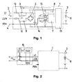
- Fig. 1 depicts a battery charging device comprising an alternating voltage input 2 and a direct voltage output 3, an input 4 for a protective conductor PEN as well as a rectifier 5 connected with the alternating voltage input 2.
- the alternating voltage input 2 is connected with two phases L1 and L2 or a phase L1 and a neutral conductor N
- the direct voltage output 3 is connected with a battery 6.
- the battery charging device 1 includes a voltage measuring unit 7 which is adapted to measure a voltage U 1 , U 2 derived from the voltage between the protective conductor PEN and at least one output voltage potential of the rectifier 5.
- a short-circuit may be detected between the respective output voltage potential and the ground or the protective conductor PEN.
- the voltage measuring unit 7, with the battery charging device 1 of Fig. 1 is adapted to measure voltages between the protective conductor PEN and both output voltage potentials of rectifier 5. In this manner, a short-circuit may be detected between both output voltage potentials of the rectifier 5 and ground, or the protective conductor PEN.
- the battery charging device 1 includes a switching device 9 connected to an evaluation circuit 8 and adapted to interrupt a current between the alternating voltage input 2 and the direct voltage output 3 if the fault signal indicates a fault (the voltage measuring unit 7 and the evaluation circuit 8 may, of course, also be implemented as a single component, for example a corresponding integrated circuit).
- the switching device 9 includes a relay with two switching contacts of which one, respectively, is assigned to the neutral conductor N or a phase L1, L2 of the alternating voltage input 3.
- the battery charging device 1 it would be feasible for the battery charging device 1 to comprise several separate switching devices 9 - for example relays - with a switching contact each, of which at least one, respectively, is assigned to the neutral conductor N or a phase L1, L2 of the alternating voltage input 3. This means that at least one switching device 9 is assigned to the neutral conductor N and at least one switching device 9 is assigned to a phase L1, L2 (see also Fig. 7 ).
- the switching device 9 is bridged by a series connection comprising a capacitor 10 and a current-limiting element, here a resistance 11. Furthermore, the battery charging device 1 includes a fuse 12 arranged in series with the switching device 9.
- the battery charging device 1 includes two voltage dividers 13 as well as buffer capacitor 14.
- the voltage dividers 13 are connected between the protective conductor PEN and one output voltage potential each of rectifier 5.
- the voltage measuring unit 7. The latter, for example, is used to keep the voltage in an intermediate circuit essentially constant. It may also be suitable to absorb the pulse currents of a connected consumer and to keep the associated electromagnetic interference away from the network. This is advantageous in cases as described here, where the battery charging device 1 includes a DC/DC converter, which, on the input side, is connected with an intermediate circuit supplied by the rectifier 5 and, on the output side, is connected with the direct voltage output 3.
- the switching device 9 the capacitor 10, the resistance 11, the fuse 12 and the voltage divider 13. It is, of course, also feasible for the components used in the example to be designed in an alternative manner. For example, instead of resistance 11, an active current limiter with a transistor may be provided. It is also feasible for the switching device 9 to comprise electronic switches (provided legal regulations do not make it mandatory to use galvanically isolating switches).
- Fig. 2 depicts a conventional fault current circuit breaker 16 in the supply line to the network. It is assumed that this trips only in case of pure fault alternating currents.
- the fault current circuit breaker 16 may be part of a domestic installation. But it is also feasible that the fault current circuit breaker 16, as is often the case, is integrated with the charging cable as a protection against electric shocks if no earth conductor is present.
- vehicle manufacturers tend to use very simple types which are guaranteed to react only to pure fault alternating currents (AC), not necessarily to pulsating direct currents (DC) such as they may well occur in modern charging devices.
- the positive output of rectifier 5, for a positive semi-wave of L1 is connected with this phase, at the same moment neutral conductor N, and thus the earth or protective conductor PEN, is connected with the negative output of rectifier 5.
- the voltage U 2 is therefore zero at this moment, whilst the voltage U 1 is a positive map of the positive semi-wave of L1.
- the negative output of rectifier 5, for a negative semi-wave of L1 is connected with this phase, at the same moment neutral conductor N, and thus the earth or protective conductor PEN, is connected with the positive output of rectifier 5.
- the voltage U 1 therefore is zero at this moment, whilst the voltage U 2 is a positive map of the negative semi-wave of L1.
- the voltage U 1 or U 2 is larger than zero only for one semi-wave of the mains frequency. Since the housing is earthed the voltages U 1 , U 2 remain unaffected, no matter whether the housing is touched by a person or not.
- the voltages U 1 or U 2 are of the same height compared to the potential of the protective conductor PEN which, of course, as mentioned in the beginning, has the same potential as the neutral conductor in the European network.
- the resulting progression for the voltages U 1 or U 2 is as shown in Fig. 4 .
- the potential of the protective conductor, in this network lies always between the two phase signals resulting in a symmetrical progression of the voltages U 1 or U 2 , but with half the amplitude for the same input voltage.
- the battery charging device 1 includes a closed metal housing which is connected with the protective conductor PEN.
- the protective conductor PEN in the European network is not connected, the potential of the housing or of the open protective conductor connection 4 is drawn by the voltage dividers 13 to half the output voltage of rectifier 5, resulting, as already shown in Fig. 4 , in a symmetrical progression for the two voltages U 1 or U 2 both for the European network and for the US-network.
- the dividing ratios of the voltage dividers 13 are essentially the same being 100:1 for example, so that the input voltage for the voltage measuring unit 7 is comparatively small. By choosing high resistance values the leakage current is also kept so small that it can neither harm any persons nor trip the fault current circuit breaker 16 upstream of the battery charging device 1.
- Fig. 3 European network
- Fig. 4 US-network
- Fig. 5 depicts a case where such a short-circuit occurs during a positive semi-wave (symbolised by a thunderbolt symbol at time t 1 ).
- Fig. 5 The anomaly occurring can be clearly recognized in Fig. 5 . Specifically voltage U 1 permanently remains at zero or slightly above zero, whereas voltage U 2 no longer exhibits any pauses between individual semi-waves. These anomalies in the time progression of voltage U 1 and/or U 2 may thus be utilised for detecting a contact with earth.
- the battery charging device 1 in this example is adapted to output the fault signal when at least one voltage of voltages U 1 or U 2 longer than the duration of a mains voltage semi-wave is zero or smaller than a specifiable value (in order to be able to also detect an earth contact with a higher resistance between the output voltage potential of rectifier 5 and earth).
- a specifiable value in order to be able to also detect an earth contact with a higher resistance between the output voltage potential of rectifier 5 and earth.
- the absence of a substantial value for a voltage U 1 or U 2 for longer than a semi-wave both in the European network and in the US-network is a sure indication that an earth contact has occurred.
- the battery charging device 1 could comprise an optical and/or acoustic output unit or be connected with the same so that with the aid thereof an optical and/or acoustic signal is output if an insulation defect is detected.
- a current may be interrupted with the aid of the switching device 9 via the alternating voltage input 2 if the fault signal indicates a defect.
- the switching device 9 in Fig. 5 is opened at time t 2 , so that the battery charging device 1 is now supplied via the RC elements formed by the capacitors 10 and the resistances 11. Voltage U 2 thus drops because of the additional voltage drop on the RC elements.
- the switching device 9 is operated during zero crossing.
- the time span during which voltage U 1 is equal to zero lasts longer than a semi-wave and at most two semi-waves. But it would also be feasible not to wait for a zero crossing and to immediately switch the switching device 9 off when voltage U 1 is of duration longer than a semi-wave or smaller than a specifiable value.
- the only fault current flowing is a fault alternating current which, different from a fault direct current, is recognised by the fault current circuit breaker 16 in the supply line. Thereafter the fault current circuit breaker 16 also switches off at time t 2 thereby achieving an even higher degree of safety.
- Fig. 6 depicts an analogue case to the case illustrated in Fig. 5 , however, the short-circuit is an earth contact occurring between the negative output voltage potential of rectifier 5 and earth or the metallic housing of the battery charging device 1 (time t 1 ).
- voltage U 2 is now longer than a zero semi-wave or smaller than a specifiable value leading again to a switch-off of switching device 9 (time t 2 ) or a tripping of the fault current circuit breaker 16 (time t 3 ).
- FIG. 7 schematically depicts a variant of the battery charging device with individual switching devices for the phases/the neutral conductor.
- the function of the arrangement of Fig. 7 is quite similar to the function of the arrangement of Fig. 1 .
- the battery charging device 1 includes a control which is adapted to keep the switching device 9 open when the battery charging device 1 is connected to an alternating current network L1, L2/N, at least during a trip time of a fault current circuit breaker 16 arranged upstream of the battery charging device 1 on the alternating-current side.
- Fig. 8 schematically depicts a variant of the battery charging device with a measuring unit 7 also measuring the alternate voltage of the phases L1, L2 / the neutral conductor N. If the evaluation circuit 8 detects an alternate input voltage, it concludes the battery charging device 1 has just been connected to an alternating current network L1, L2/N and keeps the switching device 9 open in the mentioned way.
- the battery charging device 1 is initially coupled only via the capacitors 10 to the alternating current network L1, L2/N which is why, if a short-circuit occurs between an output voltage potential of rectifier 5 and earth or the metallic housing of the battery charging device 1, only fault alternating currents can flow (see also the time period between t 2 and t 3 in figures 5 and 6 ).
- the fault current circuit breaker 16 in the supply line recognises this and therefore switches the voltage supply off. Since the switching device 9 is kept open for longer than the trip time of the fault current circuit breaker 16, there is in this case no voltage supply at all to the battery charging device 1 thus making it especially safe.
- this variant is an advantageous further development of the invention, the operation of this variant is not dependent upon measuring the voltage between the protective conductor PEN and at least one output voltage potential of rectifier 5.
- the variant shown may therefore also form the basis of an independent invention.
- control is not necessarily included in the measuring unit 7 and the evaluation circuit 8.
- control may also embodied as an individual device.
Landscapes
- Engineering & Computer Science (AREA)
- Power Engineering (AREA)
- Charge And Discharge Circuits For Batteries Or The Like (AREA)
Claims (13)
- Dispositif de charge de batterie (1), comprenant :- une entrée de tension alternative (2),- une sortie de tension continue (3),- une entrée (4) pour un conducteur de protection (PEN) et un redresseur (5) connecté à l'entrée de tension alternative (2),
caractérisé par
une unité de mesure de tension (7) adaptée pour mesurer la tension entre le conducteur de protection (PEN) et au moins un potentiel de tension de sortie du redresseur (5). - Dispositif de charge de batterie (1) selon la revendication 1, caractérisé par une unité de mesure de tension (7) adaptée pour mesurer les tensions (U1, U2) entre le conducteur de protection (PEN) et les deux potentiels de tension de sortie du redresseur (5).
- Dispositif de charge de batterie (1) selon la revendication 1 ou 2, caractérisé par un circuit d'évaluation (8) connecté à l'unité de mesure de tension (7) et adapté pour évaluer la progression dans le temps d'au moins une tension (U1, U2) mesurée et pour faire sortir un signal d'erreur en cas d'une anomalie, de préférence lorsqu'au moins une tension (U1, U2) est inférieure à une valeur pouvant être spécifiée plus longue qu'une demi-onde des tensions d'entrée du réseau.
- Dispositif de charge de batterie (1) selon la revendication 3, caractérisé par une unité de sortie optique et/ou acoustique qui est connectée au circuit d'évaluation (8) et est adaptée pour faire sortir un signal optique et/ou acoustique lorsque le signal d'erreur indique un défaut.
- Dispositif de charge de batterie (1) selon l'une des revendications 3 à 4, caractérisé par un dispositif de commutation (9) connecté au circuit d'évaluation (8) et adapté pour interrompre un courant via l'entrée de tension alternative (3) si le signal d'erreur indique un défaut.
- Dispositif de charge de batterie (1) selon la revendication 5, caractérisé par plusieurs dispositifs de commutation (9), l'un au moins d'entre eux étant respectivement affecté à un conducteur neutre (N) ou à une phase (L1, L2) de l'entrée de tension alternative (3).
- Dispositif de charge de batterie (1) selon la revendication 5 ou 6, caractérisé en ce qu'un dispositif de commutation (9) est ponté grâce à une connexion en série qui comprend un condensateur (10) et un élément limiteur de courant (11), un fusible (12) étant de préférence disposé en série avec le dispositif de commutation (9).
- Dispositif de charge de batterie (1) selon l'une des revendications 2 à 7, caractérisé par deux diviseurs de tension (13) lesquels, du côté d'entrée, sont disposés entre l'entrée (4) pour le conducteur de protection (PEN) et un potentiel de tension de sortie de chacun des redresseurs (5) et sont connectés, du côté de sortie, à l'unité de mesure de tension (7).
- Dispositif de charge de batterie (1) selon l'une des revendications 5 à 8, caractérisé par une commande qui est adaptée pour maintenir ouvert (s) le dispositif de commutation (9) ou des dispositifs de commutation lorsque le dispositif de charge de batterie (1) est connecté à un réseau de courant alternatif (L1, L2/N) au moins pendant un temps de trajet d'un disjoncteur de protection contre un courant de défaut (16) disposé en aval du dispositif de charge de batterie (1) du côté de la tension alternative.
- Dispositif de charge de batterie (1) selon l'une des revendications précédentes, caractérisé par un convertisseur CC/CC (15) lequel, du côté d'entrée, est connecté à un circuit intermédiaire alimenté par le redresseur (5) et est connecté, du côté de sortie, à la sortie de tension continue (3).
- Procédé pour faire fonctionner un dispositif de charge de batterie (1), lequel comprend une entrée de tension alternative (2) et une sortie de tension continue (3), une entrée pour un conducteur de protection (PEN) ainsi qu'un redresseur (5) connecté à l'entrée de tension alternative (2),
caractérisé en ce que la tension (U1, U2) est mesurée entre le conducteur de protection (PEN) et au moins un potentiel de tension de sortie du redresseur (5), de préférence entre le conducteur de protection et les deux sorties du redresseur. - Procédé tel que revendiqué dans la revendication 11, comprenant en outre les étapes suivantes :l'évaluation de la progression dans le temps d'au moins une tension mesurée ; etla sortie d'un signal d'erreur en réponse à une progression dans le temps anormale ; et comprenant en outre de préférence l'étape suivante :l'actionnement d'un commutateur pour interrompre l'alimentation d'entrée de courant alternatif sur la base de ladite étape de sortie d'un signal de défaut.
- Procédé tel que revendiqué par la revendication 12, comprenant en outre l'étape suivante :le pontage du commutateur grâce à une connexion ayant un condensateur et un limiteur de courant en série ; et comprenant en outre de préférence les étapes suivantes :la spécification d'une valeur minimale de cette au moins une tension mesurée ; etla sortie du signal d'erreur lorsque cette au moins une tension mesurée est inférieure à la valeur minimale spécifiée pour une durée plus longue qu'une demi-onde de tensions d'entrée du réseau et/oula sortie d'un signal sensoriel lorsque le signal d'erreur indique une anomalie.
Priority Applications (1)
| Application Number | Priority Date | Filing Date | Title |
|---|---|---|---|
| EP12722897.1A EP2707937B1 (fr) | 2011-05-10 | 2012-05-09 | Dispositif de charge de batterie et son procédé de fonctionnement |
Applications Claiming Priority (4)
| Application Number | Priority Date | Filing Date | Title |
|---|---|---|---|
| US201161484648P | 2011-05-10 | 2011-05-10 | |
| EP11165457A EP2523304A1 (fr) | 2011-05-10 | 2011-05-10 | Appareil de chargement de batterie et son procédé |
| PCT/IB2012/052303 WO2012153276A1 (fr) | 2011-05-10 | 2012-05-09 | Dispositif de charge de batterie et son procédé de fonctionnement |
| EP12722897.1A EP2707937B1 (fr) | 2011-05-10 | 2012-05-09 | Dispositif de charge de batterie et son procédé de fonctionnement |
Publications (2)
| Publication Number | Publication Date |
|---|---|
| EP2707937A1 EP2707937A1 (fr) | 2014-03-19 |
| EP2707937B1 true EP2707937B1 (fr) | 2015-07-29 |
Family
ID=44800909
Family Applications (2)
| Application Number | Title | Priority Date | Filing Date |
|---|---|---|---|
| EP11165457A Withdrawn EP2523304A1 (fr) | 2011-05-10 | 2011-05-10 | Appareil de chargement de batterie et son procédé |
| EP12722897.1A Not-in-force EP2707937B1 (fr) | 2011-05-10 | 2012-05-09 | Dispositif de charge de batterie et son procédé de fonctionnement |
Family Applications Before (1)
| Application Number | Title | Priority Date | Filing Date |
|---|---|---|---|
| EP11165457A Withdrawn EP2523304A1 (fr) | 2011-05-10 | 2011-05-10 | Appareil de chargement de batterie et son procédé |
Country Status (2)
| Country | Link |
|---|---|
| EP (2) | EP2523304A1 (fr) |
| WO (1) | WO2012153276A1 (fr) |
Cited By (1)
| Publication number | Priority date | Publication date | Assignee | Title |
|---|---|---|---|---|
| WO2021151623A1 (fr) * | 2020-01-31 | 2021-08-05 | Eaton Intelligent Power Limited | Dispositif et système de protection de circuit avec conversion et commande d'alimentation électrique pour charges cc |
Families Citing this family (1)
| Publication number | Priority date | Publication date | Assignee | Title |
|---|---|---|---|---|
| DE102017122220A1 (de) | 2017-09-26 | 2019-03-28 | Eaton Industries (Austria) Gmbh | Schutzschalter und Verfahren zum Betreiben eines Schutzschalters |
Family Cites Families (2)
| Publication number | Priority date | Publication date | Assignee | Title |
|---|---|---|---|---|
| IT1276444B1 (it) | 1995-06-27 | 1997-10-31 | Fiat Auto Spa | Dispositivo di controllo della messa a terra di un utilizzatore elettrico, in particolare della carrozzeria nei veicoli elettrici. |
| KR100460906B1 (ko) | 2002-09-13 | 2004-12-09 | 현대자동차주식회사 | 전기 차량용 충전 시스템 제어장치 |
-
2011
- 2011-05-10 EP EP11165457A patent/EP2523304A1/fr not_active Withdrawn
-
2012
- 2012-05-09 WO PCT/IB2012/052303 patent/WO2012153276A1/fr not_active Ceased
- 2012-05-09 EP EP12722897.1A patent/EP2707937B1/fr not_active Not-in-force
Cited By (2)
| Publication number | Priority date | Publication date | Assignee | Title |
|---|---|---|---|---|
| WO2021151623A1 (fr) * | 2020-01-31 | 2021-08-05 | Eaton Intelligent Power Limited | Dispositif et système de protection de circuit avec conversion et commande d'alimentation électrique pour charges cc |
| US12446133B2 (en) | 2020-01-31 | 2025-10-14 | Eaton Intelligent Power Limited | Circuit protection device and system with power supply conversion and control for DC loads |
Also Published As
| Publication number | Publication date |
|---|---|
| WO2012153276A1 (fr) | 2012-11-15 |
| EP2523304A1 (fr) | 2012-11-14 |
| EP2707937A1 (fr) | 2014-03-19 |
Similar Documents
| Publication | Publication Date | Title |
|---|---|---|
| EP2580829B1 (fr) | Protection de défaillance d'un disjoncteur haute tension à courant continu | |
| CN105934858B (zh) | 自动重合闸交流断路器 | |
| CN102576999B (zh) | 用于多相接地故障断续器的系统和方法 | |
| US9397494B2 (en) | Electrical monitoring device and method for safeguarding the protective function of a type A residual current device (RCD) | |
| CN100391072C (zh) | 监控中性线和地线的装置,以及包括该装置的电开关装置 | |
| US9219360B2 (en) | Safe quick disconnect leakage protector | |
| US10640000B2 (en) | Method and device for detecting a direct-current fault current | |
| US8705216B2 (en) | High sensitivity leakage current detection interrupter | |
| CN110691976B (zh) | 远供电源模块、直流电力系统和直流电力系统故障检测方法 | |
| CN103138327B (zh) | 电动汽车的充电装置、充电系统和运行保护开关的方法 | |
| CN101375478A (zh) | 包含响应第一跳闸电路提供重复信号故障的第二跳闸电路的电气开关设备 | |
| US20160025794A1 (en) | Apparatus and method for detecting leakage current | |
| JPH05501043A (ja) | 中性点もしくは接地喪失保護回路 | |
| CN104459367A (zh) | 电控和保护设备 | |
| EP3931928B1 (fr) | Commander une alimentation électrique d'un appareil | |
| JP2016537631A (ja) | 回路の電気的故障を検出する方法 | |
| EP4060847B1 (fr) | Procédé et appareil de surveillance et de protection contre les décharges électriques pour une extrémité d'utilisateur basse tension | |
| CN102324717A (zh) | 一种漏电保护装置 | |
| JP2023504681A (ja) | 残留電流回路遮断器 | |
| EP2707937B1 (fr) | Dispositif de charge de batterie et son procédé de fonctionnement | |
| US20240404766A1 (en) | Circuit breaker and method | |
| JP5137242B2 (ja) | 回路遮断器 | |
| EP1252696B1 (fr) | Dispositif electronique a courant de fuite a la terre ameliore | |
| CN119790556A (zh) | 保护开关设备及方法 | |
| KR200440531Y1 (ko) | 누전 차단기 |
Legal Events
| Date | Code | Title | Description |
|---|---|---|---|
| PUAI | Public reference made under article 153(3) epc to a published international application that has entered the european phase |
Free format text: ORIGINAL CODE: 0009012 |
|
| 17P | Request for examination filed |
Effective date: 20131210 |
|
| AK | Designated contracting states |
Kind code of ref document: A1 Designated state(s): AL AT BE BG CH CY CZ DE DK EE ES FI FR GB GR HR HU IE IS IT LI LT LU LV MC MK MT NL NO PL PT RO RS SE SI SK SM TR |
|
| DAX | Request for extension of the european patent (deleted) | ||
| GRAP | Despatch of communication of intention to grant a patent |
Free format text: ORIGINAL CODE: EPIDOSNIGR1 |
|
| INTG | Intention to grant announced |
Effective date: 20150302 |
|
| GRAS | Grant fee paid |
Free format text: ORIGINAL CODE: EPIDOSNIGR3 |
|
| GRAA | (expected) grant |
Free format text: ORIGINAL CODE: 0009210 |
|
| AK | Designated contracting states |
Kind code of ref document: B1 Designated state(s): AL AT BE BG CH CY CZ DE DK EE ES FI FR GB GR HR HU IE IS IT LI LT LU LV MC MK MT NL NO PL PT RO RS SE SI SK SM TR |
|
| REG | Reference to a national code |
Ref country code: GB Ref legal event code: FG4D |
|
| REG | Reference to a national code |
Ref country code: CH Ref legal event code: EP |
|
| REG | Reference to a national code |
Ref country code: AT Ref legal event code: REF Ref document number: 739954 Country of ref document: AT Kind code of ref document: T Effective date: 20150815 |
|
| REG | Reference to a national code |
Ref country code: IE Ref legal event code: FG4D |
|
| REG | Reference to a national code |
Ref country code: DE Ref legal event code: R096 Ref document number: 602012009156 Country of ref document: DE |
|
| REG | Reference to a national code |
Ref country code: AT Ref legal event code: MK05 Ref document number: 739954 Country of ref document: AT Kind code of ref document: T Effective date: 20150729 |
|
| REG | Reference to a national code |
Ref country code: LT Ref legal event code: MG4D |
|
| REG | Reference to a national code |
Ref country code: NL Ref legal event code: MP Effective date: 20150729 |
|
| PG25 | Lapsed in a contracting state [announced via postgrant information from national office to epo] |
Ref country code: NO Free format text: LAPSE BECAUSE OF FAILURE TO SUBMIT A TRANSLATION OF THE DESCRIPTION OR TO PAY THE FEE WITHIN THE PRESCRIBED TIME-LIMIT Effective date: 20151029 Ref country code: GR Free format text: LAPSE BECAUSE OF FAILURE TO SUBMIT A TRANSLATION OF THE DESCRIPTION OR TO PAY THE FEE WITHIN THE PRESCRIBED TIME-LIMIT Effective date: 20151030 Ref country code: FI Free format text: LAPSE BECAUSE OF FAILURE TO SUBMIT A TRANSLATION OF THE DESCRIPTION OR TO PAY THE FEE WITHIN THE PRESCRIBED TIME-LIMIT Effective date: 20150729 Ref country code: LV Free format text: LAPSE BECAUSE OF FAILURE TO SUBMIT A TRANSLATION OF THE DESCRIPTION OR TO PAY THE FEE WITHIN THE PRESCRIBED TIME-LIMIT Effective date: 20150729 Ref country code: LT Free format text: LAPSE BECAUSE OF FAILURE TO SUBMIT A TRANSLATION OF THE DESCRIPTION OR TO PAY THE FEE WITHIN THE PRESCRIBED TIME-LIMIT Effective date: 20150729 |
|
| PG25 | Lapsed in a contracting state [announced via postgrant information from national office to epo] |
Ref country code: SE Free format text: LAPSE BECAUSE OF FAILURE TO SUBMIT A TRANSLATION OF THE DESCRIPTION OR TO PAY THE FEE WITHIN THE PRESCRIBED TIME-LIMIT Effective date: 20150729 Ref country code: PL Free format text: LAPSE BECAUSE OF FAILURE TO SUBMIT A TRANSLATION OF THE DESCRIPTION OR TO PAY THE FEE WITHIN THE PRESCRIBED TIME-LIMIT Effective date: 20150729 Ref country code: ES Free format text: LAPSE BECAUSE OF FAILURE TO SUBMIT A TRANSLATION OF THE DESCRIPTION OR TO PAY THE FEE WITHIN THE PRESCRIBED TIME-LIMIT Effective date: 20150729 Ref country code: RS Free format text: LAPSE BECAUSE OF FAILURE TO SUBMIT A TRANSLATION OF THE DESCRIPTION OR TO PAY THE FEE WITHIN THE PRESCRIBED TIME-LIMIT Effective date: 20150729 Ref country code: IS Free format text: LAPSE BECAUSE OF FAILURE TO SUBMIT A TRANSLATION OF THE DESCRIPTION OR TO PAY THE FEE WITHIN THE PRESCRIBED TIME-LIMIT Effective date: 20151129 Ref country code: AT Free format text: LAPSE BECAUSE OF FAILURE TO SUBMIT A TRANSLATION OF THE DESCRIPTION OR TO PAY THE FEE WITHIN THE PRESCRIBED TIME-LIMIT Effective date: 20150729 Ref country code: PT Free format text: LAPSE BECAUSE OF FAILURE TO SUBMIT A TRANSLATION OF THE DESCRIPTION OR TO PAY THE FEE WITHIN THE PRESCRIBED TIME-LIMIT Effective date: 20151130 Ref country code: HR Free format text: LAPSE BECAUSE OF FAILURE TO SUBMIT A TRANSLATION OF THE DESCRIPTION OR TO PAY THE FEE WITHIN THE PRESCRIBED TIME-LIMIT Effective date: 20150729 |
|
| PG25 | Lapsed in a contracting state [announced via postgrant information from national office to epo] |
Ref country code: NL Free format text: LAPSE BECAUSE OF FAILURE TO SUBMIT A TRANSLATION OF THE DESCRIPTION OR TO PAY THE FEE WITHIN THE PRESCRIBED TIME-LIMIT Effective date: 20150729 |
|
| PG25 | Lapsed in a contracting state [announced via postgrant information from national office to epo] |
Ref country code: EE Free format text: LAPSE BECAUSE OF FAILURE TO SUBMIT A TRANSLATION OF THE DESCRIPTION OR TO PAY THE FEE WITHIN THE PRESCRIBED TIME-LIMIT Effective date: 20150729 Ref country code: SK Free format text: LAPSE BECAUSE OF FAILURE TO SUBMIT A TRANSLATION OF THE DESCRIPTION OR TO PAY THE FEE WITHIN THE PRESCRIBED TIME-LIMIT Effective date: 20150729 Ref country code: CZ Free format text: LAPSE BECAUSE OF FAILURE TO SUBMIT A TRANSLATION OF THE DESCRIPTION OR TO PAY THE FEE WITHIN THE PRESCRIBED TIME-LIMIT Effective date: 20150729 Ref country code: DK Free format text: LAPSE BECAUSE OF FAILURE TO SUBMIT A TRANSLATION OF THE DESCRIPTION OR TO PAY THE FEE WITHIN THE PRESCRIBED TIME-LIMIT Effective date: 20150729 Ref country code: IT Free format text: LAPSE BECAUSE OF FAILURE TO SUBMIT A TRANSLATION OF THE DESCRIPTION OR TO PAY THE FEE WITHIN THE PRESCRIBED TIME-LIMIT Effective date: 20150729 |
|
| REG | Reference to a national code |
Ref country code: DE Ref legal event code: R097 Ref document number: 602012009156 Country of ref document: DE |
|
| PG25 | Lapsed in a contracting state [announced via postgrant information from national office to epo] |
Ref country code: RO Free format text: LAPSE BECAUSE OF FAILURE TO SUBMIT A TRANSLATION OF THE DESCRIPTION OR TO PAY THE FEE WITHIN THE PRESCRIBED TIME-LIMIT Effective date: 20150729 |
|
| PLBE | No opposition filed within time limit |
Free format text: ORIGINAL CODE: 0009261 |
|
| STAA | Information on the status of an ep patent application or granted ep patent |
Free format text: STATUS: NO OPPOSITION FILED WITHIN TIME LIMIT |
|
| 26N | No opposition filed |
Effective date: 20160502 |
|
| PG25 | Lapsed in a contracting state [announced via postgrant information from national office to epo] |
Ref country code: BE Free format text: LAPSE BECAUSE OF NON-PAYMENT OF DUE FEES Effective date: 20160531 Ref country code: SI Free format text: LAPSE BECAUSE OF FAILURE TO SUBMIT A TRANSLATION OF THE DESCRIPTION OR TO PAY THE FEE WITHIN THE PRESCRIBED TIME-LIMIT Effective date: 20150729 |
|
| PG25 | Lapsed in a contracting state [announced via postgrant information from national office to epo] |
Ref country code: BE Free format text: LAPSE BECAUSE OF FAILURE TO SUBMIT A TRANSLATION OF THE DESCRIPTION OR TO PAY THE FEE WITHIN THE PRESCRIBED TIME-LIMIT Effective date: 20150729 Ref country code: LU Free format text: LAPSE BECAUSE OF FAILURE TO SUBMIT A TRANSLATION OF THE DESCRIPTION OR TO PAY THE FEE WITHIN THE PRESCRIBED TIME-LIMIT Effective date: 20160509 |
|
| REG | Reference to a national code |
Ref country code: CH Ref legal event code: PL |
|
| GBPC | Gb: european patent ceased through non-payment of renewal fee |
Effective date: 20160509 |
|
| PG25 | Lapsed in a contracting state [announced via postgrant information from national office to epo] |
Ref country code: LI Free format text: LAPSE BECAUSE OF NON-PAYMENT OF DUE FEES Effective date: 20160531 Ref country code: CH Free format text: LAPSE BECAUSE OF NON-PAYMENT OF DUE FEES Effective date: 20160531 |
|
| REG | Reference to a national code |
Ref country code: IE Ref legal event code: MM4A |
|
| REG | Reference to a national code |
Ref country code: FR Ref legal event code: ST Effective date: 20170131 |
|
| PG25 | Lapsed in a contracting state [announced via postgrant information from national office to epo] |
Ref country code: FR Free format text: LAPSE BECAUSE OF NON-PAYMENT OF DUE FEES Effective date: 20160531 |
|
| PG25 | Lapsed in a contracting state [announced via postgrant information from national office to epo] |
Ref country code: GB Free format text: LAPSE BECAUSE OF NON-PAYMENT OF DUE FEES Effective date: 20160509 Ref country code: IE Free format text: LAPSE BECAUSE OF NON-PAYMENT OF DUE FEES Effective date: 20160509 |
|
| REG | Reference to a national code |
Ref country code: DE Ref legal event code: R082 Ref document number: 602012009156 Country of ref document: DE Representative=s name: ROESLER-RASCH-VAN DER HEIDE & PARTNER PATENT- , DE Ref country code: DE Ref legal event code: R082 Ref document number: 602012009156 Country of ref document: DE Representative=s name: ROESLER - RASCH - VAN DER HEIDE & PARTNER PATE, DE |
|
| PG25 | Lapsed in a contracting state [announced via postgrant information from national office to epo] |
Ref country code: HU Free format text: LAPSE BECAUSE OF FAILURE TO SUBMIT A TRANSLATION OF THE DESCRIPTION OR TO PAY THE FEE WITHIN THE PRESCRIBED TIME-LIMIT; INVALID AB INITIO Effective date: 20120509 Ref country code: SM Free format text: LAPSE BECAUSE OF FAILURE TO SUBMIT A TRANSLATION OF THE DESCRIPTION OR TO PAY THE FEE WITHIN THE PRESCRIBED TIME-LIMIT Effective date: 20150729 Ref country code: CY Free format text: LAPSE BECAUSE OF FAILURE TO SUBMIT A TRANSLATION OF THE DESCRIPTION OR TO PAY THE FEE WITHIN THE PRESCRIBED TIME-LIMIT Effective date: 20150729 |
|
| PG25 | Lapsed in a contracting state [announced via postgrant information from national office to epo] |
Ref country code: MK Free format text: LAPSE BECAUSE OF FAILURE TO SUBMIT A TRANSLATION OF THE DESCRIPTION OR TO PAY THE FEE WITHIN THE PRESCRIBED TIME-LIMIT Effective date: 20150729 Ref country code: TR Free format text: LAPSE BECAUSE OF FAILURE TO SUBMIT A TRANSLATION OF THE DESCRIPTION OR TO PAY THE FEE WITHIN THE PRESCRIBED TIME-LIMIT Effective date: 20150729 Ref country code: MT Free format text: LAPSE BECAUSE OF NON-PAYMENT OF DUE FEES Effective date: 20160531 Ref country code: MC Free format text: LAPSE BECAUSE OF FAILURE TO SUBMIT A TRANSLATION OF THE DESCRIPTION OR TO PAY THE FEE WITHIN THE PRESCRIBED TIME-LIMIT Effective date: 20150729 |
|
| PG25 | Lapsed in a contracting state [announced via postgrant information from national office to epo] |
Ref country code: BG Free format text: LAPSE BECAUSE OF FAILURE TO SUBMIT A TRANSLATION OF THE DESCRIPTION OR TO PAY THE FEE WITHIN THE PRESCRIBED TIME-LIMIT Effective date: 20150729 |
|
| PG25 | Lapsed in a contracting state [announced via postgrant information from national office to epo] |
Ref country code: AL Free format text: LAPSE BECAUSE OF FAILURE TO SUBMIT A TRANSLATION OF THE DESCRIPTION OR TO PAY THE FEE WITHIN THE PRESCRIBED TIME-LIMIT Effective date: 20150729 |
|
| REG | Reference to a national code |
Ref country code: DE Ref legal event code: R081 Ref document number: 602012009156 Country of ref document: DE Owner name: BRUSA HYPOWER AG, CH Free format text: FORMER OWNER: BRUSA ELEKTRONIK AG, SENNWALD, CH |
|
| PGFP | Annual fee paid to national office [announced via postgrant information from national office to epo] |
Ref country code: DE Payment date: 20220722 Year of fee payment: 11 |
|
| REG | Reference to a national code |
Ref country code: DE Ref legal event code: R119 Ref document number: 602012009156 Country of ref document: DE |
|
| PG25 | Lapsed in a contracting state [announced via postgrant information from national office to epo] |
Ref country code: DE Free format text: LAPSE BECAUSE OF NON-PAYMENT OF DUE FEES Effective date: 20231201 |