EP2708689B1 - Kabelverbindungsstruktur für ein bewegliches bauteil - Google Patents
Kabelverbindungsstruktur für ein bewegliches bauteil Download PDFInfo
- Publication number
- EP2708689B1 EP2708689B1 EP12783020.6A EP12783020A EP2708689B1 EP 2708689 B1 EP2708689 B1 EP 2708689B1 EP 12783020 A EP12783020 A EP 12783020A EP 2708689 B1 EP2708689 B1 EP 2708689B1
- Authority
- EP
- European Patent Office
- Prior art keywords
- cable
- wing pieces
- movable member
- inner wire
- passing part
- Prior art date
- Legal status (The legal status is an assumption and is not a legal conclusion. Google has not performed a legal analysis and makes no representation as to the accuracy of the status listed.)
- Active
Links
Images



Classifications
-
- F—MECHANICAL ENGINEERING; LIGHTING; HEATING; WEAPONS; BLASTING
- F16—ENGINEERING ELEMENTS AND UNITS; GENERAL MEASURES FOR PRODUCING AND MAINTAINING EFFECTIVE FUNCTIONING OF MACHINES OR INSTALLATIONS; THERMAL INSULATION IN GENERAL
- F16C—SHAFTS; FLEXIBLE SHAFTS; ELEMENTS OR CRANKSHAFT MECHANISMS; ROTARY BODIES OTHER THAN GEARING ELEMENTS; BEARINGS
- F16C1/00—Flexible shafts; Mechanical means for transmitting movement in a flexible sheathing
- F16C1/10—Means for transmitting linear movement in a flexible sheathing, e.g. "Bowden-mechanisms"
- F16C1/12—Arrangements for transmitting movement to or from the flexible member
- F16C1/14—Construction of the end-piece of the flexible member; Attachment thereof to the flexible member
-
- E—FIXED CONSTRUCTIONS
- E05—LOCKS; KEYS; WINDOW OR DOOR FITTINGS; SAFES
- E05B—LOCKS; ACCESSORIES THEREFOR; HANDCUFFS
- E05B79/00—Mounting or connecting vehicle locks or parts thereof
- E05B79/02—Mounting of vehicle locks or parts thereof
- E05B79/06—Mounting of handles, e.g. to the wing or to the lock
-
- E—FIXED CONSTRUCTIONS
- E05—LOCKS; KEYS; WINDOW OR DOOR FITTINGS; SAFES
- E05B—LOCKS; ACCESSORIES THEREFOR; HANDCUFFS
- E05B79/00—Mounting or connecting vehicle locks or parts thereof
- E05B79/10—Connections between movable lock parts
- E05B79/20—Connections between movable lock parts using flexible connections, e.g. Bowden cables
-
- E—FIXED CONSTRUCTIONS
- E05—LOCKS; KEYS; WINDOW OR DOOR FITTINGS; SAFES
- E05B—LOCKS; ACCESSORIES THEREFOR; HANDCUFFS
- E05B85/00—Details of vehicle locks not provided for in groups E05B77/00 - E05B83/00
- E05B85/10—Handles
- E05B85/14—Handles pivoted about an axis parallel to the wing
- E05B85/16—Handles pivoted about an axis parallel to the wing a longitudinal grip part being pivoted at one end about an axis perpendicular to the longitudinal axis of the grip part
-
- F—MECHANICAL ENGINEERING; LIGHTING; HEATING; WEAPONS; BLASTING
- F16—ENGINEERING ELEMENTS AND UNITS; GENERAL MEASURES FOR PRODUCING AND MAINTAINING EFFECTIVE FUNCTIONING OF MACHINES OR INSTALLATIONS; THERMAL INSULATION IN GENERAL
- F16G—BELTS, CABLES, OR ROPES, PREDOMINANTLY USED FOR DRIVING PURPOSES; CHAINS; FITTINGS PREDOMINANTLY USED THEREFOR
- F16G11/00—Means for fastening cables or ropes to one another or to other objects; Caps or sleeves for fixing on cables or ropes
- F16G11/08—Fastenings for securing ends of driving-cables to one another, the fastenings having approximately the same diameter as the cables
- F16G11/09—Fastenings for securing ends of driving-cables to one another, the fastenings having approximately the same diameter as the cables incorporating hinge joints or pivots for the attachment of the cable ends
-
- Y—GENERAL TAGGING OF NEW TECHNOLOGICAL DEVELOPMENTS; GENERAL TAGGING OF CROSS-SECTIONAL TECHNOLOGIES SPANNING OVER SEVERAL SECTIONS OF THE IPC; TECHNICAL SUBJECTS COVERED BY FORMER USPC CROSS-REFERENCE ART COLLECTIONS [XRACs] AND DIGESTS
- Y10—TECHNICAL SUBJECTS COVERED BY FORMER USPC
- Y10T—TECHNICAL SUBJECTS COVERED BY FORMER US CLASSIFICATION
- Y10T74/00—Machine element or mechanism
- Y10T74/20—Control lever and linkage systems
- Y10T74/20396—Hand operated
- Y10T74/20402—Flexible transmitter [e.g., Bowden cable]
- Y10T74/20462—Specific cable connector or guide
Definitions
- the present invention relates to a cable connection structure to a movable member.
- Patent Document 1 discloses a door handle device for a vehicle using a cable device as an operating force transmission means.
- a door handle movable member
- a locking part to which a cable end formed at a tip of the inner cable is locked.
- the mounting of the cable tip is made by passing a cable end and the inner wire through an end fitting part opened toward the surface and a slit extending from a peripheral edge of the end fitting part to a material end and communicating to a notch and then rotating the cable device around the locking part.
- the inner wire In a mounted state, the inner wire is inserted through an interior of a notch and therefore a movement thereof toward the surface is restricted. As a result, the detachment of the inner wire from the movable member is prevented.
- the locking part transmits an operating force in a drawing direction from an outer casing to the inner cable when the movable member is operated to rotate and the inner cable is returned to its original position by a tensile force loaded by an operated-side member when the movable member is returned to its initial rotational position.
- Patent Document 1 JP-A- 06-212846
- Embodiments of the present invention relate to a cable connection structure to a movable member and a door handle device for a vehicle incorporating the connection structure, which are capable of securely preventing the detachment of the inner cable from the movable member.
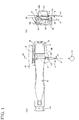
- a door handle device of a vehicle is formed in such a way that an operation handle 16 is rotatably connected to one end of a handle base 15 disposed along a rear surface of a door panel 14.
- the handle device is mounted in a posture where a left side thereof in section (a) of Fig. 1 is directed toward the front of a vehicle.
- a longitudinal direction of a vehicle is referred to as "a front and rear”.
- the operation handle 16 includes a hinge leg 16a on a front end thereof and an operation leg 16b on a rear end thereof. As shown in Fig. 3 , the hinge leg 16a is inserted into a door body through a front mounting opening 14a opened in the door panel 14, the operation leg 16b is inserted into the door body through a rear mounting opening 14b of the door panel 14 and then the whole operation handle 16 is mounted while being slid forward. A gasket 17 is interposed between the operation handle 16 and the surface of the door panel 14 so as to surround the mounting opening 14a, 14b.
- a front opening 15a for accommodating the hinge leg 16a of the operation handle 16 is provided and a rear opening 15b for accommodating the operation leg 16b of the operation handle 16 are provided so as to correspond to the rear mounting opening 14b.
- a lever (movable member 6) is rotatably connected to the handle base 15 by a pivot 6a that is long in a front-rear direction and the lever 6 is urged toward an initial rotation position by a torsion spring 18 that is mounted in a state of being wound around the pivot 6a.
- the lever includes an actuation arm 6b that is long in a direction perpendicular to the pivot 6a. In the initial rotation position, the lever directly faces a front end surface of a lower end of the inserted operation leg 16b.
- the lever 6 When the operation handle 16 is slid forward in a state where the hinge leg 16a and the operation leg 16b are inserted into the front and rear openings 15a, 15b, the lever 6 having received a component force from a contact portion between the front end surface of the lower end of the operation leg 16b and a rear end surface of the actuation arm 6b is rotated in an actuation direction (a direction in which a deflection angle of the torsion spring 18 is increased) against an urging force of the torsion spring 18 and locked to a locking end 16c of the operation leg 16b. Then, the lever applies, to the operation handle 16, an urging force in a direction of the initial rotation position shown in section (a) of Fig. 2 .
- the front end of the hinge leg 16a and the front opening 15a of the handle base 15 are in a sliding contact state through an arc-shaped sliding contact surface (not shown) at a suitable location.
- the operation handle 16 can be operated to rotate around a pseudo rotation center by raising a rear end thereof.
- the handle base 15 is finally fixed to the door panel 14 using a fixing portion 15c and a fixing member 19 mounted to the rear opening 15b.
- the fixing member 19 restricts the rearward movement of the operation handle 16 and therefore the detachment of the operation handle 16 is prevented.
- a counterweight 20 is mounted to the handle base 15 in coaxial with the lever 6 and cancels an inertia force generated in the operation handle 16 when a side collision force is applied to a vehicle, so that an inadvertent door opening operation of the operation handle 16 is prevented.
- a cable device 5 is connected to the lever 6.
- the cable device 5 is a so-called pull-use cable device that is actuated by loading a tensile force to an inner wire 1.
- the cable device 5 includes an inner cable 3 configured by fixing a spherical cable end 2 to a leading end of the inner wire 1 and an outer casing 4 through which the inner wire 1 of the inner cable 3 can be freely inserted during movement.
- the cable device is retained in a predetermined position by locking a fixture 4a formed in a leading end of the outer casing 4 to a cable locking portion 15d formed in the handle base 15 (see section (a) of Fig. 1 and section (b) of Fig. 1 ).
- a bale shape, a rod shape or the like can be suitably used as the shape of the cable end 2.
- a pair of wing pieces 7 is provided at positions suitably spaced away from the insertion position of the pivot 6a of the lever 6. These wing pieces 7 are provided to face each other at an interval that allows passage of the inner wire 1 but does not allow passage of the cable end 2, thereby forming an inner wire insertion area 12.
- a cable introduction opening 8 communicating with the inner wire insertion area 12 is opened at one of the wing pieces 7.
- the cable introduction opening 8 includes a cable end passing part 9 through which the cable end 2 of the inner cable 3 can be inserted and a wire passing part 13 reaching an end edge of the wing piece 7 in a straight line form with a side edge of the cable end passing part 9 being as a base end.
- the cable end passing part 9 has an elliptical shape in which one half-circle of a circular hole for allowing passage of the cable end 2 is spaced from the other half-circle.
- an end fitting part 10 having a bottom end is formed at an opposite location (see section (a) of Fig. 4 to Fig. 5 ).
- the end fitting part 10 has the same form as the cable end passing part 9 and is adjacent to a die cutting hole 10'.
- a projecting piece-like cover 11 is provided at an extending portion 9a including the one half-circle of the cable end passing part 9.
- the cover 11 is formed in a range where the cable end 2 can pass through the area other than the cover and the cable end 2 can be detached from the cable end passing part 9 when the cable end 2 is moved to a termination of the extending portion 9a.
- a termination wall surface defined by the wire passing part 13 is further extended in the rear direction and therefore a culvert-shaped extending portion 12' sandwiched between the wing pieces 7 is formed.
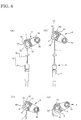
- connection of the inner cable 3 to the lever 6 configured described above is made by, first, passing the cable end 2 through the cable end passing part 9 in a state where the inner wire 1 directly faces the wire passing part 13, as shown in section (b) of Fig. 4 and section (c) of Fig. 4 , introducing the inner wire 1 between the wing pieces 7, i.e., to the inner wire insertion area 12 and then rotating the whole cable device 5 about the cable end 2, as shown in section (d) of Fig. 4 .
- the inner wire 1 By rotating the inner wire 1 from the mounted operating position, the inner wire 1 is deviated from the wire passing part 13 and thus moved to the culvert-shaped portion having both sides held between the wing pieces 7, thereby restricting the detachment of the inner wire from the inner wire insertion area 12.
- the opposite areas of the cable end 2 are fitted between the cable end passing part 9 and the end fitting part 10 and therefore the movement of the cable end 2 to the wire passing part 13 is restricted. In this manner, there is no case that the inner wire is detached from the lever 6.
- the cable connection structure for connecting the substantially spherical cable end 2 provided at a leading end of the inner wire 1 to the movable member 6 is provided.
- the movable member 6 may include a pair of wing pieces 7 for holding the inner wire 1, the cable introduction opening 8 for guiding the cable end 2 between the wing pieces 7 and the substantially elliptical cable end passing part 9 for supporting the cable end 2 in a displaceable manner.
- a long axis of the cable end passing part 9 may substantially coincide with a cable introduction direction.
- the cable connection structure to the movable member is provided for connecting, to the movable member 6, the cable device 5 in which the inner cable 3 configured by fixing the cable end 2 to a leading end of the inner wire 1 is slidably inserted into the outer casing 4.
- the movable member 6 is provided with a pair of wing pieces 7 facing each other in an interval allowing the insertion of the inner wire 1.
- the cable introduction opening 8 for guiding the leading end of the inner cable 3 between the wing pieces 7 is opened at one of the wing pieces 7.
- the end fitting part 10 for locking the cable end 2 introduced between the wing pieces 7 in cooperation with the cable end passing part 9 of the cable introduction opening 8 is provided at the other of the wing pieces 7.
- the cable end passing part 9 and the end fitting part 10 may be configured to extend to a position where the movement of the cable end 2 in an opposite direction with respect to a contact edge to the cable end 2 during operation of the inner cable 3 is allowed and the inner wire 1 rotated around the cable end 2 in a longitudinal end does not overlap with the entire length of the cable introduction opening 8.
- connection of the cable device 5 to the movable member 6 is made, as shown in Fig. 4 , by passing a leading end of the inner cable 3, i.e., the cable end 2 and a leading end of the inner wire 1 located at a base end of the cable end 2 through the cable introduction opening 8 to locate the inner wire 1 between the wing pieces 7 and then rotating the entire cable device 5 around the cable end 2.
- opposite ends of the end cable are fitted into the cable end passing part 9 of the cable introduction opening 8 and the end fitting part 10 facing the cable end passing part and therefore the movable member 6 and the inner cable 3 are connected to each other.
- the inner wire 1 is fitted between the wing pieces 7 and therefore the movement of the inner wire in an opening direction of the cable introduction opening 8 is restricted. With this configuration, the detachment of the inner cable 3 from the movable member 6 is prevented.
- the cable end 2 and the end fitting part 10 are considered as a rotatable pin support point. Further, even in this example where the inner cable 3 itself has proper rigidity, distortion in a rotation direction of the inner cable 3 rotating about the cable end 2 occurs in an initial state where the rotation of the cable end 2 is allowed. Thereafter, the buckling distortion proceeds in a state where the side walls of the extending portions 9a, 10a and the inner cable 3 are in contact with each other.
- the extending portions 9a, 10a extend to a position where the inner wire 1 rotated around the cable end 2 in a longitudinal end does not overlap with the entire length of the cable introduction opening 8, there is no case that the inner wire 1 directly faces over the entire length of the wire passing part 13 in the procedure of the buckling distortion. Therefore, the inner wire 1 is still maintained in a state of being fitted between the wing pieces 7 even after occurrence of the buckling, so that the detachment of the inner cable 3 from the movable member 6 is securely prevented.
- the extending portion 9a of the cable end passing part 9 may be covered with the cover 11. According to this structure, it is possible to completely prevent the detachment of the cable end 2 from the extending portions 9a, 10a.
- the cable connection structure to the movable member is provided for connecting, to the movable member 6, the cable device 5 in which the inner cable 3 configured by fixing the cable end 2 to a leading end of the inner wire 1 is slidably inserted into the outer casing 4.
- the movable member 6 is provided with a pair of wing pieces 7 facing each other in an interval allowing the insertion of the inner wire 1.
- the cable introduction opening 8 for guiding the leading end of the inner cable 3 between the wing pieces 7 is opened at one of the wing pieces 7.
- the end fitting part 10 for locking the cable end 2 introduced between the wing pieces 7 in cooperation with the cable end passing part 9 of the cable introduction opening 8 is provided at the other of the wing pieces 7.
- the inner wire insertion area 12 between the wing pieces 7 may be configured to extend beyond a longitudinal end edge defined by the wire passing part 12 of the cable introduction opening 8.
- the inner wire 1 proceeds via a position where the inner wire directly faces the wire passing part 13 in the procedure of the buckling distortion, the inner wire is immediately pressed against the extending portion 12' without staying at that position and an operation force to the movable member 6 serves as a force to press the inner wire 1 against the innermost wall of the extending portion 12'. Therefore, the detachment of the inner cable 3 from the movable member 6 is securely prevented.
- the cable connection structure to the movable member is provided for connecting, to the movable member 6, the cable device 5 in which the inner cable 3 configured by fixing the cable end 2 to a leading end of the inner wire 1 is slidably inserted into the outer casing 4.
- the movable member 6 is provided with a pair of wing pieces 7 facing each other in an interval allowing the insertion of the inner wire 1.
- the cable introduction opening 8 for guiding the leading end of the inner cable 3 between the wing pieces 7 is opened at one of the wing pieces 7.
- the end fitting part 10 for locking the cable end 2 introduced between the wing pieces 7 in cooperation with the cable end passing part 9 of the cable introduction opening 8 is provided at the other of the wing pieces 7.
- the cable end passing part 9 and the end fitting part 10 may extend in an opposite direction with respect to a contact edge to the cable end 2 during operation of the inner cable 3 and the inner wire insertion area between the wing pieces 7 may be configured to extend beyond a longitudinal end edge defined by the wire passing part 12.
- the cable end 2 is moved to the extending portions 9a, 10a of the cable end passing part 9 and the end fitting part 10 and then subjected to the buckling distortion. Since the load point of the buckling load is displaced to an end of the extending portions 9a, 10a, there is little case that the inner wire directly faces the wire passing part 13 in the procedure of the rotation buckling distortion of the inner wire, and the inner wire stays at the extending portion 12' of the wire passing part 13. Therefore, the detachment of the inner cable 3 from the movable member 6 is securely prevented.
Landscapes
- Engineering & Computer Science (AREA)
- General Engineering & Computer Science (AREA)
- Mechanical Engineering (AREA)
- Health & Medical Sciences (AREA)
- Oral & Maxillofacial Surgery (AREA)
- Lock And Its Accessories (AREA)
- Joints Allowing Movement (AREA)
Claims (10)
- Kabelverbindungsstruktur zu einem beweglichen Element (6) zum Verbinden eines Kabelendes (2), das an einem Vorderende eines Innendrahts (1) vorgesehen ist, mit dem beweglichen Element (6),
dadurch gekennzeichnet, dass das bewegliche Element (6) aufweist:ein Paar von Flügelstücken (7), die den Innendraht (1) halten;eine Kabeleinführöffnung (8) zum Führen des Kabelendes (2) zwischen die Flügelstücke (7), undein im Wesentlichen elliptisches Kabelenddurchgangsteil (9), das das Kabelende (2) verlagerbar trägt,wobei eine Längsachse des im Wesentlichen elliptischen Kabelenddurchgangsteils (9) mit einer Kabeleinführrichtung im Wesentlichen übereinstimmt. - Die Kabelverbindungsstruktur zu dem beweglichen Element (6) nach Anspruch 1,
wobei die Kabeleinführöffnung (8) zum Führen eines Vorderendes eines aus dem Innendraht (1) und dem Kabelende (2) konfigurierten Innenkabels (3) zwischen die Flügelstücke (7) sich an einem des Paars von Flügelstücken (7) öffnet, und ein Endsitzteil (10), das das zwischen die Flügelstücke (7) eingeführte Kabelende im Zusammenwirken mit dem im Wesentlichen elliptischen Kabelenddurchgangsteil (9) der Kabeleinführöffnung (8) arretiert, am anderen der Flügelstücke (7) vorgesehen ist, und
wobei das im Wesentlichen elliptische Kabelenddurchgangsteil (9) und das Endsitzteil (10) sich zu einer Position erstrecken, wo eine Bewegung des Kabelendes (2) in einer entgegengesetzten Richtung in Bezug auf einen Kontaktrand zu dem Kabelende (2) während des Betriebs des Innenkabels (3) zugelassen ist und der Innendraht (1), der sich um das Kabelende (2) in einem Längsende dreht, mit der Gesamtlänge der Kabeleinführöffnung (8) nicht überlappt. - Die Kabelverbindungsstruktur zu dem beweglichen Element (6) nach Anspruch 1 oder 2, wobei ein Verlängerungsabschnitt (9a) des im Wesentlichen elliptischen Kabelenddurchgangsteils (9) mit einem Deckel (11) abgedeckt ist.
- Die Kabelverbindungsstruktur zu dem beweglichen Element (6) nach Anspruch 1,
wobei die Kabeleinführöffnung (8) zum Führen eines Vorderendes eines aus dem Innendraht (1) und dem Kabelende (2) konfigurierten Innenkabels (3) zwischen die Flügelstücke (7) sich an einem des Paars von Flügelstücken (7) öffnet, und ein Endsitzteil (10), das das zwischen die Flügelstücke (7) eingeführte Kabelende (2) im Zusammenwirken mit dem im Wesentlichen elliptischen Kabelenddurchgangsteil (9) der Kabeleinführöffnung (8) arretiert, an dem anderen der Flügelstücke (7) vorgesehen ist,
wobei ein Innendrahteinsetzbereich (12) zwischen den Flügelstücken (7) sich über einen Längsendrand hinaus erstreckt, der durch ein Drahtdurchgangsteil (13) der Kabeleinführöffnung (8) definiert ist. - Die Kabelverbindungsstruktur zu dem beweglichen Element (6) nach Anspruch 1,
wobei die Kabeleinführöffnung (8) zum Führen eines Vorderendes eines aus dem Innendraht (1) und dem Kabelende (2) konfigurierten Innenkabels (3) zwischen die Flügelstücke (7) sich an einem des Paars von Flügelstücken (7) öffnet, und ein Endsitzteil (10), das das zwischen die Flügelstücke (7) eingeführte Kabelende im Zusammenwirken mit dem im Wesentlichen elliptischen Kabelenddurchgangsteil (9) der Kabeleinführöffnung (8) arretiert, am anderen der Flügelstücke (7) vorgesehen ist,
wobei das im Wesentlichen elliptische Kabelenddurchgangsteil (9) und das Endsitzteil (10) sich in Bezug auf einen Kontaktrand des Kabelendes (2) während des Betriebs des Innenkabels (3) in entgegengesetzter Richtung erstrecken, und ein Innendrahteinsetzbereich (12) zwischen den Flügelstücken (7) sich über einen Längsendrand hinaus erstreckt, der durch das Drahtdurchgangsteil (13) definiert ist. - Fahrzeugtürgriffvorrichtung, die ein Türschloss (21) in einem Türkörper durch eine Kabelvorrichtung (5) betätigt, die mit einem Kabelverbindungsteil derart verbunden ist, dass ein hebeiförmiges bewegliches Element, das an einer Griffbasis (15) angebracht ist, die an einer Tür befestigt ist, und in einem der Ansprüche 1 bis 4 beschriebene Kabelverbindungsstruktur enthält, durch einen Bedienungsgriff (16) drehend angetrieben wird, der mit der Griffbasis (15) drehbar verbunden ist.
- Die Kabelverbindungsstruktur zu dem beweglichen Element (6) nach Anspruch 1, wobei durch das Paar von Flügelstücken (7) ein Innendrahteinsetzbereich (12) gebildet ist.
- Die Kabelverbindungsstruktur zu dem beweglichen Element (6) nach Anspruch 1, wobei in einem der Flügelstücke (7) ein Drahtdurchgangsteil (13) ausgebildet ist.
- Die Kabelverbindungsstruktur zu dem beweglichen Element (6) nach Anspruch 1, wobei ein Innendrahteinsetzbereich (12) einen Verlängerungsabschnitt enthält, in dem ein Drahtdurchgangsteil eine Grenze ist.
- Die Kabelverbindungsstruktur zu dem beweglichen Element (6) nach Anspruch 8, wobei das Drahtdurchgangsteil (13) eine Längsachse des im Wesentlichen elliptischen Kabelenddurchgangsteils (9) zueinander im Wesentlichen senkrecht sind.
Applications Claiming Priority (2)
| Application Number | Priority Date | Filing Date | Title |
|---|---|---|---|
| JP2011107014A JP5767016B2 (ja) | 2011-05-12 | 2011-05-12 | 可動部材へのケーブル連結構造 |
| PCT/JP2012/057640 WO2012153572A1 (ja) | 2011-05-12 | 2012-03-23 | 可動部材へのケーブル連結構造 |
Publications (3)
| Publication Number | Publication Date |
|---|---|
| EP2708689A1 EP2708689A1 (de) | 2014-03-19 |
| EP2708689A4 EP2708689A4 (de) | 2016-11-16 |
| EP2708689B1 true EP2708689B1 (de) | 2018-05-16 |
Family
ID=47139058
Family Applications (1)
| Application Number | Title | Priority Date | Filing Date |
|---|---|---|---|
| EP12783020.6A Active EP2708689B1 (de) | 2011-05-12 | 2012-03-23 | Kabelverbindungsstruktur für ein bewegliches bauteil |
Country Status (7)
| Country | Link |
|---|---|
| US (1) | US10030691B2 (de) |
| EP (1) | EP2708689B1 (de) |
| JP (1) | JP5767016B2 (de) |
| CN (1) | CN103534428B (de) |
| MX (1) | MX2013013216A (de) |
| RU (1) | RU2546488C1 (de) |
| WO (1) | WO2012153572A1 (de) |
Families Citing this family (7)
| Publication number | Priority date | Publication date | Assignee | Title |
|---|---|---|---|---|
| JP6096008B2 (ja) * | 2013-03-12 | 2017-03-15 | 株式会社アルファ | 操作ケーブルの配索構造 |
| KR101573627B1 (ko) | 2014-09-03 | 2015-12-01 | 현대자동차주식회사 | 차량 도어 손잡이용 레버장치 |
| JP6505519B2 (ja) * | 2015-06-23 | 2019-04-24 | 日本発條株式会社 | 操作レバーとコントロールケーブルの連結構造 |
| JP6607059B2 (ja) * | 2016-01-29 | 2019-11-20 | アイシン精機株式会社 | ドアロックモジュール |
| JP6711722B2 (ja) * | 2016-08-08 | 2020-06-17 | 三井金属アクト株式会社 | 車両ドアの開閉装置 |
| CN111270905B (zh) * | 2018-12-05 | 2024-10-18 | 鹿客科技(北京)股份有限公司 | 一种智能门锁及其门把手布线结构 |
| CN111000465A (zh) * | 2019-12-10 | 2020-04-14 | 宁波奥克斯厨电制造有限公司 | 一种把手及厨房电器 |
Family Cites Families (23)
| Publication number | Priority date | Publication date | Assignee | Title |
|---|---|---|---|---|
| KR910000911B1 (ko) * | 1986-08-19 | 1991-02-18 | 미츠비시 덴키 가부시키가이샤 | 차량의 정속주행장치 |
| JPH0540324Y2 (de) * | 1987-03-17 | 1993-10-13 | ||
| US4847973A (en) * | 1988-04-11 | 1989-07-18 | Lundeen Richard F | Method for repairing vehicle control cable |
| US5836061A (en) * | 1997-07-12 | 1998-11-17 | Honda Giken Kogyo Kabushiki Kaisha | Cable end anchoring nipple and methods of constructing and utilizing same |
| JPH06212846A (ja) | 1993-01-19 | 1994-08-02 | Toyota Motor Corp | 車両のドアハンドル構造 |
| WO1995032349A1 (en) * | 1994-05-25 | 1995-11-30 | Atoma International, Inc. | V-link release mechanism for automobile door latches |
| JP3095949B2 (ja) | 1994-06-13 | 2000-10-10 | 株式会社ミツバ | アクチュエータのケーブル連結構造 |
| US5895081A (en) * | 1995-04-24 | 1999-04-20 | Aisin Seiki Kabushiki Kaisha | Inside door handle assembly for vehicles |
| US5794994A (en) | 1995-08-09 | 1998-08-18 | Ohi Seisakusho Co., Ltd. | Inside door handle unit for automotive vehicle |
| JP3379333B2 (ja) * | 1996-05-13 | 2003-02-24 | トヨタ自動車株式会社 | 自動車用ドアハンドル |
| DE19842358C2 (de) * | 1998-09-16 | 2001-02-22 | Kiekert Ag | Kraftfahrzeugtürverschluß mit Schließelementen |
| JP4407782B2 (ja) * | 2000-05-16 | 2010-02-03 | アイシン精機株式会社 | 車両用ドアハンドル装置 |
| JP3794291B2 (ja) * | 2001-06-29 | 2006-07-05 | スズキ株式会社 | ドアハンドルの組付け構造 |
| KR100461173B1 (ko) * | 2003-01-14 | 2004-12-09 | 기아자동차주식회사 | 차량 충돌시 도어개방을 방지하기 위한 도어핸들 조립체 |
| CN1878922A (zh) * | 2003-11-03 | 2006-12-13 | 关键塑料有限公司 | 表面突入最小的外部门把手 |
| GB2432184A (en) | 2005-11-11 | 2007-05-16 | John Phillip Chevalier | Coupling apparatus which decouples in the event of acceleration above a predetermined threshold |
| GB0523021D0 (en) | 2005-11-11 | 2005-12-21 | Hogan Derrick | The ZZZ band |
| FR2914678B1 (fr) * | 2007-04-06 | 2009-10-02 | Coutier Moulage Gen Ind | Ensemble de poignee exterieure de porte de vehicule automobile |
| FR2938581B1 (fr) * | 2008-11-18 | 2010-11-12 | Coutier Moulage Gen Ind | Commande d'ouverture interieure pour porte pour vehicule automobile, et son procede d'assemblage |
| JP4832540B2 (ja) * | 2009-03-10 | 2011-12-07 | 株式会社アルファ | 車両のハンドル装置 |
| CN102011527B (zh) | 2009-09-04 | 2013-06-12 | 三井金属爱科特株式会社 | 机动车辆的门锁闭系统 |
| JP4826853B2 (ja) * | 2009-09-04 | 2011-11-30 | 三井金属アクト株式会社 | 自動車用ドアのインサイドハンドル装置 |
| JP2012025195A (ja) * | 2010-07-20 | 2012-02-09 | Honda Motor Co Ltd | 車両用ドア及び車両用ドアの組立方法 |
-
2011
- 2011-05-12 JP JP2011107014A patent/JP5767016B2/ja active Active
-
2012
- 2012-03-23 EP EP12783020.6A patent/EP2708689B1/de active Active
- 2012-03-23 CN CN201280023045.XA patent/CN103534428B/zh active Active
- 2012-03-23 MX MX2013013216A patent/MX2013013216A/es unknown
- 2012-03-23 US US14/115,225 patent/US10030691B2/en active Active
- 2012-03-23 WO PCT/JP2012/057640 patent/WO2012153572A1/ja not_active Ceased
- 2012-03-23 RU RU2013155199/12A patent/RU2546488C1/ru not_active IP Right Cessation
Non-Patent Citations (1)
| Title |
|---|
| None * |
Also Published As
| Publication number | Publication date |
|---|---|
| MX2013013216A (es) | 2015-02-17 |
| CN103534428A (zh) | 2014-01-22 |
| JP5767016B2 (ja) | 2015-08-19 |
| EP2708689A1 (de) | 2014-03-19 |
| EP2708689A4 (de) | 2016-11-16 |
| CN103534428B (zh) | 2016-07-06 |
| US10030691B2 (en) | 2018-07-24 |
| WO2012153572A1 (ja) | 2012-11-15 |
| JP2012237143A (ja) | 2012-12-06 |
| RU2546488C1 (ru) | 2015-04-10 |
| US20140069225A1 (en) | 2014-03-13 |
Similar Documents
| Publication | Publication Date | Title |
|---|---|---|
| EP2708689B1 (de) | Kabelverbindungsstruktur für ein bewegliches bauteil | |
| KR101932807B1 (ko) | 차량용 핸들 장치 | |
| EP2933406B1 (de) | Leitweglenkungsstruktur für betriebskabel | |
| US20170002589A1 (en) | Door handle for vehicle | |
| EP3309006B1 (de) | Gleitende armlehne für ein fahrzeug | |
| JP6697367B2 (ja) | ドアロック装置 | |
| US10352069B2 (en) | Locking lever and vehicle door opening-closing device | |
| US12006742B2 (en) | Door handle device for vehicle | |
| WO2017078121A1 (ja) | ロック装置 | |
| EP3665348B1 (de) | Fahrzeugtürgriffanordnung und verfahren zu ihrer montage | |
| WO2017056625A1 (ja) | 車両用アウトサイドハンドル装置 | |
| EP3536883B1 (de) | Fahrzeuginnengriffvorrichtung | |
| JP4062699B2 (ja) | 車両開閉部のロック装置 | |
| JP5174131B2 (ja) | 車両用開閉扉の開閉操作装置 | |
| EP1664444B1 (de) | Vorrichtung zur befestigung eines laders an einem fahrzeug | |
| EP1783308B1 (de) | Fahrzeug mit Struktur zur Positionierung eines Kabels | |
| US20210301566A1 (en) | Lid lock unit attachment structure | |
| JP2011245961A (ja) | 車両ドア | |
| JP5752914B2 (ja) | 車両のドアインサイドハンドル装置 | |
| JP6505519B2 (ja) | 操作レバーとコントロールケーブルの連結構造 | |
| JP4169428B2 (ja) | 車両における扉体の開閉操作装置 | |
| JP7192403B2 (ja) | 操作装置の操作レバー部 | |
| JP6223486B2 (ja) | 車両用ドアハンドル装置 | |
| JP5287435B2 (ja) | 車両用バックドア開閉操作装置 | |
| US11773632B2 (en) | Vehicular door outer handle device |
Legal Events
| Date | Code | Title | Description |
|---|---|---|---|
| PUAI | Public reference made under article 153(3) epc to a published international application that has entered the european phase |
Free format text: ORIGINAL CODE: 0009012 |
|
| 17P | Request for examination filed |
Effective date: 20131107 |
|
| AK | Designated contracting states |
Kind code of ref document: A1 Designated state(s): AL AT BE BG CH CY CZ DE DK EE ES FI FR GB GR HR HU IE IS IT LI LT LU LV MC MK MT NL NO PL PT RO RS SE SI SK SM TR |
|
| DAX | Request for extension of the european patent (deleted) | ||
| RA4 | Supplementary search report drawn up and despatched (corrected) |
Effective date: 20161019 |
|
| RIC1 | Information provided on ipc code assigned before grant |
Ipc: E05B 79/20 20140101ALI20161013BHEP Ipc: E05B 79/06 20140101AFI20161013BHEP Ipc: E05B 85/16 20140101ALI20161013BHEP Ipc: F16C 1/14 20060101ALI20161013BHEP |
|
| STAA | Information on the status of an ep patent application or granted ep patent |
Free format text: STATUS: EXAMINATION IS IN PROGRESS |
|
| 17Q | First examination report despatched |
Effective date: 20170327 |
|
| REG | Reference to a national code |
Ref country code: DE Ref legal event code: R079 Ref document number: 602012046422 Country of ref document: DE Free format text: PREVIOUS MAIN CLASS: E05B0065200000 Ipc: F16G0011090000 |
|
| GRAP | Despatch of communication of intention to grant a patent |
Free format text: ORIGINAL CODE: EPIDOSNIGR1 |
|
| STAA | Information on the status of an ep patent application or granted ep patent |
Free format text: STATUS: GRANT OF PATENT IS INTENDED |
|
| RIC1 | Information provided on ipc code assigned before grant |
Ipc: F16G 11/09 20060101AFI20171107BHEP Ipc: E05B 79/20 20140101ALI20171107BHEP Ipc: E05B 79/06 20140101ALI20171107BHEP Ipc: E05B 85/16 20140101ALI20171107BHEP Ipc: F16C 1/14 20060101ALI20171107BHEP |
|
| INTG | Intention to grant announced |
Effective date: 20171130 |
|
| GRAS | Grant fee paid |
Free format text: ORIGINAL CODE: EPIDOSNIGR3 |
|
| GRAA | (expected) grant |
Free format text: ORIGINAL CODE: 0009210 |
|
| STAA | Information on the status of an ep patent application or granted ep patent |
Free format text: STATUS: THE PATENT HAS BEEN GRANTED |
|
| AK | Designated contracting states |
Kind code of ref document: B1 Designated state(s): AL AT BE BG CH CY CZ DE DK EE ES FI FR GB GR HR HU IE IS IT LI LT LU LV MC MK MT NL NO PL PT RO RS SE SI SK SM TR |
|
| REG | Reference to a national code |
Ref country code: GB Ref legal event code: FG4D |
|
| REG | Reference to a national code |
Ref country code: CH Ref legal event code: EP |
|
| REG | Reference to a national code |
Ref country code: IE Ref legal event code: FG4D |
|
| REG | Reference to a national code |
Ref country code: DE Ref legal event code: R096 Ref document number: 602012046422 Country of ref document: DE |
|
| REG | Reference to a national code |
Ref country code: AT Ref legal event code: REF Ref document number: 999883 Country of ref document: AT Kind code of ref document: T Effective date: 20180615 |
|
| REG | Reference to a national code |
Ref country code: NL Ref legal event code: MP Effective date: 20180516 |
|
| REG | Reference to a national code |
Ref country code: LT Ref legal event code: MG4D |
|
| PG25 | Lapsed in a contracting state [announced via postgrant information from national office to epo] |
Ref country code: SE Free format text: LAPSE BECAUSE OF FAILURE TO SUBMIT A TRANSLATION OF THE DESCRIPTION OR TO PAY THE FEE WITHIN THE PRESCRIBED TIME-LIMIT Effective date: 20180516 Ref country code: BG Free format text: LAPSE BECAUSE OF FAILURE TO SUBMIT A TRANSLATION OF THE DESCRIPTION OR TO PAY THE FEE WITHIN THE PRESCRIBED TIME-LIMIT Effective date: 20180816 Ref country code: FI Free format text: LAPSE BECAUSE OF FAILURE TO SUBMIT A TRANSLATION OF THE DESCRIPTION OR TO PAY THE FEE WITHIN THE PRESCRIBED TIME-LIMIT Effective date: 20180516 Ref country code: NO Free format text: LAPSE BECAUSE OF FAILURE TO SUBMIT A TRANSLATION OF THE DESCRIPTION OR TO PAY THE FEE WITHIN THE PRESCRIBED TIME-LIMIT Effective date: 20180816 Ref country code: ES Free format text: LAPSE BECAUSE OF FAILURE TO SUBMIT A TRANSLATION OF THE DESCRIPTION OR TO PAY THE FEE WITHIN THE PRESCRIBED TIME-LIMIT Effective date: 20180516 Ref country code: LT Free format text: LAPSE BECAUSE OF FAILURE TO SUBMIT A TRANSLATION OF THE DESCRIPTION OR TO PAY THE FEE WITHIN THE PRESCRIBED TIME-LIMIT Effective date: 20180516 |
|
| PG25 | Lapsed in a contracting state [announced via postgrant information from national office to epo] |
Ref country code: GR Free format text: LAPSE BECAUSE OF FAILURE TO SUBMIT A TRANSLATION OF THE DESCRIPTION OR TO PAY THE FEE WITHIN THE PRESCRIBED TIME-LIMIT Effective date: 20180817 Ref country code: HR Free format text: LAPSE BECAUSE OF FAILURE TO SUBMIT A TRANSLATION OF THE DESCRIPTION OR TO PAY THE FEE WITHIN THE PRESCRIBED TIME-LIMIT Effective date: 20180516 Ref country code: RS Free format text: LAPSE BECAUSE OF FAILURE TO SUBMIT A TRANSLATION OF THE DESCRIPTION OR TO PAY THE FEE WITHIN THE PRESCRIBED TIME-LIMIT Effective date: 20180516 Ref country code: LV Free format text: LAPSE BECAUSE OF FAILURE TO SUBMIT A TRANSLATION OF THE DESCRIPTION OR TO PAY THE FEE WITHIN THE PRESCRIBED TIME-LIMIT Effective date: 20180516 Ref country code: NL Free format text: LAPSE BECAUSE OF FAILURE TO SUBMIT A TRANSLATION OF THE DESCRIPTION OR TO PAY THE FEE WITHIN THE PRESCRIBED TIME-LIMIT Effective date: 20180516 |
|
| REG | Reference to a national code |
Ref country code: AT Ref legal event code: MK05 Ref document number: 999883 Country of ref document: AT Kind code of ref document: T Effective date: 20180516 |
|
| PG25 | Lapsed in a contracting state [announced via postgrant information from national office to epo] |
Ref country code: AT Free format text: LAPSE BECAUSE OF FAILURE TO SUBMIT A TRANSLATION OF THE DESCRIPTION OR TO PAY THE FEE WITHIN THE PRESCRIBED TIME-LIMIT Effective date: 20180516 Ref country code: RO Free format text: LAPSE BECAUSE OF FAILURE TO SUBMIT A TRANSLATION OF THE DESCRIPTION OR TO PAY THE FEE WITHIN THE PRESCRIBED TIME-LIMIT Effective date: 20180516 Ref country code: CZ Free format text: LAPSE BECAUSE OF FAILURE TO SUBMIT A TRANSLATION OF THE DESCRIPTION OR TO PAY THE FEE WITHIN THE PRESCRIBED TIME-LIMIT Effective date: 20180516 Ref country code: PL Free format text: LAPSE BECAUSE OF FAILURE TO SUBMIT A TRANSLATION OF THE DESCRIPTION OR TO PAY THE FEE WITHIN THE PRESCRIBED TIME-LIMIT Effective date: 20180516 Ref country code: EE Free format text: LAPSE BECAUSE OF FAILURE TO SUBMIT A TRANSLATION OF THE DESCRIPTION OR TO PAY THE FEE WITHIN THE PRESCRIBED TIME-LIMIT Effective date: 20180516 Ref country code: DK Free format text: LAPSE BECAUSE OF FAILURE TO SUBMIT A TRANSLATION OF THE DESCRIPTION OR TO PAY THE FEE WITHIN THE PRESCRIBED TIME-LIMIT Effective date: 20180516 Ref country code: SK Free format text: LAPSE BECAUSE OF FAILURE TO SUBMIT A TRANSLATION OF THE DESCRIPTION OR TO PAY THE FEE WITHIN THE PRESCRIBED TIME-LIMIT Effective date: 20180516 |
|
| REG | Reference to a national code |
Ref country code: DE Ref legal event code: R097 Ref document number: 602012046422 Country of ref document: DE |
|
| PG25 | Lapsed in a contracting state [announced via postgrant information from national office to epo] |
Ref country code: IT Free format text: LAPSE BECAUSE OF FAILURE TO SUBMIT A TRANSLATION OF THE DESCRIPTION OR TO PAY THE FEE WITHIN THE PRESCRIBED TIME-LIMIT Effective date: 20180516 Ref country code: SM Free format text: LAPSE BECAUSE OF FAILURE TO SUBMIT A TRANSLATION OF THE DESCRIPTION OR TO PAY THE FEE WITHIN THE PRESCRIBED TIME-LIMIT Effective date: 20180516 |
|
| PLBE | No opposition filed within time limit |
Free format text: ORIGINAL CODE: 0009261 |
|
| STAA | Information on the status of an ep patent application or granted ep patent |
Free format text: STATUS: NO OPPOSITION FILED WITHIN TIME LIMIT |
|
| 26N | No opposition filed |
Effective date: 20190219 |
|
| PG25 | Lapsed in a contracting state [announced via postgrant information from national office to epo] |
Ref country code: SI Free format text: LAPSE BECAUSE OF FAILURE TO SUBMIT A TRANSLATION OF THE DESCRIPTION OR TO PAY THE FEE WITHIN THE PRESCRIBED TIME-LIMIT Effective date: 20180516 |
|
| PGFP | Annual fee paid to national office [announced via postgrant information from national office to epo] |
Ref country code: FR Payment date: 20190213 Year of fee payment: 8 |
|
| PG25 | Lapsed in a contracting state [announced via postgrant information from national office to epo] |
Ref country code: MC Free format text: LAPSE BECAUSE OF FAILURE TO SUBMIT A TRANSLATION OF THE DESCRIPTION OR TO PAY THE FEE WITHIN THE PRESCRIBED TIME-LIMIT Effective date: 20180516 |
|
| REG | Reference to a national code |
Ref country code: CH Ref legal event code: PL |
|
| PG25 | Lapsed in a contracting state [announced via postgrant information from national office to epo] |
Ref country code: LU Free format text: LAPSE BECAUSE OF NON-PAYMENT OF DUE FEES Effective date: 20190323 Ref country code: AL Free format text: LAPSE BECAUSE OF FAILURE TO SUBMIT A TRANSLATION OF THE DESCRIPTION OR TO PAY THE FEE WITHIN THE PRESCRIBED TIME-LIMIT Effective date: 20180516 |
|
| REG | Reference to a national code |
Ref country code: BE Ref legal event code: MM Effective date: 20190331 |
|
| PG25 | Lapsed in a contracting state [announced via postgrant information from national office to epo] |
Ref country code: CH Free format text: LAPSE BECAUSE OF NON-PAYMENT OF DUE FEES Effective date: 20190331 Ref country code: IE Free format text: LAPSE BECAUSE OF NON-PAYMENT OF DUE FEES Effective date: 20190323 Ref country code: LI Free format text: LAPSE BECAUSE OF NON-PAYMENT OF DUE FEES Effective date: 20190331 |
|
| PG25 | Lapsed in a contracting state [announced via postgrant information from national office to epo] |
Ref country code: BE Free format text: LAPSE BECAUSE OF NON-PAYMENT OF DUE FEES Effective date: 20190331 |
|
| PG25 | Lapsed in a contracting state [announced via postgrant information from national office to epo] |
Ref country code: TR Free format text: LAPSE BECAUSE OF FAILURE TO SUBMIT A TRANSLATION OF THE DESCRIPTION OR TO PAY THE FEE WITHIN THE PRESCRIBED TIME-LIMIT Effective date: 20180516 |
|
| PG25 | Lapsed in a contracting state [announced via postgrant information from national office to epo] |
Ref country code: MT Free format text: LAPSE BECAUSE OF NON-PAYMENT OF DUE FEES Effective date: 20190323 Ref country code: PT Free format text: LAPSE BECAUSE OF FAILURE TO SUBMIT A TRANSLATION OF THE DESCRIPTION OR TO PAY THE FEE WITHIN THE PRESCRIBED TIME-LIMIT Effective date: 20180917 |
|
| PG25 | Lapsed in a contracting state [announced via postgrant information from national office to epo] |
Ref country code: FR Free format text: LAPSE BECAUSE OF NON-PAYMENT OF DUE FEES Effective date: 20200331 |
|
| PG25 | Lapsed in a contracting state [announced via postgrant information from national office to epo] |
Ref country code: CY Free format text: LAPSE BECAUSE OF FAILURE TO SUBMIT A TRANSLATION OF THE DESCRIPTION OR TO PAY THE FEE WITHIN THE PRESCRIBED TIME-LIMIT Effective date: 20180516 |
|
| PGFP | Annual fee paid to national office [announced via postgrant information from national office to epo] |
Ref country code: GB Payment date: 20210310 Year of fee payment: 10 |
|
| PG25 | Lapsed in a contracting state [announced via postgrant information from national office to epo] |
Ref country code: IS Free format text: LAPSE BECAUSE OF FAILURE TO SUBMIT A TRANSLATION OF THE DESCRIPTION OR TO PAY THE FEE WITHIN THE PRESCRIBED TIME-LIMIT Effective date: 20180916 |
|
| PG25 | Lapsed in a contracting state [announced via postgrant information from national office to epo] |
Ref country code: HU Free format text: LAPSE BECAUSE OF FAILURE TO SUBMIT A TRANSLATION OF THE DESCRIPTION OR TO PAY THE FEE WITHIN THE PRESCRIBED TIME-LIMIT; INVALID AB INITIO Effective date: 20120323 |
|
| PG25 | Lapsed in a contracting state [announced via postgrant information from national office to epo] |
Ref country code: MK Free format text: LAPSE BECAUSE OF FAILURE TO SUBMIT A TRANSLATION OF THE DESCRIPTION OR TO PAY THE FEE WITHIN THE PRESCRIBED TIME-LIMIT Effective date: 20180516 |
|
| GBPC | Gb: european patent ceased through non-payment of renewal fee |
Effective date: 20220323 |
|
| PG25 | Lapsed in a contracting state [announced via postgrant information from national office to epo] |
Ref country code: GB Free format text: LAPSE BECAUSE OF NON-PAYMENT OF DUE FEES Effective date: 20220323 |
|
| PGFP | Annual fee paid to national office [announced via postgrant information from national office to epo] |
Ref country code: DE Payment date: 20260128 Year of fee payment: 15 |