EP2708872A1 - Procédé et dispositif de détection d'objets se déplaçant dans un flux de gaz - Google Patents
Procédé et dispositif de détection d'objets se déplaçant dans un flux de gaz Download PDFInfo
- Publication number
- EP2708872A1 EP2708872A1 EP12006547.9A EP12006547A EP2708872A1 EP 2708872 A1 EP2708872 A1 EP 2708872A1 EP 12006547 A EP12006547 A EP 12006547A EP 2708872 A1 EP2708872 A1 EP 2708872A1
- Authority
- EP
- European Patent Office
- Prior art keywords
- light
- scattered
- signal strength
- light beam
- emitter
- Prior art date
- Legal status (The legal status is an assumption and is not a legal conclusion. Google has not performed a legal analysis and makes no representation as to the accuracy of the status listed.)
- Withdrawn
Links
- 238000000034 method Methods 0.000 title claims abstract description 25
- 238000012544 monitoring process Methods 0.000 claims abstract description 14
- 239000007787 solid Substances 0.000 claims description 4
- 230000001678 irradiating effect Effects 0.000 claims description 3
- 239000012717 electrostatic precipitator Substances 0.000 claims description 2
- 238000001704 evaporation Methods 0.000 claims description 2
- 230000008020 evaporation Effects 0.000 claims description 2
- 230000001105 regulatory effect Effects 0.000 claims description 2
- 239000004071 soot Substances 0.000 claims description 2
- 230000011664 signaling Effects 0.000 claims 1
- 239000007789 gas Substances 0.000 description 23
- 239000004744 fabric Substances 0.000 description 8
- XLYOFNOQVPJJNP-UHFFFAOYSA-N water Substances O XLYOFNOQVPJJNP-UHFFFAOYSA-N 0.000 description 6
- 230000008569 process Effects 0.000 description 5
- 238000001514 detection method Methods 0.000 description 4
- 239000002245 particle Substances 0.000 description 4
- 239000007788 liquid Substances 0.000 description 3
- 239000003595 mist Substances 0.000 description 3
- 230000008859 change Effects 0.000 description 2
- 239000006260 foam Substances 0.000 description 2
- 239000007791 liquid phase Substances 0.000 description 2
- 238000000926 separation method Methods 0.000 description 2
- 230000002123 temporal effect Effects 0.000 description 2
- 235000008733 Citrus aurantifolia Nutrition 0.000 description 1
- 241000195493 Cryptophyta Species 0.000 description 1
- 235000011941 Tilia x europaea Nutrition 0.000 description 1
- 230000006978 adaptation Effects 0.000 description 1
- 230000008901 benefit Effects 0.000 description 1
- 230000015572 biosynthetic process Effects 0.000 description 1
- 238000009835 boiling Methods 0.000 description 1
- 230000005587 bubbling Effects 0.000 description 1
- 238000006243 chemical reaction Methods 0.000 description 1
- 238000011109 contamination Methods 0.000 description 1
- 238000001816 cooling Methods 0.000 description 1
- 230000006866 deterioration Effects 0.000 description 1
- 238000006073 displacement reaction Methods 0.000 description 1
- 239000007792 gaseous phase Substances 0.000 description 1
- 230000005484 gravity Effects 0.000 description 1
- 230000008595 infiltration Effects 0.000 description 1
- 238000001764 infiltration Methods 0.000 description 1
- 239000004571 lime Substances 0.000 description 1
- 230000003287 optical effect Effects 0.000 description 1
- 238000012856 packing Methods 0.000 description 1
- 238000003909 pattern recognition Methods 0.000 description 1
- 239000012071 phase Substances 0.000 description 1
- 230000004044 response Effects 0.000 description 1
- 230000000717 retained effect Effects 0.000 description 1
- 230000000007 visual effect Effects 0.000 description 1
- 230000003313 weakening effect Effects 0.000 description 1
Images

Classifications
-
- G—PHYSICS
- G01—MEASURING; TESTING
- G01N—INVESTIGATING OR ANALYSING MATERIALS BY DETERMINING THEIR CHEMICAL OR PHYSICAL PROPERTIES
- G01N21/00—Investigating or analysing materials by the use of optical means, i.e. using sub-millimetre waves, infrared, visible or ultraviolet light
- G01N21/17—Systems in which incident light is modified in accordance with the properties of the material investigated
- G01N21/47—Scattering, i.e. diffuse reflection
- G01N21/49—Scattering, i.e. diffuse reflection within a body or fluid
- G01N21/53—Scattering, i.e. diffuse reflection within a body or fluid within a flowing fluid, e.g. smoke
- G01N21/532—Scattering, i.e. diffuse reflection within a body or fluid within a flowing fluid, e.g. smoke with measurement of scattering and transmission
-
- G—PHYSICS
- G01—MEASURING; TESTING
- G01N—INVESTIGATING OR ANALYSING MATERIALS BY DETERMINING THEIR CHEMICAL OR PHYSICAL PROPERTIES
- G01N21/00—Investigating or analysing materials by the use of optical means, i.e. using sub-millimetre waves, infrared, visible or ultraviolet light
- G01N21/84—Systems specially adapted for particular applications
- G01N21/85—Investigating moving fluids or granular solids
-
- G—PHYSICS
- G01—MEASURING; TESTING
- G01N—INVESTIGATING OR ANALYSING MATERIALS BY DETERMINING THEIR CHEMICAL OR PHYSICAL PROPERTIES
- G01N21/00—Investigating or analysing materials by the use of optical means, i.e. using sub-millimetre waves, infrared, visible or ultraviolet light
- G01N21/17—Systems in which incident light is modified in accordance with the properties of the material investigated
- G01N21/47—Scattering, i.e. diffuse reflection
- G01N2021/4704—Angular selective
- G01N2021/4726—Detecting scatter at 90°
-
- G—PHYSICS
- G01—MEASURING; TESTING
- G01N—INVESTIGATING OR ANALYSING MATERIALS BY DETERMINING THEIR CHEMICAL OR PHYSICAL PROPERTIES
- G01N21/00—Investigating or analysing materials by the use of optical means, i.e. using sub-millimetre waves, infrared, visible or ultraviolet light
- G01N21/84—Systems specially adapted for particular applications
- G01N21/85—Investigating moving fluids or granular solids
- G01N2021/8578—Gaseous flow
Definitions
- the invention relates to an apparatus and a method for monitoring a gas flow.
- drift eliminators such as e.g. baffle-based separators such as lamellar separators, knitted fabric separators, gravity separators or cyclone separators are used. If the mist eliminator does not work properly, it will result in dripping. This can lead to serious damage to subsequent parts of the system, which rely on a gas flow without liquid content.
- the invention therefore has the object to provide a simple, effective way to monitor a gas flow, which allows a direct detection of objects moving in the gas stream.
- the device according to the invention for monitoring a gas stream comprises a pipe or a container for passing the gas stream, a light emitter for emitting light and a light sensor and a scattered light detector.
- the light sensor and the scattered light detector are each adapted to detect a signal strength of light when receiving the light, i. when the light falls on the light sensor or the scattered light detector.
- the light sensor is aligned to receive a light emitted by the light emitter, the tube or the container by crossing, unscattered light beam;
- the intersecting can take place, for example, in a direction orthogonal to a longitudinal axis of the tube or container, or obliquely to a longitudinal axis or in the direction of a longitudinal axis.
- the scattered light detector is aligned to receive a scattered light beam portion of a light beam emitted from the light emitter.
- the light emitter, the light sensor and the scattered light detector of the device according to the invention are thus preferably oriented such that a light beam emitted by the light emitter, if not scattered (ie deflected), can cross the tube or container and fall directly to the light sensor, but not on the scattered light detector. If, however, a light beam emitted by the light emitter at least Partially scattered on an object in the gas flow in the direction of the scattered light detector, a scattered portion of the light beam falls on the scattered light detector.
- the method of monitoring a gas stream comprises irradiating the gas stream with a light beam, measuring (eg with a light sensor) a signal strength of an unscattered (ie undeflected) portion of the light beam (hereinafter referred to as "first signal strength"), and measuring (eg with a scattered light detector) a scattered light signal strength as a signal strength of a scattered fraction of the light beam (the scattered light signal strength can therefore also be zero).
- Both the scattered light detector and the light sensor may be light detectors, which may also be identical or of the same type: the different designations have been chosen here only for better distinctness.
- the scattered-light detector can be aligned with respect to one or more further light emitters, if present, and act like the light sensor with respect to the first light emitter, so that it can detect a signal strength of an unscattered light beam emitted by the further light emitter.
- the light sensor can be arranged and arranged such that it can detect a scattered light component of another, for example the further light emitter. It is also possible for a total of more than two light sensors, each of which can also function as scattered-light detectors, to be used.
- the moving object may be a solid particle (e.g., an ash particle) or a liquid droplet, especially a water droplet.
- the device may be part of an air separation plant and / or a direct contact cooler, and the process may be part of an air cooling and / or air separation process.
- the gas stream can thus be monitored according to the invention by detecting a scattering of an emitted light beam.
- the light beam is therefore examined from two sides, namely with regard to its signal strength on the one hand in its original, undisrupted direction and on the other hand in a scattered direction.
- the degree of signal attenuation according to the invention is not unique Indicator for an object. Rather, it is also examined whether the light beam is scattered.
- the device of the invention is significantly less sensitive to deposits or age-related deterioration than conventional photocells. The same applies to the method according to the invention.
- the scattered light detector measures or determines a scattered light signal strength of a light beam component scattered towards it.
- the scattered light detector may thus distinguish between light incident thereon, which is a scattered portion of a light beam emitted by the light emitter, and other incident light (e.g., scattered light directly or from another emitter).
- the device can reliably detect scattering and thus recognize an object moving with the gas flow.
- the signal strengths detected by the light sensor and by the scattered-light detector are each compared with threshold values.
- the signal strength measured by the light sensor also referred to below as “first signal strength”
- the signal strength measured by the light sensor can be compared with at least one predetermined direct signal threshold value, and / or the scattered light signal strength measured by the scattered light detector with a predetermined scatter signal threshold value.
- the device may comprise a computing unit that can make this comparison or these comparisons.
- a preferred embodiment of the method includes predetermining the direct signal and / or the spread signal threshold.
- the direct signal threshold may be (or have been) predetermined so that the signal strength of an unscattered portion of a light beam is below the direct signal threshold only if the light beam has passed an object (eg, a drop of liquid) of a certain minimum size or a minimum number of objects.
- the device may be configured to detect the presence of an object in the gas stream when both the first signal strength falls below the predetermined direct signal threshold and the stray light signal strength exceeds the predetermined leakage signal threshold.
- the meaning of the terms "fall below” and “transcend” can each be extended to include equality.
- the presence of an object or a predetermined minimum number or density of objects in the gas stream may be signaled to a user, for example by an audible alarm or a visual indication (e.g., in the form of a light or display).
- the presence may be used as an electrical signal or as information in a computing unit, for example in an analysis algorithm or in an automatic response program such as e.g. an emergency program.
- the device thus permits an automated or user-initiated reaction to a process measured inside the tube or container.
- the user or the automatic reaction program can, for example, initiate a shutdown of a system in which the device is incorporated or change a change in at least one parameter determines the function of the system.
- the arithmetic unit can then analyze the temporal behavior of the two light intensities, for example in order to determine or approximate a number or density of objects moving with the gas flow.
- the arithmetic unit can include suitable analysis software.
- the light emitter preferably has a positive opening angle for emitting light, so that it can simultaneously emit light beams in different directions.
- the light sensor preferably covers the entire area illuminated by the light emitter. Thus, with the light emitter, a larger space in the tube or container can be illuminated and monitored, as if the light emitter only in one only direction emits light.
- the opening angle may be, for example, 10 °, 15 ° or 20 °.
- the light emitter is a first light emitter and the device has at least one second light emitter. This can be set up to emit light of a different frequency, offset in time and / or coded differently than the first light emitter.
- the second light emitter and the scattered light detector are aligned with each other such that an unscattered light beam emitted by the second light emitter can fall on the aforementioned scattered light detector.
- the scattered-light detector can then detect, on the one hand, directly incident light from the second light emitter and, on the other hand, scattered light emitted by the first light emitter.
- the scattered-light detector can act in the same way with respect to the second light-emitter as the light sensor with respect to the first light-emitter.
- the scattered light detector can preferably distinguish the respectively detected light and thus detect, in particular, changes in the respective signal strengths of scattered light of the first and unscattered light of the second light emitter and, if appropriate, interpret them according to the above-described ways, for example with corresponding ones Compare thresholds.
- This embodiment offers the particular advantage of monitoring a larger space in the pipe or container with a relatively small number of required detectors.
- At least one second light emitter, light sensor and scattered-light detector can be provided, which are arranged to one another as described above for the (first) light emitter, the (first) light sensor and the (first) light detector.
- First and second light emitters, light sensors and scattered light detectors may be staggered around a circumference (e.g., on a common plane orthogonal to a longitudinal axis) of the tube or container, or distributed over the length thereof. As a result, a comprehensive monitoring of the interior of the pipe or container is possible.
- Advantageous is a use of the device or an application of the method for monitoring and / or regulating a mist eliminator, a direct contact cooler; an evaporator, where in incomplete evaporation drops are entrained; a mass separator (for example a cyclone separator); an electrostatic precipitator; a solids filter (eg, a soot filter) and / or a gas scrubber.
- a mass separator for example a cyclone separator
- electrostatic precipitator for example a solids filter (eg, a soot filter) and / or a gas scrubber.
- the apparatus may be used to detect solid particles (such as ash particles) in gas phases, for example, when used to monitor and / or control said filters.
- solid particles such as ash particles
- FIG. 1A schematically a cross-section of a tube or container 1 is shown, on which a light emitter 10, a light sensor 11 and a scattered light detector 12 are arranged.
- a gas stream may be passed through the pipe or container perpendicular to the illustrated cross-sectional plane.
- the light emitter 10 shown, the light sensor 11 and the scattered light detector 12 are arranged relative to one another so that an unexcited light beam 100, 101, 102 emitted by the light emitter can cross the tube or container and fall directly onto the light sensor 11, but not onto the scattered light detector ,
- the light emitter 10 has an aperture angle ⁇ , which is the maximum possible angle between two light beams emitted by the light emitter. The entire illuminated by the light emitter area is covered by the light sensor 11, which can detect the signal strength of the incident light.
- FIG 1 B is a behavior of the light beam 100 in the in Figure 1A shown arrangement when it encounters in its course on an object 4:
- a proportion 101 of Light beam penetrates the object 2 unscrupulously and strikes the light sensor 11.
- the signal strength of the portion 101 is thereby reduced in comparison to the signal strength of the original light beam 100; the light sensor 11 measures the remaining signal strength and preferably compares it with a direct signal threshold.
- Additional portions of the light beam 100 are scattered in different directions.
- a portion 102 of the light beam is scattered in the direction of the scattered light detector 12.
- the portion 102 falls on the scattered light detector, which can now measure the signal strength of the portion 102, and preferably can compare with a Streusignalschwellwert.
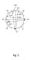
- FIG. 2 an embodiment of the present invention is shown in which in addition to the first light emitter 10, a second light emitter 17 is still present.
- the second light emitter 17 is arranged to emit light beams 200, 210, 220 that cross the tube and, if not scattered by an intermediate object, strike the light sensor 12A.
- the light sensor 12A may function as the scattered light detector 12 with respect to the light emitter 10. In this case, it may preferably be arranged between the light beams 17, unscattered light beams 200, 210, 220 and, if necessary, scattered light beam components (as in FIG FIG. 1B shown light beam portion 102) distinguished by the first light emitter 10 light beams 100, 101, 102 differ. This can be achieved by suitable modulation or temporal displacement of the emitted light beams.
- the device shown has further light detectors 13, 14, 15 and 16 which, with the above designations with respect to the light emitters 10 and 17, can each be set up as a light sensor and / or as a scattered-light detector.
Landscapes
- Physics & Mathematics (AREA)
- Health & Medical Sciences (AREA)
- Life Sciences & Earth Sciences (AREA)
- Chemical & Material Sciences (AREA)
- Analytical Chemistry (AREA)
- Biochemistry (AREA)
- General Health & Medical Sciences (AREA)
- General Physics & Mathematics (AREA)
- Immunology (AREA)
- Pathology (AREA)
- Investigating Or Analysing Materials By Optical Means (AREA)
Priority Applications (1)
| Application Number | Priority Date | Filing Date | Title |
|---|---|---|---|
| EP12006547.9A EP2708872A1 (fr) | 2012-09-18 | 2012-09-18 | Procédé et dispositif de détection d'objets se déplaçant dans un flux de gaz |
Applications Claiming Priority (1)
| Application Number | Priority Date | Filing Date | Title |
|---|---|---|---|
| EP12006547.9A EP2708872A1 (fr) | 2012-09-18 | 2012-09-18 | Procédé et dispositif de détection d'objets se déplaçant dans un flux de gaz |
Publications (1)
| Publication Number | Publication Date |
|---|---|
| EP2708872A1 true EP2708872A1 (fr) | 2014-03-19 |
Family
ID=47189662
Family Applications (1)
| Application Number | Title | Priority Date | Filing Date |
|---|---|---|---|
| EP12006547.9A Withdrawn EP2708872A1 (fr) | 2012-09-18 | 2012-09-18 | Procédé et dispositif de détection d'objets se déplaçant dans un flux de gaz |
Country Status (1)
| Country | Link |
|---|---|
| EP (1) | EP2708872A1 (fr) |
Citations (6)
| Publication number | Priority date | Publication date | Assignee | Title |
|---|---|---|---|---|
| US3775013A (en) * | 1971-11-17 | 1973-11-27 | Monitor Techn Inc | Optical turbidimeter apparatus |
| GB2251682A (en) * | 1990-12-03 | 1992-07-15 | Great Lakes Instruments Inc | Turbidimeter |
| EP1061356A2 (fr) * | 1999-06-14 | 2000-12-20 | General Electric Company | Détecteur des particules en ligne |
| WO2001063253A1 (fr) * | 2000-02-24 | 2001-08-30 | Eppendorf Ag | Systeme de mesure optique |
| GB2426579A (en) * | 2005-05-28 | 2006-11-29 | Schlumberger Holdings | Devices and methods for quantification of liquids in gas-condensate wells |
| EP1972925A1 (fr) * | 2005-12-28 | 2008-09-24 | Toyota Jidosha Kabushiki Kaisha | Dispositif et procede d'analyse de gaz d'echappement |
-
2012
- 2012-09-18 EP EP12006547.9A patent/EP2708872A1/fr not_active Withdrawn
Patent Citations (6)
| Publication number | Priority date | Publication date | Assignee | Title |
|---|---|---|---|---|
| US3775013A (en) * | 1971-11-17 | 1973-11-27 | Monitor Techn Inc | Optical turbidimeter apparatus |
| GB2251682A (en) * | 1990-12-03 | 1992-07-15 | Great Lakes Instruments Inc | Turbidimeter |
| EP1061356A2 (fr) * | 1999-06-14 | 2000-12-20 | General Electric Company | Détecteur des particules en ligne |
| WO2001063253A1 (fr) * | 2000-02-24 | 2001-08-30 | Eppendorf Ag | Systeme de mesure optique |
| GB2426579A (en) * | 2005-05-28 | 2006-11-29 | Schlumberger Holdings | Devices and methods for quantification of liquids in gas-condensate wells |
| EP1972925A1 (fr) * | 2005-12-28 | 2008-09-24 | Toyota Jidosha Kabushiki Kaisha | Dispositif et procede d'analyse de gaz d'echappement |
Similar Documents
| Publication | Publication Date | Title |
|---|---|---|
| DE69722942T2 (de) | Detektion gefährlicher schwebender fasern | |
| DE102004021663A1 (de) | Umgebungsbedingungsdetektor mit mehreren Sensoren und einer einzelnen Steuereinheit | |
| EP1389331A1 (fr) | Systeme de detection d'incendie a auto-aspiration | |
| WO2013024166A1 (fr) | Procédé et dispositif de détermination de la taille d'une particule transparente | |
| DE102008009006A1 (de) | Optischer Wettersensor | |
| EP1176414B1 (fr) | Procédé et dispositif pour déterminer des paramètres physiques collectifs des particules dans les gaz | |
| DE112020002849T5 (de) | Optischer Partikelsensor | |
| EP2624229A1 (fr) | Mesure du flux d'air permettant de contrôler l'état de bon fonctionnement d'un détecteur de type chambre à fumée. | |
| EP1224641B2 (fr) | Dispositif de detection de fumee | |
| DE102014215727B4 (de) | Verfahren zur Überwachung des Betriebszustands eines Oberflächen-Inspektionssystems zum Nachweis von Defekten auf der Oberfläche von Halbleiterscheiben | |
| EP1039426A2 (fr) | Dispositif pour détecter de la fumée | |
| AT516759B1 (de) | Vorrichtung und Verfahren zur Ermittlung der Anzahl an Feststoffpartikeln in einem Fluidstrom | |
| EP3096130B1 (fr) | Dispositif destine a l'identification d'aerosols | |
| WO2021191104A1 (fr) | Procédé et dispositif de mesure pour déterminer la vitesse de particules d'un aérosol | |
| WO2016180907A1 (fr) | Dispositif et procédé pour le comptage et/ou la mesure de particules dans un flux de liquide | |
| EP3413014A1 (fr) | Procédé et dispositif de détection et de mesure d'objets | |
| DE10161502A1 (de) | Verfahren und Vorrichtung zur kontinuierlichen Ermittlung und Lokalisierung von Fadenfehlern einer in einer Ebene laufenden Fadenschar | |
| EP2883078B1 (fr) | Procédé et dispositif de détection d'objets en mouvement dans un courant gazeux lors d'une séparation cryogénique de gaz | |
| EP2708872A1 (fr) | Procédé et dispositif de détection d'objets se déplaçant dans un flux de gaz | |
| EP1913565B1 (fr) | Dispositif de detection | |
| EP3955226B1 (fr) | Système de détection des particules d'admission pourvu de système de guidage de lumière | |
| DE102013202423A1 (de) | Partikeldetektor und Verfahren zur Detektion von Partikeln | |
| EP1360669B1 (fr) | Procede et dispositif pour surveiller des installations souterraines | |
| EP2053574B1 (fr) | Détecteur de fumée avec répression de particules | |
| EP3922986B1 (fr) | Procédé de mesure de taux de comptage ou de grandeurs mesurées en fonction des taux de comptage et dispositif de mesure de taux de comptage ou de grandeurs mesurées en fonction des taux de comptage |
Legal Events
| Date | Code | Title | Description |
|---|---|---|---|
| PUAI | Public reference made under article 153(3) epc to a published international application that has entered the european phase |
Free format text: ORIGINAL CODE: 0009012 |
|
| AK | Designated contracting states |
Kind code of ref document: A1 Designated state(s): AL AT BE BG CH CY CZ DE DK EE ES FI FR GB GR HR HU IE IS IT LI LT LU LV MC MK MT NL NO PL PT RO RS SE SI SK SM TR |
|
| AX | Request for extension of the european patent |
Extension state: BA ME |
|
| STAA | Information on the status of an ep patent application or granted ep patent |
Free format text: STATUS: THE APPLICATION IS DEEMED TO BE WITHDRAWN |
|
| 18D | Application deemed to be withdrawn |
Effective date: 20140920 |