EP2709113A1 - Câble sous-terrain - Google Patents
Câble sous-terrain Download PDFInfo
- Publication number
- EP2709113A1 EP2709113A1 EP13184916.8A EP13184916A EP2709113A1 EP 2709113 A1 EP2709113 A1 EP 2709113A1 EP 13184916 A EP13184916 A EP 13184916A EP 2709113 A1 EP2709113 A1 EP 2709113A1
- Authority
- EP
- European Patent Office
- Prior art keywords
- difluoroethylene
- cable
- vinyl ether
- monomer
- trifluoroethylene
- Prior art date
- Legal status (The legal status is an assumption and is not a legal conclusion. Google has not performed a legal analysis and makes no representation as to the accuracy of the status listed.)
- Granted
Links
- 229920002313 fluoropolymer Polymers 0.000 claims abstract description 119
- 239000004811 fluoropolymer Substances 0.000 claims abstract description 119
- 239000004020 conductor Substances 0.000 claims abstract description 99
- 239000012212 insulator Substances 0.000 claims abstract description 88
- 238000000034 method Methods 0.000 claims abstract description 26
- 230000005611 electricity Effects 0.000 claims abstract description 18
- 238000004519 manufacturing process Methods 0.000 claims abstract description 8
- 239000000178 monomer Substances 0.000 claims description 227
- 125000003963 dichloro group Chemical group Cl* 0.000 claims description 80
- -1 1,1,2,2-tetrafluoroethylene, 1-fluoroethylene, 1,1-difluoroethylene, 1,2-difluoroethylene, 1,1,2-trifluoroethylene Chemical group 0.000 claims description 74
- HCDGVLDPFQMKDK-UHFFFAOYSA-N hexafluoropropylene Chemical compound FC(F)=C(F)C(F)(F)F HCDGVLDPFQMKDK-UHFFFAOYSA-N 0.000 claims description 65
- PXHVJJICTQNCMI-UHFFFAOYSA-N Nickel Chemical compound [Ni] PXHVJJICTQNCMI-UHFFFAOYSA-N 0.000 claims description 57
- 238000009434 installation Methods 0.000 claims description 56
- WFLOTYSKFUPZQB-UHFFFAOYSA-N 1,2-difluoroethene Chemical group FC=CF WFLOTYSKFUPZQB-UHFFFAOYSA-N 0.000 claims description 50
- LOJJTTDNNWYSGX-UHFFFAOYSA-N 1,1,1,2,2,3,3,4,4-nonafluoro-4-(1,1,2,2,3,3,4,4,4-nonafluorobutoxy)butane Chemical compound FC(F)(F)C(F)(F)C(F)(F)C(F)(F)OC(F)(F)C(F)(F)C(F)(F)C(F)(F)F LOJJTTDNNWYSGX-UHFFFAOYSA-N 0.000 claims description 40
- WUMVZXWBOFOYAW-UHFFFAOYSA-N 1,2,3,3,4,4,4-heptafluoro-1-(1,2,3,3,4,4,4-heptafluorobut-1-enoxy)but-1-ene Chemical compound FC(F)(F)C(F)(F)C(F)=C(F)OC(F)=C(F)C(F)(F)C(F)(F)F WUMVZXWBOFOYAW-UHFFFAOYSA-N 0.000 claims description 40
- BZPCMSSQHRAJCC-UHFFFAOYSA-N 1,2,3,3,4,4,5,5,5-nonafluoro-1-(1,2,3,3,4,4,5,5,5-nonafluoropent-1-enoxy)pent-1-ene Chemical compound FC(F)(F)C(F)(F)C(F)(F)C(F)=C(F)OC(F)=C(F)C(F)(F)C(F)(F)C(F)(F)F BZPCMSSQHRAJCC-UHFFFAOYSA-N 0.000 claims description 40
- UUAGAQFQZIEFAH-UHFFFAOYSA-N chlorotrifluoroethylene Chemical group FC(F)=C(F)Cl UUAGAQFQZIEFAH-UHFFFAOYSA-N 0.000 claims description 40
- BLTXWCKMNMYXEA-UHFFFAOYSA-N 1,1,2-trifluoro-2-(trifluoromethoxy)ethene Chemical compound FC(F)=C(F)OC(F)(F)F BLTXWCKMNMYXEA-UHFFFAOYSA-N 0.000 claims description 30
- 229910052759 nickel Inorganic materials 0.000 claims description 29
- 230000004888 barrier function Effects 0.000 claims description 27
- XEEYBQQBJWHFJM-UHFFFAOYSA-N Iron Chemical compound [Fe] XEEYBQQBJWHFJM-UHFFFAOYSA-N 0.000 claims description 26
- 229920001343 polytetrafluoroethylene Polymers 0.000 claims description 26
- 239000004810 polytetrafluoroethylene Substances 0.000 claims description 25
- RYGMFSIKBFXOCR-UHFFFAOYSA-N Copper Chemical compound [Cu] RYGMFSIKBFXOCR-UHFFFAOYSA-N 0.000 claims description 24
- 239000010949 copper Substances 0.000 claims description 24
- 229910052802 copper Inorganic materials 0.000 claims description 24
- 229910045601 alloy Inorganic materials 0.000 claims description 23
- 239000000956 alloy Substances 0.000 claims description 23
- 239000000654 additive Substances 0.000 claims description 21
- 239000012535 impurity Substances 0.000 claims description 21
- VYZAMTAEIAYCRO-UHFFFAOYSA-N Chromium Chemical compound [Cr] VYZAMTAEIAYCRO-UHFFFAOYSA-N 0.000 claims description 18
- 229910052804 chromium Inorganic materials 0.000 claims description 18
- 239000011651 chromium Substances 0.000 claims description 18
- WPBNNNQJVZRUHP-UHFFFAOYSA-L manganese(2+);methyl n-[[2-(methoxycarbonylcarbamothioylamino)phenyl]carbamothioyl]carbamate;n-[2-(sulfidocarbothioylamino)ethyl]carbamodithioate Chemical compound [Mn+2].[S-]C(=S)NCCNC([S-])=S.COC(=O)NC(=S)NC1=CC=CC=C1NC(=S)NC(=O)OC WPBNNNQJVZRUHP-UHFFFAOYSA-L 0.000 claims description 15
- 239000004411 aluminium Substances 0.000 claims description 14
- 229910052782 aluminium Inorganic materials 0.000 claims description 14
- XAGFODPZIPBFFR-UHFFFAOYSA-N aluminium Chemical compound [Al] XAGFODPZIPBFFR-UHFFFAOYSA-N 0.000 claims description 14
- RTAQQCXQSZGOHL-UHFFFAOYSA-N Titanium Chemical compound [Ti] RTAQQCXQSZGOHL-UHFFFAOYSA-N 0.000 claims description 13
- 229910017052 cobalt Inorganic materials 0.000 claims description 13
- 239000010941 cobalt Substances 0.000 claims description 13
- GUTLYIVDDKVIGB-UHFFFAOYSA-N cobalt atom Chemical compound [Co] GUTLYIVDDKVIGB-UHFFFAOYSA-N 0.000 claims description 13
- 229910052742 iron Inorganic materials 0.000 claims description 13
- 239000010936 titanium Substances 0.000 claims description 13
- 229910052719 titanium Inorganic materials 0.000 claims description 13
- 229920001577 copolymer Polymers 0.000 claims description 12
- ZOKXTWBITQBERF-UHFFFAOYSA-N Molybdenum Chemical compound [Mo] ZOKXTWBITQBERF-UHFFFAOYSA-N 0.000 claims description 11
- 229910052750 molybdenum Inorganic materials 0.000 claims description 11
- 239000011733 molybdenum Substances 0.000 claims description 11
- 229910052758 niobium Inorganic materials 0.000 claims description 11
- 239000010955 niobium Substances 0.000 claims description 11
- GUCVJGMIXFAOAE-UHFFFAOYSA-N niobium atom Chemical compound [Nb] GUCVJGMIXFAOAE-UHFFFAOYSA-N 0.000 claims description 11
- ZOXJGFHDIHLPTG-UHFFFAOYSA-N Boron Chemical compound [B] ZOXJGFHDIHLPTG-UHFFFAOYSA-N 0.000 claims description 3
- OKTJSMMVPCPJKN-UHFFFAOYSA-N Carbon Chemical compound [C] OKTJSMMVPCPJKN-UHFFFAOYSA-N 0.000 claims description 3
- OAICVXFJPJFONN-UHFFFAOYSA-N Phosphorus Chemical compound [P] OAICVXFJPJFONN-UHFFFAOYSA-N 0.000 claims description 3
- XUIMIQQOPSSXEZ-UHFFFAOYSA-N Silicon Chemical compound [Si] XUIMIQQOPSSXEZ-UHFFFAOYSA-N 0.000 claims description 3
- NINIDFKCEFEMDL-UHFFFAOYSA-N Sulfur Chemical compound [S] NINIDFKCEFEMDL-UHFFFAOYSA-N 0.000 claims description 3
- 239000005864 Sulphur Substances 0.000 claims description 3
- 229910052796 boron Inorganic materials 0.000 claims description 3
- 229910052799 carbon Inorganic materials 0.000 claims description 3
- 229910052698 phosphorus Inorganic materials 0.000 claims description 3
- 239000011574 phosphorus Substances 0.000 claims description 3
- 239000010703 silicon Substances 0.000 claims description 3
- 229910052710 silicon Inorganic materials 0.000 claims description 3
- 239000010410 layer Substances 0.000 description 128
- 238000009413 insulation Methods 0.000 description 24
- BFKJFAAPBSQJPD-UHFFFAOYSA-N tetrafluoroethene Chemical group FC(F)=C(F)F BFKJFAAPBSQJPD-UHFFFAOYSA-N 0.000 description 18
- WFLOTYSKFUPZQB-OWOJBTEDSA-N (e)-1,2-difluoroethene Chemical group F\C=C\F WFLOTYSKFUPZQB-OWOJBTEDSA-N 0.000 description 10
- LFMIQNJMJJKICW-UHFFFAOYSA-N 1,1,2-trichloro-2-fluoroethene Chemical group FC(Cl)=C(Cl)Cl LFMIQNJMJJKICW-UHFFFAOYSA-N 0.000 description 10
- MIZLGWKEZAPEFJ-UHFFFAOYSA-N 1,1,2-trifluoroethene Chemical group FC=C(F)F MIZLGWKEZAPEFJ-UHFFFAOYSA-N 0.000 description 10
- BQCIDUSAKPWEOX-UHFFFAOYSA-N 1,1-Difluoroethene Chemical group FC(F)=C BQCIDUSAKPWEOX-UHFFFAOYSA-N 0.000 description 10
- 229920000840 ethylene tetrafluoroethylene copolymer Polymers 0.000 description 10
- XUCNUKMRBVNAPB-UHFFFAOYSA-N fluoroethene Chemical group FC=C XUCNUKMRBVNAPB-UHFFFAOYSA-N 0.000 description 10
- CSJWOWRPMBXQLD-UHFFFAOYSA-N perfluoromethylvinylether group Chemical group FC(=C(C(F)(F)F)F)OC(=C(F)C(F)(F)F)F CSJWOWRPMBXQLD-UHFFFAOYSA-N 0.000 description 10
- VGGSQFUCUMXWEO-UHFFFAOYSA-N Ethene Chemical compound C=C VGGSQFUCUMXWEO-UHFFFAOYSA-N 0.000 description 9
- 239000005977 Ethylene Substances 0.000 description 9
- 239000000463 material Substances 0.000 description 9
- 229910000881 Cu alloy Inorganic materials 0.000 description 7
- RWSOTUBLDIXVET-UHFFFAOYSA-N Dihydrogen sulfide Chemical compound S RWSOTUBLDIXVET-UHFFFAOYSA-N 0.000 description 6
- 230000001419 dependent effect Effects 0.000 description 5
- 229920000642 polymer Polymers 0.000 description 5
- QQONPFPTGQHPMA-UHFFFAOYSA-N propylene Natural products CC=C QQONPFPTGQHPMA-UHFFFAOYSA-N 0.000 description 5
- 125000004805 propylene group Chemical group [H]C([H])([H])C([H])([*:1])C([H])([H])[*:2] 0.000 description 5
- 230000002829 reductive effect Effects 0.000 description 5
- 229910001220 stainless steel Inorganic materials 0.000 description 5
- 239000010935 stainless steel Substances 0.000 description 5
- 229910000831 Steel Inorganic materials 0.000 description 4
- 230000005684 electric field Effects 0.000 description 4
- 239000010959 steel Substances 0.000 description 4
- 238000005336 cracking Methods 0.000 description 3
- 238000001125 extrusion Methods 0.000 description 3
- 229910052731 fluorine Inorganic materials 0.000 description 3
- 239000003921 oil Substances 0.000 description 3
- 239000007787 solid Substances 0.000 description 3
- 239000000126 substance Substances 0.000 description 3
- 229920002943 EPDM rubber Polymers 0.000 description 2
- 230000015556 catabolic process Effects 0.000 description 2
- 238000006731 degradation reaction Methods 0.000 description 2
- 238000009826 distribution Methods 0.000 description 2
- 125000001153 fluoro group Chemical group F* 0.000 description 2
- 230000017525 heat dissipation Effects 0.000 description 2
- 238000002844 melting Methods 0.000 description 2
- 230000008018 melting Effects 0.000 description 2
- 229910052751 metal Inorganic materials 0.000 description 2
- 238000013021 overheating Methods 0.000 description 2
- 230000001590 oxidative effect Effects 0.000 description 2
- 229920000915 polyvinyl chloride Polymers 0.000 description 2
- 239000004800 polyvinyl chloride Substances 0.000 description 2
- 230000002040 relaxant effect Effects 0.000 description 2
- 238000004804 winding Methods 0.000 description 2
- 229910000851 Alloy steel Inorganic materials 0.000 description 1
- 229910000952 Be alloy Inorganic materials 0.000 description 1
- 229910001369 Brass Inorganic materials 0.000 description 1
- 229910000570 Cupronickel Inorganic materials 0.000 description 1
- 229920006358 Fluon Polymers 0.000 description 1
- PXGOKWXKJXAPGV-UHFFFAOYSA-N Fluorine Chemical compound FF PXGOKWXKJXAPGV-UHFFFAOYSA-N 0.000 description 1
- 229920006367 Neoflon Polymers 0.000 description 1
- 241001275902 Parabramis pekinensis Species 0.000 description 1
- 239000004809 Teflon Substances 0.000 description 1
- 229920006355 Tefzel Polymers 0.000 description 1
- 239000002253 acid Substances 0.000 description 1
- 150000007513 acids Chemical class 0.000 description 1
- 239000002585 base Substances 0.000 description 1
- 238000005452 bending Methods 0.000 description 1
- 230000015572 biosynthetic process Effects 0.000 description 1
- 239000010951 brass Substances 0.000 description 1
- 239000003518 caustics Substances 0.000 description 1
- 238000002144 chemical decomposition reaction Methods 0.000 description 1
- 239000011248 coating agent Substances 0.000 description 1
- 238000000576 coating method Methods 0.000 description 1
- 238000010276 construction Methods 0.000 description 1
- YOCUPQPZWBBYIX-UHFFFAOYSA-N copper nickel Chemical compound [Ni].[Cu] YOCUPQPZWBBYIX-UHFFFAOYSA-N 0.000 description 1
- 238000005260 corrosion Methods 0.000 description 1
- 230000007797 corrosion Effects 0.000 description 1
- 238000000354 decomposition reaction Methods 0.000 description 1
- 230000000694 effects Effects 0.000 description 1
- 229920001971 elastomer Polymers 0.000 description 1
- 238000010292 electrical insulation Methods 0.000 description 1
- QHSJIZLJUFMIFP-UHFFFAOYSA-N ethene;1,1,2,2-tetrafluoroethene Chemical compound C=C.FC(F)=C(F)F QHSJIZLJUFMIFP-UHFFFAOYSA-N 0.000 description 1
- 230000001747 exhibiting effect Effects 0.000 description 1
- 239000011737 fluorine Substances 0.000 description 1
- 238000005187 foaming Methods 0.000 description 1
- 238000005755 formation reaction Methods 0.000 description 1
- 239000007789 gas Substances 0.000 description 1
- 230000005484 gravity Effects 0.000 description 1
- 230000020169 heat generation Effects 0.000 description 1
- 229910001055 inconels 600 Inorganic materials 0.000 description 1
- 229910001063 inconels 617 Inorganic materials 0.000 description 1
- 229910001119 inconels 625 Inorganic materials 0.000 description 1
- 229910000816 inconels 718 Inorganic materials 0.000 description 1
- 229910001090 inconels X-750 Inorganic materials 0.000 description 1
- 239000012774 insulation material Substances 0.000 description 1
- 239000007788 liquid Substances 0.000 description 1
- 239000002184 metal Substances 0.000 description 1
- 125000000956 methoxy group Chemical group [H]C([H])([H])O* 0.000 description 1
- 238000012806 monitoring device Methods 0.000 description 1
- 125000006340 pentafluoro ethyl group Chemical group FC(F)(F)C(F)(F)* 0.000 description 1
- 230000002028 premature Effects 0.000 description 1
- 239000011241 protective layer Substances 0.000 description 1
- 238000005086 pumping Methods 0.000 description 1
- 230000002787 reinforcement Effects 0.000 description 1
- 239000005060 rubber Substances 0.000 description 1
- 238000004513 sizing Methods 0.000 description 1
- 239000002904 solvent Substances 0.000 description 1
- 230000002459 sustained effect Effects 0.000 description 1
- 229920003051 synthetic elastomer Polymers 0.000 description 1
- 239000005061 synthetic rubber Substances 0.000 description 1
- 125000000876 trifluoromethoxy group Chemical group FC(F)(F)O* 0.000 description 1
Images
Classifications
-
- H—ELECTRICITY
- H02—GENERATION; CONVERSION OR DISTRIBUTION OF ELECTRIC POWER
- H02G—INSTALLATION OF ELECTRIC CABLES OR LINES, OR OF COMBINED OPTICAL AND ELECTRIC CABLES OR LINES
- H02G9/00—Installations of electric cables or lines in or on the ground or water
- H02G9/02—Installations of electric cables or lines in or on the ground or water laid directly in or on the ground, river-bed or sea-bottom; Coverings therefor, e.g. tile
-
- H—ELECTRICITY
- H01—ELECTRIC ELEMENTS
- H01B—CABLES; CONDUCTORS; INSULATORS; SELECTION OF MATERIALS FOR THEIR CONDUCTIVE, INSULATING OR DIELECTRIC PROPERTIES
- H01B3/00—Insulators or insulating bodies characterised by the insulating materials; Selection of materials for their insulating or dielectric properties
- H01B3/18—Insulators or insulating bodies characterised by the insulating materials; Selection of materials for their insulating or dielectric properties mainly consisting of organic substances
- H01B3/30—Insulators or insulating bodies characterised by the insulating materials; Selection of materials for their insulating or dielectric properties mainly consisting of organic substances plastics; resins; waxes
- H01B3/44—Insulators or insulating bodies characterised by the insulating materials; Selection of materials for their insulating or dielectric properties mainly consisting of organic substances plastics; resins; waxes vinyl resins; acrylic resins
- H01B3/443—Insulators or insulating bodies characterised by the insulating materials; Selection of materials for their insulating or dielectric properties mainly consisting of organic substances plastics; resins; waxes vinyl resins; acrylic resins from vinylhalogenides or other halogenoethylenic compounds
- H01B3/445—Insulators or insulating bodies characterised by the insulating materials; Selection of materials for their insulating or dielectric properties mainly consisting of organic substances plastics; resins; waxes vinyl resins; acrylic resins from vinylhalogenides or other halogenoethylenic compounds from vinylfluorides or other fluoroethylenic compounds
-
- H—ELECTRICITY
- H01—ELECTRIC ELEMENTS
- H01B—CABLES; CONDUCTORS; INSULATORS; SELECTION OF MATERIALS FOR THEIR CONDUCTIVE, INSULATING OR DIELECTRIC PROPERTIES
- H01B13/00—Apparatus or processes specially adapted for manufacturing conductors or cables
- H01B13/016—Apparatus or processes specially adapted for manufacturing conductors or cables for manufacturing co-axial cables
-
- H—ELECTRICITY
- H01—ELECTRIC ELEMENTS
- H01B—CABLES; CONDUCTORS; INSULATORS; SELECTION OF MATERIALS FOR THEIR CONDUCTIVE, INSULATING OR DIELECTRIC PROPERTIES
- H01B7/00—Insulated conductors or cables characterised by their form
- H01B7/17—Protection against damage caused by external factors, e.g. sheaths or armouring
- H01B7/18—Protection against damage caused by wear, mechanical force or pressure; Sheaths; Armouring
- H01B7/22—Metal wires or tapes, e.g. made of steel
- H01B7/226—Helicoidally wound metal wires or tapes
-
- H—ELECTRICITY
- H01—ELECTRIC ELEMENTS
- H01B—CABLES; CONDUCTORS; INSULATORS; SELECTION OF MATERIALS FOR THEIR CONDUCTIVE, INSULATING OR DIELECTRIC PROPERTIES
- H01B7/00—Insulated conductors or cables characterised by their form
- H01B7/17—Protection against damage caused by external factors, e.g. sheaths or armouring
- H01B7/28—Protection against damage caused by moisture, corrosion, chemical attack or weather
-
- H—ELECTRICITY
- H01—ELECTRIC ELEMENTS
- H01B—CABLES; CONDUCTORS; INSULATORS; SELECTION OF MATERIALS FOR THEIR CONDUCTIVE, INSULATING OR DIELECTRIC PROPERTIES
- H01B7/00—Insulated conductors or cables characterised by their form
- H01B7/17—Protection against damage caused by external factors, e.g. sheaths or armouring
- H01B7/29—Protection against damage caused by extremes of temperature or by flame
-
- H—ELECTRICITY
- H01—ELECTRIC ELEMENTS
- H01B—CABLES; CONDUCTORS; INSULATORS; SELECTION OF MATERIALS FOR THEIR CONDUCTIVE, INSULATING OR DIELECTRIC PROPERTIES
- H01B7/00—Insulated conductors or cables characterised by their form
- H01B7/04—Flexible cables, conductors, or cords, e.g. trailing cables
- H01B7/046—Flexible cables, conductors, or cords, e.g. trailing cables attached to objects sunk in bore holes, e.g. well drilling means, well pumps
-
- Y—GENERAL TAGGING OF NEW TECHNOLOGICAL DEVELOPMENTS; GENERAL TAGGING OF CROSS-SECTIONAL TECHNOLOGIES SPANNING OVER SEVERAL SECTIONS OF THE IPC; TECHNICAL SUBJECTS COVERED BY FORMER USPC CROSS-REFERENCE ART COLLECTIONS [XRACs] AND DIGESTS
- Y02—TECHNOLOGIES OR APPLICATIONS FOR MITIGATION OR ADAPTATION AGAINST CLIMATE CHANGE
- Y02A—TECHNOLOGIES FOR ADAPTATION TO CLIMATE CHANGE
- Y02A30/00—Adapting or protecting infrastructure or their operation
- Y02A30/14—Extreme weather resilient electric power supply systems, e.g. strengthening power lines or underground power cables
-
- Y—GENERAL TAGGING OF NEW TECHNOLOGICAL DEVELOPMENTS; GENERAL TAGGING OF CROSS-SECTIONAL TECHNOLOGIES SPANNING OVER SEVERAL SECTIONS OF THE IPC; TECHNICAL SUBJECTS COVERED BY FORMER USPC CROSS-REFERENCE ART COLLECTIONS [XRACs] AND DIGESTS
- Y10—TECHNICAL SUBJECTS COVERED BY FORMER USPC
- Y10T—TECHNICAL SUBJECTS COVERED BY FORMER US CLASSIFICATION
- Y10T29/00—Metal working
- Y10T29/49—Method of mechanical manufacture
- Y10T29/49002—Electrical device making
- Y10T29/49117—Conductor or circuit manufacturing
- Y10T29/49123—Co-axial cable
Definitions
- the present invention relates to a cable for conducting electricity and carrying tension, and is particularly useful for subterranean applications.
- the invention also relates to an insulation layer to electrically insulate the conductor component of such cables.
- Devices are routinely placed in wellbores during the course of oil exploration or production. Such devices are often powered by electricity, which is transmitted by power cables from the surface. Devices include monitoring devices (to provide information regarding the subterranean formations surrounding the wellbore) and pumps (to aid in pumping oil to the surface).
- the downhole environment and the power requirements of the devices present a number of challenges when providing such cables.
- the downhole environment may be corrosive (for instance, the environment may exhibit extremes of pH's, or may be oxidative or reductive, for instance, if hydrogen sulphide is present), and thus cables need to be resistant to such challenges.
- Downhole temperatures can vary with depth; typically temperatures increases with increasing depth, meaning the components of the cable must function properly in a wide range of temperatures. If the power cable is also used to suspend, or lower and lift devices into and out of the wellbore, the power cable must be strong enough to support the devices.
- cables are strong enough to support the devices, an important consideration is that they must be strong enough to support their own weight: where the depth of wellbore is several hundreds, if not thousands of meters long, the self-weight of the cable itself may be substantial.
- the cable must also be mechanically robust and resilient so that an operator can use it in the field repeatedly without concern that it will fail. Most importantly, the cable must be capable of providing sufficient electrical power to any device downhole.
- wellbore environments are typically restricted in terms of space, which in turn places restrictions on the maximum allowable cable diameter.
- a typical wellbore may have an inner diameter as small as around 5 inches, and the maximum diameters of cables are typically restricted to a fraction of the wellbore diameter.
- the present invention provides a cable comprising a first conductor, a first insulator layer and a first plurality of wires, wherein the first conductor, the first insulator and the first plurality of wires extend along an longitudinal axis of the cable, wherein the first insulator layer is axially external to the conductor, and the first plurality of wires is axially external to the first insulator, and wherein the first insulator layer comprises a first fluoropolymer.
- the present invention provides use of a fluoropolymer as an insulator in an armoured cable for use downhole.
- the present invention provides a method of manufacturing a cable of the invention, comprising disposing the first insulator layer around the first conductor and along a longitudinal axis thereof, and disposing the first plurality of wires around the first insulator layer and along a longitudinal axis thereof, wherein the first insulator layer comprises the first fluoropolymer.
- the present invention provides a method of transmitting electricity, comprising connecting a first installation or device with a second installation or device with a cable according to the present invention, and transmitting electricity from the first installation or device to the second installation or device through the cable, wherein the first installation or device is in a wellbore.
- the present invention provides a method of suspending a first device or installation in a wellbore, comprising providing a cable of the invention, securing a first end of the cable to the first device or installation, securing a second end of the cable to a second device or installation, and suspending the first device or installation in the wellbore.
- the present invention relates to a cable for conducting electricity, in particular, for cables used in subterranean applications.
- the invention also relates to an insulation layer to insulate the conductor component of such cables.
- the cables of the present invention are particularly useful for providing DC (direct current) electricity to downhole devices, but may equally be used for convey AC (alternative current) electricity.
- the cable may be used to power any downhole device that uses electricity, and is particularly useful for powering ESP's (electrical submersible pumps).
- the present invention is particularly useful when configured as a DC cable for powering ESP's, since it is believed that no DC ESP cables are currently thought to be available.
- the cable of the present invention is capable of operating at around 5kV to 6kV, with a current carrying capacity of 100A.
- the cable can also be subjected to relatively high temperatures. For instance, the cable may be used in downhole temperatures of up to 80°C, up to 90°C, up to 100°C, up to 120°C, up to 130°C, up to 140°C, or up to 150°C.
- the cable may be used in corrosive environments, for instance, in low or high pH's, or in oxidative or reductive environments.
- the cable is able to tolerate exposure to hydrogen sulphide of around 4%-6% (mol).
- the cable may also be subjected to working loads of at least 10,0001bs (44.5kN).
- present invention provides a DC cable for powering an ESP.
- the cable of the present invention comprises a first conductor, a first insulator layer and a first plurality of wires, wherein the first conductor, the first insulator and the first plurality of wires extend along an longitudinal axis of the cable, wherein the first insulator layer is axially external to the conductor, and the first plurality of wires is axially external to the first insulator, and wherein the first insulator layer comprises a first fluoropolymer.
- the first conductor of the present invention is sized to allow for sustained and safe level of current which does not lead to overheating of the cable, so that the maximum allowable operating temperature is not exceeded. Overheating can lead to a number of problems, such as premature degradation and break down of the insulation layers. Other factors which determine conductor sizing include the operating environment, expected number of flex cycles during operation, mechanical capacity, the cable type and its service conditions.
- the normal maximum continuous rating of the cable is dependent on a number of factors. The most important of these is the maximum permissible conductor temperature rise (above ambient temperature).
- the maximum current rating is the loading (in amperes) which, when applied continuously until steady state conditions are reached, will produce the maximum allowable conductor temperature.
- Steady state is reached when the rate of heat generation in the cable is equal to the rate of heat dissipation from the cable's surface. This state is the primary condition considered when calculating current rating.
- the resistance of the first conductor should be as low as possible to minimize power losses from the conductors.
- the first conductor and/or the second comprises copper or copper alloy.
- Copper has many excellent properties that make is a suitable material for a conductor, such as excellent conductivity and mechanical strength, and thus is the most preferred material for use as the first or second conductor. Different grades of copper may be used if desired (e.g. UNS C11000 or C10300 - note “UNS” stand for "unified numbering system”). Copper alloys such as copper beryllium alloys (e.g. UNS C17000), copper brass alloys (e.g. UNS C26000), copper nickel alloys (e.g. UNS C71500 or C71640), copper aluminium brasses (e.g. UNS C68800) may also be used for the first or second conductors.
- copper beryllium alloys e.g. UNS C17000
- copper brass alloys e.g. UNS C26000
- copper nickel alloys e.g. UNS C71500 or C71640
- copper aluminium brasses e.
- Such alloys may provide slightly improved mechanical characteristics (such as higher tensile and fatigue strengths), but may do so at the expense of slightly lower thermal and electrical conductivities, or increased cost (This is accurate and correct to say).
- the skilled person will appreciate whether copper or a copper alloy should be used in the cable of the present invention.
- the first and/or second conductor may be formed of a single strand (also known as a solid core), or a plurality of stranded wires.
- the plurality of stranded wires is preferred, due to its improved flexibility and improved resistance to fatigue compared to solid core configurations.
- the plurality of wires may also be braided, since braids may further improve the resistance of the conductor to fatigue.
- the braid configuration provides good electrical and mechanical performance, at the same time exhibiting good resistance forces generated from repeated pulling and relaxing of the cable that can occur during operation.
- the first insulation layer of the present invention comprises a fluoropolymer.
- the first insulation layer may also consist of the fluoropolymer - that is to say, in this embodiment, the first layer may be formed of entirely from the first fluoropolymer.
- the first insulation layer serves to insulate and electrically isolate the first conductor from other components of the cable, such as the second conductor.
- the insulation thickness should be sufficient to sustain the electrical stresses developed during cable operation.
- fluoropolymers of the present invention will now be described. It will be appreciated that any description of fluoropolymer provided herein applies equally to the second, third and fourth fluoropolymers as well as the first fluoropolymer.
- Fluoropolymers are polymers based on fluorocarbons, which comprise strong carbon-fluorine bonds. Such polymers exhibit high resistance to solvents, acids and bases, as well as a good resistance to high temperatures. Some fluoropolymers are known for their non-stick and friction-reducing properties. The best known example of a fluoropolymer is polytetrafluoroethylene, commercially available as Teflon tm , which is commonly used as a non-stick coating for cookware. As used herein, the term "fluoropolymer” means any molecule comprising at least one repeating structural unit, where the at least one structural unit comprises at least one carbon-fluorine bond. Each structural unit is preferably covalently bonded to another structural unit.
- a typical fluoropolymer comprises a backbone of repeating -(CR 1 R 2 -CR 3 CR 4 )- structural units, where at least one of R 1 to R 4 is a fluorine atom.
- R 1 to R 4 is a fluorine atom
- possible moieties for the other R 1 to R 4 may be individually selected from -H, -CH 3 , -CF 3 , -Cl, -CCl 3 , -OCH 3 , -OCF 3 , -OCF 2 CF 3 , -OCF 2 CF 2 CF 3 , and -OCF 2 CF 2 CF 2 CF 3 .
- Each of the repeating structural units can be identical, Alternatively, there can be two, three or more distinct structural units; where there are two or more structural units, the resulting polymer is typically called a copolymer.
- the molecular sizes of the fluoropolymers of the present invention may vary, but are sufficiently large such that they are solid at the temperatures at which the cables of the present invention operate.
- the minimum melting temperatures of any fluoropolymer for use with the invention may be 225°C, 230 °C, 235 °C, 240 °C, 245 °C, 250 °C, 255 °C, or higher.
- the fluoropolymer is a polymer consisting of one monomer. In another embodiment the fluoropolymer is a copolymer comprising two different monomers. In another embodiment, the fluoropolymers may comprise three, four or more different monomers.
- the first insulator layer of the cable comprises a first fluoropolymer.
- the first insulator layer of the cable consists of a first fluoropolymer.
- the first fluoropolymer may comprise, or consist of, a first monomer.
- the first monomer may be selected from a group consisting of 1,1,2,2-tetrafluoroethylene, 1-fluoroethylene, 1,1-difluoroethylene, 1,2-difluoroethylene, 1,1,2-trifluoroethylene, hexafluoropropene, perfluoropropyl vinyl ether, perfluoroethyl vinyl ether, perfluoromethyl vinyl ether, perfluorobutyl ether, 1-chloro-1,2,2-trifluoroethylene, 1,1 dichloro 2,2, difluoroethylene, 1,2 dichloro 1,2, difluoroethylene, 1,1,2-trichloro-2-fluoroethylene, and hexafluoropropylene.
- the first fluoropolymer may further comprise a second monomer.
- the first fluoropolymer may consist of a first and a second fluoropolymer.
- the second monomer may be selected from a group consisting of ethylene, propylene, 1,1,2,2-tetrafluoroethylene, 1-fluoroethylene, 1,1-difluoroethylene, 1,2-difluoroethylene, 1,1,2-trifluoroethylene, hexafluoropropylene, perfluoropropyl vinyl ether, perfluoroethyl vinyl ether, perfluoromethyl vinyl ether, perfluorobutyl ether, 1-chloro-1,2,2-trifluoroethylene, 1,1 dichloro 2,2, difluoroethylene, 1,2 dichloro 1,2, difluoroethylene, 1,1,2-trichloro-2-fluoroethylene and hexafluoropropylene.
- the first fluoropolymer consists of two alternating monomers of ethylene and 1,1,2,2-tetrafluoroethylene, given by the structure (-CH 2 -CH 2 -CF 2 -CF 2 -) n .
- the fluoropolymer is also known as ETFE, or poly(ethylene-co-tetrafluoroethylene). This fluoropolymer is commercially available under the brand names Tefzel tm , Fluon tm , Neoflon tm and Texlon tm .
- ETFE exhibits a number of desirable properties, including a high melting temperature and high chemical resistance.
- the first fluoropolymer consists of one monomer of 1,1,2,2-tetrafluoroethylene.
- the structure of this polymer is (-CF 2 -CF 2 -) n , and is known as poly(1,1,2,2-tetrafluoroethylene), or PTFE.
- fluoropolymer in the first insulation layer (or in the second insulation layer) is unusual. This is because such materials are not typically used as insulators, since there are other insulator materials which are normally used. Usually synthetic rubber based materials such as PVC (polyvinyl chloride) or EPDM (ethylene propylene diene monomer) are used, since they provide acceptable insulation capabilities in most circumstances, but at a much reduced cost compared to fluoropolymers.
- fluoropolymers in particular, PTFE and ETFE
- provide better electrical insulation at a broader temperature range in particular, at elevated temperatures).
- fluoropolymers exhibit an improved decomposition temperature, durability and chemical resistance compared to known insulators, which in turn allows for a higher conductor temperature, which in turn allows for a greater steady state current.
- the higher resistance to thermal and chemical degradation also contributes to a reduced degradation of the insulating layer, thereby leading to an improved longevity of the cable itself.
- This higher resistance is also thought to allow the cable of the present invention, when used as an ESP cable, to be deployed downhole for relatively long periods compared to existing ESP cables.
- the present invention in turn allows for a thinner insulation layer than previously possible.
- fluoropolymer insulation provides higher hoop (circumferential) strength to the cable core than rubber insulation. This allows for a thinner insulation layer and in some cases removal of braided reinforcement which in turn allows for an improved capability of the cable to dissipate heat from the first conductor in the core of the cable, as well as allowing for a thicker central core conductor for a given diameter of cable (i.e.
- fluoropolymers exhibit other desirable characteristics making them suited for use as insulation for downhole cables. This includes low dielectric loss; good resistance to stress cracking; good resistance to chemicals; excellent mechanical properties, such as high tensile strength, 'cut-through' resistance, and low creep. Fluoropolymers exhibit an ideal level of stiffness that means it is not too stiff, such that the cable has enough flexibility for use, but not too flexible and soft, such that the insulation material does not extrude through the armour wires when the cable is under tension. Furthermore, fluoropolymers retain these properties at the higher temperatures, which means these advantages are seen across the range of temperatures seen downhole. ETFE is the a particularly advantageous fluoropolymer for use with the invention in this regard.
- the fluoropolymers used in any layer of any embodiment of the invention may be foamed or non-foamed. Foaming the fluoropolymers may reduce costs by reducing the amount of material used. However, the fluoropolymers used with the invention are preferably non-foamed, since the advantages listed above may be reduced to some extent when the fluoropolymer is foamed.
- cables of the present invention may need to be deployed in wellbores with diameter as low as 4.9 inches (12.5 cm), or even smaller, meaning the cables need to be as small as possible.
- the cable may further comprise a second conductor, wherein the second conductor extends along the longitudinal axis of the cable and is axially external to the first insulator.
- This second conductor preferably serves as a return conductor.
- the return conductor may provide a low DC resistance path for the electrical current running through the central conductor (if the cable is used to conduct DC current).
- the return current may flow through the second conductor at a lower voltage.
- the return conductor may also carry any fault current loads.
- the second conductor comprises a plurality of wires. This plurality of wires may be arranged to provide a layer surrounding the first insulator layer. In a preferred embodiment, the plurality of wires is braided.
- the cable further comprising a second insulator layer comprising a second fluoropolymer wherein the second insulator layer extends along the longitudinal axis of the cable and is axially external to the second conductor.
- the second insulator layer serves to insulate the second conductor from the other components of the cable axially external to the second conductor, such as the external armour or the surrounding environment.
- the second insulator layer of the cable comprises a second fluoropolymer.
- the second insulator layer of the cable consists of a second fluoropolymer.
- the second fluoropolymer may comprise, or consist of, a third monomer.
- the third monomer may be selected from a group consisting of 1,1,2,2-tetrafluoroethylene, 1-fluoroethylene, 1,1-difluoroethylene, 1,2-difluoroethylene, 1,1,2-trifluoroethylene, hexafluoropropene, perfluoropropyl vinyl ether, perfluoroethyl vinyl ether, perfluoromethyl vinyl ether, perfluorobutyl ether, 1-chloro-1,2,2-trifluoroethylene, 1,1 dichloro 2,2, difluoroethylene, 1,2 dichloro 1,2, difluoroethylene, 1,1,2-trichloro-2-fluoroethylene, and hexafluoropropylene.
- the second fluoropolymer may further comprise a fourth monomer.
- the second fluoropolymer may consist of a third and a fourth fluoropolymer.
- the fourth monomer may be selected from a group consisting of ethylene, propylene, 1,1,2,2-tetrafluoroethylene, 1-fluoroethylene, 1,1-difluoroethylene, 1,2-difluoroethylene, 1,1,2-trifluoroethylene, hexafluoropropylene, perfluoropropyl vinyl ether, perfluoroethyl vinyl ether, perfluoromethyl vinyl ether, perfluorobutyl ether, 1-chloro-1,2,2-trifluoroethylene, 1,1 dichloro 2,2, difluoroethylene, 1,2 dichloro 1,2, difluoroethylene, 1,1,2-trichloro-2-fluoroethylene and hexafluoropropylene.
- the second fluoropolymer consists of two alternating monomers of ethylene and 1,1,2,2-tetrafluoroethylene or most preferably, the second fluoropolymer consists of one monomer of 1,1,2,2-tetrafluoroethylene, i.e. PTFE.
- the cable may further comprises a barrier layer comprising a third fluoropolymer, wherein the barrier layer extends along the longitudinal axis of the cable and is axially external to the first and second insulator layer.
- the barrier layer provides a number of roles, including providing further insulation of the internal components of the cable from the external environment or any current in the armour, but also provides an impermeable layer to prevent ingress of any gas and liquid into the interior of the cable, and to protect the internal conductors and insulator layers from corrosive substances found in the wellbore, such as hydrogen sulphide.
- the barrier layer of the cable comprises a third fluoropolymer.
- the barrier layer of the cable consists of a third fluoropolymer.
- the third fluoropolymer may comprise, or consist of, a fifth monomer.
- the fifth monomer may be selected from a group consisting of 1,1,2,2-tetrafluoroethylene, 1-fluoroethylene, 1,1-difluoroethylene, 1,2-difluoroethylene, 1,1,2-trifluoroethylene, hexafluoropropene, perfluoropropyl vinyl ether, perfluoroethyl vinyl ether, perfluoromethyl vinyl ether, perfluorobutyl ether, 1-chloro-1,2,2-trifluoroethylene, 1,1 dichloro 2,2, difluoroethylene, 1,2 dichloro 1,2, difluoroethylene, 1,1,2-trichloro-2-fluoroethylene, and hexafluoropropylene.
- the third fluoropolymer may further comprise a sixth monomer.
- the third fluoropolymer may consist of a fifth and a sixth monomer.
- the sixth monomer may be selected from a group consisting of ethylene, propylene, 1,1,2,2-tetrafluoroethylene, 1-fluoroethylene, 1,1-difluoroethylene, 1,2-difluoroethylene, 1,1,2-trifluoroethylene, hexafluoropropylene, perfluoropropyl vinyl ether, perfluoroethyl vinyl ether, perfluoromethyl vinyl ether, perfluorobutyl ether, 1-chloro-1,2,2-trifluoroethylene, 1,1 dichloro 2,2, difluoroethylene, 1,2 dichloro 1,2, difluoroethylene, 1,1,2-trichloro-2-fluoroethylene and hexafluoropropylene.
- the third fluoropolymer consists of one monomer of 1,1,2,2-tetrafluoroethylene, i.e. PTFE, or most preferably, the third fluoropolymer consists of two alternating monomers of ethylene and 1,1,2,2-tetrafluoroethylene, i.e. ETFE
- the cable further comprised a jacket layer comprising a fourth fluoropolymer, wherein the jacket layer extends along the longitudinal axis of the cable and is axially external to the second insulator layer, or external to the barrier layer, if present.
- the jacket layer serves as a further protective layer for the internal components of the cable.
- the primary role of the jacket layer is to provide mechanical protection of the internal conductors, insulator layers and barrier layer from the environment and the armour wires.
- the cable comprises an external layer of armour wires (see below)
- armour wires can deform under load, and return to their original geometry during unloading. This deformation of the armour wires subjects the internal components of the cable to considerable mechanical stress.
- the jacket provides protection of the internal components from such mechanical stresses.
- the jacket layer of the cable comprises a fourth fluoropolymer.
- the jacket layer of the cable consists of a fourth fluoropolymer.
- the fourth fluoropolymer may comprise, or consist of, a seventh monomer.
- the seventh monomer may be selected from a group consisting of 1,1,2,2-tetrafluoroethylene, 1-fluoroethylene, 1,1-difluoroethylene, 1,2-difluoroethylene, 1,1,2-trifluoroethylene, hexafluoropropene, perfluoropropyl vinyl ether, perfluoroethyl vinyl ether, perfluoromethyl vinyl ether, perfluorobutyl ether, 1-chloro-1,2,2-trifluoroethylene, 1,1 dichloro 2,2, difluoroethylene, 1,2 dichloro 1,2, difluoroethylene, 1,1,2-trichloro-2-fluoroethylene, and hexafluoropropylene.
- the fourth fluoropolymer may further comprise an eighth monomer.
- the fourth fluoropolymer may consist of a seventh and a eighth fluoropolymer.
- the fourth monomer may be selected from a group consisting of ethylene, propylene, 1,1,2,2-tetrafluoroethylene, 1-fluoroethylene, 1,1-difluoroethylene, 1,2-difluoroethylene, 1,1,2-trifluoroethylene, hexafluoropropylene, perfluoropropyl vinyl ether, perfluoroethyl vinyl ether, perfluoromethyl vinyl ether, perfluorobutyl ether, 1-chloro-1,2,2-trifluoroethylene, 1,1 dichloro 2,2, difluoroethylene, 1,2 dichloro 1,2, difluoroethylene, 1,1,2-trichloro-2-fluoroethylene and hexafluoropropylene.
- the fourth fluoropolymer consists of two alternating monomers of ethylene and 1,1,2,2-tetrafluoroethylene or most preferably, the fourth fluoropolymer consists of one monomer of 1,1,2,2-tetrafluoroethylene, i.e. PTFE.
- the first, second, third and fourth fluoropolymers may consist of, or comprise, one or two monomers. However the first, second, third and fourth fluoropolymers may alternatively further comprise three, four of more monomers. These further monomers may be selected from the list of monomers described above.
- the first insulation layer, second insulation layer, barrier layer and jacket layer each comprise of or consist of PTFE, PTFE, ETFE and PTFE, respectively.
- PTFE PTFE
- ETFE PTFE
- PTFE PTFE
- PTFE PTFE
- PTFE PTFE
- PTFE PTFE
- PTFE PTFE
- ETFE PTFE
- PTFE PTFE
- PTFE PTFE
- the first insulator layer, second insulator layer, barrier and jacket layer may each be formed by extrusion, thereby providing a contiguous and seam-free layer. Alternatively, they made by formed by wrapping or winding tape around the cable. If tapes of material are used, then it is important that tapes are wrapped/wound in a manner to create a continuous layer. Since extrusion is more likely to provide contiguous/seam-free layers, extrusion is referred.
- the cable further comprises a first plurality of wires, wherein the first plurality of wires extends along the longitudinal axis of the cable and is axially external to the first insulator layer. If the cable further comprises any one or more of a second conductor, second insulator, barrier layer and/or jacket layer, then the first plurality of wires may be disposed axially externally to these features.
- These armour wires fulfil a number of roles. They provide tensile strength to the cable, such that it can both support its own weight, and that of any devices suspended using the cable during operation in a wellbore. This means that the cable of present invention can support other commonly used downhole devices, such as pumps, sensors and motors, in addition to its own self-weight.
- the cable of the present invention is used for powering an ESP, since not only can it support its own weight, it can support other equipment typically used during the operation of an ESP, such as the pump, motor and inverter.
- This is in contrast with presently available ESP cables, which lack tensile capacity and thus do not bear any weight themselves.
- presently available ESP cables are typically strapped to other cables/wires which are run into the hole in parallel with the ESP cables to specifically provide the load-bearing function.
- the armour wires also provide the cable with integrity, in particular, by preventing the cable from flattening (and thus squashing the internal components), as well as preventing twisting, stretching and over-flexion of the cable.
- the cable may further comprise a second plurality of wires, wherein the second plurality of wires also extends along the longitudinal axis of the cable and is axially external to the first plurality of wires.
- the wires of the first plurality of wires are helically wound in a first direction
- the wires of the second plurality of wires are helically wound in a direction opposition to the first.
- Armour wires can be made of a resilient metal such as steel or steel alloy. However, given the armour may be subjected to harsh and corrosive environments, other materials with improved resistance to corrosion may be used instead, such as galvanised steel, stainless steel, or high strength stainless steel. For instance, the armour wires may be made of GIPS (galvanised improved plow steel) wires. However, GIPS is prone to cracking in H 2 S-rich environments, which may lead to wire failure. Stainless steel, for instance, may be more resistant to hydrogen sulphide than galvanised steel.
- GIPS galvanised improved plow steel
- the armour wires comprise of, or consist of, a nickel-based alloy, which may provide the wires with a high resistance to cracking from exposure to hydrogen sulphide.
- Suitable nickel-based alloys comprise of, or consist of, nickel and chromium and optionally up to 20 % (w/w) additives or impurities.
- the additives or impurities include, but are not limited to, iron, molybdenum, niobium, cobalt, manganese, copper, aluminium, titanium, silicon, carbon, sulphur, phosphorus or boron, or any combination thereof.
- the nickel-based alloy may comprise of, or consist of, from 40 to 74% (w/w) nickel, 14 to 25% (w/w) chromium, and optionally up to 20 % (w/w) additives or impurities.
- the nickel based alloy may comprise, or consist of, 72% (w/w) nickel, 14-17% (w/w) chromium, 6-10 % (w/w) iron, 1 % (w/w) manganese, 0.5 % (w/w) copper, with remainder impurities or additives (this alloy is available commercially under the name Inconel 600 tm ).
- the nickel based alloy may comprise, or consists of, 44.2 %-56 % (w/w) nickel, 20-24 % (w/w) chromium, 3 % (w/w) iron, 8-10 % (w/w) molybdenum, 10-15 % (w/w) cobalt, 0.5 % (w/w) manganese, 0.5 % (w/w) copper, 0.8-1.5 % (w/w) aluminium, 0.6 % (w/w) titanium with remainder impurities or additives (this alloy is available commercially under the name Inconel 617 tm ).
- the nickel based alloy may comprise, or consists of 58 % (w/w) nickel, 20-23 % (w/w) chromium, 5 % (w/w) iron, 8-10 % (w/w) molybdenum, 3.15-4.15 % (w/w) niobium, 1 % (w/w) cobalt, 0.5 % (w/w) manganese, 0.4 % (w/w) aluminium, 0.4 % (w/w) titanium, with remainder impurities or additives (this alloy is available commercially under the name Inconel 625 tm ). This is the most preferred nickel-based alloy for use with the invention.
- the nickel based alloy may comprise, or consists of 50-55 % (w/w) nickel, 17-21 % (w/w) chromium, 2.8-3.3 % (w/w) molybdenum, 4.75-5.5 % (w/w) niobium, 1% cobalt, 0.35 % (w/w) manganese, 0.2-0.8 % (w/w) aluminium, 0.65-1.15 % (w/w) titanium, 0.3 % (w/w) copper with remainder impurities or additives (this alloy is available commercially under the name Inconel 718 tm ).
- the nickel based alloy may comprise, or consists of 70 % (w/w) nickel, 14-17 % (w/w) chromium, 5-9 % (w/w) iron, 0.7-1.2 % (w/w) niobium, 1 % (w/w) cobalt, 1 % (w/w) manganese, 0.5 % (w/w) copper, 0.4-1 % (w/w) aluminium, 2.25-2.75 % (w/w) titanium with remainder impurities or additives (this alloy is available commercially under the name Inconel X-750 tm ).
- the diameter of the cable, and the thickness of the various layers, may be varied.
- the cross-sectional area of the first conductor is in the range of from 15 to 25 mm 2 , more preferably from 18 to 22 mm 2 , most preferably 21.1 mm 2 .
- the first insulator layer may have a thickness of from 1.8 to 3.0 mm, preferably from 2.1 mm to 2.7 mm, most preferably 2.4 mm.
- the second conductor may have a cross-sectional area in the range of from 20 mm 2 to 32 mm 2 , more preferably from 23 mm 2 to 29 mm 2 , most preferably 25.8 mm 2 .
- the second insulator may have a thickness in the range of from 0.6 to 1.3 mm, more preferably 0.8 to 1.1 mm, most preferably 0.95 mm.
- the barrier layer may have a thickness in the range of from 0.3 to 0.7 mm, more preferably 0.4 to 0.6 mm, most preferably 0.5 mm.
- the jacket layer may have a thickness in the range of from 0.7 to 1.3 mm, more preferably 0.8 to 1.2 mm, most preferably 1.0 mm.
- the layer formed of the first plurality of wires may have a thickness in the range of from 0.8 to 1.6 mm, preferably in the range of 1.0 to 1.4 mm, most preferably 1.2 mm.
- the layer formed of the second plurality of wires may have a thickness in the range of from 0.8 to 1.6 mm, preferably in the range of 1.0 to 1.4 mm, most preferably 1.1 mm.
- the present invention provides a use of a fluoropolymer as an insulator in a cable.
- the cable is subjected to temperatures greater than 80 °C, 90 °C, 100 °C, 110 °C, 120 °C, 130 °C, 140 °C, or 150°C.
- the fluoropolymer may comprise, or consist of, a first monomer.
- the first monomer may be selected from a group consisting of 1,1,2,2-tetrafluoroethylene, 1-fluoroethylene, 1,1-difluoroethylene, 1,2-difluoroethylene, 1,1,2-trifluoroethylene, hexafluoropropene, perfluoropropyl vinyl ether, perfluoroethyl vinyl ether, perfluoromethyl vinyl ether, perfluorobutyl ether, 1-chloro-1,2,2-trifluoroethylene, 1,1 dichloro 2,2, difluoroethylene, 1,2 dichloro 1,2, difluoroethylene, 1,1,2-trichloro-2-fluoroethylene, and hexafluoropropylene.
- the fluoropolymer may further comprise a second monomer, or the fluoropolymer may consist of a first and second monomer.
- the second monomer may be selected from a group consisting of ethylene, propylene, 1,1,2,2-tetrafluoroethylene, 1-fluoroethylene, 1,1-difluoroethylene, 1,2-difluoroethylene, 1,1,2-trifluoroethylene, hexafluoropropylene, perfluoropropyl vinyl ether, perfluoroethyl vinyl ether, perfluoromethyl vinyl ether, perfluorobutyl ether, 1-chloro-1,2,2-trifluoroethylene, 1,1 dichloro 2,2, difluoroethylene, 1,2 dichloro 1,2, difluoroethylene, 1,1,2-trichloro-2-fluoroethylene and hexafluoropropylene.
- Particularly preferred fluoropolymers for use as an insulator are PTFE or ETFE.
- the present invention provides a method of manufacturing a cable of the invention, comprising: disposing the first insulator layer around the first conductor and along a longitudinal axis thereof, and disposing the first plurality of wires around the first insulator layer and along a longitudinal axis thereof, wherein the first insulator layer comprises the first fluoropolymer.
- the method may further comprise providing the second conductor, and disposing the second conductor along the longitudinal axis and external to the first insulator layer.
- the first conductor may comprise copper or copper alloy.
- the second conductor may comprise copper or copper alloy.
- the first conductor may comprise a plurality of stranded wires.
- the second conductor may comprise a plurality of stranded wires.
- the plurality of the stranded wires of the first conductor may be braided.
- the plurality of the stranded wires of the second conductor may be braided.
- a second insulator layer may be provided, which may be disposed along the longitudinal axis and around the second conductor.
- a barrier layer may also be provided, which barrier layer may be disposed around the barrier layer around the first and second insulating layers.
- a jacket layer may also be provided, which may be disposed around the barrier layer.
- the method may further comprise the steps of providing a first plurality of wires, and disposing the first plurality of wires along the longitudinal axis of the cable and axially external to the jacket layer.
- the external surface of the jacket layer is preferably surrounded by the first plurality of wires.
- a second plurality of wires may be provided, which may then be disposed extending along the longitudinal axis of the cable and axially external to the first plurality of wires.
- the first plurality of wires may be helically wound in a first direction, and the wires of the second plurality of wires may be helically wound in a direction opposition to the first.
- the present invention provides a method of transmitting electricity, comprising providing a first installation or device and a second installation or device connected by a cable according to the present invention, and transmitting electricity from the first installation or device to the second installation or device through the cable, wherein the first installation or device is in a wellbore.
- the first installation or device may be a sensor or an electrical submersible pump, or any other device typically used downhole for oil exploration or production that also requires electricity.
- the second installation or device may be a reel or spool, which may be installed at the surface.
- the first device may be lowered into the wellbore by lowering a tension applied to the cable, i.e. by relaxing tension on the cable, the device or installation may lower into the wellbore under the influence of gravity.
- the first device or installation After the first device or installation has fulfilled its role or function downhole, it may be raised from the wellbore by increasing a tension to the cable.
- the reel or spool installed on the surface may be used to lift or lower the device/ installation from the surface, as well as storing any excess cable.
- a separate device, such as a hoist or winch may be used to lift/lower the first installation or device, and in this case, the reel or spool may be used to only store the excess cable.
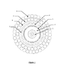
- Figure 1 shows a cross section of an embodiment of the cable of the present invention, and is not to scale.
- the first conductor 1 forms the central core of the cable.
- the cable may be formed of a plurality of wires (7 are schematically shown, although more may be used).
- the first conductor is surrounded by a first insulator layer 2.
- the first insulator layer is surrounded by a second conductor 3.
- the second conductor may be formed of a plurality of wires disposed around the first insulator layer to form, in effect, a layer of conductor.
- the second conductor is surrounded by a second insulator layer 4.
- the second insulator layer is surrounded by a barrier layer 5, which is surrounded by a jacket layer 6.
- Armour wires are provided on the outside of the cable - a first plurality 7 is disposed in a layer, which is surrounded by a second plurality of wires 8.
- This provides a cable having the following properties:
Landscapes
- Physics & Mathematics (AREA)
- Spectroscopy & Molecular Physics (AREA)
- Engineering & Computer Science (AREA)
- Manufacturing & Machinery (AREA)
- Insulated Conductors (AREA)
- Organic Insulating Materials (AREA)
- Addition Polymer Or Copolymer, Post-Treatments, Or Chemical Modifications (AREA)
Applications Claiming Priority (2)
| Application Number | Priority Date | Filing Date | Title |
|---|---|---|---|
| GBGB1216685.6A GB201216685D0 (en) | 2012-09-18 | 2012-09-18 | Subterranean cable |
| GBGB1223227.8A GB201223227D0 (en) | 2012-09-18 | 2012-12-20 | Subterranean cable |
Publications (2)
| Publication Number | Publication Date |
|---|---|
| EP2709113A1 true EP2709113A1 (fr) | 2014-03-19 |
| EP2709113B1 EP2709113B1 (fr) | 2017-11-22 |
Family
ID=47144483
Family Applications (2)
| Application Number | Title | Priority Date | Filing Date |
|---|---|---|---|
| EP13184916.8A Not-in-force EP2709113B1 (fr) | 2012-09-18 | 2013-09-18 | Câble sous-terrain |
| EP13184918.4A Not-in-force EP2709114B1 (fr) | 2012-09-18 | 2013-09-18 | Câble sous-terrain |
Family Applications After (1)
| Application Number | Title | Priority Date | Filing Date |
|---|---|---|---|
| EP13184918.4A Not-in-force EP2709114B1 (fr) | 2012-09-18 | 2013-09-18 | Câble sous-terrain |
Country Status (4)
| Country | Link |
|---|---|
| US (2) | US20140076597A1 (fr) |
| EP (2) | EP2709113B1 (fr) |
| GB (4) | GB201216685D0 (fr) |
| NO (2) | NO2709114T3 (fr) |
Cited By (6)
| Publication number | Priority date | Publication date | Assignee | Title |
|---|---|---|---|---|
| CN104751986A (zh) * | 2015-02-27 | 2015-07-01 | 安徽恒晶电缆集团有限公司 | 一种本质安全电路用电机屏蔽电缆 |
| CN105244093A (zh) * | 2015-10-30 | 2016-01-13 | 苏俊兰 | 耐磨低烟环保设备 |
| CN105405520A (zh) * | 2015-10-30 | 2016-03-16 | 苏俊兰 | 低烟环保设备 |
| CN107689266A (zh) * | 2017-07-07 | 2018-02-13 | 许亮 | 一种采油管缆及其制造装置 |
| WO2018228871A1 (fr) | 2017-06-14 | 2018-12-20 | Solvay Specialty Polymers Italy S.P.A. | Fluoropolymère ferroélectrique |
| WO2018228872A1 (fr) | 2017-06-14 | 2018-12-20 | Solvay Specialty Polymers Italy S.P.A. | Fluoropolymère piézoélectrique |
Families Citing this family (11)
| Publication number | Priority date | Publication date | Assignee | Title |
|---|---|---|---|---|
| NO340781B1 (no) * | 2013-11-18 | 2017-06-19 | Nexans | Kabel for nedihullspumpe |
| FR3020509B1 (fr) * | 2014-04-29 | 2016-05-13 | Axon Cable Sa | Contact electrique miniature de haute stabilite thermique |
| CN104715854A (zh) * | 2015-02-28 | 2015-06-17 | 安徽德源电缆集团有限公司 | 一种耐高温船舶屏蔽电力电缆 |
| US10036210B2 (en) * | 2015-05-01 | 2018-07-31 | Zilift Holdings, Ltd. | Method and system for deploying an electrical submersible pump in a wellbore |
| CN105719769B (zh) * | 2016-04-22 | 2017-10-03 | 安徽凌宇电缆科技有限公司 | 一种钪铝合金导体阻水中压电力电缆 |
| CN105869765A (zh) * | 2016-05-20 | 2016-08-17 | 安徽宏力特种线缆有限公司 | 一种阻水移动屏蔽电力软电缆 |
| CN105869767A (zh) * | 2016-05-20 | 2016-08-17 | 安徽宏力特种线缆有限公司 | 一种新型铝合金电力电缆 |
| CN105869766A (zh) * | 2016-05-20 | 2016-08-17 | 安徽宏力特种线缆有限公司 | 一种新型镍导体抗拉电力电缆 |
| CN106205810A (zh) * | 2016-08-31 | 2016-12-07 | 昆明三川电线电缆有限公司 | 一种具有共混弹性体绝缘及耐拖拽磨损的软电缆 |
| CN106971784A (zh) * | 2017-05-24 | 2017-07-21 | 苏州新区特氟龙塑料制品厂 | 一种抗腐蚀汽车电缆 |
| CN107017053B (zh) * | 2017-05-27 | 2023-04-25 | 特变电工(德阳)电缆股份有限公司 | 一种水密性防腐电力电缆及其制造方法 |
Citations (5)
| Publication number | Priority date | Publication date | Assignee | Title |
|---|---|---|---|---|
| EP0670577A1 (fr) * | 1994-01-18 | 1995-09-06 | Baker Hughes Incorporated | Isolation pour câble à base de polyéthylène réticulé |
| EP0930622A1 (fr) * | 1997-12-04 | 1999-07-21 | Camco International Inc. | Moteur submersible électrique avec protection interne contre la corrosion |
| EP0938101A2 (fr) * | 1998-02-21 | 1999-08-25 | Alcatel | Cordon électrique ou câble électrique |
| US20070158095A1 (en) * | 2006-01-11 | 2007-07-12 | Garud Sridhar | Lightweight armor wires for electrical cables |
| US20100147505A1 (en) * | 2008-12-11 | 2010-06-17 | Schlumberger Technology Corporation | Power cable for high temperature environments |
Family Cites Families (18)
| Publication number | Priority date | Publication date | Assignee | Title |
|---|---|---|---|---|
| GB920896A (en) * | 1960-10-18 | 1963-03-13 | Deutsche Edelstahlwerke Ag | A method of producing workpieces required to exhibit high strength at room and at elevated temperatures |
| US4634213A (en) * | 1983-04-11 | 1987-01-06 | Raychem Corporation | Connectors for power distribution cables |
| US5475185A (en) * | 1992-04-01 | 1995-12-12 | E. I. Du Pont De Nemours And Company | Shielded cable |
| DE4236560A1 (de) * | 1992-10-29 | 1994-05-05 | Kabelmetal Electro Gmbh | Kabel und Verfahren zur Herstellung eines Kabels |
| US5495547A (en) * | 1995-04-12 | 1996-02-27 | Western Atlas International, Inc. | Combination fiber-optic/electrical conductor well logging cable |
| US6600108B1 (en) * | 2002-01-25 | 2003-07-29 | Schlumberger Technology Corporation | Electric cable |
| US7009113B2 (en) * | 2003-01-22 | 2006-03-07 | Schlumberger Technology Corporation | High temperature electrical cable having interstitial filler |
| US20060065429A1 (en) * | 2004-09-28 | 2006-03-30 | Kim Byong J | Electrical cables |
| US7288721B2 (en) * | 2004-12-28 | 2007-10-30 | Schlumberger Technology Corporation | Electrical cables |
| US7170007B2 (en) * | 2005-01-12 | 2007-01-30 | Schlumburger Technology Corp. | Enhanced electrical cables |
| US7119283B1 (en) * | 2005-06-15 | 2006-10-10 | Schlumberger Technology Corp. | Enhanced armor wires for electrical cables |
| NO323516B1 (no) * | 2005-08-25 | 2007-06-04 | Nexans | Undervanns-kraftkabel og oppvarmingssystem |
| CA2568395C (fr) * | 2005-11-16 | 2010-03-30 | Service Wire Company | Connecteur et systeme de terminaison pour cable de commande de variateur de vitesse/a frequence variable |
| US7763802B2 (en) * | 2006-09-13 | 2010-07-27 | Schlumberger Technology Corporation | Electrical cable |
| US7541545B2 (en) * | 2006-11-30 | 2009-06-02 | Schlumberger Technology Corporation | Tapeless cable assembly and methods of manufacturing same |
| US8884163B2 (en) * | 2008-05-14 | 2014-11-11 | Nexans | Skin cured PTFE wire and cable |
| CA2790509A1 (fr) * | 2010-02-24 | 2011-09-01 | Joseph Varkey | Cable permanent pour pompes immergees dans des applications aux puits de petrole |
| US20130153260A1 (en) * | 2011-12-19 | 2013-06-20 | E I Du Pont De Nemours And Company | ESP Power Cables |
-
2012
- 2012-09-18 GB GBGB1216685.6A patent/GB201216685D0/en not_active Ceased
- 2012-12-20 GB GBGB1223227.8A patent/GB201223227D0/en not_active Ceased
-
2013
- 2013-09-18 NO NO13184918A patent/NO2709114T3/no unknown
- 2013-09-18 EP EP13184916.8A patent/EP2709113B1/fr not_active Not-in-force
- 2013-09-18 EP EP13184918.4A patent/EP2709114B1/fr not_active Not-in-force
- 2013-09-18 US US14/030,263 patent/US20140076597A1/en not_active Abandoned
- 2013-09-18 US US14/030,349 patent/US20140076606A1/en not_active Abandoned
- 2013-09-18 GB GB1316627.7A patent/GB2508695B/en not_active Expired - Fee Related
- 2013-09-18 NO NO13184916A patent/NO2709113T3/no unknown
- 2013-09-18 GB GB1316626.9A patent/GB2509804B/en not_active Expired - Fee Related
Patent Citations (5)
| Publication number | Priority date | Publication date | Assignee | Title |
|---|---|---|---|---|
| EP0670577A1 (fr) * | 1994-01-18 | 1995-09-06 | Baker Hughes Incorporated | Isolation pour câble à base de polyéthylène réticulé |
| EP0930622A1 (fr) * | 1997-12-04 | 1999-07-21 | Camco International Inc. | Moteur submersible électrique avec protection interne contre la corrosion |
| EP0938101A2 (fr) * | 1998-02-21 | 1999-08-25 | Alcatel | Cordon électrique ou câble électrique |
| US20070158095A1 (en) * | 2006-01-11 | 2007-07-12 | Garud Sridhar | Lightweight armor wires for electrical cables |
| US20100147505A1 (en) * | 2008-12-11 | 2010-06-17 | Schlumberger Technology Corporation | Power cable for high temperature environments |
Cited By (8)
| Publication number | Priority date | Publication date | Assignee | Title |
|---|---|---|---|---|
| CN104751986A (zh) * | 2015-02-27 | 2015-07-01 | 安徽恒晶电缆集团有限公司 | 一种本质安全电路用电机屏蔽电缆 |
| CN105244093A (zh) * | 2015-10-30 | 2016-01-13 | 苏俊兰 | 耐磨低烟环保设备 |
| CN105405520A (zh) * | 2015-10-30 | 2016-03-16 | 苏俊兰 | 低烟环保设备 |
| WO2018228871A1 (fr) | 2017-06-14 | 2018-12-20 | Solvay Specialty Polymers Italy S.P.A. | Fluoropolymère ferroélectrique |
| WO2018228872A1 (fr) | 2017-06-14 | 2018-12-20 | Solvay Specialty Polymers Italy S.P.A. | Fluoropolymère piézoélectrique |
| US11319387B2 (en) | 2017-06-14 | 2022-05-03 | Solvay Specialty Polymers Italy S.P.A. | Ferroelectric fluoropolymer |
| CN107689266A (zh) * | 2017-07-07 | 2018-02-13 | 许亮 | 一种采油管缆及其制造装置 |
| CN107689266B (zh) * | 2017-07-07 | 2019-03-15 | 许亮 | 一种采油管缆的制造装置 |
Also Published As
| Publication number | Publication date |
|---|---|
| NO2709113T3 (fr) | 2018-04-21 |
| EP2709113B1 (fr) | 2017-11-22 |
| GB2508695B (en) | 2015-02-11 |
| GB201316627D0 (en) | 2013-10-30 |
| EP2709114B1 (fr) | 2017-11-22 |
| GB2509804A (en) | 2014-07-16 |
| EP2709114A1 (fr) | 2014-03-19 |
| GB201216685D0 (en) | 2012-10-31 |
| US20140076597A1 (en) | 2014-03-20 |
| GB2509804B (en) | 2015-07-29 |
| NO2709114T3 (fr) | 2018-04-21 |
| US20140076606A1 (en) | 2014-03-20 |
| GB201316626D0 (en) | 2013-10-30 |
| GB2508695A (en) | 2014-06-11 |
| GB201223227D0 (en) | 2013-02-06 |
Similar Documents
| Publication | Publication Date | Title |
|---|---|---|
| EP2709113B1 (fr) | Câble sous-terrain | |
| US8113273B2 (en) | Power cable for high temperature environments | |
| EP3319091B1 (fr) | Câble de chauffage électrique direct superposable | |
| EP1998340A1 (fr) | Câble d'énergie électrique | |
| US20140102749A1 (en) | Electric Submersible Pump Cables for Harsh Environments | |
| AU2009275328B2 (en) | Umbilical | |
| CN106463207B (zh) | 具有强度元件的电力线缆 | |
| CA2790509A1 (fr) | Cable permanent pour pompes immergees dans des applications aux puits de petrole | |
| RU192508U1 (ru) | Электрический кабель для установок погружных электронасосов | |
| EP1064657A1 (fr) | Cable de manipulation conducteur | |
| NO349632B1 (en) | Power cables for electric submersible pump and systems and methods thereof | |
| EP3926645A1 (fr) | Câble ombilical pour le transport combiné de puissance et de fluide | |
| CN113614857A (zh) | 电力电缆及其制造方法和用途 | |
| NO20191434A1 (en) | Power cables for electric submersible pump | |
| CN106796828B (zh) | 深水传输用电线 | |
| WO2016148673A1 (fr) | Câble de puissance haute température résistant à la pénétration de fluides | |
| EP3057107B1 (fr) | Câble électrique à tube spiralé pour puits profonds | |
| HK40060134B (en) | Power cable, method for production and use thereof | |
| CN201820509U (zh) | 潜油电泵用圆-扁一体电力电缆 | |
| CA2307738A1 (fr) | Cable de pompe electrique submersible resistant a la corrosion pour utilisation dans des puits aux conditions extremes | |
| HK40060134A (en) | Power cable, method for production and use thereof | |
| OA19388A (en) | Power cables for electric submersible pump | |
| SK289223B6 (sk) | Trojfázový napájací kábel vrtného čerpadla |
Legal Events
| Date | Code | Title | Description |
|---|---|---|---|
| PUAI | Public reference made under article 153(3) epc to a published international application that has entered the european phase |
Free format text: ORIGINAL CODE: 0009012 |
|
| AK | Designated contracting states |
Kind code of ref document: A1 Designated state(s): AL AT BE BG CH CY CZ DE DK EE ES FI FR GB GR HR HU IE IS IT LI LT LU LV MC MK MT NL NO PL PT RO RS SE SI SK SM TR |
|
| AX | Request for extension of the european patent |
Extension state: BA ME |
|
| 17P | Request for examination filed |
Effective date: 20140826 |
|
| RBV | Designated contracting states (corrected) |
Designated state(s): AL AT BE BG CH CY CZ DE DK EE ES FI FR GB GR HR HU IE IS IT LI LT LU LV MC MK MT NL NO PL PT RO RS SE SI SK SM TR |
|
| GRAP | Despatch of communication of intention to grant a patent |
Free format text: ORIGINAL CODE: EPIDOSNIGR1 |
|
| STAA | Information on the status of an ep patent application or granted ep patent |
Free format text: STATUS: GRANT OF PATENT IS INTENDED |
|
| INTG | Intention to grant announced |
Effective date: 20170608 |
|
| GRAS | Grant fee paid |
Free format text: ORIGINAL CODE: EPIDOSNIGR3 |
|
| GRAJ | Information related to disapproval of communication of intention to grant by the applicant or resumption of examination proceedings by the epo deleted |
Free format text: ORIGINAL CODE: EPIDOSDIGR1 |
|
| GRAL | Information related to payment of fee for publishing/printing deleted |
Free format text: ORIGINAL CODE: EPIDOSDIGR3 |
|
| STAA | Information on the status of an ep patent application or granted ep patent |
Free format text: STATUS: REQUEST FOR EXAMINATION WAS MADE |
|
| GRAP | Despatch of communication of intention to grant a patent |
Free format text: ORIGINAL CODE: EPIDOSNIGR1 |
|
| STAA | Information on the status of an ep patent application or granted ep patent |
Free format text: STATUS: GRANT OF PATENT IS INTENDED |
|
| RBV | Designated contracting states (corrected) |
Designated state(s): AL AT BE BG CH CY CZ DE DK EE ES FI FR GR HR HU IE IS IT LI LT LU LV MC MK MT NL NO PL PT RO RS SE SI SK SM TR |
|
| INTC | Intention to grant announced (deleted) | ||
| INTG | Intention to grant announced |
Effective date: 20170922 |
|
| GRAA | (expected) grant |
Free format text: ORIGINAL CODE: 0009210 |
|
| STAA | Information on the status of an ep patent application or granted ep patent |
Free format text: STATUS: THE PATENT HAS BEEN GRANTED |
|
| AK | Designated contracting states |
Kind code of ref document: B1 Designated state(s): AL AT BE BG CH CY CZ DE DK EE ES FI FR GR HR HU IE IS IT LI LT LU LV MC MK MT NL NO PL PT RO RS SE SI SK SM TR |
|
| REG | Reference to a national code |
Ref country code: CH Ref legal event code: EP |
|
| REG | Reference to a national code |
Ref country code: IE Ref legal event code: FG4D |
|
| REG | Reference to a national code |
Ref country code: AT Ref legal event code: REF Ref document number: 949106 Country of ref document: AT Kind code of ref document: T Effective date: 20171215 |
|
| REG | Reference to a national code |
Ref country code: DE Ref legal event code: R096 Ref document number: 602013029700 Country of ref document: DE |
|
| REG | Reference to a national code |
Ref country code: NL Ref legal event code: FP |
|
| REG | Reference to a national code |
Ref country code: NO Ref legal event code: T2 Effective date: 20171122 |
|
| REG | Reference to a national code |
Ref country code: LT Ref legal event code: MG4D |
|
| REG | Reference to a national code |
Ref country code: AT Ref legal event code: MK05 Ref document number: 949106 Country of ref document: AT Kind code of ref document: T Effective date: 20171122 |
|
| PG25 | Lapsed in a contracting state [announced via postgrant information from national office to epo] |
Ref country code: ES Free format text: LAPSE BECAUSE OF FAILURE TO SUBMIT A TRANSLATION OF THE DESCRIPTION OR TO PAY THE FEE WITHIN THE PRESCRIBED TIME-LIMIT Effective date: 20171122 Ref country code: SE Free format text: LAPSE BECAUSE OF FAILURE TO SUBMIT A TRANSLATION OF THE DESCRIPTION OR TO PAY THE FEE WITHIN THE PRESCRIBED TIME-LIMIT Effective date: 20171122 Ref country code: FI Free format text: LAPSE BECAUSE OF FAILURE TO SUBMIT A TRANSLATION OF THE DESCRIPTION OR TO PAY THE FEE WITHIN THE PRESCRIBED TIME-LIMIT Effective date: 20171122 Ref country code: LT Free format text: LAPSE BECAUSE OF FAILURE TO SUBMIT A TRANSLATION OF THE DESCRIPTION OR TO PAY THE FEE WITHIN THE PRESCRIBED TIME-LIMIT Effective date: 20171122 |
|
| REG | Reference to a national code |
Ref country code: FR Ref legal event code: CA Effective date: 20180424 |
|
| PG25 | Lapsed in a contracting state [announced via postgrant information from national office to epo] |
Ref country code: AT Free format text: LAPSE BECAUSE OF FAILURE TO SUBMIT A TRANSLATION OF THE DESCRIPTION OR TO PAY THE FEE WITHIN THE PRESCRIBED TIME-LIMIT Effective date: 20171122 Ref country code: BG Free format text: LAPSE BECAUSE OF FAILURE TO SUBMIT A TRANSLATION OF THE DESCRIPTION OR TO PAY THE FEE WITHIN THE PRESCRIBED TIME-LIMIT Effective date: 20180222 Ref country code: GR Free format text: LAPSE BECAUSE OF FAILURE TO SUBMIT A TRANSLATION OF THE DESCRIPTION OR TO PAY THE FEE WITHIN THE PRESCRIBED TIME-LIMIT Effective date: 20180223 Ref country code: LV Free format text: LAPSE BECAUSE OF FAILURE TO SUBMIT A TRANSLATION OF THE DESCRIPTION OR TO PAY THE FEE WITHIN THE PRESCRIBED TIME-LIMIT Effective date: 20171122 Ref country code: HR Free format text: LAPSE BECAUSE OF FAILURE TO SUBMIT A TRANSLATION OF THE DESCRIPTION OR TO PAY THE FEE WITHIN THE PRESCRIBED TIME-LIMIT Effective date: 20171122 Ref country code: RS Free format text: LAPSE BECAUSE OF FAILURE TO SUBMIT A TRANSLATION OF THE DESCRIPTION OR TO PAY THE FEE WITHIN THE PRESCRIBED TIME-LIMIT Effective date: 20171122 |
|
| PG25 | Lapsed in a contracting state [announced via postgrant information from national office to epo] |
Ref country code: SK Free format text: LAPSE BECAUSE OF FAILURE TO SUBMIT A TRANSLATION OF THE DESCRIPTION OR TO PAY THE FEE WITHIN THE PRESCRIBED TIME-LIMIT Effective date: 20171122 Ref country code: CZ Free format text: LAPSE BECAUSE OF FAILURE TO SUBMIT A TRANSLATION OF THE DESCRIPTION OR TO PAY THE FEE WITHIN THE PRESCRIBED TIME-LIMIT Effective date: 20171122 Ref country code: DK Free format text: LAPSE BECAUSE OF FAILURE TO SUBMIT A TRANSLATION OF THE DESCRIPTION OR TO PAY THE FEE WITHIN THE PRESCRIBED TIME-LIMIT Effective date: 20171122 Ref country code: CY Free format text: LAPSE BECAUSE OF FAILURE TO SUBMIT A TRANSLATION OF THE DESCRIPTION OR TO PAY THE FEE WITHIN THE PRESCRIBED TIME-LIMIT Effective date: 20171122 Ref country code: EE Free format text: LAPSE BECAUSE OF FAILURE TO SUBMIT A TRANSLATION OF THE DESCRIPTION OR TO PAY THE FEE WITHIN THE PRESCRIBED TIME-LIMIT Effective date: 20171122 |
|
| REG | Reference to a national code |
Ref country code: FR Ref legal event code: PLFP Year of fee payment: 6 |
|
| REG | Reference to a national code |
Ref country code: DE Ref legal event code: R097 Ref document number: 602013029700 Country of ref document: DE |
|
| PG25 | Lapsed in a contracting state [announced via postgrant information from national office to epo] |
Ref country code: RO Free format text: LAPSE BECAUSE OF FAILURE TO SUBMIT A TRANSLATION OF THE DESCRIPTION OR TO PAY THE FEE WITHIN THE PRESCRIBED TIME-LIMIT Effective date: 20171122 Ref country code: PL Free format text: LAPSE BECAUSE OF FAILURE TO SUBMIT A TRANSLATION OF THE DESCRIPTION OR TO PAY THE FEE WITHIN THE PRESCRIBED TIME-LIMIT Effective date: 20171122 Ref country code: IT Free format text: LAPSE BECAUSE OF FAILURE TO SUBMIT A TRANSLATION OF THE DESCRIPTION OR TO PAY THE FEE WITHIN THE PRESCRIBED TIME-LIMIT Effective date: 20171122 Ref country code: SM Free format text: LAPSE BECAUSE OF FAILURE TO SUBMIT A TRANSLATION OF THE DESCRIPTION OR TO PAY THE FEE WITHIN THE PRESCRIBED TIME-LIMIT Effective date: 20171122 |
|
| PLBE | No opposition filed within time limit |
Free format text: ORIGINAL CODE: 0009261 |
|
| STAA | Information on the status of an ep patent application or granted ep patent |
Free format text: STATUS: NO OPPOSITION FILED WITHIN TIME LIMIT |
|
| 26N | No opposition filed |
Effective date: 20180823 |
|
| PG25 | Lapsed in a contracting state [announced via postgrant information from national office to epo] |
Ref country code: SI Free format text: LAPSE BECAUSE OF FAILURE TO SUBMIT A TRANSLATION OF THE DESCRIPTION OR TO PAY THE FEE WITHIN THE PRESCRIBED TIME-LIMIT Effective date: 20171122 |
|
| PG25 | Lapsed in a contracting state [announced via postgrant information from national office to epo] |
Ref country code: MC Free format text: LAPSE BECAUSE OF FAILURE TO SUBMIT A TRANSLATION OF THE DESCRIPTION OR TO PAY THE FEE WITHIN THE PRESCRIBED TIME-LIMIT Effective date: 20171122 |
|
| REG | Reference to a national code |
Ref country code: CH Ref legal event code: PL |
|
| REG | Reference to a national code |
Ref country code: BE Ref legal event code: MM Effective date: 20180930 |
|
| REG | Reference to a national code |
Ref country code: IE Ref legal event code: MM4A |
|
| PG25 | Lapsed in a contracting state [announced via postgrant information from national office to epo] |
Ref country code: LU Free format text: LAPSE BECAUSE OF NON-PAYMENT OF DUE FEES Effective date: 20180918 |
|
| PG25 | Lapsed in a contracting state [announced via postgrant information from national office to epo] |
Ref country code: IE Free format text: LAPSE BECAUSE OF NON-PAYMENT OF DUE FEES Effective date: 20180918 |
|
| PG25 | Lapsed in a contracting state [announced via postgrant information from national office to epo] |
Ref country code: BE Free format text: LAPSE BECAUSE OF NON-PAYMENT OF DUE FEES Effective date: 20180930 Ref country code: CH Free format text: LAPSE BECAUSE OF NON-PAYMENT OF DUE FEES Effective date: 20180930 Ref country code: LI Free format text: LAPSE BECAUSE OF NON-PAYMENT OF DUE FEES Effective date: 20180930 |
|
| PG25 | Lapsed in a contracting state [announced via postgrant information from national office to epo] |
Ref country code: MT Free format text: LAPSE BECAUSE OF NON-PAYMENT OF DUE FEES Effective date: 20180918 |
|
| PG25 | Lapsed in a contracting state [announced via postgrant information from national office to epo] |
Ref country code: TR Free format text: LAPSE BECAUSE OF FAILURE TO SUBMIT A TRANSLATION OF THE DESCRIPTION OR TO PAY THE FEE WITHIN THE PRESCRIBED TIME-LIMIT Effective date: 20171122 |
|
| PG25 | Lapsed in a contracting state [announced via postgrant information from national office to epo] |
Ref country code: HU Free format text: LAPSE BECAUSE OF FAILURE TO SUBMIT A TRANSLATION OF THE DESCRIPTION OR TO PAY THE FEE WITHIN THE PRESCRIBED TIME-LIMIT; INVALID AB INITIO Effective date: 20130918 Ref country code: PT Free format text: LAPSE BECAUSE OF FAILURE TO SUBMIT A TRANSLATION OF THE DESCRIPTION OR TO PAY THE FEE WITHIN THE PRESCRIBED TIME-LIMIT Effective date: 20171122 |
|
| PG25 | Lapsed in a contracting state [announced via postgrant information from national office to epo] |
Ref country code: MK Free format text: LAPSE BECAUSE OF NON-PAYMENT OF DUE FEES Effective date: 20171122 |
|
| PG25 | Lapsed in a contracting state [announced via postgrant information from national office to epo] |
Ref country code: AL Free format text: LAPSE BECAUSE OF FAILURE TO SUBMIT A TRANSLATION OF THE DESCRIPTION OR TO PAY THE FEE WITHIN THE PRESCRIBED TIME-LIMIT Effective date: 20171122 Ref country code: IS Free format text: LAPSE BECAUSE OF FAILURE TO SUBMIT A TRANSLATION OF THE DESCRIPTION OR TO PAY THE FEE WITHIN THE PRESCRIBED TIME-LIMIT Effective date: 20180322 |
|
| PGFP | Annual fee paid to national office [announced via postgrant information from national office to epo] |
Ref country code: DE Payment date: 20200909 Year of fee payment: 8 Ref country code: NL Payment date: 20200915 Year of fee payment: 8 Ref country code: NO Payment date: 20200910 Year of fee payment: 8 Ref country code: FR Payment date: 20200812 Year of fee payment: 8 |
|
| REG | Reference to a national code |
Ref country code: DE Ref legal event code: R119 Ref document number: 602013029700 Country of ref document: DE |
|
| REG | Reference to a national code |
Ref country code: NO Ref legal event code: MMEP |
|
| REG | Reference to a national code |
Ref country code: NL Ref legal event code: MM Effective date: 20211001 |
|
| PG25 | Lapsed in a contracting state [announced via postgrant information from national office to epo] |
Ref country code: NL Free format text: LAPSE BECAUSE OF NON-PAYMENT OF DUE FEES Effective date: 20211001 |
|
| PG25 | Lapsed in a contracting state [announced via postgrant information from national office to epo] |
Ref country code: NO Free format text: LAPSE BECAUSE OF NON-PAYMENT OF DUE FEES Effective date: 20210930 Ref country code: FR Free format text: LAPSE BECAUSE OF NON-PAYMENT OF DUE FEES Effective date: 20210930 Ref country code: DE Free format text: LAPSE BECAUSE OF NON-PAYMENT OF DUE FEES Effective date: 20220401 |