EP2709191A1 - Soupape de sécurité et élément électrochimique - Google Patents
Soupape de sécurité et élément électrochimique Download PDFInfo
- Publication number
- EP2709191A1 EP2709191A1 EP13768899.0A EP13768899A EP2709191A1 EP 2709191 A1 EP2709191 A1 EP 2709191A1 EP 13768899 A EP13768899 A EP 13768899A EP 2709191 A1 EP2709191 A1 EP 2709191A1
- Authority
- EP
- European Patent Office
- Prior art keywords
- gas
- vent
- safety vent
- exterior casing
- out port
- Prior art date
- Legal status (The legal status is an assumption and is not a legal conclusion. Google has not performed a legal analysis and makes no representation as to the accuracy of the status listed.)
- Withdrawn
Links
Images









Classifications
-
- H—ELECTRICITY
- H01—ELECTRIC ELEMENTS
- H01M—PROCESSES OR MEANS, e.g. BATTERIES, FOR THE DIRECT CONVERSION OF CHEMICAL ENERGY INTO ELECTRICAL ENERGY
- H01M50/00—Constructional details or processes of manufacture of the non-active parts of electrochemical cells other than fuel cells, e.g. hybrid cells
- H01M50/10—Primary casings; Jackets or wrappings
- H01M50/116—Primary casings; Jackets or wrappings characterised by the material
- H01M50/124—Primary casings; Jackets or wrappings characterised by the material having a layered structure
-
- H—ELECTRICITY
- H01—ELECTRIC ELEMENTS
- H01M—PROCESSES OR MEANS, e.g. BATTERIES, FOR THE DIRECT CONVERSION OF CHEMICAL ENERGY INTO ELECTRICAL ENERGY
- H01M50/00—Constructional details or processes of manufacture of the non-active parts of electrochemical cells other than fuel cells, e.g. hybrid cells
- H01M50/30—Arrangements for facilitating escape of gases
-
- H—ELECTRICITY
- H01—ELECTRIC ELEMENTS
- H01M—PROCESSES OR MEANS, e.g. BATTERIES, FOR THE DIRECT CONVERSION OF CHEMICAL ENERGY INTO ELECTRICAL ENERGY
- H01M50/00—Constructional details or processes of manufacture of the non-active parts of electrochemical cells other than fuel cells, e.g. hybrid cells
- H01M50/30—Arrangements for facilitating escape of gases
- H01M50/317—Re-sealable arrangements
-
- H—ELECTRICITY
- H01—ELECTRIC ELEMENTS
- H01G—CAPACITORS; CAPACITORS, RECTIFIERS, DETECTORS, SWITCHING DEVICES, LIGHT-SENSITIVE OR TEMPERATURE-SENSITIVE DEVICES OF THE ELECTROLYTIC TYPE
- H01G11/00—Hybrid capacitors, i.e. capacitors having different positive and negative electrodes; Electric double-layer [EDL] capacitors; Processes for the manufacture thereof or of parts thereof
-
- H—ELECTRICITY
- H01—ELECTRIC ELEMENTS
- H01G—CAPACITORS; CAPACITORS, RECTIFIERS, DETECTORS, SWITCHING DEVICES, LIGHT-SENSITIVE OR TEMPERATURE-SENSITIVE DEVICES OF THE ELECTROLYTIC TYPE
- H01G11/00—Hybrid capacitors, i.e. capacitors having different positive and negative electrodes; Electric double-layer [EDL] capacitors; Processes for the manufacture thereof or of parts thereof
- H01G11/14—Arrangements or processes for adjusting or protecting hybrid or EDL capacitors
-
- H—ELECTRICITY
- H01—ELECTRIC ELEMENTS
- H01G—CAPACITORS; CAPACITORS, RECTIFIERS, DETECTORS, SWITCHING DEVICES, LIGHT-SENSITIVE OR TEMPERATURE-SENSITIVE DEVICES OF THE ELECTROLYTIC TYPE
- H01G11/00—Hybrid capacitors, i.e. capacitors having different positive and negative electrodes; Electric double-layer [EDL] capacitors; Processes for the manufacture thereof or of parts thereof
- H01G11/14—Arrangements or processes for adjusting or protecting hybrid or EDL capacitors
- H01G11/18—Arrangements or processes for adjusting or protecting hybrid or EDL capacitors against thermal overloads, e.g. heating, cooling or ventilating
-
- H—ELECTRICITY
- H01—ELECTRIC ELEMENTS
- H01G—CAPACITORS; CAPACITORS, RECTIFIERS, DETECTORS, SWITCHING DEVICES, LIGHT-SENSITIVE OR TEMPERATURE-SENSITIVE DEVICES OF THE ELECTROLYTIC TYPE
- H01G11/00—Hybrid capacitors, i.e. capacitors having different positive and negative electrodes; Electric double-layer [EDL] capacitors; Processes for the manufacture thereof or of parts thereof
- H01G11/78—Cases; Housings; Encapsulations; Mountings
-
- H—ELECTRICITY
- H01—ELECTRIC ELEMENTS
- H01M—PROCESSES OR MEANS, e.g. BATTERIES, FOR THE DIRECT CONVERSION OF CHEMICAL ENERGY INTO ELECTRICAL ENERGY
- H01M10/00—Secondary cells; Manufacture thereof
- H01M10/05—Accumulators with non-aqueous electrolyte
- H01M10/052—Li-accumulators
- H01M10/0525—Rocking-chair batteries, i.e. batteries with lithium insertion or intercalation in both electrodes; Lithium-ion batteries
-
- H—ELECTRICITY
- H01—ELECTRIC ELEMENTS
- H01M—PROCESSES OR MEANS, e.g. BATTERIES, FOR THE DIRECT CONVERSION OF CHEMICAL ENERGY INTO ELECTRICAL ENERGY
- H01M50/00—Constructional details or processes of manufacture of the non-active parts of electrochemical cells other than fuel cells, e.g. hybrid cells
- H01M50/10—Primary casings; Jackets or wrappings
- H01M50/102—Primary casings; Jackets or wrappings characterised by their shape or physical structure
- H01M50/105—Pouches or flexible bags
-
- H—ELECTRICITY
- H01—ELECTRIC ELEMENTS
- H01M—PROCESSES OR MEANS, e.g. BATTERIES, FOR THE DIRECT CONVERSION OF CHEMICAL ENERGY INTO ELECTRICAL ENERGY
- H01M50/00—Constructional details or processes of manufacture of the non-active parts of electrochemical cells other than fuel cells, e.g. hybrid cells
- H01M50/10—Primary casings; Jackets or wrappings
- H01M50/147—Lids or covers
-
- H—ELECTRICITY
- H01—ELECTRIC ELEMENTS
- H01M—PROCESSES OR MEANS, e.g. BATTERIES, FOR THE DIRECT CONVERSION OF CHEMICAL ENERGY INTO ELECTRICAL ENERGY
- H01M50/00—Constructional details or processes of manufacture of the non-active parts of electrochemical cells other than fuel cells, e.g. hybrid cells
- H01M50/10—Primary casings; Jackets or wrappings
- H01M50/172—Arrangements of electric connectors penetrating the casing
- H01M50/174—Arrangements of electric connectors penetrating the casing adapted for the shape of the cells
- H01M50/178—Arrangements of electric connectors penetrating the casing adapted for the shape of the cells for pouch or flexible bag cells
-
- H—ELECTRICITY
- H01—ELECTRIC ELEMENTS
- H01M—PROCESSES OR MEANS, e.g. BATTERIES, FOR THE DIRECT CONVERSION OF CHEMICAL ENERGY INTO ELECTRICAL ENERGY
- H01M50/00—Constructional details or processes of manufacture of the non-active parts of electrochemical cells other than fuel cells, e.g. hybrid cells
- H01M50/30—Arrangements for facilitating escape of gases
- H01M50/317—Re-sealable arrangements
- H01M50/325—Re-sealable arrangements comprising deformable valve members, e.g. elastic or flexible valve members
-
- H—ELECTRICITY
- H01—ELECTRIC ELEMENTS
- H01M—PROCESSES OR MEANS, e.g. BATTERIES, FOR THE DIRECT CONVERSION OF CHEMICAL ENERGY INTO ELECTRICAL ENERGY
- H01M50/00—Constructional details or processes of manufacture of the non-active parts of electrochemical cells other than fuel cells, e.g. hybrid cells
- H01M50/30—Arrangements for facilitating escape of gases
- H01M50/317—Re-sealable arrangements
- H01M50/325—Re-sealable arrangements comprising deformable valve members, e.g. elastic or flexible valve members
- H01M50/333—Spring-loaded vent valves
-
- H—ELECTRICITY
- H01—ELECTRIC ELEMENTS
- H01M—PROCESSES OR MEANS, e.g. BATTERIES, FOR THE DIRECT CONVERSION OF CHEMICAL ENERGY INTO ELECTRICAL ENERGY
- H01M50/00—Constructional details or processes of manufacture of the non-active parts of electrochemical cells other than fuel cells, e.g. hybrid cells
- H01M50/30—Arrangements for facilitating escape of gases
- H01M50/342—Non-re-sealable arrangements
- H01M50/3425—Non-re-sealable arrangements in the form of rupturable membranes or weakened parts, e.g. pierced with the aid of a sharp member
-
- H—ELECTRICITY
- H01—ELECTRIC ELEMENTS
- H01M—PROCESSES OR MEANS, e.g. BATTERIES, FOR THE DIRECT CONVERSION OF CHEMICAL ENERGY INTO ELECTRICAL ENERGY
- H01M50/00—Constructional details or processes of manufacture of the non-active parts of electrochemical cells other than fuel cells, e.g. hybrid cells
- H01M50/30—Arrangements for facilitating escape of gases
- H01M50/35—Gas exhaust passages comprising elongated, tortuous or labyrinth-shaped exhaust passages
- H01M50/367—Internal gas exhaust passages forming part of the battery cover or case; Double cover vent systems
-
- H—ELECTRICITY
- H01—ELECTRIC ELEMENTS
- H01M—PROCESSES OR MEANS, e.g. BATTERIES, FOR THE DIRECT CONVERSION OF CHEMICAL ENERGY INTO ELECTRICAL ENERGY
- H01M50/00—Constructional details or processes of manufacture of the non-active parts of electrochemical cells other than fuel cells, e.g. hybrid cells
- H01M50/30—Arrangements for facilitating escape of gases
- H01M50/394—Gas-pervious parts or elements
-
- H—ELECTRICITY
- H01—ELECTRIC ELEMENTS
- H01M—PROCESSES OR MEANS, e.g. BATTERIES, FOR THE DIRECT CONVERSION OF CHEMICAL ENERGY INTO ELECTRICAL ENERGY
- H01M50/00—Constructional details or processes of manufacture of the non-active parts of electrochemical cells other than fuel cells, e.g. hybrid cells
- H01M50/50—Current conducting connections for cells or batteries
- H01M50/543—Terminals
- H01M50/552—Terminals characterised by their shape
- H01M50/553—Terminals adapted for prismatic, pouch or rectangular cells
- H01M50/557—Plate-shaped terminals
-
- H—ELECTRICITY
- H01—ELECTRIC ELEMENTS
- H01M—PROCESSES OR MEANS, e.g. BATTERIES, FOR THE DIRECT CONVERSION OF CHEMICAL ENERGY INTO ELECTRICAL ENERGY
- H01M50/00—Constructional details or processes of manufacture of the non-active parts of electrochemical cells other than fuel cells, e.g. hybrid cells
- H01M50/50—Current conducting connections for cells or batteries
- H01M50/543—Terminals
- H01M50/547—Terminals characterised by the disposition of the terminals on the cells
- H01M50/55—Terminals characterised by the disposition of the terminals on the cells on the same side of the cell
-
- Y—GENERAL TAGGING OF NEW TECHNOLOGICAL DEVELOPMENTS; GENERAL TAGGING OF CROSS-SECTIONAL TECHNOLOGIES SPANNING OVER SEVERAL SECTIONS OF THE IPC; TECHNICAL SUBJECTS COVERED BY FORMER USPC CROSS-REFERENCE ART COLLECTIONS [XRACs] AND DIGESTS
- Y02—TECHNOLOGIES OR APPLICATIONS FOR MITIGATION OR ADAPTATION AGAINST CLIMATE CHANGE
- Y02E—REDUCTION OF GREENHOUSE GAS [GHG] EMISSIONS, RELATED TO ENERGY GENERATION, TRANSMISSION OR DISTRIBUTION
- Y02E60/00—Enabling technologies; Technologies with a potential or indirect contribution to GHG emissions mitigation
- Y02E60/10—Energy storage using batteries
-
- Y—GENERAL TAGGING OF NEW TECHNOLOGICAL DEVELOPMENTS; GENERAL TAGGING OF CROSS-SECTIONAL TECHNOLOGIES SPANNING OVER SEVERAL SECTIONS OF THE IPC; TECHNICAL SUBJECTS COVERED BY FORMER USPC CROSS-REFERENCE ART COLLECTIONS [XRACs] AND DIGESTS
- Y02—TECHNOLOGIES OR APPLICATIONS FOR MITIGATION OR ADAPTATION AGAINST CLIMATE CHANGE
- Y02E—REDUCTION OF GREENHOUSE GAS [GHG] EMISSIONS, RELATED TO ENERGY GENERATION, TRANSMISSION OR DISTRIBUTION
- Y02E60/00—Enabling technologies; Technologies with a potential or indirect contribution to GHG emissions mitigation
- Y02E60/13—Energy storage using capacitors
-
- Y—GENERAL TAGGING OF NEW TECHNOLOGICAL DEVELOPMENTS; GENERAL TAGGING OF CROSS-SECTIONAL TECHNOLOGIES SPANNING OVER SEVERAL SECTIONS OF THE IPC; TECHNICAL SUBJECTS COVERED BY FORMER USPC CROSS-REFERENCE ART COLLECTIONS [XRACs] AND DIGESTS
- Y02—TECHNOLOGIES OR APPLICATIONS FOR MITIGATION OR ADAPTATION AGAINST CLIMATE CHANGE
- Y02T—CLIMATE CHANGE MITIGATION TECHNOLOGIES RELATED TO TRANSPORTATION
- Y02T10/00—Road transport of goods or passengers
- Y02T10/60—Other road transportation technologies with climate change mitigation effect
- Y02T10/70—Energy storage systems for electromobility, e.g. batteries
Definitions
- the present invention relates to a safety vent, and in particular relates to an optimal self-retum type safety vent for application to electrochemical devices such as secondary batteries, for example lithium secondary batteries and nickel-metal hydride secondary batteries, and to capacitors such as electrolytic capacitors, electric double layer capacitors, and lithium ion capacitors, and to an electrochemical device provided with said safety vent.
- electrochemical devices such as secondary batteries, for example lithium secondary batteries and nickel-metal hydride secondary batteries
- capacitors such as electrolytic capacitors, electric double layer capacitors, and lithium ion capacitors
- lithium ion batteries are being widely applied not only for comparatively low power purposes such as in mobile telephones and smartphones, but also for medium power to high power purposes such as electric cars, electric buses, hybrid electric vehicles (HEV), and a backup for fuel cell vehicles.
- plug-in hybrid vehicles (PEV) came into use, these PEVs employing medium to large size lithium ion batteries.
- large size electric double layer capacitors came into practice as a power source for rapid heating of heating drums in high-speed commercial copiers.
- laminated exterior casing type electrochemical devices as lithium ion battery for HEVs and PEVs and medium size to large size electrochemical devices such as large size electric double layer capacitors are paying attention from said prospect of weight and cost reduction.
- laminate type electrochemical devices are low in strength with respect to internal pressure, and there is a need to provide a safety vent in order to release gas generated inside.
- an object of the present invention is to provide an superior safety vent for attachment to a gas spout out port of an exterior casing in an electrochemical device, and particularly in an electrochemical device provided with a laminated exterior casing, and also to provide an electrochemical device in which said safety vent is attached to a gas spout out port of an exterior casing thereof.
- a first aspect of the present invention relates to a safety vent and is characterized in including: a gas permeated membrane through which gas generated inside an electrochemical device permeates; a vent that opens when pressure inside said electrochemical device has exceeded a predetermined target pressure, and allows said gas to release to the outside of said electrochemical device through said gas permeated membrane; and a housing case that internally houses said vent and said gas permeated membrane, and that is attached to a gas spout out port formed in an exterior casing of said electrochemical device.
- said vent body overcomes said pressing force of said spring means to move away from a vent seat, and the gas releases through a gas release hole.
- said present safety vent gas accordingly releases when the gas pressure inside said exterior casing exceeds a target value.
- Said safety vent is moreover provided with said housing case that houses said vent body and said gas permeated membrane. Since said housing case is attached to said gas spout out port of said exterior casing of said electrochemical device, said safety vent can accordingly be easily attached to said exterior casing of said electrochemical device, and in particular can be firmly attached even when said exterior casing is a laminated exterior casing that is low in strength.
- a second aspect of the present invention is the safety vent of the first aspect, wherein said housing case is directly fixed to said gas spout out port of said exterior casing.
- a member for attaching said housing case to said gas spout out port is not required since said housing case is directly fixed to said gas spout out port of said exterior casing of said electrochemical device.
- the structure can accordingly be simplified in comparison to an embodiment having a configuration including a member for attaching said housing case to said gas spout out port.
- a third aspect of the present invention is the safety vent of the first aspect, further including: an empty case that is empty inside, and that is fixed to said gas spout out port of said empty exterior casing, wherein said housing case is attached to said gas spout out port with said empty case interposed therebetween.
- Said safety vent is attached to said gas spout out port of said exterior casing with said empty case interposed therebetween. Said safety vent can accordingly be even more easily and securely attached to said gas spout out port of said safety vent in comparison to cases in which said safety vent is directly fixed to said gas spout out port of said exterior casing.
- a fourth aspect of the present invention is the safety vent of the third aspect, wherein said empty case includes: a first empty case that is joined to said housing case; and a second empty case that is fixed to said gas spout out port of said exterior casing, and to which said first empty case is joined.
- said safety vent can be attached to said gas spout out port of said exterior casing by attaching said second empty case to said gas spout out port of said exterior casing in advance, and then attaching said safety vent to said gas spout out port of said exterior casing by joining together said first empty case and said second empty case.
- Said safety vent can accordingly be attached to said gas spout out port more easily than when said empty case is not split into said first empty case and said second empty case.
- a fifth aspect of the present invention is the safety vent of any one of the first aspect to the fourth aspect, wherein: said vent includes a vent seat formed with a gas release hole, a vent body, and a spring means that presses said vent body against said gas release hole of said vent seat; said spring means is a plane spring including a base portion formed in a plane frame shape, and a load bearing portion that is resiliently supported through plural spring element portions on said in-plane direction inside of said base portion, wherein said vent body is pressed against said gas release hole by said load bearing portion of said plane spring.
- said vent body is configured so as to be pressed against said gas release hole by said load bearing portion of said plane spring. Said dimension along said overlapping direction of said vent body and said spring means can accordingly be made smaller.
- a sixth aspect of the present invention is the safety vent of any one of the first aspect to the fifth aspect, wherein said gas permeated membrane is formed from a nonwoven fabric or a woven fabric, said nonwoven fabric or woven fabric configured by spun fibers of a polyvinylidene fluoride resin and a polyacrylonitrile resin.
- said gas permeated membrane is formed from a nonwoven fabric or a woven fabric configured by spun fibers of a polyvinylidene fluoride resin and a polyacrylonitrile resin. Said gas permeated membrane accordingly has a high mechanical strength and capability of withstanding long term use. Moreover, electrolyte in said various gases generated inside said electrochemical device can be left inside said electrochemical device, with only byproduct gas being allowed to release to the outside.
- a seventh aspect of the present invention is the safety vent of the sixth aspect, wherein said gas permeated membrane is a compound film provided with a fluororesin layer on one face or on both faces of said nonwoven fabric or woven fabric of said seventh aspect.
- said gas permeated membrane is configured by said compound film provided with a fluororesin layer on one face or on both faces of said nonwoven fabric or said woven fabric of said seventh aspect. Said gas permeated membrane accordingly has a higher mechanical strength, and is even better at withstanding long term use, than when said gas permeated membrane is configured from said nonwoven fabric or said woven fabric of said seventh aspect alone.
- An eighth aspect of the present invention is the safety vent of either the sixth aspect or the seventh aspect, wherein said gas permeated membrane has a thickness of from 15 ⁇ m to 60 ⁇ m.
- the mechanical strength of said gas permeated membrane can be maintained, and there is a low resistance to gas permeation during gas release due to configuring said gas permeated membrane with a thickness of from 15 ⁇ m to 60 ⁇ m.
- a ninth aspect of the present invention is the safety vent of any one of the sixth aspect to the eighth aspect, wherein said gas permeated membrane has a fiber diameter of from 0.1 ⁇ m to 0.6 ⁇ m, and a pore diameter of from 0.25 ⁇ m to 0.35 ⁇ m.
- the mechanical strength of said gas permeated membrane is maintained and resistance to gas permeation is reduced, thereby securing gas release speed, due to configuring said gas permeated membrane with a fiber diameter of from 0.1 ⁇ m to 0.6 ⁇ m and a pore diameter of from 0.25 ⁇ m to 0.35 ⁇ m.
- a tenth aspect of the present invention is an electrochemical device including: an exterior casing formed with a gas spout out port, wherein the safety vent of any one of the first aspect to the ninth aspect is attached to said gas spout out port of said exterior casing.
- An eleventh aspect of the present invention is the electrochemical device of the tenth aspect, wherein said exterior casing is a laminate type exterior casing.
- the present invention provides an superior safety vent for attachment to a gas spout out port of an exterior casing in an electrochemical device, and also provides an electrochemical device in which said safety vent is attached to a gas spout out port of an exterior casing thereof.
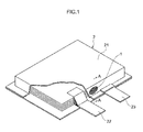
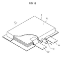
- a safety vent 1 of the first exemplary embodiment is a self-retum type safety vent including a vent 3 that allows gas generated inside a laminate type battery 2 that is an electrochemical device to release to the outside, and a gas permeated membrane 4 through which the gas permeates.
- the safety vent 1 includes a housing case 5 that houses the vent 3 and the gas permeated membrane 4.
- the housing case 5 has a bottomed circular cylinder shape with a lower height compared to the diameter thereof.
- the housing case 5 includes a circular cylinder shaped main body 54, a bottom face 51 formed at one end of the main body 54, an opening portion 50 formed at an opposite side end portion of the main body 54 to the side formed with the bottom face 51, and a flange portion 52 extending from the opening portion 50 side end portion towards outside along the main body 54 radial direction.
- the bottom face 51 of the housing case 5 is formed with a bottom face opening portion 53.
- a laminated exterior casing 21 of the laminate type battery 2 is formed with a gas spout out port 24 that spouts out byproduct gas.
- the overall housing case 5 is positioned inside of the laminated exterior casing 21, and the housing case 5 is fixed at the flange portion 52 to an inside face of the laminated exterior casing 21 using an adhesive 6 at the position formed with the gas spout out port 24.
- the safety vent 1 is obviously also positioned between the negative terminal 22 and the positive terminal 23.
- the vent 3 includes a vent seat 32 formed with a gas release hole 33 that allows gas generated inside the laminate type battery 2 to release, a spherical shaped vent body 34 that closes the gas release hole 33, and a planar spring 31 that is positioned on the opposite side of the vent body 34 to the vent seat 32 and presses the vent body 34 against the vent seat 32 to shut off the gas release hole 33.
- a gasket 35 is provided between the vent seat 32 and the plane spring 31.
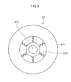
- the planar spring 31 includes a base portion 311 formed in a planar frame shape, and a load bearing portion 313 that is resiliently supported on the in-plane direction inside of the base portion 311 through plural spring element portions 312.
- the base portion 311, the spring element portions 312, and the load bearing portion 313 are formed integrally to each other in the planar spring 31.
- the vent body 34 is pressed against the gas release hole 33 of the vent seat 32 at the load bearing portion 313.
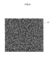
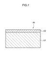
- the gas permeated membrane 4 employs a compound film 43 that includes fluororesin layers 42 formed on both faces of a base cloth 41 that is a nonwoven fabric or woven fabric configured by fibers of a polyvinylidene fluoride resin and a polyacrylonitrile resin.
- the fluororesin layers 42 are formed by applying or coating a fluororesin such as a polyvinylidene fluoride resin to both faces of the base cloth 41.
- the gas permeated membrane 4 also employs a compound film 44 formed with a fluororesin layer 42 on one face of the base cloth 41.
- Fluororesins employed in the fluororesin layers 42 may include for example tetrafluoroethylene/ hexafluoropropylene polymers, polytetrafluoroethylene resins, and polyvinyl fluoride resins as well as polyvinylidene fluoride resin.
- the base cloth 41 alone may be employed as a gas permeated membrane 4 without any problem, in order to withstand long term use, configuration is preferably made with the compound film 43 in which the fluororesin layers 42 are formed on both faces of the base cloth 41, or with the compound film 44 in which the fluororesin layer 42 is formed on one face of the base cloth 41.
- the layer thickness of the gas permeated membrane 4 is preferably from 15 ⁇ m to 60 ⁇ m. When the layer thickness is less than 15 ⁇ m, the gas permeated membrane 4 has insufficient mechanical strength, and there is a possibility of damage occurring due to the pressure of gas being expelled from the safety vent 1. While, when the layer thickness exceeds 60 ⁇ m the resistance to gas permeation becomes too large.
- the thickness of the fluororesin layer 42 is preferably from 0.5 ⁇ m to 5 ⁇ m.
- the thickness of the fluororesin layer 42 is less than 0.5 ⁇ m there is a possibility that the gas permeated membrane 4 obtained may not be able to withstand long term use, and when the thickness of the fluororesin layer 42 exceeds 5 ⁇ m, there is a concern of the resistance to gas permeation becoming too large in the gas permeated membrane 4 that is obtained.
- the base cloth 41 for example, a nonwoven fabric or a woven fabric, which is configured by fibers that are electro-spun employing a spinning solution prepared by dissolving a polyvinylidene fluoride resin and a polyacrylonitrile resin in a solvent as appropriate, can be employed.
- the proportion of polyvinylidene fluoride resin in the fiber configuring the base cloth 41 is preferably within a range of 30% by weight to 70% by weight. When the proportion of polyvinylidene fluoride resin in the fiber is less than 30% by weight, there are issues with poor heat resistance. On the other hand, it is not desirable for the proportion of polyvinylidene fluoride resin to exceed 70% by weight from the perspectives of softness and flexibility.
- the fiber diameter is preferably 0.1 ⁇ m or above, and is particularly preferably within a range of 0.1 ⁇ m to 0.6 ⁇ m. Not only are electro-spinning nozzles for the manufacture of fiber diameters of below 0.1 ⁇ m costly, but there is a possibility of the fibers obtained being too fine, such that sufficient strength cannot be obtained for the gas permeated membrane 4.
- the gas permeated membrane 4 preferably has a pore diameter of from 0.25 ⁇ m to 0.3 ⁇ m. When the pore diameter is below 0.25 ⁇ m the gas permeation rate is too slow, while when the pore diameter exceeds 0.3 ⁇ m it is difficult to separate the electrolyte from the byproduct gas in the gas generated inside the laminate type battery 2.
- the gas permeated membrane 4 may also be formed from polyvinylidene fluoride resin alone.
- the layer thickness of the gas permeated membrane 4 formed of polyvinylidene fluoride resin alone is preferably from 10 ⁇ m to 30 ⁇ m, at this thickness, films configured from polyvinylidene fluoride resin alone lack sufficient mechanical strength, and thus, the film can be damaged due to the pressure of gas being expelled from the safety vent 1.
- the vent body 34 receives force in a direction to push the vent body 34 toward the outside of the laminate type battery 2 due to the pressure of the gas inside the laminated exterior casing 21.
- the load bearing portion 313 of the plane spring 31 is accordingly pushed toward the outside of the laminate type battery 2 by the vent body 34, and the spring element portions 312 extend.
- the vent body 34 accordingly moves away from the gas release hole 33 of the vent seat 32, thereby opening the gas release hole 33, and gas inside the laminate type battery 2 passes through the gas permeated membrane 4 and releases to the outside. Gas continues to release until the gas pressure inside the laminate type battery 2 returns to a normal range.
- the gas permeated membrane 4 employs the fluororesin layers 42 formed on one face or both faces of a nonwoven fabric or a woven fabric obtained by electro-spinning a polyvinylidene fluoride resin and a polyacrylonitrile resin. Accordingly, during release of gas generated inside the laminate type battery 2, electrolyte contained in the gas remains inside the laminate type battery, and only byproduct gas is able to release to the outside.
- the safety vent 1 is moreover attached to the gas spout out port 24 inside the laminated exterior casing 21 in a state in which the vent 3 and the gas permeated membrane 4 are housed in an integrated together state in the housing case 5.
- the safety vent 1 can accordingly be easily and firmly attached to the laminated exterior casing 21 that is low in strength.
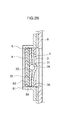
- a safety vent 1 of a second exemplary embodiment is self-retum type safety vent including a vent 3 that allows gas generated inside a laminate type battery 2 to release to the outside, and a gas permeated membrane 4 through which the gas permeates.
- a vent 3 that allows gas generated inside a laminate type battery 2 to release to the outside
- a gas permeated membrane 4 through which the gas permeates.
- a housing case 5 in the safety vent 1 of the second exemplary embodiment, includes an opening portion 50, a bottom face 51, a flange portion 52, a bottom face opening portion 53 and a main body 54, however the housing case 5 faces in the opposite direction to that of the safety vent 1 of the first exemplary embodiment.
- the main body 54 and the bottom face 51 are attached in a direction projecting from the gas spout out port 24 of the laminated exterior casing 21 towards the laminated exterior casing 21 outside, and the flange portion 52 is fixed using the adhesive 6 at the portion of the inside face of the laminated exterior casing 21 where the gas spout out port 24 is formed.
- the gas permeated membrane 4 is moreover housed on the opening portion 50 side of the vent seat 32.
- the plane spring 31, the vent body 34, the gasket 35 and the gas permeated membrane 4 are fixed inside the housing case 5 using the ring shaped spring form fixing portion 36.
- the porous metallic foil body 37 is adhered and fixed to an outside face of the bottom face 53 of the housing case 5.
- the porous metallic foil body 37 protects the safety vent 1 from mechanical shock and contamination from the outside.
- the safety vent 1 of the second exemplary embodiment is similar to the safety vent 1 of the first exemplary embodiment in the points other than those described above. Accordingly the configuration of the plane spring 31, the vent body 34, the gasket 35, the vent seat 32 and the gas permeated membrane 4 is as described in the first exemplary embodiment. Operation of the safety vent 1 is moreover as described in the first exemplary embodiment.
- the safety vent 1 of the second exemplary embodiment is attached to the gas spout out port 24 portion of the inside face of the laminated exterior casing 21 at a flange portion in a state in which the vent 3 and the gas permeated membrane 4 are housed in an integrated together state in the housing case 5.
- the safety vent 1 can accordingly be easily and firmly attached to the laminated exterior casing 21 that is low in strength.
- the housing case 5 is moreover fixed to the inside face of the laminated exterior casing 21 at the flange portion 52 such that the main body 54 and the bottom face 51 project out through the gas spout out port 24 to the laminated exterior casing 21 outside.
- the overall safety vent 1 is thereby effectively prevented from falling off to the inside of the laminate type battery 2 even when the adhesive 6 deteriorates and the adhesion force with respect to the laminated exterior casing 21 decreases.
- a safety vent 1 of the third exemplary embodiment is of similar configuration to the safety vent 1 of the second exemplary embodiment.
- the safety vent 1 of the third exemplary embodiment there are differences of the safety vent 1 of the third exemplary embodiment from the safety vent 1 of the second exemplary embodiment in the point that a empty case 7 is fixed to the gas spout out port 24 of the laminated exterior casing 21, and also in the point that the safety vent 1 is fixed to the laminated exterior casing 21 with the empty case 7 interposed therebetween.
- the empty case 7 is a flattened angular column shaped empty body that is open at one end and closed at the other end.
- a gas spout out port 70 that spouts out gas from inside the laminate type battery 2 is formed in the vicinity of the other end.
- the empty case 7 may be configured such that the other end has a rounded shape.
- the empty case 7 is fixed to the gas spout out port 24 of the laminated exterior casing 21 at the one end, namely on the open end portion side, using an adhesive 62.
- the safety vent 1 is fixed to the gas spout out port 70 formed portion of the outside face of the empty case 7 at the flange portion 52 of the housing case 5 using an adhesive 61.
- the housing case 5 and the empty case 7 are formed as separate bodies, however the housing case 5 and the empty case 7 may be formed integrally to each other.
- the safety vent 1 is fixed to the laminated exterior casing 21 with the empty case 7 interposed therebetween.
- the adhesion surface area between the empty case 7 and the laminated exterior casing 21 can accordingly be made larger than the adhesion surface area between the housing case 5 and the laminated exterior casing 21 when the safety vent 1 is directly attached to the laminated exterior casing 21.
- the safety vent 1 can accordingly be more securely attached to the laminated exterior casing 21 than when the safety vent 1 is adhered and fixed directly to the laminated exterior casing 21.
- the opening portion of the empty case 7 may also be employed as an opening portion for introducing electrolyte inside the laminated exterior casing 21 prior to adhering and fixing the safety vent 1 to the opening portion of the empty case 7.
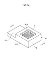
- the fourth exemplary embodiment differs from the third exemplary embodiment in the point that a empty case 8 is provided, the empty case 8 including a first empty case 81 in which the safety vent 1 is housed, and a second empty case 82 that is fixed to the gas spout out port 24 of the laminated exterior casing 21.
- the first empty case 81 has a flattened angular pipe shape and is bent into an L-shape as a whole.
- One end portion thereof is configured as a first joint portion that fits into the second empty case 82, while the other end portion thereof is configured as a housing case 812 in which the safety vent 1 is housed.
- the housing case 812 includes a gas spout out port 813 that is open at an upper face, and a bottom face 814.
- a gas passing hole 815 through which gas passes is formed at a central portion of the bottom face 814.
- the gas permeated membrane 4, the vent seat 32, the vent body 34, and the plane spring 31 are housed in that sequence from bottom to top inside the housing case 812.
- the gasket 35 is inserted between the vent seat 32 and the plane spring 31.
- the spring form fixing portion 36 is fitted in above the plane spring 31, thereby fixing the gas permeated membrane 4, the vent seat 32, the vent body 34, the gasket 35 and the plane spring 31 inside the housing case 812.
- the porous metallic foil body 37 is fixed to the gas spout out port 813.
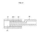
- the second empty case 82 is configured in a flattened pipe shape as a whole, with one end portion configuring a second joint portion 821 into which the first joint portion 811 of the first empty case 81 is inserted, and the other end portion configuring a third joint portion 822 that is fixed to the gas spout out port 24 of the laminated exterior casing 21.
- the third joint portion 822 is fixed to the gas spout out port 24 of the laminated exterior casing 21 using an adhesive 63.
- the first joint portion 811 of the first empty case 81 may be adhered and fixed, or may be detachably fitted, in a fitted together state with the second joint portion 821 of the second empty case 82.
- the safety vent 1 is fixed to the laminated exterior casing 21 with the empty case 8 interposed therebetween.
- the adhesion surface area between the empty case 8 (the second empty case 82) and the laminated exterior casing 21 can accordingly be made larger than the adhesion surface area between the housing case 5 and the laminated exterior casing 21 when the safety vent 1 is directly attached to the laminated exterior casing 21.
- the safety vent 1 can accordingly be more securely attached to the laminated exterior casing 21 than when the safety vent 1 is directly adhered and fixed to the laminated exterior casing 21.
- electrolyte can be introduced inside the laminate type battery 2 through the second empty case 82 after fixing the third joint portion 822 of the second empty case to the gas spout out port 24 provided to the exterior casing 21 of the laminate type battery 2 and prior to fitting the first joint portion 811 of the first empty case 81 into the second joint portion 821 of the second empty case 82 and joining together the first empty case 81 and the second empty case 82.
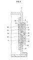
- a safety vent 1 of the fifth exemplary embodiment is configured such that the gas permeated membrane 4 and the vent 3 are housed inside a cylinder shaped housing case 10 that is fixed to the gas spout out port 24 of the laminated exterior casing 21.
- the housing case 10 is configured with a substantially circular cylinder shape provided so as to taper from the other end portion towards one end portion.
- a joint portion 13 that is a constriction side end portion is fixed to the gas spout out port 24 of the laminated exterior casing 21 using an adhesive 64. Note that face roughening treatment is performed on the surface of the joint portion 13 in order to secure adhesion force with the inside face of the laminated exterior casing 21.
- the gas permeated membrane 4, a ring shaped fixing member 91, the vent seat 32, the vent body 34 and the gasket 35, the plane spring 31, a ring shaped fixing member 92, the porous metallic foil body 37 and a ring shaped fixing member 93 are housed in that sequence inside the housing case 10 from the constriction end portion towards an enlarged end portion of the housing case 10.
- a circular ring shaped stopper 12 is provided to an inner wall face of the housing case 10 so as to project towards the radial direction inside.
- the gas permeated membrane 4 is fixed at a specific position by the stopper 12 and the ring shaped fixing member 91.
- the vent 3 that is configured by the vent seat 32, the vent body 34, the gasket 35, and the planar spring 31 is fixed by the ring shaped fixing member 91 and the ring shaped fixing member 92 such that a gap 11 is present between the vent 3 and the gas permeated membrane 4.
- the vent 3 and the gas permeated membrane 4 are integrated together by the housing case 10, and the housing case 10 is fixed to the laminated exterior casing 21 of the laminate type battery 2.
- the safety vent 1 can accordingly be easily and firmly attached to the laminated exterior casing 21 that is low in strength.
- the gap 11 is formed between the gas permeated membrane 4 and the vent 3. Pressure loss during gas release can accordingly be reduced further than in the safety vent 1 of the first exemplary embodiment to the fourth exemplary embodiment in which the gas permeated membrane 4 and the vent 3 are in close contact with each other.
- the housing case 10 of the safety vent 1 is configured with a tapered shape that gets smaller on progression towards the joint portion 13. Insertion of the joint portion 13 into the gas spout out port 24 of the laminated exterior casing 21 can accordingly be performed more easily than when an outer peripheral face of the housing case 10 is not configured with a tapered shape.
- Testing is also carried out for 10 standard laminate type lithium secondary batteries with LiCoOx anodes and artificial graphite cathodes.
- the lithium secondary batteries are employed in electric scooters and have a capacity of 20AH each. Testing is performed with the safety vent 1 of the fifth exemplary embodiment mounted to 5 out of the 10 lithium secondary batteries, and the safety vent 1 not mounted to the remaining 5 lithium secondary batteries.
- the external diameter of the joint portion 13 of the housing case 10 is 4mm.
- the internal diameter of the gas spout out port 24 into which the joint portion 13 of the housing case 10 is inserted is 4mm, and the external diameter of the gas spout out port 24 is 6mm.
- the porous metallic foil body 37 a spongiform nickel plate having a thickness of 1 mm and used for nickel-hydride secondary battery is employed.
- the planar spring 31 employed is configured as illustrated in Fig. 3 and is manufactured by Optnics Precision Co., Ltd., with a thickness of 50 ⁇ m and pressure regulated at 0.6kg/cm 2 .
- the gas permeated membrane 4 employed is manufactured by Optnics Precision Co., Ltd., and is configured with polyvinylidene fluoride coated on both faces of the base cloth 41 at a thickness of 2 ⁇ m.
- the base cloth 41 is a nonwoven fabric with a material thickness of 20 ⁇ m and with a fiber diameter or 3.0 ⁇ m obtained by electro-spinning a polyvinylidene fluoride resin and a polyacrylonitrile resin.
- test conditions are as set out below.
- the test conditions for the electric double layer capacitors are to perform charging 5 times a day for 25 days under conditions of 45°C and 40mA/F, monitoring the presence or absence of gas generation and of liquid leakage.
- the test conditions for the lithium secondary batteries are performing charging and discharging for 25 days under conditions of 5 cycles at a frequency of 2 times a day at 45°C, and at SOC, 80%, monitoring the presence or absence of gas generation and of liquid leakage. Results are illustrated in Table 1.
- an alkali activation carbon is employed in order to improve characteristics of an electric double layer capacitor.
- expensive, alkali activation carbons are effective in improving the capacity per unit.
- a tiny amount of remaining alkali acts as a catalyst, with the activated carbon oxidizing at usage of 2.5V to 2.9V and generating large amounts of gas, such that an electric double layer capacitor cannot be used without a self-retum type safety vent.
- the present invention provides a safety vent that can be securely and firmly attached to a laminated exterior casing that is low in strength in a laminate type electrochemical device such as an electric double layer capacitor or a lithium secondary battery.
- a laminate type electrochemical device such as an electric double layer capacitor or a lithium secondary battery.
- the safety vent is actuated when the internal pressure reaches a predetermined pressure, and electrolyte is separated from byproduct gas by a gas-liquid separating action, and the internally generated gas is allowed to release quickly to return the gas pressure to normal.
- the safety vent of the present invention accordingly includes the following features in comparison to conventional safety vents: (1) being driven by a lower pressure internal gas pressure; (2) separation of gas and liquid being performed quickly; (3) having a faster response speed; (4) being made thinner and more compact; (5) achieving higher reliability at a lower cost; and (6) having excellent mass production characteristics.
- the safety vent of the present invention is therefore preferably applied to electrochemical devices employed in large size equipment such as HEVs and PEVs, electrochemical devices used in equipment such as a construction machine or a bulldozer that can be used in a severe condition, and electrochemical devices employed in equipment such as large size smartphones.
Landscapes
- Chemical & Material Sciences (AREA)
- Chemical Kinetics & Catalysis (AREA)
- Electrochemistry (AREA)
- General Chemical & Material Sciences (AREA)
- Engineering & Computer Science (AREA)
- Power Engineering (AREA)
- Microelectronics & Electronic Packaging (AREA)
- Materials Engineering (AREA)
- Manufacturing & Machinery (AREA)
- Gas Exhaust Devices For Batteries (AREA)
- Electric Double-Layer Capacitors Or The Like (AREA)
- Sealing Battery Cases Or Jackets (AREA)
Applications Claiming Priority (2)
| Application Number | Priority Date | Filing Date | Title |
|---|---|---|---|
| JP2012075207 | 2012-03-28 | ||
| PCT/JP2013/058835 WO2013146803A1 (fr) | 2012-03-28 | 2013-03-26 | Soupape de sécurité et élément électrochimique |
Publications (2)
| Publication Number | Publication Date |
|---|---|
| EP2709191A1 true EP2709191A1 (fr) | 2014-03-19 |
| EP2709191A4 EP2709191A4 (fr) | 2015-08-19 |
Family
ID=49260054
Family Applications (1)
| Application Number | Title | Priority Date | Filing Date |
|---|---|---|---|
| EP13768899.0A Withdrawn EP2709191A4 (fr) | 2012-03-28 | 2013-03-26 | Soupape de sécurité et élément électrochimique |
Country Status (6)
| Country | Link |
|---|---|
| US (1) | US9397325B2 (fr) |
| EP (1) | EP2709191A4 (fr) |
| JP (1) | JP6085566B2 (fr) |
| KR (1) | KR101577883B1 (fr) |
| CN (1) | CN103597631B (fr) |
| WO (1) | WO2013146803A1 (fr) |
Cited By (12)
| Publication number | Priority date | Publication date | Assignee | Title |
|---|---|---|---|---|
| EP3046158A1 (fr) * | 2015-01-14 | 2016-07-20 | Samsung SDI Co., Ltd. | Batterie rechargeable et emballage associé |
| EP3336920A1 (fr) * | 2016-12-13 | 2018-06-20 | Lithium Energy and Power GmbH & Co. KG | Élément de batterie comprenant un limiteur de pression |
| WO2019226764A1 (fr) * | 2018-05-22 | 2019-11-28 | Johnson Controls Technology Company | Évent pour module de batterie |
| EP3567654A4 (fr) * | 2017-08-29 | 2020-04-22 | LG Chem, Ltd. | Batterie secondaire de type poche comprenant un dispositif d'induction de ventilation |
| EP3651235A4 (fr) * | 2018-05-10 | 2020-10-21 | Lg Chem, Ltd. | Dispositif de ventilation et son procédé de fabrication |
| EP3739664A1 (fr) * | 2019-05-14 | 2020-11-18 | Nitto Belgium NV | Valve de sécurité pour boîtiers de dispositif électrochimique |
| CN112639343A (zh) * | 2018-08-20 | 2021-04-09 | 大日本印刷株式会社 | 阀装置、收纳体、蓄电器件和阀装置的安装方法 |
| EP3754750A4 (fr) * | 2019-02-25 | 2021-07-14 | Lg Chem, Ltd. | Dispositif d'aération |
| EP4020675A1 (fr) * | 2020-12-22 | 2022-06-29 | Volkswagen AG | Cellule de sachet |
| DE102022205365A1 (de) | 2022-05-30 | 2023-11-30 | Volkswagen Aktiengesellschaft | Batteriezelle |
| EP4156397A4 (fr) * | 2020-07-10 | 2024-12-04 | LG Energy Solution, Ltd. | Batterie secondaire |
| EP4456313A3 (fr) * | 2021-08-06 | 2025-04-09 | Dai Nippon Printing Co., Ltd. | Dispositif de stockage d'énergie et procédé de production de dispositif de stockage d'énergie |
Families Citing this family (51)
| Publication number | Priority date | Publication date | Assignee | Title |
|---|---|---|---|---|
| KR102295629B1 (ko) | 2013-09-12 | 2021-08-27 | 가부시키가이샤 지에스 유아사 | 축전 장치 |
| DE102014202348A1 (de) * | 2014-02-10 | 2015-08-13 | Robert Bosch Gmbh | Vorrichtung und Verfahren zur Erhöhung der Sicherheit beim Gebrauch von Batteriesystemen |
| KR102275273B1 (ko) | 2014-07-29 | 2021-07-09 | 에스케이이노베이션 주식회사 | 파우치형 리튬 이차전지의 벤팅 시스템 |
| TWI517482B (zh) * | 2015-02-16 | 2016-01-11 | 有量科技股份有限公司 | 鋰電池的排氣結構 |
| KR102629819B1 (ko) * | 2016-02-19 | 2024-01-26 | 삼성에스디아이 주식회사 | 배터리 팩 |
| WO2018110067A1 (fr) * | 2016-12-16 | 2018-06-21 | 株式会社村田製作所 | Pile rechargeable, bloc-piles, véhicule électrique, système de stockage d'électricité, outil électrique et dispositif électronique |
| DE102017105286A1 (de) * | 2017-03-13 | 2018-09-13 | Dr. Ing. H.C. F. Porsche Aktiengesellschaft | Notentgasungsanordnung für ein Gehäuse im Kfz-Bereich |
| KR20250116186A (ko) | 2017-03-30 | 2025-07-31 | 도날드슨 컴파니, 인코포레이티드 | 릴리프 밸브를 갖는 통기구 |
| KR102173031B1 (ko) | 2017-07-04 | 2020-11-02 | 주식회사 엘지화학 | 이차전지 |
| KR102029163B1 (ko) * | 2018-03-22 | 2019-10-07 | 주식회사 엔투셀 | 가스 배출이 용이한 배터리 셀 및 벤트 수단의 제조 방법 |
| KR102386323B1 (ko) * | 2018-05-02 | 2022-04-14 | 주식회사 엘지에너지솔루션 | 벤팅 장치 및 그의 제조 방법 |
| JP2019200888A (ja) * | 2018-05-15 | 2019-11-21 | Smk株式会社 | 防爆弁、防爆弁ユニット、防爆弁の製造方法及び防爆弁ユニットの製造方法 |
| JP7040293B2 (ja) * | 2018-05-28 | 2022-03-23 | 大日本印刷株式会社 | 電池 |
| JP6996422B2 (ja) * | 2018-05-28 | 2022-02-21 | 大日本印刷株式会社 | 電池 |
| JP6996421B2 (ja) * | 2018-05-28 | 2022-02-21 | 大日本印刷株式会社 | 電池、ヒートシール装置、及び電池の製造方法 |
| JP7040294B2 (ja) * | 2018-05-28 | 2022-03-23 | 大日本印刷株式会社 | 電池 |
| KR102323809B1 (ko) | 2018-06-18 | 2021-11-09 | 주식회사 엘지에너지솔루션 | 벤팅 장치 및 그의 제조 방법 |
| JP6989706B2 (ja) * | 2018-07-31 | 2022-01-05 | 株式会社東芝 | 二次電池及び電池パック |
| JP7205136B2 (ja) | 2018-09-25 | 2023-01-17 | 大日本印刷株式会社 | 蓄電デバイス用弁装置及び蓄電デバイス |
| JP7187927B2 (ja) * | 2018-09-25 | 2022-12-13 | 大日本印刷株式会社 | 蓄電デバイス |
| JP2020063059A (ja) * | 2018-10-15 | 2020-04-23 | 大日本印刷株式会社 | 弁構造体及びこれを備える包装体 |
| JP6540871B1 (ja) * | 2018-10-18 | 2019-07-10 | 大日本印刷株式会社 | 蓄電デバイス用弁装置及び蓄電デバイス |
| JP6821635B2 (ja) * | 2018-10-22 | 2021-01-27 | 大日本印刷株式会社 | 弁装置、収容体及び弁装置の取付方法 |
| JP6530849B1 (ja) * | 2018-10-22 | 2019-06-12 | 大日本印刷株式会社 | 電池 |
| JP6530848B1 (ja) * | 2018-10-22 | 2019-06-12 | 大日本印刷株式会社 | 電池、ヒートシール装置、及び電池の製造方法 |
| JP6530850B1 (ja) * | 2018-10-22 | 2019-06-12 | 大日本印刷株式会社 | 電池 |
| JP6530847B1 (ja) * | 2018-10-22 | 2019-06-12 | 大日本印刷株式会社 | 電池 |
| CN113228395B (zh) * | 2018-12-26 | 2023-07-25 | 大日本印刷株式会社 | 阀装置和电池组 |
| KR102892123B1 (ko) * | 2019-04-26 | 2025-11-26 | 다이니폰 인사츠 가부시키가이샤 | 축전 디바이스용 밸브 구조체 |
| JP6653038B1 (ja) * | 2019-04-26 | 2020-02-26 | 大日本印刷株式会社 | 蓄電デバイス用弁構造体 |
| JP2024045178A (ja) * | 2019-06-12 | 2024-04-02 | 大日本印刷株式会社 | 蓄電デバイス用弁装置及び蓄電デバイス |
| KR102937899B1 (ko) * | 2019-08-27 | 2026-03-11 | 주식회사 엘지에너지솔루션 | 이차 전지용 전지 케이스 및 파우치 형 이차 전지 제조 방법 |
| KR102804032B1 (ko) | 2019-08-27 | 2025-05-09 | 주식회사 엘지에너지솔루션 | 이차 전지용 전지 케이스 및 파우치 형 이차 전지 제조 방법 |
| KR102742762B1 (ko) * | 2019-09-23 | 2024-12-16 | 주식회사 엘지에너지솔루션 | 이차전지 제조방법 및 이차전지 |
| KR102818309B1 (ko) * | 2019-10-10 | 2025-06-10 | 주식회사 엘지에너지솔루션 | 이차전지용 가스 배출 장치 및 이차전지 |
| KR102332931B1 (ko) * | 2019-11-29 | 2021-11-30 | 한국제이씨씨(주) | 고전압용 캔형 전기 이중층 커패시터 |
| WO2021117408A1 (fr) * | 2019-12-09 | 2021-06-17 | パナソニック株式会社 | Batterie secondaire à électrolyte non aqueux et procédé de fabrication de batterie secondaire à électrolyte non aqueux |
| JP7563885B2 (ja) * | 2020-03-04 | 2024-10-08 | 本田技研工業株式会社 | 車両 |
| KR102397819B1 (ko) * | 2020-03-27 | 2022-05-13 | 한국제이씨씨(주) | 에너지 저장장치용 안전밸브 |
| KR102756131B1 (ko) * | 2020-06-15 | 2025-01-17 | 주식회사 엘지에너지솔루션 | 이차전지 |
| CN114198543B (zh) * | 2020-08-31 | 2023-08-08 | 宁德时代新能源科技股份有限公司 | 双向泄压阀、电池以及用电装置 |
| US11824220B2 (en) * | 2020-09-03 | 2023-11-21 | Apple Inc. | Electronic device having a vented battery barrier |
| JP7787822B2 (ja) * | 2020-11-06 | 2025-12-17 | エルジー エナジー ソリューション リミテッド | 電池セル及びそれを含む電池モジュール |
| US20220190434A1 (en) * | 2020-12-11 | 2022-06-16 | GM Global Technology Operations LLC | Composite battery cover |
| CN115136396B (zh) | 2021-01-11 | 2024-06-18 | 株式会社Lg新能源 | 电池单元和包括该电池单元的电池模块 |
| KR20220142964A (ko) * | 2021-04-15 | 2022-10-24 | 주식회사 엘지에너지솔루션 | 이차전지 |
| WO2022252108A1 (fr) | 2021-06-01 | 2022-12-08 | 宁德时代新能源科技股份有限公司 | Ensemble couvercle d'extrémité, élément de batterie, batterie et appareil à consommation d'énergie |
| KR102710217B1 (ko) * | 2021-12-15 | 2024-09-26 | 주식회사 에스에프에이 | 이차전지용 프리차저 |
| CN119790534A (zh) | 2022-09-07 | 2025-04-08 | 唐纳森公司 | 破裂式阀 |
| JP7639998B2 (ja) * | 2023-03-06 | 2025-03-05 | 大日本印刷株式会社 | 蓄電デバイス、蓋ユニット |
| KR102798645B1 (ko) * | 2023-08-10 | 2025-04-23 | 주식회사 엘지에너지솔루션 | 파우치 셀 |
Family Cites Families (17)
| Publication number | Priority date | Publication date | Assignee | Title |
|---|---|---|---|---|
| JPH05159765A (ja) | 1991-12-04 | 1993-06-25 | Japan Gore Tex Inc | 電池用電解液漏れ防止膜 |
| DE4203332A1 (de) | 1992-02-06 | 1993-08-12 | Varta Batterie | Verschlussstopfen fuer elektrische akkumulatoren |
| US6521024B1 (en) * | 1999-03-18 | 2003-02-18 | Nok Corporation | Seal plate and pressure adjusting mechanism for the seal plate |
| JP2003037028A (ja) * | 2001-07-26 | 2003-02-07 | Shizuki Electric Co Inc | コンデンサ |
| US20030049521A1 (en) | 2001-09-11 | 2003-03-13 | Japan Storage Battery Co., Ltd. | Lead acid battery |
| TWI300637B (en) * | 2002-09-27 | 2008-09-01 | Sony Corp | Battery pack and method for producing same |
| JP5031559B2 (ja) * | 2004-06-17 | 2012-09-19 | コリア リサーチ インスティチュート オブ ケミカル テクノロジー | フィラメント束状の長繊維及びその製造方法 |
| JP2006156868A (ja) * | 2004-12-01 | 2006-06-15 | Nok Corp | 圧力開放弁 |
| JP2007157678A (ja) | 2005-05-23 | 2007-06-21 | Matsushita Electric Ind Co Ltd | ラミネート電池の安全機構 |
| CN200990403Y (zh) * | 2005-06-28 | 2007-12-12 | 董家琼 | 一种二次锂离子电池及二次锂离子电池组 |
| US20100227544A1 (en) * | 2005-12-14 | 2010-09-09 | Nitto Denko Corporation | Vent Member and Vent Structure |
| JP5127258B2 (ja) * | 2007-02-08 | 2013-01-23 | 株式会社オプトニクス精密 | ガス透過性安全弁および電気化学素子 |
| JP2008166833A (ja) * | 2008-01-28 | 2008-07-17 | Power System:Kk | 電子部品のガス抜き部の構造 |
| WO2009104701A1 (fr) | 2008-02-22 | 2009-08-27 | 旭硝子株式会社 | Procédé de fabrication d'un ensemble d'électrode de membrane pour pile à combustible solide |
| JP2009224228A (ja) * | 2008-03-17 | 2009-10-01 | Toshiba Corp | 電池モジュール及び電池パック |
| JP5289164B2 (ja) * | 2009-04-24 | 2013-09-11 | 株式会社オプトニクス精密 | 面状ばね及びこれを用いた安全弁 |
| CN201796965U (zh) * | 2010-06-10 | 2011-04-13 | 天津佰特瑞电子有限公司 | 一种锂离子动力电池防爆盖帽 |
-
2013
- 2013-03-26 EP EP13768899.0A patent/EP2709191A4/fr not_active Withdrawn
- 2013-03-26 JP JP2013543435A patent/JP6085566B2/ja not_active Expired - Fee Related
- 2013-03-26 WO PCT/JP2013/058835 patent/WO2013146803A1/fr not_active Ceased
- 2013-03-26 KR KR1020137032061A patent/KR101577883B1/ko not_active Expired - Fee Related
- 2013-03-26 US US14/123,228 patent/US9397325B2/en not_active Expired - Fee Related
- 2013-03-26 CN CN201380001566.XA patent/CN103597631B/zh not_active Expired - Fee Related
Cited By (20)
| Publication number | Priority date | Publication date | Assignee | Title |
|---|---|---|---|---|
| US9705153B2 (en) | 2015-01-14 | 2017-07-11 | Samsung Sdi Co., Ltd. | Rechargeable battery and pack of the same |
| EP3046158A1 (fr) * | 2015-01-14 | 2016-07-20 | Samsung SDI Co., Ltd. | Batterie rechargeable et emballage associé |
| EP3336920A1 (fr) * | 2016-12-13 | 2018-06-20 | Lithium Energy and Power GmbH & Co. KG | Élément de batterie comprenant un limiteur de pression |
| WO2018108713A1 (fr) * | 2016-12-13 | 2018-06-21 | Lithium Energy and Power GmbH & Co. KG | Élément de batterie pourvu d'une soupape de sûreté |
| US11189881B2 (en) | 2017-08-29 | 2021-11-30 | Lg Chem, Ltd. | Pouch-shaped secondary battery comprising venting guidance device |
| EP3567654A4 (fr) * | 2017-08-29 | 2020-04-22 | LG Chem, Ltd. | Batterie secondaire de type poche comprenant un dispositif d'induction de ventilation |
| EP3651235A4 (fr) * | 2018-05-10 | 2020-10-21 | Lg Chem, Ltd. | Dispositif de ventilation et son procédé de fabrication |
| US11539098B2 (en) | 2018-05-10 | 2022-12-27 | Lg Energy Solution, Ltd. | Venting device and method for manufacturing the same |
| WO2019226764A1 (fr) * | 2018-05-22 | 2019-11-28 | Johnson Controls Technology Company | Évent pour module de batterie |
| EP3842677A4 (fr) * | 2018-08-20 | 2022-05-18 | Dai Nippon Printing Co., Ltd. | Dispositif de soupape, corps de stockage, dispositif de stockage d'énergie, et procédé de fixation du dispositif de soupape |
| CN112639343A (zh) * | 2018-08-20 | 2021-04-09 | 大日本印刷株式会社 | 阀装置、收纳体、蓄电器件和阀装置的安装方法 |
| EP3754750A4 (fr) * | 2019-02-25 | 2021-07-14 | Lg Chem, Ltd. | Dispositif d'aération |
| US11581600B2 (en) | 2019-02-25 | 2023-02-14 | Lg Energy Solution, Ltd. | Venting device |
| EP4350848A3 (fr) * | 2019-02-25 | 2024-06-05 | Lg Energy Solution, Ltd. | Dispositif de ventilation |
| EP3739667A1 (fr) | 2019-05-14 | 2020-11-18 | Nitto Belgium NV | Valve de sécurité pour boîtiers de dispositif électrochimique |
| EP3739664A1 (fr) * | 2019-05-14 | 2020-11-18 | Nitto Belgium NV | Valve de sécurité pour boîtiers de dispositif électrochimique |
| EP4156397A4 (fr) * | 2020-07-10 | 2024-12-04 | LG Energy Solution, Ltd. | Batterie secondaire |
| EP4020675A1 (fr) * | 2020-12-22 | 2022-06-29 | Volkswagen AG | Cellule de sachet |
| EP4456313A3 (fr) * | 2021-08-06 | 2025-04-09 | Dai Nippon Printing Co., Ltd. | Dispositif de stockage d'énergie et procédé de production de dispositif de stockage d'énergie |
| DE102022205365A1 (de) | 2022-05-30 | 2023-11-30 | Volkswagen Aktiengesellschaft | Batteriezelle |
Also Published As
| Publication number | Publication date |
|---|---|
| WO2013146803A1 (fr) | 2013-10-03 |
| JP6085566B2 (ja) | 2017-02-22 |
| EP2709191A4 (fr) | 2015-08-19 |
| KR20140053010A (ko) | 2014-05-07 |
| US20140120387A1 (en) | 2014-05-01 |
| CN103597631B (zh) | 2016-02-03 |
| CN103597631A (zh) | 2014-02-19 |
| US9397325B2 (en) | 2016-07-19 |
| JPWO2013146803A1 (ja) | 2015-12-14 |
| KR101577883B1 (ko) | 2015-12-15 |
Similar Documents
| Publication | Publication Date | Title |
|---|---|---|
| EP2709191A1 (fr) | Soupape de sécurité et élément électrochimique | |
| US8734984B2 (en) | Bipolar battery manufacturing method, and bipolar battery | |
| US20190097228A1 (en) | Nonaqueous electrolyte secondary battery | |
| US10651448B2 (en) | Secondary cell | |
| JP5127258B2 (ja) | ガス透過性安全弁および電気化学素子 | |
| US11502382B2 (en) | Nonaqueous electrolyte secondary battery | |
| US20200303782A1 (en) | Nonaqueous electrolyte secondary battery | |
| JP6264891B2 (ja) | 電極、および電極を有する電池 | |
| EP3813178B1 (fr) | Batterie secondaire à électrolyte non aqueux | |
| JP7317823B2 (ja) | 非水電解質二次電池 | |
| US20170317326A1 (en) | Battery | |
| JP6951002B2 (ja) | 二次電池用電解液、これを含むバッテリーおよびフレキシブルバッテリー | |
| JP2022152423A (ja) | 円筒形電池 | |
| US20220344670A1 (en) | Electrode current collector and secondary battery | |
| JP2018060670A (ja) | 蓄電装置 | |
| CN114556678A (zh) | 具有改进的气体与湿气渗透率比的电池 | |
| KR20170095729A (ko) | 전기 화학 디바이스 및 전기 화학 디바이스의 제조 방법 | |
| JP6606341B2 (ja) | 電極および電池 | |
| US20210376390A1 (en) | Nonaqueous electrolyte secondary battery and method for manufacturing nonaqueous electrolyte secondary batteries | |
| JP2003217671A (ja) | 密閉型電池の製造方法と密閉型電池のシール性評価方法 | |
| KR20030096025A (ko) | 축전 소자 및 그 제조 방법 | |
| KR20160009414A (ko) | 플렉서블 배터리용 파우치 및 이를 이용한 플렉서블 배터리 | |
| JP7664533B2 (ja) | 電気化学デバイスおよびその製造方法 | |
| KR20160002094A (ko) | 플렉서블 배터리용 파우치, 이를 이용한 플렉서블 배터리 및 그의 제조 방법 | |
| KR102386690B1 (ko) | 전해액 토출이 제어되는 파우치형 이차전지의 제조방법 및 이에 사용되는 장치 |
Legal Events
| Date | Code | Title | Description |
|---|---|---|---|
| PUAI | Public reference made under article 153(3) epc to a published international application that has entered the european phase |
Free format text: ORIGINAL CODE: 0009012 |
|
| 17P | Request for examination filed |
Effective date: 20131202 |
|
| AK | Designated contracting states |
Kind code of ref document: A1 Designated state(s): AL AT BE BG CH CY CZ DE DK EE ES FI FR GB GR HR HU IE IS IT LI LT LU LV MC MK MT NL NO PL PT RO RS SE SI SK SM TR |
|
| DAX | Request for extension of the european patent (deleted) | ||
| RA4 | Supplementary search report drawn up and despatched (corrected) |
Effective date: 20150717 |
|
| RIC1 | Information provided on ipc code assigned before grant |
Ipc: H01M 2/02 20060101ALI20150713BHEP Ipc: H01M 2/12 20060101AFI20150713BHEP Ipc: H01G 11/78 20130101ALI20150713BHEP Ipc: H01M 10/0525 20100101ALI20150713BHEP Ipc: H01G 11/18 20130101ALI20150713BHEP Ipc: H01G 11/00 20130101ALI20150713BHEP |
|
| 17Q | First examination report despatched |
Effective date: 20170209 |
|
| STAA | Information on the status of an ep patent application or granted ep patent |
Free format text: STATUS: THE APPLICATION IS DEEMED TO BE WITHDRAWN |
|
| 18D | Application deemed to be withdrawn |
Effective date: 20170620 |