EP4020675A1 - Cellule de sachet - Google Patents
Cellule de sachet Download PDFInfo
- Publication number
- EP4020675A1 EP4020675A1 EP21208556.7A EP21208556A EP4020675A1 EP 4020675 A1 EP4020675 A1 EP 4020675A1 EP 21208556 A EP21208556 A EP 21208556A EP 4020675 A1 EP4020675 A1 EP 4020675A1
- Authority
- EP
- European Patent Office
- Prior art keywords
- pouch
- degassing channel
- bag
- cell
- degassing
- Prior art date
- Legal status (The legal status is an assumption and is not a legal conclusion. Google has not performed a legal analysis and makes no representation as to the accuracy of the status listed.)
- Pending
Links
Images

Classifications
-
- H—ELECTRICITY
- H01—ELECTRIC ELEMENTS
- H01M—PROCESSES OR MEANS, e.g. BATTERIES, FOR THE DIRECT CONVERSION OF CHEMICAL ENERGY INTO ELECTRICAL ENERGY
- H01M50/00—Constructional details or processes of manufacture of the non-active parts of electrochemical cells other than fuel cells, e.g. hybrid cells
- H01M50/30—Arrangements for facilitating escape of gases
- H01M50/342—Non-re-sealable arrangements
-
- H—ELECTRICITY
- H01—ELECTRIC ELEMENTS
- H01M—PROCESSES OR MEANS, e.g. BATTERIES, FOR THE DIRECT CONVERSION OF CHEMICAL ENERGY INTO ELECTRICAL ENERGY
- H01M10/00—Secondary cells; Manufacture thereof
- H01M10/05—Accumulators with non-aqueous electrolyte
- H01M10/052—Li-accumulators
-
- H—ELECTRICITY
- H01—ELECTRIC ELEMENTS
- H01M—PROCESSES OR MEANS, e.g. BATTERIES, FOR THE DIRECT CONVERSION OF CHEMICAL ENERGY INTO ELECTRICAL ENERGY
- H01M50/00—Constructional details or processes of manufacture of the non-active parts of electrochemical cells other than fuel cells, e.g. hybrid cells
- H01M50/10—Primary casings; Jackets or wrappings
- H01M50/102—Primary casings; Jackets or wrappings characterised by their shape or physical structure
- H01M50/105—Pouches or flexible bags
-
- H—ELECTRICITY
- H01—ELECTRIC ELEMENTS
- H01M—PROCESSES OR MEANS, e.g. BATTERIES, FOR THE DIRECT CONVERSION OF CHEMICAL ENERGY INTO ELECTRICAL ENERGY
- H01M50/00—Constructional details or processes of manufacture of the non-active parts of electrochemical cells other than fuel cells, e.g. hybrid cells
- H01M50/20—Mountings; Secondary casings or frames; Racks, modules or packs; Suspension devices; Shock absorbers; Transport or carrying devices; Holders
- H01M50/249—Mountings; Secondary casings or frames; Racks, modules or packs; Suspension devices; Shock absorbers; Transport or carrying devices; Holders specially adapted for aircraft or vehicles, e.g. cars or trains
-
- H—ELECTRICITY
- H01—ELECTRIC ELEMENTS
- H01M—PROCESSES OR MEANS, e.g. BATTERIES, FOR THE DIRECT CONVERSION OF CHEMICAL ENERGY INTO ELECTRICAL ENERGY
- H01M50/00—Constructional details or processes of manufacture of the non-active parts of electrochemical cells other than fuel cells, e.g. hybrid cells
- H01M50/30—Arrangements for facilitating escape of gases
-
- H—ELECTRICITY
- H01—ELECTRIC ELEMENTS
- H01M—PROCESSES OR MEANS, e.g. BATTERIES, FOR THE DIRECT CONVERSION OF CHEMICAL ENERGY INTO ELECTRICAL ENERGY
- H01M50/00—Constructional details or processes of manufacture of the non-active parts of electrochemical cells other than fuel cells, e.g. hybrid cells
- H01M50/30—Arrangements for facilitating escape of gases
- H01M50/317—Re-sealable arrangements
-
- H—ELECTRICITY
- H01—ELECTRIC ELEMENTS
- H01M—PROCESSES OR MEANS, e.g. BATTERIES, FOR THE DIRECT CONVERSION OF CHEMICAL ENERGY INTO ELECTRICAL ENERGY
- H01M2220/00—Batteries for particular applications
- H01M2220/20—Batteries in motive systems, e.g. vehicle, ship, plane
-
- H—ELECTRICITY
- H01—ELECTRIC ELEMENTS
- H01M—PROCESSES OR MEANS, e.g. BATTERIES, FOR THE DIRECT CONVERSION OF CHEMICAL ENERGY INTO ELECTRICAL ENERGY
- H01M50/00—Constructional details or processes of manufacture of the non-active parts of electrochemical cells other than fuel cells, e.g. hybrid cells
- H01M50/30—Arrangements for facilitating escape of gases
- H01M50/308—Detachable arrangements, e.g. detachable vent plugs or plug systems
-
- Y—GENERAL TAGGING OF NEW TECHNOLOGICAL DEVELOPMENTS; GENERAL TAGGING OF CROSS-SECTIONAL TECHNOLOGIES SPANNING OVER SEVERAL SECTIONS OF THE IPC; TECHNICAL SUBJECTS COVERED BY FORMER USPC CROSS-REFERENCE ART COLLECTIONS [XRACs] AND DIGESTS
- Y02—TECHNOLOGIES OR APPLICATIONS FOR MITIGATION OR ADAPTATION AGAINST CLIMATE CHANGE
- Y02E—REDUCTION OF GREENHOUSE GAS [GHG] EMISSIONS, RELATED TO ENERGY GENERATION, TRANSMISSION OR DISTRIBUTION
- Y02E60/00—Enabling technologies; Technologies with a potential or indirect contribution to GHG emissions mitigation
- Y02E60/10—Energy storage using batteries
Definitions
- the invention relates to a pouch cell and a vehicle battery with such a pouch cell.
- Motor vehicles that are driven or can be driven electrically or by an electric motor such as electric or hybrid vehicles, generally include an electric motor with which one or both vehicle axles can be driven.
- the electric motor is usually connected to a vehicle-internal (high-voltage) battery as an electrical energy store.
- a battery in particular an electrochemical battery, is to be understood here and in the following in particular as a so-called secondary battery (secondary battery) of the motor vehicle.
- secondary battery secondary battery
- Such vehicle batteries are designed, for example, as electrochemical accumulators, in particular as lithium-ion accumulators.
- electrochemical accumulators in particular as lithium-ion accumulators.
- vehicle batteries typically have at least one battery cell module in which several individual battery cells are connected in a modular manner.
- the battery cells are designed, for example, as electrochemical (thin) layer cells.
- the thin-film cells have a layered structure with a cathode layer (cathode) and with an anode layer (anode) and with a separator layer (separator) introduced in between.
- These components are permeated, for example, by a liquid electrolyte (liquid electrolyte), which creates an ionically conductive connection between the components or charge equalization.
- liquid electrolyte liquid electrolyte
- several layered cells are arranged stacked on top of one another as a cell stack.
- an active material or electrode material layer is applied to a current conductor (conductor tab).
- the conductor lugs are often designed as metal foils, with copper foils typically being used for the anode layers and aluminum foils for the cathode layers.
- Coated like that Current collectors or collector tabs are used as stacked electrodes (electrode stack).
- the conductor lugs of the electrode or cell stack are electrically contacted with one another to form a common anode and a common cathode, which are also referred to below as current collectors.
- a cell housing In order to protect the cell stack (electrode stack) against the ingress of moisture and/or dirt and, on the other hand, to prevent chemicals or the liquid electrolyte from escaping in the event of damage to the battery cell, a cell housing is usually provided as an enclosure or casing.
- the cell housing is designed, for example, as an aluminum composite film or as an aluminum laminate film, such flexible or film-like cell housings also being referred to as pouch bags or pouch film jackets and battery cells with such a cell housing also being referred to as pouch cells or soft pack cells.
- Such pouches are made, for example, from a single folded pouch sheet or from two joined pouch halves.
- the bag sheet or the bag halves are generally designed as deep-drawn pouch films, which are joined to form a tight pouch bag all the way around, for example by means of a heat-sealing process.
- decomposition reactions occur within the battery or pouch cell, which outgas, i.e. produce a gaseous reaction or formation product. This gas formation or gas development occurs increasingly during a charging process.
- the gases that form accumulate inside the pouch cell and cause an increase in volume or volume expansion of the pouch cell or the pouch bag and/or other undesired side reactions.
- the gas-related increase in volume of the pouch cell can lead to damage (cracks) or complete destruction of the battery or the pouch bag, in particular due to aging gases or thermal runaway.
- the pouch cell can open in an uncontrolled manner along the circumferential sealing seams, i.e. at an unforeseeable position, and outgas in an undirected or uncontrolled manner into the installation space of the battery module or battery system.
- Such uncontrolled degassing of the pouch cell in all spatial directions can lead to damage or complete destruction of components in the installation space environment. This is particularly critical with regard to components that perform important or safety-related functions. These components must therefore be protected from damage by additional package measures will. These measures cause additional costs and require space, which consequently reduces the energy density of the battery system.
- the degassing valve has a gas-permeable membrane, which is designed as a porous solid membrane.
- the membrane is covered, for example, with a material or a film that melts at a critical temperature of the battery cell and/or detaches from the pores at a critical pressure.
- the invention is based on the object of specifying a particularly suitable pouch cell.
- a controlled opening of the pouch should be made possible in the event of an impermissible internal pressure.
- the invention also relates to a vehicle battery with such a pouch cell.
- the object is achieved with the features of claim 1 and with regard to the vehicle battery with the features of claim 10.
- Advantageous refinements and developments are the subject of the dependent claims.
- the advantages and configurations listed with regard to the pouch cell can also be transferred to the vehicle battery and vice versa.
- the pouch cell according to the invention is designed as a battery cell in pouch or soft bag format and has a particularly fluid-tight pouch bag as the cell housing, through which a degassing channel passes, for example vertically.
- a degassing channel is integrated into the pouch bag.
- the degassing channel here connects a bag interior with an environment.
- the interior of the pouch is the volume or installation space enclosed by the pouch, the environment being the space surrounding the pouch cell.
- The, for example, tubular or hollow-cylindrical degassing channel is therefore designed as a through-opening of the pouch bag.
- the degassing channel is a closing one locking element used.
- the closure element is designed in such a way that when excess pressure occurs in the interior of the bag, the closure element is pressed out of the degassing channel by the excess pressure, thereby releasing or opening the degassing channel. In the released or open state, a flow and pressure connection is established between the interior of the bag and the environment.
- the degassing channel can be arranged individually on each side of the pouch.
- the degassing channel and the closing element thus act in the manner of an overpressure valve (safety valve) or a bursting disc in order to reduce a critical overpressure from the inside of the bag and thus to avoid damage or destruction of the pouch bag.
- a particularly suitable pouch cell is thereby realized.
- the pouch cell in the event of an error (overpressure), the pouch cell is automatically or automatically opened locally at a defined point or position. This enables local, controlled and directed degassing, which improves the security of the pouch cell.
- safety is improved.
- the pouch is sealed in a fluid-tight manner by means of a joint, with the degassing channel penetrating the pouch in the area of the joint.
- the degassing channel can preferably be arranged individually on each side of the pouch with a joint.
- the pouch bag is formed, for example, from two bag halves joined circumferentially.
- the halves of the bag are designed as deep-drawn pouch films.
- the pouch film is designed, for example, as an aluminum composite film or as an aluminum laminate film and has a polypropylene (PP) and/or polyester (PET) component, for example.
- PP polypropylene
- PET polyester
- the bag halves, which are in particular deep-drawn, are joined to form the pouch bag in a materially bonded manner.
- the halves of the bag are joined, for example, with a defined pressure and with a defined (sealing) time and a defined (sealing) temperature in a heat-sealing process, so that a peripheral, edge, welded or sealed seam is produced as a joint.
- the pouch bag can also be designed as a single bag sheet or (pouch) film sheet, which is folded into a bag shape by means of bends.
- the sheet of the bag is folded in the middle (horizontally), with a circumferential three-sided seal or joint connection taking place on the opened bag sides.
- An electrode stack (cell stack) is preferably accommodated in the pouch of the pouch cell.
- the electrode stack has, for example, a number of thin-film cells arranged stacked one on top of the other, with a cathode layer and with an anode layer and with a separator layer (separator) introduced in between.
- a liquid electrolyte for example, which penetrates the electrode stack, is accommodated in the pouch.
- the degassing channel is preferably arranged on a side of the pouch which does not face a subsurface or a bottom of the vehicle battery. This means that the degassing channel is arranged upwards or horizontally in the installation situation, so that the liquid electrolyte does not run out when the degassing channel is opened.
- the degassing channel is closed in a fluid-tight and pressure-tight manner by the closing element.
- the closing element is preferably chemically inert with respect to the liquid electrolyte.
- the closing element is introduced into the degassing channel as a plastic mass.
- the plastic mass is in particular an elastic sealing or adhesive mass.
- the plasticity or (deformable) formability of the closing element ensures that the volume of the degassing channel is filled as completely as possible, so that the pouch bag is reliably closed in a fluid-tight and pressure-tight manner by means of the closing element.
- the plastic mass can, for example, be hardened or solidified after it has been introduced into the degassing channel, so that the closing element is essentially designed as a plug.
- the mass is designed as a two-component epoxy, which hardens after it has been introduced into the degassing channel.
- the closing element that is to say the plastic mass, is not hardened after it has been introduced.
- the plastic mass can be designed as a permanently plastic mass.
- the closing element is made from a butyl rubber or an adhesive putty.
- degassing channel is open in the course of an evacuation process of the interior of the bag, and after the evacuation process is sealed with the closing element in a fluid-tight and pressure-tight manner.
- the degassing channel is thus introduced into the pouch bag or into the joint in such a way that the pouch cell can be evacuated after formation.
- the degassing channel is then closed with the closing element.
- the degassing channel is designed as a cannula.
- a cannula is to be understood in particular as a small tube which is inserted into the pouch bag and transports air or liquid into it or drains it out of it.
- a particularly suitable design of the degassing channel is realized.
- the cannula has, for example, a round, in particular circular, cross-sectional shape with a diameter of between 1 mm (millimeter) and 1 cm (centimeter), in particular between 1 mm and 5 mm, preferably between 2 mm and 3 mm.
- a round, in particular circular, cross-sectional shape with a diameter of between 1 mm (millimeter) and 1 cm (centimeter), in particular between 1 mm and 5 mm, preferably between 2 mm and 3 mm.
- Equally conceivable are, for example, oval or polygonal cross-sectional shapes, such as triangular or rectangular.
- the cannula is preferably arranged between the halves of the bag and then joined to them in a materially bonded manner and sealed on the peripheral side.
- the geometry or cross-sectional shape of the cannula is preferably designed in such a way that the cannula can be easily heat-sealed.
- the cannula is sealed off from the pouch by means of a sealant or adhesive, in particular a hot-melt adhesive. It is also conceivable for the cannula to be sheathed or coated with a plastic material, which is joined to the plastic material of the pouch films.
- the degassing channel or the cannula is made from a corresponding plastic material.
- the degassing channel is preferably bonded to the material of the pouch.
- the degassing channel is made from the plastic of the pouch film, such as polypropylene (PP), so that in the course of a heat-sealing process for producing the peripheral joint connection, a direct or immediate material joint connection between the degassing channel and the pouch films is also effected.
- a (dimensionally) stable core is suitably introduced into the degassing channel during the heat-sealing process, so that it is not deformed or closed during the heat-sealing. The core is removed after the joining process.
- the closure element is pushed or pressed out of the degassing channel automatically or automatically when the overpressure or internal pressure of the bag interior is sufficiently high.
- An integral connection is preferably realized between the closing element and the degassing channel. Additionally or alternatively, a non-positive and/or positive connection can also be provided between the closing element and the degassing channel.
- a “material connection” or a “material connection” between at least two parts connected to one another is understood here and in the following in particular to mean that the parts connected to one another at their contact surfaces through material union or crosslinking (e.g. due to atomic or molecular bonding forces) may be under the effect an additive are held together.
- a "positive fit” or a "positive connection” between at least two parts connected to one another is understood here and in the following in particular to mean that the parts connected to one another are held together at least in one direction by direct interlocking of the contours of the parts themselves or by indirect interlocking via an additional connection part.
- the "blocking" of a mutual movement in this direction is therefore due to the shape.
- a “positive connection” or a “positive connection” between at least two parts connected to one another is understood here and in the following in particular to mean that the parts connected to one another are prevented from sliding off one another due to a frictional force acting between them. If there is no "connection force” that causes this frictional force (this means the force that presses the parts against one another, for example a screw force or the force of weight itself), the non-positive connection cannot be maintained and can therefore be released.
- the setting at which excess pressure the degassing channel is opened can thus be made by a suitable choice of the geometry and dimensioning and material of the degassing channel and by selecting the material and the dimensioning of the closing element.
- the overpressure for an uncontrolled bursting open of the sealing seams of the pouch is around 3 bar, for example.
- the closing element is designed in such a way that it is pressed out of the degassing channel at an overpressure of between 2 bar and 3 bar, in particular between 2 bar and 2.5 bar.
- opening pressure At least a certain safety distance or safety offset to the critical (fault) pressure is preferably always provided. This ensures that the pouch is opened locally before it degasses in an uncontrolled and undirected manner.
- the vehicle battery according to the invention is designed in particular as a traction battery of an electrically driven or drivable motor vehicle, for example an electric or hybrid vehicle.
- the vehicle battery has, for example, a battery module with at least one pouch cell described above.
- the battery module suitably has a number of pouch cells according to the invention, which are electrically interconnected.
- the pouch cells according to the invention advantageously and easily avoid uncontrolled degassing in all spatial directions. As a result, damage to or destruction of components in the installation space surrounding the pouch cells is essentially ruled out. This means that additional package measures for safety-relevant battery components can be dispensed with.
- the vehicle battery according to the invention is therefore particularly inexpensive and has a particularly high energy density.
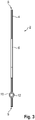
- the 1 shows a pouch cell 2 with an approximately rectangular pouch bag 4, in which an electrode stack, not shown, is arranged.
- the pouch cell 2 is, for example, part of a vehicle battery that is not shown in detail.
- Two connection tabs 6 protrude from the pouch bag 4 on the opposite short or end sides as electrical connection contacts for contacting and interconnecting the pouch cell 2 or the electrode stack.
- the connection tabs 6 form the cathode and anode of the pouch cell 2.
- the pouch bag 4 is formed by two peripherally joined bag halves.
- the bag halves are in this case designed as deep-drawn pouch films, which are designed, for example, as aluminum composite films or as aluminum laminate films.
- the halves of the bag are joined to the pouch bag 4 in a fluid-tight and pressure-tight manner all the way around by means of a joint connection 8 designed as a sealed seam.
- a degassing channel 10 is integrated into the pouch bag 4, which is closed fluid-tight and pressure-tight by means of a plastic compound, in particular a sealing compound or adhesive compound, as the closing element 12.
- the degassing channel 10 is designed as a cannula, which penetrates the joint 8 essentially perpendicularly on one of the end faces, and thus couples an interior space of the pouch bag 4 with the environment.
- the degassing channel 10 is arranged on that end face which faces away from the ground when installed in the vehicle battery.
- the degassing channel which is approximately vertically aligned in this case, is arranged on an upper side or upper edge of the pouch cell 2 .
- the cannula or the degassing channel 10 has, for example, a circular cross-sectional shape with a diameter of between 2 mm and 3 mm.
- the degassing channel 10 is sealed off from the pouch bag 4 for example by means of a sealant or adhesive, in particular by means of a hot-melt adhesive. It is also conceivable to encase or coat the degassing channel 6 from a plastic material, which is joined to the plastic material of the pouch films. Furthermore, it is conceivable that the degassing channel 10 is made of a plastic material and is joined directly to the pouch bag 4 in a materially bonded manner when the joint connection 8 is produced.
- the degassing channel 10 is open, for example, in the course of an evacuation process of the interior of the bag, and after the evacuation process is closed in a fluid-tight and pressure-tight manner with the closure element 12 .
- the degassing channel is thus introduced into the pouch bag 4 or into the joint 8 in such a way that the pouch cell 2 can be evacuated after formation.
- the degassing channel 10 is also closed with the closing element 12 during the formation and vacuuming.
- a formation and gas pocket of the pouch bag 4 can be carried out in such a way that the degassing channel 10 is merely sealed in and the formation pressure is significantly below the “opening pressure”.
- a joint in particular a material joint, is realized between the closing element 12 and the degassing channel 10 .
- the closure element 12 or the joint is designed in such a way that the closure element 12 is automatically or automatically pushed or pressed out of the degassing channel 10 when there is a sufficiently high overpressure or internal pressure in the bag interior, and the ventilation channel 10 is thus opened or released.
- the closing element 12 is pressed out of the degassing channel 10 at an overpressure of between 2 bar and 3 bar, in particular between 2 bar and 2.5 bar.
Landscapes
- Chemical & Material Sciences (AREA)
- Chemical Kinetics & Catalysis (AREA)
- Electrochemistry (AREA)
- General Chemical & Material Sciences (AREA)
- Engineering & Computer Science (AREA)
- Manufacturing & Machinery (AREA)
- Aviation & Aerospace Engineering (AREA)
- Sealing Battery Cases Or Jackets (AREA)
- Battery Mounting, Suspending (AREA)
- Electric Propulsion And Braking For Vehicles (AREA)
Applications Claiming Priority (1)
| Application Number | Priority Date | Filing Date | Title |
|---|---|---|---|
| DE102020216452.5A DE102020216452A1 (de) | 2020-12-22 | 2020-12-22 | Pouchzelle |
Publications (1)
| Publication Number | Publication Date |
|---|---|
| EP4020675A1 true EP4020675A1 (fr) | 2022-06-29 |
Family
ID=78676373
Family Applications (1)
| Application Number | Title | Priority Date | Filing Date |
|---|---|---|---|
| EP21208556.7A Pending EP4020675A1 (fr) | 2020-12-22 | 2021-11-16 | Cellule de sachet |
Country Status (4)
| Country | Link |
|---|---|
| EP (1) | EP4020675A1 (fr) |
| KR (1) | KR102692525B1 (fr) |
| CN (1) | CN114665139A (fr) |
| DE (1) | DE102020216452A1 (fr) |
Cited By (1)
| Publication number | Priority date | Publication date | Assignee | Title |
|---|---|---|---|---|
| WO2024077814A1 (fr) * | 2022-10-10 | 2024-04-18 | 江苏时代新能源科技有限公司 | Structure de coque, élément de batterie, batterie et dispositif électrique |
Families Citing this family (2)
| Publication number | Priority date | Publication date | Assignee | Title |
|---|---|---|---|---|
| DE102022209895A1 (de) * | 2022-09-20 | 2024-03-21 | Volkswagen Aktiengesellschaft | Verfahren zur Fertigung einer Batteriepouchzelle |
| KR20250001205A (ko) * | 2023-06-28 | 2025-01-06 | 주식회사 엘지에너지솔루션 | 파우치 셀 및 이의 제조 방법 |
Citations (4)
| Publication number | Priority date | Publication date | Assignee | Title |
|---|---|---|---|---|
| EP2709191A1 (fr) * | 2012-03-28 | 2014-03-19 | Optnics Precision Co., Ltd. | Soupape de sécurité et élément électrochimique |
| DE102013219223A1 (de) | 2013-09-25 | 2015-03-26 | Robert Bosch Gmbh | Entgasungsventil für Batteriezellen |
| JP2020063058A (ja) * | 2018-10-15 | 2020-04-23 | 大日本印刷株式会社 | 弁及びこれを備える包装体 |
| KR20200103474A (ko) * | 2019-02-25 | 2020-09-02 | 주식회사 엘지화학 | 벤팅 장치 |
Family Cites Families (8)
| Publication number | Priority date | Publication date | Assignee | Title |
|---|---|---|---|---|
| US4075398A (en) * | 1976-10-26 | 1978-02-21 | Esb Incorporated | Means of providing pressure relief to sealed galvanic cell |
| JP2007157678A (ja) | 2005-05-23 | 2007-06-21 | Matsushita Electric Ind Co Ltd | ラミネート電池の安全機構 |
| CN101640283A (zh) * | 2009-04-20 | 2010-02-03 | 林道勇 | 可维护锂离子电池及其维护方法 |
| CN102082035A (zh) * | 2010-12-20 | 2011-06-01 | 南京双登科技发展研究院有限公司 | 软包装水系超级电容器 |
| CN204793061U (zh) * | 2015-05-29 | 2015-11-18 | 山东精工电子科技有限公司 | 带排气阀的软包装锂离子电池 |
| CN204857469U (zh) * | 2015-07-28 | 2015-12-09 | 山东精工电子科技有限公司 | 圆柱式软包超级电容器 |
| CN108448191A (zh) * | 2018-05-30 | 2018-08-24 | 湖北天神高新技术有限公司 | 锂电池泄压装置 |
| DE102018127482A1 (de) | 2018-11-05 | 2020-05-07 | Sunrise Energy International GmbH | Sicherheitseinrichtung für Softpack-Lithiumtitanat-Akkumulatoren |
-
2020
- 2020-12-22 DE DE102020216452.5A patent/DE102020216452A1/de active Pending
-
2021
- 2021-11-16 EP EP21208556.7A patent/EP4020675A1/fr active Pending
- 2021-12-14 KR KR1020210178463A patent/KR102692525B1/ko active Active
- 2021-12-22 CN CN202111577407.7A patent/CN114665139A/zh active Pending
Patent Citations (4)
| Publication number | Priority date | Publication date | Assignee | Title |
|---|---|---|---|---|
| EP2709191A1 (fr) * | 2012-03-28 | 2014-03-19 | Optnics Precision Co., Ltd. | Soupape de sécurité et élément électrochimique |
| DE102013219223A1 (de) | 2013-09-25 | 2015-03-26 | Robert Bosch Gmbh | Entgasungsventil für Batteriezellen |
| JP2020063058A (ja) * | 2018-10-15 | 2020-04-23 | 大日本印刷株式会社 | 弁及びこれを備える包装体 |
| KR20200103474A (ko) * | 2019-02-25 | 2020-09-02 | 주식회사 엘지화학 | 벤팅 장치 |
Non-Patent Citations (1)
| Title |
|---|
| "Battery Pouch Cell Relief Valve With Fuse Plug", RESEARCH DISCLOSURE, KENNETH MASON PUBLICATIONS, HAMPSHIRE, UK, GB, vol. 628, no. 33, 1 August 2016 (2016-08-01), pages 611, XP007145007, ISSN: 0374-4353, [retrieved on 20160714] * |
Cited By (1)
| Publication number | Priority date | Publication date | Assignee | Title |
|---|---|---|---|---|
| WO2024077814A1 (fr) * | 2022-10-10 | 2024-04-18 | 江苏时代新能源科技有限公司 | Structure de coque, élément de batterie, batterie et dispositif électrique |
Also Published As
| Publication number | Publication date |
|---|---|
| KR102692525B1 (ko) | 2024-08-06 |
| KR20220090428A (ko) | 2022-06-29 |
| CN114665139A (zh) | 2022-06-24 |
| DE102020216452A1 (de) | 2022-06-23 |
Similar Documents
| Publication | Publication Date | Title |
|---|---|---|
| EP4020675A1 (fr) | Cellule de sachet | |
| EP2606520B1 (fr) | Cellule électrochimique avec au moins un dispositif de décompression | |
| WO2023232375A1 (fr) | Élément de batterie | |
| DE102008059956A1 (de) | Batterie, insbesondere Fahrzeugbatterie | |
| DE102009020185A1 (de) | Energiespeicher aus Batteriezellen mit Gehäuse | |
| WO2023232380A1 (fr) | Élément de batterie | |
| DE112018006692T5 (de) | Energiespeichervorrichtung | |
| WO2011051174A1 (fr) | Cellule de batterie comprenant un réservoir de gaz | |
| WO2022101062A1 (fr) | Élément de batterie, boîtier d'un tel élément de batterie, batterie dotée d'une pluralité d'éléments de batterie de ce type et procédé de fabrication d'un tel boîtier | |
| DE102013021331A1 (de) | Batterie | |
| DE102015014343A1 (de) | Zellhalter | |
| DE102013223361A1 (de) | Batteriezelle mit Sicherheitsventil und semipermeablem Verschlusselement | |
| DE102014018751A1 (de) | Elektrochemischer Energiespeicher und Batterie | |
| DE102012018041A1 (de) | Isolation von elektrochemischen Energiespeichern | |
| EP2467886A1 (fr) | Cellule électrochimique | |
| WO2008098555A1 (fr) | Fixation de piles d'accumulation d'énergie dans un boîtier | |
| EP4391134A2 (fr) | Batterie à thermorégulation optimisée | |
| DE102020209759A1 (de) | Hochvoltzelle | |
| DE102010055604A1 (de) | Einzelzelle und Batterie aus einer Mehrzahl von Einzelzellen | |
| EP2606522A1 (fr) | Cellule électrochimique comprenant au moins un dispositif de décompression | |
| DE102008059958B4 (de) | Einzelzelle und Batterie mit einer Mehrzahl elektrisch seriell und/oder parallel miteinander verbundener Einzelzellen | |
| DE102021104144A1 (de) | Batteriepaket und Batterie für ein Kraftfahrzeug | |
| DE102010050046A1 (de) | Elektrochemiche Zelle und Verfahren zu deren Herstellung | |
| DE102013203106A1 (de) | Gehäuse für eine Akkumulatorzelle | |
| DE102013016782A1 (de) | Einzelzelle für eine Batterie |
Legal Events
| Date | Code | Title | Description |
|---|---|---|---|
| PUAI | Public reference made under article 153(3) epc to a published international application that has entered the european phase |
Free format text: ORIGINAL CODE: 0009012 |
|
| STAA | Information on the status of an ep patent application or granted ep patent |
Free format text: STATUS: THE APPLICATION HAS BEEN PUBLISHED |
|
| AK | Designated contracting states |
Kind code of ref document: A1 Designated state(s): AL AT BE BG CH CY CZ DE DK EE ES FI FR GB GR HR HU IE IS IT LI LT LU LV MC MK MT NL NO PL PT RO RS SE SI SK SM TR |
|
| STAA | Information on the status of an ep patent application or granted ep patent |
Free format text: STATUS: REQUEST FOR EXAMINATION WAS MADE |
|
| 17P | Request for examination filed |
Effective date: 20230102 |
|
| RBV | Designated contracting states (corrected) |
Designated state(s): AL AT BE BG CH CY CZ DE DK EE ES FI FR GB GR HR HU IE IS IT LI LT LU LV MC MK MT NL NO PL PT RO RS SE SI SK SM TR |
|
| STAA | Information on the status of an ep patent application or granted ep patent |
Free format text: STATUS: EXAMINATION IS IN PROGRESS |
|
| 17Q | First examination report despatched |
Effective date: 20241223 |
|
| RAP1 | Party data changed (applicant data changed or rights of an application transferred) |
Owner name: POWERCO SE |