EP2709241A2 - Rotor eines Elektromotors und Hinterradlenksystemvorrichtung für ein Fahrzeug mit einem Rotor - Google Patents
Rotor eines Elektromotors und Hinterradlenksystemvorrichtung für ein Fahrzeug mit einem Rotor Download PDFInfo
- Publication number
- EP2709241A2 EP2709241A2 EP13184171.0A EP13184171A EP2709241A2 EP 2709241 A2 EP2709241 A2 EP 2709241A2 EP 13184171 A EP13184171 A EP 13184171A EP 2709241 A2 EP2709241 A2 EP 2709241A2
- Authority
- EP
- European Patent Office
- Prior art keywords
- rotation shaft
- back yoke
- hollow rotation
- peripheral surface
- projecting portions
- Prior art date
- Legal status (The legal status is an assumption and is not a legal conclusion. Google has not performed a legal analysis and makes no representation as to the accuracy of the status listed.)
- Granted
Links
Images




Classifications
-
- H—ELECTRICITY
- H02—GENERATION; CONVERSION OR DISTRIBUTION OF ELECTRIC POWER
- H02K—DYNAMO-ELECTRIC MACHINES
- H02K1/00—Details of the magnetic circuit
- H02K1/06—Details of the magnetic circuit characterised by the shape, form or construction
- H02K1/22—Rotating parts of the magnetic circuit
- H02K1/27—Rotor cores with permanent magnets
- H02K1/2706—Inner rotors
- H02K1/272—Inner rotors the magnetisation axis of the magnets being perpendicular to the rotor axis
- H02K1/274—Inner rotors the magnetisation axis of the magnets being perpendicular to the rotor axis the rotor consisting of two or more circumferentially positioned magnets
- H02K1/2753—Inner rotors the magnetisation axis of the magnets being perpendicular to the rotor axis the rotor consisting of two or more circumferentially positioned magnets the rotor consisting of magnets or groups of magnets arranged with alternating polarity
- H02K1/276—Magnets embedded in the magnetic core, e.g. interior permanent magnets [IPM]
- H02K1/2766—Magnets embedded in the magnetic core, e.g. interior permanent magnets [IPM] having a flux concentration effect
-
- B—PERFORMING OPERATIONS; TRANSPORTING
- B62—LAND VEHICLES FOR TRAVELLING OTHERWISE THAN ON RAILS
- B62D—MOTOR VEHICLES; TRAILERS
- B62D5/00—Power-assisted or power-driven steering
- B62D5/04—Power-assisted or power-driven steering electrical, e.g. using an electric servo-motor connected to, or forming part of, the steering gear
- B62D5/0403—Power-assisted or power-driven steering electrical, e.g. using an electric servo-motor connected to, or forming part of, the steering gear characterised by constructional features, e.g. common housing for motor and gear box
-
- B—PERFORMING OPERATIONS; TRANSPORTING
- B62—LAND VEHICLES FOR TRAVELLING OTHERWISE THAN ON RAILS
- B62D—MOTOR VEHICLES; TRAILERS
- B62D5/00—Power-assisted or power-driven steering
- B62D5/04—Power-assisted or power-driven steering electrical, e.g. using an electric servo-motor connected to, or forming part of, the steering gear
- B62D5/0421—Electric motor acting on or near steering gear
- B62D5/0424—Electric motor acting on or near steering gear the axes of motor and final driven element of steering gear, e.g. rack, being parallel
- B62D5/0427—Electric motor acting on or near steering gear the axes of motor and final driven element of steering gear, e.g. rack, being parallel the axes being coaxial
-
- H—ELECTRICITY
- H02—GENERATION; CONVERSION OR DISTRIBUTION OF ELECTRIC POWER
- H02K—DYNAMO-ELECTRIC MACHINES
- H02K1/00—Details of the magnetic circuit
- H02K1/06—Details of the magnetic circuit characterised by the shape, form or construction
- H02K1/22—Rotating parts of the magnetic circuit
- H02K1/28—Means for mounting or fastening rotating magnetic parts on to, or to, the rotor structures
- H02K1/30—Means for mounting or fastening rotating magnetic parts on to, or to, the rotor structures using intermediate parts, e.g. spiders
Definitions
- Such rear wheel steering apparatus for example, as disclosed in JP5098242B , which will be hereinafter referred to as Reference 3, basically includes a rod connected to a rear wheel of a vehicle, a housing supporting the rod and fixed to a chassis of the vehicle, and a motor accommodated within the housing and driving the rod to steer rear wheels.
- various types of suspension mechanisms are provided for supporting the rear wheels of a vehicle, and various types of rear wheel steering apparatuses each of which is mounted to the suspension mechanism are also provided.
- a rotor of an electric motor includes a hollow rotation shaft supported by a housing to be rotatable relative to the housing, a back yoke fitted to an outer peripheral surface of the hollow rotation shaft and integrally rotating with the hollow rotation shaft, the back yoke including a cylindrical form, plural permanent magnets arranged at the back yoke at even intervals in a circumferential direction of the back yoke, and plural projecting portions formed at one of the back yoke and the hollow rotation shaft, each of the plural projecting portions via which a magnetic path is formed from the back yoke to the hollow rotation shaft.
- the plural projecting portions are formed at the back yoke, each of the plural projecting portions projecting towards an axial center of the hollow rotation shaft from an inner peripheral surface of the back yoke positioned at a circumferential center portion of each of the plural permanent magnets and extending in an axial direction of the hollow rotation shaft.
- the back yoke is press-fitted to the outer peripheral surface of the hollow rotation shaft via the plural projecting portions.
- the plural projecting portions are formed at the hollow rotation shaft, each of the plural projecting portions projecting from an axial center of the hollow rotation shaft towards an inner peripheral surface of the back yoke positioned at a circumferential center portion of each of the plural permanent magnets and extending in an axial direction of the hollow rotation shaft.
- the hollow rotation shaft is press-fitted to the inner peripheral surface of the back yoke via the plural projecting portions.
- each of the plural projecting portions projects from the axial center of the hollow rotation shaft towards the inner peripheral surface of the back yoke positioned at the circumferential center portion of each of the plural permanent magnets, a flux leakage is restrained to securely form the magnetic path passing through the hollow rotation shaft.
- the plural permanent magnets are accommodated within the back yoke.
- the plural permanent magnets are fixed to an outer peripheral surface of the back yoke.
- the plural projecting portions include three projecting portions arranged at even intervals in the circumferential direction of the back yoke.
- the minimum number of projecting portions may appropriately hold the hollow rotation shaft.
- the back yoke is formed by a lamination of plural steel plates.
- One of the plural steel plates arranged at an uppermost portion in the lamination includes plural identification bores formed to be recessed at even intervals in the circumferential direction of the back yoke.
- the back yoke is easily press-fitted to the hollow rotation shaft and is securely assembled on the hollow rotation shaft without a damage thereof.
- a cost reduction as an entire rear wheel steering apparatus may be achieved.
- the rear wheel steering apparatus including the rotor may be easily assembled and obtained at a reduced cost.
- the plural projecting portions include three projecting portions arranged at even intervals in a circumferential direction of the back yoke.
- the minimum number of projecting portions may appropriately hold the hollow rotation shaft.
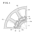
- Fig. 1 is an enlarged cross-sectional view of a portion of an electric motor according to a first embodiment disclosed here;
- Fig. 2 is a plan view of a portion of the electric motor according to the first embodiment
- Fig. 3 is a longitudinal section view illustrating a portion accommodating permanent magnets of a back yoke of a rotor of the electric motor according to the first embodiment
- Fig. 4 is a longitudinal section view illustrating a joint structure of the back yoke of the rotor according to the first embodiment
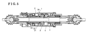
- Fig. 5 is a cross-sectional view of a main configuration of a rear wheel steering apparatus including the electric motor according to the first embodiment
- Fig. 6 is an enlarged cross-sectional view of a portion of the electric motor according to a modified example of the first embodiment
- Fig. 7 is an enlarged cross-sectional view of a portion of a rotor of an electric motor according to a second embodiment disclosed here;
- Fig. 8 is a plan view of a portion of the electric motor according to the second embodiment.
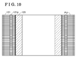
- Fig. 10 is a cross-sectional view taken along a line X-X in Fig. 8 and illustrating a joint structure of the back yoke of the rotor according to the second embodiment;
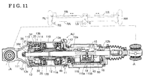
- Fig. 11 is a cross-sectional view of a main configuration of a rear wheel steering apparatus including the electric motor according to the second embodiment
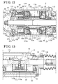
- Fig. 12 is an enlarged cross-sectional view of an actuator portion according to the second embodiment.
- Fig. 13 is an enlarged cross-sectional view of a controller portion according to the second embodiment.
- FIG. 5 illustrates an entire configuration of a rear wheel steering apparatus including an electric motor according to a first embodiment.
- a brushless motor 2 supported by a housing 1 is used as the electric motor.
- a hollow rotation shaft 21 serving as an output shaft of the brushless motor 2 is connected to a planetary gear train 3 so that an output of the brushless motor 2 (a rotation speed) decreases.
- An output side of the planetary gear train 3 is connected to a screw mechanism 4.
- a rod 5 meshed with the screw mechanism 4 and connected to rear wheels at opposing ends of the rod 5 is inserted into the hollow rotation shaft 21.
- the rod 5 is supported by the housing 1 to be non-rotatable and axially movable relative to the housing 1. Accordingly, a rotation driving force output via the planetary gear train 3 when the brushless motor 2 rotates is converted to an axial driving force of the rod 5 via the screw mechanism 4 so as to steer and operate the rear wheels.
- the brushless motor 2 includes a stator 24 and a rotor 20 that includes the hollow rotation shaft 21 supported by the housing 1 to be rotatable thereto, a cylindrically formed back yoke 22 fitted to an outer peripheral surface of the hollow rotation shaft 21 and integrally rotating with the hollow rotation shaft 21, and plural permanent magnets 23 arranged at the back yoke 22 at even intervals in a circumferential direction thereof.
- the rod 5 is inserted into the hollow rotation shaft 21 as illustrated by a chain double-dashed line in Figs. 1 and 2 to be brought to a state illustrated in Fig. 5 .
- a magnetic pole center PC is generated as illustrated in Fig. 1 .
- the permanent magnets 23 are accommodated within the back yoke 22 as illustrated in Figs. 1 to 3 .
- the permanent magnets 23 may be fixed to an outer peripheral surface of the back yoke 22.
- the back yoke 22 is formed by a lamination of plural annular plates made of nonmagnetic material. Concavo-convex portions 22p of the annular plates (steel plates) adjacent to one another are fitted so that the annular plates forming the back yoke 22 are joined to one another.
- application of hatching for the permanent magnets 23 is omitted for visibility.
- each of the projecting portions 22e projects towards the axial center of the hollow rotation shaft 21 from the inner peripheral surface of the back yoke 22 positioned at the circumferential center of each of the permanent magnets 23. Therefore, the magnetic path is formed from the back yoke 22 to the hollow rotation shaft 21 via each of the projecting portions 22e. A flux leakage is restrained to securely form the magnetic path passing through the hollow rotation shaft 21. Consequently, the performance of the brushless motor 2 may be improved.
- Fig. 6 illustrates a portion of members constituting the electric motor according to a modified example of the first embodiment.
- the substantially same members as those illustrated in Fig. 1 bear the same reference numerals.
- plural projecting portions 21e are formed at the hollow rotation shaft 21.
- each of the projecting portions 21e projects from the axial center of the hollow rotation shaft 21 towards the inner peripheral surface of the back yoke 22 positioned at the circumferential center portion of each of the permanent magnets 23.
- the projecting portions 21e extend in the axial direction of the hollow rotation shaft 21.
- the hollow rotation shaft 21 is press-fitted to the inner peripheral surface of the back yoke 22 via the projecting portions 21e.
- the magnetic path is formed from the back yoke 22 to the hollow rotation shaft 21 via each of the projecting portions 21e.
- the inner diameter (R1) of each of the projecting portions 121e is specified to be greater than the outer diameter (R0) of the hollow rotation shaft 120 and the distance (D) between at least the circumferential center of the inner peripheral surface of each of the projecting portions 121e and the axial center of the hollow rotation shaft 120 is specified to be equal to the outer diameter (R0) of the outer peripheral surface of the hollow rotation shaft 120. Therefore, in a case where the back yoke 121 is press-fitted to the hollow rotation shaft 120, the circumferential center of the inner peripheral surface of each of the projecting portions 121e makes contact with the outer peripheral surface of the hollow rotation shaft 120.
- grooves 121g, 121g are formed at respective circumferential sides of each of the projecting portions 121e so that the grooves 121g, 121g are parallel to the aforementioned projecting portion 121e. Therefore, even in a case where a large load is applied to the respective circumferential end portions of each of the projecting portions 121e, such load is released and escaped in directions where the grooves 121g, 121g are formed.
- One of the steel plates arranged at the uppermost portion in the lamination i.e., of the lamination steel
- a steel plate PU in Figs. 9 and 10 includes plural identification bores 121h formed to be recessed at even intervals in the circumferential direction as illustrated in Figs. 7 to 9 . Accordingly, the determination or identification of upper and lower surfaces of the back yoke 121 formed by the lamination steel is achievable. Not only an improved assembly performance is obtained but also the positioning at a time of magnetization is easily and securely performed. In this case, an additional processing such as an application of paint, for example, is not necessary for the identification of the upper and lower surfaces of the back yoke 121, which inhibits an increase of the number of processes.
- the rear wheel steering apparatus of the present embodiment constitutes a portion of a four-wheel steering system (4WS) for a vehicle, of which a front wheel steering apparatus including a known configuration is omitted in Figs. 11 to 13 .
- various types of suspension mechanisms are considered for supporting rear wheels of a vehicle.
- a suspension mechanism is configured as illustrated by a chain double-dashed line in Fig. 11 .
- an actuator unit AU constituting the rear wheel steering apparatus of the present embodiment is arranged between a support portion RS relative to a rear axle RA supporting rear wheels RL and RR and a link LS pivotally supported by the rear axle RA to rotate about a center C. Accordingly, a portion between the support portion RS and the link LS is driven to expand and contract, thereby steering the rear wheels RL and RR via tie rods TR and TR in association with the rotation of the link LS.
- the rod 12 is supported by the housing 11 in an axially movable manner, i.e., to perform a linear motion.
- On end portion of the actuator unit AU is connected to the link LS via a ball joint JL.
- the housing 11 is connected to the support portion RS via a ball joint JA.
- An actuator 13 drives the rod 12 so that the portion between the support portion RS of the rear axle RA and the link LS is driven in the expansion and contraction manner.
- the electric motor 13a constituting the actuator 13 is controlled by a controller 14 in a state where a rotation output of the electric motor 13a is reduced or decelerated by a deceleration mechanism 13b and is then converted to the linear motion of the rod 12 via a linear motion mechanism 13c.
- the electric motor 13a is constituted by a brushless motor.
- the housing 11 includes a first housing 11a that basically houses components of the actuator 13, for example, the electric motor 13a, and a second housing 11b that basically houses components of the controller 14, for example, an electronic circuit board 40.
- a connection cover 111 is connected to a cylindrical body 110 constituting the first housing 11a while a case 112 constituting the second housing 11b and including opening portions at upper and lower sides in a vertical direction and at both sides in an axial direction of the hollow rotation shaft 120 is connected to the cylindrical body 110.
- the connection cover 111 serves as a first connection member while the case 112 serves as a second connection member.
- the housing 11 is connected to the suspension mechanism via the connection cover 111 and the case 112.
- the actuator 13 is press-fitted and fixed within the cylindrical body 110 in a state where the coil 123 is wound on the stator 124.
- An output shaft of the electric motor 13a is formed by the hollow rotation shaft 120 that is rotatably supported by an inner diameter portion 25a of a motor cover 25 inserted into the cylindrical body 110 and formed in an annular form and by an annular groove 112a formed at the case 112 via bearings 25b and 112b respectively.
- the aforementioned back yoke 121 is press-fitted and fixed to an axially intermediate portion of the hollow rotation shaft 120.
- the permanent magnets 122 are arranged at even intervals in the circumferential direction of the back yoke 121.
- the deceleration mechanism 13b is constituted by a planetary gear mechanism 30.
- the planetary gear mechanism 30 includes a sun gear 31 serving as an external gear, a ring gear 33 serving as an internal gear, and a planetary gear 32 serving as an external gear.
- the sun gear 31 is integrally connected to the hollow rotation shaft 120 to be rotatable thereto.
- the ring gear 33 is fixed to a holder 34 serving as a cylindrical holding member.
- the planetary gear 32 is meshed with the sun gear 31 and the ring gear 33 to rotate around the sun gear 31.
- a nut member 36 serving as a carrier for rotatably supporting the planetary gear 32 via a pin 35 is rotatably supported by the holder 34 via a bearing 37.
- the bearing 37 serves as a ball bearing including an inner ring 37a fitted to the nut member 36 and an outer ring 37b is fitted to the holder 34.
- the bearing 37 is held by the nut member 36 by means of a spacer 37c in a C-shape.
- the holder 34 and the pin 35 are made of metal, for example, made of iron.
- the sun gear 31, the planetary gear 32, and the ring gear 33 are made of synthetic resin.
- the sun gear 31 is integrally formed at the hollow rotation shaft 120 made of metal.
- the ring gear 33 is supported by the holder 34 to be non-rotatable thereto.
- the holder 34 is supported by the cylindrical body 110 to be non-rotatable thereto.
- a snap ring 114 is held at an annular groove 110a formed within the cylindrical body 110.
- An annular-formed lock nut 113 is meshed with a screw portion of the cylindrical body 110 at one side where the deceleration mechanism 13b is formed (i.e., a left side in Fig.
- the nut member 36 and the rod 12 are arranged in a state where an external thread portion 12c formed by a trapezoidal screw at an outer peripheral surface of one end portion of the rod 12 over a predetermined axial length is meshed with an internal thread portion 36c formed at an inner peripheral surface of the nut member 36.
- the nut member 36 and the rod 12 constitute the linear motion mechanism 13c.
- a nut 12d is meshed with an end of the external thread portion 12c. Because the rod 12 is supported in the aforementioned manner, an axial load that may be applied to the rod 12 is absorbed by the cylindrical body 110 and the connection cover 111 via the nut member 36, the bearing 37, the holder 34, and the snap ring 114.
- the displacement detection device 115 includes a displacement sensor 115a constituted by a magnetic vector sensor, for example, and a permanent magnet 115b constituted by a neodymium magnet, for example.
- the displacement sensor 115a is supported by the electronic circuit board 40 while the permanent magnet 115b is held within the magnet block 50.
- the magnet block 50 includes a function for detecting an axial displacement of the rod 12 when the rod 12 performs the linear motion and a function for inhibiting the rotation of the rod 12.
- the actuator 13 of the present embodiment in a case where the hollow rotation shaft 120 is driven to rotate by the electric motor 13a, the rotation output of the electric motor 13a is reduced and decelerated by the deceleration mechanism 13b of the planetary gear mechanism 30 to thereby drive the nut member 36 to rotate. That is, the nut member 36 is connected to the deceleration mechanism 13b to rotate. The rod 12 is meshed with the deceleration mechanism 13b. Then, the rotary motion of the nut member 36 is converted to the linear motion of the rod 12 by the linear motion mechanism 13c. As a result, the portion between the support portion RS of the rear axle RA and the link LS is driven in the expansion and contraction manner to adjust a steering angle of the rear wheels.
- the stator 124 on which the coil 123 is wound is press-fitted within the cylindrical body 110 by a press-fitting device and is then fixed to a predetermined position as illustrated in Fig. 12 .
- the motor cover 25 is inserted into the cylindrical body 110 and the snap ring 114 is fixed to the annular groove 110a within the cylindrical body 110.
- the bearing 25b is press-fitted to the hollow rotation shaft 120 at which the sun gear 31 is integrally formed, and thereafter a first pressing member 122a made of resin for holding the permanent magnets 122 and the back yoke 121 are press-fitted to the hollow rotation shaft 120.
- the permanent magnets 122 are then accommodated within the back yoke 121, and magnetized in a sub-assembly state where a second pressing member 122b is press-fitted to the hollow rotation shaft 120.
- the aforementioned hollow rotation shaft 120 is inserted into a hollow portion of the stator 124 so that the bearing 25b is held in a state to be fitted to a hollow portion of the motor cover 25. Further, a support member 26 to which a plastic magnet 6b for a magnetic pole sensor 6 is fixedly attached is press-fitted to an end portion of the hollow rotation shaft 120.
- the case 112 is connected to an opening portion of the cylindrical body 110 facing the electric motor 13a (i.e., at a right side in Fig. 12 ) so that the case 112 and the cylindrical body 110 are connected to each other by a bolt.
- An outer ring of the bearing 112b is fitted to the annular groove 112a of the case 112.
- an inner ring of the bearing 112b is fitted to the hollow rotation shaft 120.
- the inner ring 37a of the bearing 37 is fitted to the nut member 36 to be held by the spacer 37c while the outer ring 37b of the bearing 37 is fitted to the holder 34.
- the ring gear 33 is attached to the holder 34 and the planetary gear 32 is supported by the nut member 36 by the pin 35.
- An engagement member 38 is then engaged with the pin 35.
- the external thread portion 12c of the rod 12 is meshed with the internal thread portion 36c of the nut member 36, and the nut 12d is meshed with the end portion of the external thread portion 12c to thereby obtain a sub-assembly.
- the plural identification bores 121h are formed at the uppermost steel plate of the lamination steel as illustrated in Fig. 8 .
- the upper and lower surfaces of the back yoke 121 may be determined and identified to thereby easily confirm the press-fitting direction of the back yoke 121 to the hollow rotation shaft 120.
- the positioning for magnetization is achievable by the plural identification bores 121h serving as a mark, which may lead to an easy and secure magnetizing operation.
Landscapes
- Engineering & Computer Science (AREA)
- Chemical & Material Sciences (AREA)
- Combustion & Propulsion (AREA)
- Transportation (AREA)
- Mechanical Engineering (AREA)
- Power Engineering (AREA)
- Power Steering Mechanism (AREA)
- Permanent Field Magnets Of Synchronous Machinery (AREA)
Applications Claiming Priority (2)
| Application Number | Priority Date | Filing Date | Title |
|---|---|---|---|
| JP2012201440A JP2014057456A (ja) | 2012-09-13 | 2012-09-13 | 電動モータのロータ |
| JP2013112520A JP6210365B2 (ja) | 2013-05-29 | 2013-05-29 | 電動モータのロータ、及び該ロータを備えた車両の後輪操舵装置 |
Publications (3)
| Publication Number | Publication Date |
|---|---|
| EP2709241A2 true EP2709241A2 (de) | 2014-03-19 |
| EP2709241A3 EP2709241A3 (de) | 2015-09-02 |
| EP2709241B1 EP2709241B1 (de) | 2020-07-29 |
Family
ID=49162033
Family Applications (1)
| Application Number | Title | Priority Date | Filing Date |
|---|---|---|---|
| EP13184171.0A Active EP2709241B1 (de) | 2012-09-13 | 2013-09-12 | Hinterradlenksystemvorrichtung für ein Fahrzeug mit einem Rotor |
Country Status (1)
| Country | Link |
|---|---|
| EP (1) | EP2709241B1 (de) |
Cited By (5)
| Publication number | Priority date | Publication date | Assignee | Title |
|---|---|---|---|---|
| EP2998202A1 (de) * | 2014-09-19 | 2016-03-23 | Aisin Seiki Kabushiki Kaisha | Hinterradlenkvorrichtung für ein fahrzeug |
| EP3553921A1 (de) * | 2018-04-10 | 2019-10-16 | SKF Motion Technologies AB | Betätigungszylinder mit rotorwelle zur lagerung von permanentmagneten |
| CN111355320A (zh) * | 2018-12-21 | 2020-06-30 | 株式会社三井高科技 | 叠片铁芯以及叠片铁芯的制造方法 |
| US10707716B2 (en) | 2017-11-20 | 2020-07-07 | Borgwarner Inc. | Stator core and stator slot closer |
| CN114448121A (zh) * | 2022-04-06 | 2022-05-06 | 江苏慧马科技有限公司 | 一种用于同步磁阻电机的转子叠片组 |
Citations (4)
| Publication number | Priority date | Publication date | Assignee | Title |
|---|---|---|---|---|
| JP2007014178A (ja) | 2005-07-04 | 2007-01-18 | Aisin Seiki Co Ltd | ロータ |
| JP2009113730A (ja) | 2007-11-08 | 2009-05-28 | Aisin Seiki Co Ltd | 車両の後輪操舵装置 |
| JP2012511465A (ja) | 2008-12-09 | 2012-05-24 | コンチネンタル・テベス・アーゲー・ウント・コンパニー・オーハーゲー | 特に後輪ステアリングシステム用ステアリング装置 |
| JP5098242B2 (ja) | 2006-07-26 | 2012-12-12 | アイシン精機株式会社 | 車輪操舵装置 |
Family Cites Families (6)
| Publication number | Priority date | Publication date | Assignee | Title |
|---|---|---|---|---|
| JP3028905B2 (ja) * | 1994-01-31 | 2000-04-04 | アイシン精機株式会社 | 後輪操舵アクチュエ−タ |
| US20060022541A1 (en) * | 2004-07-30 | 2006-02-02 | Raymond Ong | Rotor hub and assembly for a permanent magnet power electric machine |
| US20080042503A1 (en) * | 2006-08-15 | 2008-02-21 | Hartkorn Hans-Walter | Electric motor |
| DE102007006986B3 (de) * | 2007-02-07 | 2008-06-19 | Ima Materialforschung Und Anwendungstechnik Gmbh | Rotor für eine schnell laufende elektrische Maschine |
| US8536748B2 (en) * | 2008-11-11 | 2013-09-17 | Ford Global Technologies, Llc | Permanent magnet machine with different pole arc angles |
| DE102010063086A1 (de) * | 2009-12-21 | 2011-06-22 | Robert Bosch GmbH, 70469 | Rotor für eine elektrische Maschine |
-
2013
- 2013-09-12 EP EP13184171.0A patent/EP2709241B1/de active Active
Patent Citations (4)
| Publication number | Priority date | Publication date | Assignee | Title |
|---|---|---|---|---|
| JP2007014178A (ja) | 2005-07-04 | 2007-01-18 | Aisin Seiki Co Ltd | ロータ |
| JP5098242B2 (ja) | 2006-07-26 | 2012-12-12 | アイシン精機株式会社 | 車輪操舵装置 |
| JP2009113730A (ja) | 2007-11-08 | 2009-05-28 | Aisin Seiki Co Ltd | 車両の後輪操舵装置 |
| JP2012511465A (ja) | 2008-12-09 | 2012-05-24 | コンチネンタル・テベス・アーゲー・ウント・コンパニー・オーハーゲー | 特に後輪ステアリングシステム用ステアリング装置 |
Cited By (10)
| Publication number | Priority date | Publication date | Assignee | Title |
|---|---|---|---|---|
| EP2998202A1 (de) * | 2014-09-19 | 2016-03-23 | Aisin Seiki Kabushiki Kaisha | Hinterradlenkvorrichtung für ein fahrzeug |
| CN105438251A (zh) * | 2014-09-19 | 2016-03-30 | 爱信精机株式会社 | 车辆的后轮转向装置 |
| JP2016060393A (ja) * | 2014-09-19 | 2016-04-25 | アイシン精機株式会社 | 車両の後輪操舵装置 |
| US9550517B2 (en) | 2014-09-19 | 2017-01-24 | Aisin Seiki Kabushiki Kaisha | Rear wheel steering apparatus for vehicle |
| CN105438251B (zh) * | 2014-09-19 | 2019-01-11 | 爱信精机株式会社 | 车辆的后轮转向装置 |
| US10707716B2 (en) | 2017-11-20 | 2020-07-07 | Borgwarner Inc. | Stator core and stator slot closer |
| EP3553921A1 (de) * | 2018-04-10 | 2019-10-16 | SKF Motion Technologies AB | Betätigungszylinder mit rotorwelle zur lagerung von permanentmagneten |
| CN111355320A (zh) * | 2018-12-21 | 2020-06-30 | 株式会社三井高科技 | 叠片铁芯以及叠片铁芯的制造方法 |
| CN114448121A (zh) * | 2022-04-06 | 2022-05-06 | 江苏慧马科技有限公司 | 一种用于同步磁阻电机的转子叠片组 |
| CN114448121B (zh) * | 2022-04-06 | 2022-06-21 | 江苏慧马科技有限公司 | 一种用于同步磁阻电机的转子叠片组 |
Also Published As
| Publication number | Publication date |
|---|---|
| EP2709241A3 (de) | 2015-09-02 |
| EP2709241B1 (de) | 2020-07-29 |
Similar Documents
| Publication | Publication Date | Title |
|---|---|---|
| EP2709241B1 (de) | Hinterradlenksystemvorrichtung für ein Fahrzeug mit einem Rotor | |
| US8203245B2 (en) | Motor rotor, having magnet holding projections | |
| US9254868B2 (en) | Displacement detection apparatus for linear motion mechanism and rear wheel steering apparatus for vehicle including the same | |
| JP4726564B2 (ja) | 回転電機及び電動車椅子 | |
| WO2017138353A1 (ja) | ボールねじ装置およびこれを備える電動アクチュエータ | |
| EP2808229B1 (de) | Hinterradlenkvorrichtung für Fahrzeug | |
| EP2808231A1 (de) | Hinterradlenkvorrichtung für ein Fahrzeug | |
| JP6349627B2 (ja) | 直動機構の変位検知装置、及び該装置を備えた車両の後輪操舵装置 | |
| KR20120002938A (ko) | 액추에이터 | |
| JP5111863B2 (ja) | アキシャルギャップ型モータおよび電動パワーステアリング装置 | |
| EP3135944A1 (de) | Vorrichtung zur übertragung einer antriebskraft | |
| US20080129133A1 (en) | Electric Actuator | |
| JP6443958B1 (ja) | アウターロータ型モータ、および、電気自動車 | |
| JP6210365B2 (ja) | 電動モータのロータ、及び該ロータを備えた車両の後輪操舵装置 | |
| CN109417331B (zh) | 电动式直线移动促动器 | |
| JP6314660B2 (ja) | センサ実装基板、該基板を備えた変位検知装置、及び該装置を備えた車両の後輪操舵装置 | |
| WO2016129436A1 (ja) | 後輪転舵装置 | |
| JP5292953B2 (ja) | アキシャルギャップ型モータ | |
| KR101630116B1 (ko) | 자동차의 동력 보조 조향장치 | |
| WO2018047846A1 (ja) | 回転伝達装置 | |
| JP2005247171A (ja) | 車両の操舵装置 | |
| JP2001165271A (ja) | 直進・回転アクチュエータ | |
| JP7295432B2 (ja) | ステータ及び渦電流式減速装置の製造方法 | |
| JP2004328891A (ja) | 渦電流式減速装置 | |
| JP6716401B2 (ja) | 回転伝達装置 |
Legal Events
| Date | Code | Title | Description |
|---|---|---|---|
| PUAI | Public reference made under article 153(3) epc to a published international application that has entered the european phase |
Free format text: ORIGINAL CODE: 0009012 |
|
| AK | Designated contracting states |
Kind code of ref document: A2 Designated state(s): AL AT BE BG CH CY CZ DE DK EE ES FI FR GB GR HR HU IE IS IT LI LT LU LV MC MK MT NL NO PL PT RO RS SE SI SK SM TR |
|
| AX | Request for extension of the european patent |
Extension state: BA ME |
|
| PUAL | Search report despatched |
Free format text: ORIGINAL CODE: 0009013 |
|
| AK | Designated contracting states |
Kind code of ref document: A3 Designated state(s): AL AT BE BG CH CY CZ DE DK EE ES FI FR GB GR HR HU IE IS IT LI LT LU LV MC MK MT NL NO PL PT RO RS SE SI SK SM TR |
|
| AX | Request for extension of the european patent |
Extension state: BA ME |
|
| RIC1 | Information provided on ipc code assigned before grant |
Ipc: H02K 1/30 20060101ALI20150727BHEP Ipc: H02K 1/27 20060101AFI20150727BHEP Ipc: B62D 7/14 20060101ALI20150727BHEP |
|
| 17P | Request for examination filed |
Effective date: 20160301 |
|
| RBV | Designated contracting states (corrected) |
Designated state(s): AL AT BE BG CH CY CZ DE DK EE ES FI FR GB GR HR HU IE IS IT LI LT LU LV MC MK MT NL NO PL PT RO RS SE SI SK SM TR |
|
| GRAP | Despatch of communication of intention to grant a patent |
Free format text: ORIGINAL CODE: EPIDOSNIGR1 |
|
| STAA | Information on the status of an ep patent application or granted ep patent |
Free format text: STATUS: GRANT OF PATENT IS INTENDED |
|
| INTG | Intention to grant announced |
Effective date: 20190911 |
|
| RAP1 | Party data changed (applicant data changed or rights of an application transferred) |
Owner name: AISIN SEIKI KABUSHIKI KAISHA |
|
| GRAJ | Information related to disapproval of communication of intention to grant by the applicant or resumption of examination proceedings by the epo deleted |
Free format text: ORIGINAL CODE: EPIDOSDIGR1 |
|
| STAA | Information on the status of an ep patent application or granted ep patent |
Free format text: STATUS: REQUEST FOR EXAMINATION WAS MADE |
|
| GRAP | Despatch of communication of intention to grant a patent |
Free format text: ORIGINAL CODE: EPIDOSNIGR1 |
|
| STAA | Information on the status of an ep patent application or granted ep patent |
Free format text: STATUS: GRANT OF PATENT IS INTENDED |
|
| INTC | Intention to grant announced (deleted) | ||
| INTG | Intention to grant announced |
Effective date: 20200210 |
|
| GRAS | Grant fee paid |
Free format text: ORIGINAL CODE: EPIDOSNIGR3 |
|
| GRAA | (expected) grant |
Free format text: ORIGINAL CODE: 0009210 |
|
| STAA | Information on the status of an ep patent application or granted ep patent |
Free format text: STATUS: THE PATENT HAS BEEN GRANTED |
|
| AK | Designated contracting states |
Kind code of ref document: B1 Designated state(s): AL AT BE BG CH CY CZ DE DK EE ES FI FR GB GR HR HU IE IS IT LI LT LU LV MC MK MT NL NO PL PT RO RS SE SI SK SM TR |
|
| REG | Reference to a national code |
Ref country code: GB Ref legal event code: FG4D |
|
| REG | Reference to a national code |
Ref country code: CH Ref legal event code: EP |
|
| REG | Reference to a national code |
Ref country code: AT Ref legal event code: REF Ref document number: 1296933 Country of ref document: AT Kind code of ref document: T Effective date: 20200815 |
|
| REG | Reference to a national code |
Ref country code: IE Ref legal event code: FG4D |
|
| REG | Reference to a national code |
Ref country code: DE Ref legal event code: R096 Ref document number: 602013071065 Country of ref document: DE |
|
| REG | Reference to a national code |
Ref country code: LT Ref legal event code: MG4D |
|
| REG | Reference to a national code |
Ref country code: NL Ref legal event code: MP Effective date: 20200729 |
|
| REG | Reference to a national code |
Ref country code: AT Ref legal event code: MK05 Ref document number: 1296933 Country of ref document: AT Kind code of ref document: T Effective date: 20200729 |
|
| PG25 | Lapsed in a contracting state [announced via postgrant information from national office to epo] |
Ref country code: AT Free format text: LAPSE BECAUSE OF FAILURE TO SUBMIT A TRANSLATION OF THE DESCRIPTION OR TO PAY THE FEE WITHIN THE PRESCRIBED TIME-LIMIT Effective date: 20200729 Ref country code: ES Free format text: LAPSE BECAUSE OF FAILURE TO SUBMIT A TRANSLATION OF THE DESCRIPTION OR TO PAY THE FEE WITHIN THE PRESCRIBED TIME-LIMIT Effective date: 20200729 Ref country code: BG Free format text: LAPSE BECAUSE OF FAILURE TO SUBMIT A TRANSLATION OF THE DESCRIPTION OR TO PAY THE FEE WITHIN THE PRESCRIBED TIME-LIMIT Effective date: 20201029 Ref country code: NO Free format text: LAPSE BECAUSE OF FAILURE TO SUBMIT A TRANSLATION OF THE DESCRIPTION OR TO PAY THE FEE WITHIN THE PRESCRIBED TIME-LIMIT Effective date: 20201029 Ref country code: SE Free format text: LAPSE BECAUSE OF FAILURE TO SUBMIT A TRANSLATION OF THE DESCRIPTION OR TO PAY THE FEE WITHIN THE PRESCRIBED TIME-LIMIT Effective date: 20200729 Ref country code: PT Free format text: LAPSE BECAUSE OF FAILURE TO SUBMIT A TRANSLATION OF THE DESCRIPTION OR TO PAY THE FEE WITHIN THE PRESCRIBED TIME-LIMIT Effective date: 20201130 Ref country code: HR Free format text: LAPSE BECAUSE OF FAILURE TO SUBMIT A TRANSLATION OF THE DESCRIPTION OR TO PAY THE FEE WITHIN THE PRESCRIBED TIME-LIMIT Effective date: 20200729 Ref country code: LT Free format text: LAPSE BECAUSE OF FAILURE TO SUBMIT A TRANSLATION OF THE DESCRIPTION OR TO PAY THE FEE WITHIN THE PRESCRIBED TIME-LIMIT Effective date: 20200729 Ref country code: GR Free format text: LAPSE BECAUSE OF FAILURE TO SUBMIT A TRANSLATION OF THE DESCRIPTION OR TO PAY THE FEE WITHIN THE PRESCRIBED TIME-LIMIT Effective date: 20201030 Ref country code: FI Free format text: LAPSE BECAUSE OF FAILURE TO SUBMIT A TRANSLATION OF THE DESCRIPTION OR TO PAY THE FEE WITHIN THE PRESCRIBED TIME-LIMIT Effective date: 20200729 |
|
| PG25 | Lapsed in a contracting state [announced via postgrant information from national office to epo] |
Ref country code: IS Free format text: LAPSE BECAUSE OF FAILURE TO SUBMIT A TRANSLATION OF THE DESCRIPTION OR TO PAY THE FEE WITHIN THE PRESCRIBED TIME-LIMIT Effective date: 20201129 Ref country code: LV Free format text: LAPSE BECAUSE OF FAILURE TO SUBMIT A TRANSLATION OF THE DESCRIPTION OR TO PAY THE FEE WITHIN THE PRESCRIBED TIME-LIMIT Effective date: 20200729 Ref country code: RS Free format text: LAPSE BECAUSE OF FAILURE TO SUBMIT A TRANSLATION OF THE DESCRIPTION OR TO PAY THE FEE WITHIN THE PRESCRIBED TIME-LIMIT Effective date: 20200729 Ref country code: PL Free format text: LAPSE BECAUSE OF FAILURE TO SUBMIT A TRANSLATION OF THE DESCRIPTION OR TO PAY THE FEE WITHIN THE PRESCRIBED TIME-LIMIT Effective date: 20200729 |
|
| PG25 | Lapsed in a contracting state [announced via postgrant information from national office to epo] |
Ref country code: NL Free format text: LAPSE BECAUSE OF FAILURE TO SUBMIT A TRANSLATION OF THE DESCRIPTION OR TO PAY THE FEE WITHIN THE PRESCRIBED TIME-LIMIT Effective date: 20200729 |
|
| PG25 | Lapsed in a contracting state [announced via postgrant information from national office to epo] |
Ref country code: EE Free format text: LAPSE BECAUSE OF FAILURE TO SUBMIT A TRANSLATION OF THE DESCRIPTION OR TO PAY THE FEE WITHIN THE PRESCRIBED TIME-LIMIT Effective date: 20200729 Ref country code: CZ Free format text: LAPSE BECAUSE OF FAILURE TO SUBMIT A TRANSLATION OF THE DESCRIPTION OR TO PAY THE FEE WITHIN THE PRESCRIBED TIME-LIMIT Effective date: 20200729 Ref country code: DK Free format text: LAPSE BECAUSE OF FAILURE TO SUBMIT A TRANSLATION OF THE DESCRIPTION OR TO PAY THE FEE WITHIN THE PRESCRIBED TIME-LIMIT Effective date: 20200729 Ref country code: IT Free format text: LAPSE BECAUSE OF FAILURE TO SUBMIT A TRANSLATION OF THE DESCRIPTION OR TO PAY THE FEE WITHIN THE PRESCRIBED TIME-LIMIT Effective date: 20200729 Ref country code: RO Free format text: LAPSE BECAUSE OF FAILURE TO SUBMIT A TRANSLATION OF THE DESCRIPTION OR TO PAY THE FEE WITHIN THE PRESCRIBED TIME-LIMIT Effective date: 20200729 Ref country code: SM Free format text: LAPSE BECAUSE OF FAILURE TO SUBMIT A TRANSLATION OF THE DESCRIPTION OR TO PAY THE FEE WITHIN THE PRESCRIBED TIME-LIMIT Effective date: 20200729 Ref country code: MC Free format text: LAPSE BECAUSE OF FAILURE TO SUBMIT A TRANSLATION OF THE DESCRIPTION OR TO PAY THE FEE WITHIN THE PRESCRIBED TIME-LIMIT Effective date: 20200729 |
|
| REG | Reference to a national code |
Ref country code: DE Ref legal event code: R097 Ref document number: 602013071065 Country of ref document: DE Ref country code: CH Ref legal event code: PL |
|
| PG25 | Lapsed in a contracting state [announced via postgrant information from national office to epo] |
Ref country code: AL Free format text: LAPSE BECAUSE OF FAILURE TO SUBMIT A TRANSLATION OF THE DESCRIPTION OR TO PAY THE FEE WITHIN THE PRESCRIBED TIME-LIMIT Effective date: 20200729 |
|
| PLBE | No opposition filed within time limit |
Free format text: ORIGINAL CODE: 0009261 |
|
| STAA | Information on the status of an ep patent application or granted ep patent |
Free format text: STATUS: NO OPPOSITION FILED WITHIN TIME LIMIT |
|
| REG | Reference to a national code |
Ref country code: BE Ref legal event code: MM Effective date: 20200930 |
|
| GBPC | Gb: european patent ceased through non-payment of renewal fee |
Effective date: 20201029 |
|
| PG25 | Lapsed in a contracting state [announced via postgrant information from national office to epo] |
Ref country code: SK Free format text: LAPSE BECAUSE OF FAILURE TO SUBMIT A TRANSLATION OF THE DESCRIPTION OR TO PAY THE FEE WITHIN THE PRESCRIBED TIME-LIMIT Effective date: 20200729 Ref country code: LU Free format text: LAPSE BECAUSE OF NON-PAYMENT OF DUE FEES Effective date: 20200912 |
|
| 26N | No opposition filed |
Effective date: 20210430 |
|
| PG25 | Lapsed in a contracting state [announced via postgrant information from national office to epo] |
Ref country code: SI Free format text: LAPSE BECAUSE OF FAILURE TO SUBMIT A TRANSLATION OF THE DESCRIPTION OR TO PAY THE FEE WITHIN THE PRESCRIBED TIME-LIMIT Effective date: 20200729 Ref country code: LI Free format text: LAPSE BECAUSE OF NON-PAYMENT OF DUE FEES Effective date: 20200930 Ref country code: GB Free format text: LAPSE BECAUSE OF NON-PAYMENT OF DUE FEES Effective date: 20201029 Ref country code: IE Free format text: LAPSE BECAUSE OF NON-PAYMENT OF DUE FEES Effective date: 20200912 Ref country code: BE Free format text: LAPSE BECAUSE OF NON-PAYMENT OF DUE FEES Effective date: 20200930 Ref country code: CH Free format text: LAPSE BECAUSE OF NON-PAYMENT OF DUE FEES Effective date: 20200930 |
|
| PG25 | Lapsed in a contracting state [announced via postgrant information from national office to epo] |
Ref country code: TR Free format text: LAPSE BECAUSE OF FAILURE TO SUBMIT A TRANSLATION OF THE DESCRIPTION OR TO PAY THE FEE WITHIN THE PRESCRIBED TIME-LIMIT Effective date: 20200729 Ref country code: MT Free format text: LAPSE BECAUSE OF FAILURE TO SUBMIT A TRANSLATION OF THE DESCRIPTION OR TO PAY THE FEE WITHIN THE PRESCRIBED TIME-LIMIT Effective date: 20200729 Ref country code: CY Free format text: LAPSE BECAUSE OF FAILURE TO SUBMIT A TRANSLATION OF THE DESCRIPTION OR TO PAY THE FEE WITHIN THE PRESCRIBED TIME-LIMIT Effective date: 20200729 |
|
| PG25 | Lapsed in a contracting state [announced via postgrant information from national office to epo] |
Ref country code: MK Free format text: LAPSE BECAUSE OF FAILURE TO SUBMIT A TRANSLATION OF THE DESCRIPTION OR TO PAY THE FEE WITHIN THE PRESCRIBED TIME-LIMIT Effective date: 20200729 |
|
| PGFP | Annual fee paid to national office [announced via postgrant information from national office to epo] |
Ref country code: DE Payment date: 20250730 Year of fee payment: 13 |
|
| PGFP | Annual fee paid to national office [announced via postgrant information from national office to epo] |
Ref country code: FR Payment date: 20250808 Year of fee payment: 13 |