EP3553921A1 - Betätigungszylinder mit rotorwelle zur lagerung von permanentmagneten - Google Patents
Betätigungszylinder mit rotorwelle zur lagerung von permanentmagneten Download PDFInfo
- Publication number
- EP3553921A1 EP3553921A1 EP18166511.8A EP18166511A EP3553921A1 EP 3553921 A1 EP3553921 A1 EP 3553921A1 EP 18166511 A EP18166511 A EP 18166511A EP 3553921 A1 EP3553921 A1 EP 3553921A1
- Authority
- EP
- European Patent Office
- Prior art keywords
- rotor shaft
- actuating cylinder
- screw
- sleeve
- housing
- Prior art date
- Legal status (The legal status is an assumption and is not a legal conclusion. Google has not performed a legal analysis and makes no representation as to the accuracy of the status listed.)
- Withdrawn
Links
- 238000005096 rolling process Methods 0.000 claims abstract description 12
- 238000012423 maintenance Methods 0.000 description 2
- 238000006243 chemical reaction Methods 0.000 description 1
- 230000003247 decreasing effect Effects 0.000 description 1
- 230000007547 defect Effects 0.000 description 1
- 230000006866 deterioration Effects 0.000 description 1
- 230000007257 malfunction Effects 0.000 description 1
- 125000006850 spacer group Chemical group 0.000 description 1
Images

Classifications
-
- H—ELECTRICITY
- H02—GENERATION; CONVERSION OR DISTRIBUTION OF ELECTRIC POWER
- H02K—DYNAMO-ELECTRIC MACHINES
- H02K1/00—Details of the magnetic circuit
- H02K1/06—Details of the magnetic circuit characterised by the shape, form or construction
- H02K1/22—Rotating parts of the magnetic circuit
- H02K1/27—Rotor cores with permanent magnets
- H02K1/2706—Inner rotors
- H02K1/272—Inner rotors the magnetisation axis of the magnets being perpendicular to the rotor axis
- H02K1/274—Inner rotors the magnetisation axis of the magnets being perpendicular to the rotor axis the rotor consisting of two or more circumferentially positioned magnets
- H02K1/2753—Inner rotors the magnetisation axis of the magnets being perpendicular to the rotor axis the rotor consisting of two or more circumferentially positioned magnets the rotor consisting of magnets or groups of magnets arranged with alternating polarity
- H02K1/278—Surface mounted magnets; Inset magnets
-
- H—ELECTRICITY
- H02—GENERATION; CONVERSION OR DISTRIBUTION OF ELECTRIC POWER
- H02K—DYNAMO-ELECTRIC MACHINES
- H02K1/00—Details of the magnetic circuit
- H02K1/06—Details of the magnetic circuit characterised by the shape, form or construction
- H02K1/22—Rotating parts of the magnetic circuit
- H02K1/28—Means for mounting or fastening rotating magnetic parts on to, or to, the rotor structures
- H02K1/30—Means for mounting or fastening rotating magnetic parts on to, or to, the rotor structures using intermediate parts, e.g. spiders
-
- F—MECHANICAL ENGINEERING; LIGHTING; HEATING; WEAPONS; BLASTING
- F16—ENGINEERING ELEMENTS AND UNITS; GENERAL MEASURES FOR PRODUCING AND MAINTAINING EFFECTIVE FUNCTIONING OF MACHINES OR INSTALLATIONS; THERMAL INSULATION IN GENERAL
- F16H—GEARING
- F16H25/00—Gearings comprising primarily only cams, cam-followers and screw-and-nut mechanisms
- F16H25/18—Gearings comprising primarily only cams, cam-followers and screw-and-nut mechanisms for conveying or interconverting oscillating or reciprocating motions
- F16H25/20—Screw mechanisms
- F16H2025/2062—Arrangements for driving the actuator
- F16H2025/2075—Coaxial drive motors
- F16H2025/2078—Coaxial drive motors the rotor being integrated with the nut or screw body
-
- F—MECHANICAL ENGINEERING; LIGHTING; HEATING; WEAPONS; BLASTING
- F16—ENGINEERING ELEMENTS AND UNITS; GENERAL MEASURES FOR PRODUCING AND MAINTAINING EFFECTIVE FUNCTIONING OF MACHINES OR INSTALLATIONS; THERMAL INSULATION IN GENERAL
- F16H—GEARING
- F16H25/00—Gearings comprising primarily only cams, cam-followers and screw-and-nut mechanisms
- F16H25/18—Gearings comprising primarily only cams, cam-followers and screw-and-nut mechanisms for conveying or interconverting oscillating or reciprocating motions
- F16H25/20—Screw mechanisms
- F16H25/22—Screw mechanisms with balls, rollers, or similar members between the co-operating parts; Elements essential to the use of such members
- F16H25/2204—Screw mechanisms with balls, rollers, or similar members between the co-operating parts; Elements essential to the use of such members with balls
-
- F—MECHANICAL ENGINEERING; LIGHTING; HEATING; WEAPONS; BLASTING
- F16—ENGINEERING ELEMENTS AND UNITS; GENERAL MEASURES FOR PRODUCING AND MAINTAINING EFFECTIVE FUNCTIONING OF MACHINES OR INSTALLATIONS; THERMAL INSULATION IN GENERAL
- F16H—GEARING
- F16H25/00—Gearings comprising primarily only cams, cam-followers and screw-and-nut mechanisms
- F16H25/18—Gearings comprising primarily only cams, cam-followers and screw-and-nut mechanisms for conveying or interconverting oscillating or reciprocating motions
- F16H25/20—Screw mechanisms
- F16H25/22—Screw mechanisms with balls, rollers, or similar members between the co-operating parts; Elements essential to the use of such members
- F16H25/2247—Screw mechanisms with balls, rollers, or similar members between the co-operating parts; Elements essential to the use of such members with rollers
- F16H25/2252—Planetary rollers between nut and screw
-
- H—ELECTRICITY
- H02—GENERATION; CONVERSION OR DISTRIBUTION OF ELECTRIC POWER
- H02K—DYNAMO-ELECTRIC MACHINES
- H02K7/00—Arrangements for handling mechanical energy structurally associated with dynamo-electric machines, e.g. structural association with mechanical driving motors or auxiliary dynamo-electric machines
- H02K7/06—Means for converting reciprocating motion into rotary motion or vice versa
Definitions
- the invention relates to the field of actuating cylinders, in particular the field of compact electromechanical cylinders with integrated electric motor.
- An electromechanical actuating cylinder generally comprises a housing, an actuation rod mounted so as to be movable longitudinally relative to the housing, an electric motor having a stator and a rotor, a mechanism for converting the rotational movement of the rotor shaft of the motor into a linear movement in translation of the actuation rod, and at least one bearing for guiding in rotation and supporting the rotor shaft with respect to the housing.
- Such mechanism can be a screw mechanism including a screw provided with an external thread, a nut disposed around the screw and having an internal thread, and a plurality of rolling elements engaged with the internal and external threads.
- Said elements can be rollers and the mechanism is of roller screw type, or balls and the mechanism is of ball screw type.
- the nut is driven in rotational movement by the rotor of the electric motor, the screw having then a translating movement by the intermediate of the rolling elements. Said screw is connected to the rod.
- the electromechanical cylinder further comprises bearings arranged between the nut and the housing.
- the rotor of electric motor comprises a rotor shaft and a plurality of permanent magnets supported by said rotor shaft.
- the rotor shaft is advantageously the nut of the inverted planetary screw mechanism.
- the permanent magnets are generally directly glued onto an outer surface of the rotor shaft.
- the rotor shaft has to be extracted and replaced in case of deterioration or malfunction of the permanent magnets. These are expensive operations.
- a complete rotor shaft with glued magnets and of given dimensions is only dedicated to a specific actuating cylinder. It is desirable to provide a modular design of actuating cylinder with some standardized components.
- the aim of the invention is to solve the above difficulties.
- an actuating cylinder comprising a housing; an actuation rod mounted to be movable longitudinally relative to the housing; an electric motor provided with a stator, and a rotor having a rotating rotor shaft and permanent magnets supported by the said rotor shaft; a screw mechanism including a screw provided with an external thread and connected to the actuation rod, the rotor shaft being disposed around the screw and having an internal thread, and a plurality of rolling elements engaged with the internal and external threads, the rotational movement of the rotor shaft being converted into a linear movement in translation of the screw and of the actuation rod.
- the permanent magnets are fixed to an outer surface of a sleeve, said sleeve being fixed onto an outer surface of the rotor shaft.
- such an actuating may incorporate one or several of the following features:
- a compact electromechanical actuating cylinder extends along a longitudinal axis X-X'.
- the actuating cylinder 10 comprises a housing 12, an actuation rod 14 movable axially and coaxially to the axis X-X', an electric motor 16, and an inverted planetary roller screw mechanism 18 disposed inside the housing 12.
- the screw mechanism 18 is disposed radially between the electric motor 16 and the actuation rod 14.
- the mechanism 18 allows the conversion of rotation movement of the electric motor 16 into a linear movement in translation of the actuation rod 14 along the axis X-X'.
- the electric motor 16 and the screw mechanism 18 are housed entirely within the housing 12.
- the actuation rod 14 extends through the housing 12 and protrudes axially to the outside.
- the housing 12 comprises a tubular main body 12-1 having a bore 13, a front cover 12-2 and a rear cover 12-3.
- the said covers are each fixed at one end of the main body 12-1.
- the electric motor 16 comprises a stator 20 fixed on the housing 12, and a rotor 22.
- the stator 20 is fixed in the bore 13 of main body 12-1 of housing 12.
- the bore 13 is advantageously stepped and comprises an inwardly radially projecting shoulder 13-1, the stator being in axial abutment against said shoulder 13-1 towards a front axial direction.
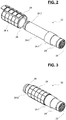
- the rotor 22 is provided with a tubular rotor shaft 24, a sleeve 26 and a plurality of permanent magnets 28 supported by said sleeve 26.
- the sleeve 26 comprises an outer cylindrical surface 26-1, and a cylindrical bore 26-2.
- the permanent magnets 28 are fixed to the outer cylindrical surface 26-1 of tubular sleeve 26.
- the permanent magnets 28 are glued to said sleeve 26.
- the tubular sleeve 26 is coaxial with the rotor shaft 24, and is mounted around an outer cylindrical surface 24-2 of said rotor shaft 24.
- the cylindrical bore 26-2 of sleeve 26 is press fitted onto the outer cylindrical surface 24-2 of rotor shaft.
- the sleeve 26 is glued onto the rotor shaft 24, or may be fixed by any other suitable means.
- the outer surface of rotor shaft 24 is stepped and comprises an outwardly projecting shoulder 24-1.
- the sleeve 26 is in axial abutment against the said shoulder 24-1 towards a front axial direction.
- the shoulder 24-1 permits to precisely position the sleeve 26 with permanent magnets 28 onto the rotor shaft 24 with respect to the stator 20 of electric motor 16.
- the sleeve 26 with the permanent magnets 28 can be easily extracted and replaced in case of defect, the rotor shaft 24 being kept.
- the replaced parts are then less expensive than a complete rotor shaft.
- Another advantage of the invention is that a standardized sleeve with magnets can be provided to a plurality of rotor shaft lengths. Such sleeve is assembled onto a particular rotor shaft on request only. This will participate to decrease the number of components on stock. Even if an intermediate part is added, the global costs are decreased.
- the rotor shaft 24 extends axially on either side of the stator 20.
- the electric motor 16 can be of the brushless type, or alternatively of any other suitable type.
- the actuating cylinder 10 also comprises two front rolling bearings 30, 32 and one rear rolling bearing 34.
- the bearings 30, 32, 34 are each of ball type.
- the bearing may be of any other suitable types, for example with tapered rollers or cylindrical rollers.
- the inverted planetary roller screw mechanism 18 comprises a screw 40, which is coaxial and connected to a second end 14-2 of the actuation rod 14.
- the rotor shaft 24 is of tubular shape, coaxial with the screw 40 and is disposed around said screw 40.
- the screw 40 comprises an external thread 41
- the rotor shaft 24 comprises an internal thread 25 of which the inner diameter is greater than the outer diameter of the external thread 41 of screw 40.
- the screw mechanism 18 further comprises a plurality of rollers 42 having each an external thread (not referenced) which is engaged in the external and internal threads 41, 25 of the screw 40 and the rotor shaft 24, respectively.
- the rollers 42 are identical to one another and are distributed uniformly around the screw 40.
- Each roller 42 extends along an axis parallel to the screw axis.
- each roller 42 comprises, at each end (not referenced), an outer toothing engaged with a synchronization toothing of the screw, and a journal extending axially to the outside from the toothing and housed in a recess in one of the spacer rings 44, 46 mounted around said screw 40.
- the rolling elements are balls engaged in external and internal threads of screw and rotor shaft, respectively.
- the actuation rod 14 is connected to the screw 40 of the screw mechanism 18.
- the rotation of the rotor shaft 24 of the electric motor 16 is converted into a translation of the screw 40 and of the actuation rod 14 along the axis X-X'.
Landscapes
- Engineering & Computer Science (AREA)
- Power Engineering (AREA)
- Connection Of Motors, Electrical Generators, Mechanical Devices, And The Like (AREA)
Priority Applications (1)
| Application Number | Priority Date | Filing Date | Title |
|---|---|---|---|
| EP18166511.8A EP3553921A1 (de) | 2018-04-10 | 2018-04-10 | Betätigungszylinder mit rotorwelle zur lagerung von permanentmagneten |
Applications Claiming Priority (1)
| Application Number | Priority Date | Filing Date | Title |
|---|---|---|---|
| EP18166511.8A EP3553921A1 (de) | 2018-04-10 | 2018-04-10 | Betätigungszylinder mit rotorwelle zur lagerung von permanentmagneten |
Publications (1)
| Publication Number | Publication Date |
|---|---|
| EP3553921A1 true EP3553921A1 (de) | 2019-10-16 |
Family
ID=61965765
Family Applications (1)
| Application Number | Title | Priority Date | Filing Date |
|---|---|---|---|
| EP18166511.8A Withdrawn EP3553921A1 (de) | 2018-04-10 | 2018-04-10 | Betätigungszylinder mit rotorwelle zur lagerung von permanentmagneten |
Country Status (1)
| Country | Link |
|---|---|
| EP (1) | EP3553921A1 (de) |
Citations (4)
| Publication number | Priority date | Publication date | Assignee | Title |
|---|---|---|---|---|
| EP1735895A1 (de) * | 2004-03-31 | 2006-12-27 | Danaher Motion Stockholm AB | Elektrisches betätigungsglied |
| EP1900081A1 (de) * | 2005-05-31 | 2008-03-19 | The Boeing Company | Elektromechanische linear-aktoren mit direktantrieb |
| EP2709241A2 (de) * | 2012-09-13 | 2014-03-19 | Aisin Seiki Kabushiki Kaisha | Rotor eines Elektromotors und Hinterradlenksystemvorrichtung für ein Fahrzeug mit einem Rotor |
| WO2015156706A2 (en) * | 2015-05-08 | 2015-10-15 | Zakrytoe Aktsionernoe Obschestvo "Diakont" | Linear electromechanical actuator |
-
2018
- 2018-04-10 EP EP18166511.8A patent/EP3553921A1/de not_active Withdrawn
Patent Citations (4)
| Publication number | Priority date | Publication date | Assignee | Title |
|---|---|---|---|---|
| EP1735895A1 (de) * | 2004-03-31 | 2006-12-27 | Danaher Motion Stockholm AB | Elektrisches betätigungsglied |
| EP1900081A1 (de) * | 2005-05-31 | 2008-03-19 | The Boeing Company | Elektromechanische linear-aktoren mit direktantrieb |
| EP2709241A2 (de) * | 2012-09-13 | 2014-03-19 | Aisin Seiki Kabushiki Kaisha | Rotor eines Elektromotors und Hinterradlenksystemvorrichtung für ein Fahrzeug mit einem Rotor |
| WO2015156706A2 (en) * | 2015-05-08 | 2015-10-15 | Zakrytoe Aktsionernoe Obschestvo "Diakont" | Linear electromechanical actuator |
Similar Documents
| Publication | Publication Date | Title |
|---|---|---|
| EP3553342A1 (de) | Betätigungszylinder mit lastsensor | |
| US8978497B2 (en) | Linear actuator with anti-rotation mechanism | |
| US8314519B2 (en) | Electromechanical linear actuator | |
| KR102334152B1 (ko) | 유성 롤러 스핀들을 구비한 액추에이터 | |
| EP2852517B1 (de) | Lageranordnung in einem axialantrieb | |
| CN1114770C (zh) | 具有小型齿轮减速机构的致动器 | |
| KR100597288B1 (ko) | 용접장치의 구동장치 | |
| US11561142B2 (en) | Electromechanical actuator with integrated force sensor | |
| EP1939019B1 (de) | Teleskopischer Stellantrieb | |
| US5899114A (en) | Differential ball screw and nut assembly and method of obtaining relative linear motion differentially | |
| CN106936260A (zh) | 机电式驱动缸 | |
| US10090730B2 (en) | Linear actuator | |
| US8001861B2 (en) | High force electro-mechanical actuator | |
| EP3701147B1 (de) | Verdichteranordnung zum betreiben einer druckluftversorgungsanlage, druckluftversorgungsanlage, fahrzeug | |
| KR102301346B1 (ko) | 스핀들 구동 유닛 | |
| EP2932131A2 (de) | Scheibenbremse mit einer feststellbremse, mechanische schubvorrichtung und verfahren zur montage | |
| EP3630593A1 (de) | Antriebseinheit für ein fahrrad | |
| US12181027B2 (en) | Electromechanical linear actuator | |
| US20220024435A1 (en) | Electromechanical brake pressure generator including spindle drive unit, braking system | |
| US7364420B2 (en) | Rotary press for making tablets | |
| EP1917459B1 (de) | Rotations-/linearbewegungsumwandlungsmechanismus | |
| US7474025B1 (en) | Main shaft clearance eliminating structure for a direct drive torque motor | |
| EP2334450B1 (de) | Elektromechanischer aktor für abkantpressen | |
| CN109826844B (zh) | 一种旋转气缸 | |
| US12320411B2 (en) | Electromechanical linear actuator with hollow shaft motor |
Legal Events
| Date | Code | Title | Description |
|---|---|---|---|
| PUAI | Public reference made under article 153(3) epc to a published international application that has entered the european phase |
Free format text: ORIGINAL CODE: 0009012 |
|
| STAA | Information on the status of an ep patent application or granted ep patent |
Free format text: STATUS: THE APPLICATION HAS BEEN PUBLISHED |
|
| AK | Designated contracting states |
Kind code of ref document: A1 Designated state(s): AL AT BE BG CH CY CZ DE DK EE ES FI FR GB GR HR HU IE IS IT LI LT LU LV MC MK MT NL NO PL PT RO RS SE SI SK SM TR |
|
| AX | Request for extension of the european patent |
Extension state: BA ME |
|
| STAA | Information on the status of an ep patent application or granted ep patent |
Free format text: STATUS: THE APPLICATION IS DEEMED TO BE WITHDRAWN |
|
| 18D | Application deemed to be withdrawn |
Effective date: 20200603 |