EP2709382A2 - Flacher lautsprecher mit einem schwingspulenfilm mit einer mehrschichtigen leiterplatte - Google Patents
Flacher lautsprecher mit einem schwingspulenfilm mit einer mehrschichtigen leiterplatte Download PDFInfo
- Publication number
- EP2709382A2 EP2709382A2 EP12781858.1A EP12781858A EP2709382A2 EP 2709382 A2 EP2709382 A2 EP 2709382A2 EP 12781858 A EP12781858 A EP 12781858A EP 2709382 A2 EP2709382 A2 EP 2709382A2
- Authority
- EP
- European Patent Office
- Prior art keywords
- voice coil
- layer
- layers
- pcb
- films
- Prior art date
- Legal status (The legal status is an assumption and is not a legal conclusion. Google has not performed a legal analysis and makes no representation as to the accuracy of the status listed.)
- Withdrawn
Links
Images


Classifications
-
- H—ELECTRICITY
- H04—ELECTRIC COMMUNICATION TECHNIQUE
- H04R—LOUDSPEAKERS, MICROPHONES, GRAMOPHONE PICK-UPS OR LIKE ACOUSTIC ELECTROMECHANICAL TRANSDUCERS; ELECTRIC HEARING AIDS; PUBLIC ADDRESS SYSTEMS
- H04R9/00—Transducers of moving-coil, moving-strip, or moving-wire type
- H04R9/02—Details
- H04R9/04—Construction, mounting, or centering of coil
-
- H—ELECTRICITY
- H04—ELECTRIC COMMUNICATION TECHNIQUE
- H04R—LOUDSPEAKERS, MICROPHONES, GRAMOPHONE PICK-UPS OR LIKE ACOUSTIC ELECTROMECHANICAL TRANSDUCERS; ELECTRIC HEARING AIDS; PUBLIC ADDRESS SYSTEMS
- H04R1/00—Details of transducers, loudspeakers or microphones
-
- H—ELECTRICITY
- H04—ELECTRIC COMMUNICATION TECHNIQUE
- H04R—LOUDSPEAKERS, MICROPHONES, GRAMOPHONE PICK-UPS OR LIKE ACOUSTIC ELECTROMECHANICAL TRANSDUCERS; ELECTRIC HEARING AIDS; PUBLIC ADDRESS SYSTEMS
- H04R9/00—Transducers of moving-coil, moving-strip, or moving-wire type
- H04R9/02—Details
- H04R9/04—Construction, mounting, or centering of coil
- H04R9/046—Construction
- H04R9/047—Construction in which the windings of the moving coil lay in the same plane
-
- H—ELECTRICITY
- H05—ELECTRIC TECHNIQUES NOT OTHERWISE PROVIDED FOR
- H05K—PRINTED CIRCUITS; CASINGS OR CONSTRUCTIONAL DETAILS OF ELECTRIC APPARATUS; MANUFACTURE OF ASSEMBLAGES OF ELECTRICAL COMPONENTS
- H05K3/00—Apparatus or processes for manufacturing printed circuits
- H05K3/46—Manufacturing multilayer circuits
-
- H—ELECTRICITY
- H04—ELECTRIC COMMUNICATION TECHNIQUE
- H04R—LOUDSPEAKERS, MICROPHONES, GRAMOPHONE PICK-UPS OR LIKE ACOUSTIC ELECTROMECHANICAL TRANSDUCERS; ELECTRIC HEARING AIDS; PUBLIC ADDRESS SYSTEMS
- H04R2209/00—Details of transducers of the moving-coil, moving-strip, or moving-wire type covered by H04R9/00 but not provided for in any of its subgroups
- H04R2209/041—Voice coil arrangements comprising more than one voice coil unit on the same bobbin
-
- H—ELECTRICITY
- H04—ELECTRIC COMMUNICATION TECHNIQUE
- H04R—LOUDSPEAKERS, MICROPHONES, GRAMOPHONE PICK-UPS OR LIKE ACOUSTIC ELECTROMECHANICAL TRANSDUCERS; ELECTRIC HEARING AIDS; PUBLIC ADDRESS SYSTEMS
- H04R7/00—Diaphragms for electromechanical transducers; Cones
- H04R7/02—Diaphragms for electromechanical transducers; Cones characterised by the construction
- H04R7/04—Plane diaphragms
Definitions
- the present invention relates to a flat type speaker and, more particularly, to a flat type speaker having multi-layer PCB pattern voice coil films, which has been implemented to increase induced electromotive force through control of the impedance of multi-layer voice coil films.
- a voice coil plate used in a flat type speaker is wound in an elliptical form and print-patterned on one side or both sides of a coil base of a plate form.
- the voice coil plate When current flows through a voice coil, the voice coil plate generates a magnetic field that is expanded and contracted around the voice coil in the same frequency as that of an audio signal by means of the flowing current. Since the magnetic field generated from the magnets within the speaker unit is applied to the voice coil, the voice coil plate moves up and down in response to the magnetic field while interacting with the magnetic field generated from the voice coil. Since the voice coil plate is connected to the vibration plate of the speaker unit, the vibration plate pushes air by way of the up and down movements and thus sound is generated by the vibration of the air.
- Such a flat type speaker is being developed to have a gradually slim and long structure in line with an increase of an output capacity. Furthermore, in order to increase the output capacity of the flat type speaker, the development of a flat type speaker having a plurality of magnetic circuits connected emerges as an important problem.
- the number of turns needs to be increased to a maximum extent in order to increase induced electromotive force, but this is inefficient because a resistance value is increased in response to an increase of the number of turns. If a resistance value is preset, induced electromotive force cannot be increased because the number of turns cannot be increased, with the result that there is a difficulty in implementing a high-output speaker.
- the present invention has been made to solve the above problems, and the present invention proposes a flat type speaker having a multi-layer PCB pattern voice coil film, which can significantly increase induced electromotive force by increasing the number of coil turns of PCB pattern voice coil film stacked in multiple layers in order to increase maximum induced electromotive force and also accurately control and manage a target resistance value of all the PCB pattern voice films.
- a flat type speaker having a multi-layer Printed Circuit Board (PCB) pattern voice coil film in accordance with the present invention for solving the above-described problems includes voice coil films having voice coils printed on the voice coil films in PCB patterns and stacked in 4-layer or more even-numbered layers, wherein the voice coil film are connected in series by two, and the serially connected voice coil films are connected in parallel.
- PCB Printed Circuit Board
- the multi-layer PCB pattern voice coil film satisfies the following equation.
- the voice coil preferably is subject to pattern printing in a track form
- the serial connection between the voice coil films is formed by a connection between the inside front ends of the voice coils of the track form
- the parallel connection between the serially connected voice coil films is formed by a connection between the outside front ends of the voice coils of the track form.
- serial and parallel connections between the voice coil films preferably are performed through through holes formed in the PCBs.
- the through holes are formed at locations corresponding to an inside front end and outside front end of the voice coil of a track form, two through holes are formed in response to the outside front end, and an through hole corresponding to the inside front end satisfies the following equation.
- the parallel connection between the voice coil films preferably is shorted and formed on an input side of a power source and is shorted and formed on an output side of the power source.
- the serial and parallel connections between the voice coil films may be formed through through holes formed in the PCBs, and the through holes may be implemented to be formed by perforating all layers or necessary layers in a state in which the voice coil films have been stacked or in a process of stacking the voice coil films so that all the layers or the necessary layers are connected in series and in parallel through electrical plating of all the layers or the necessary layers.
- a high-output, high-efficiency, inexpensive, and good-quality flat type speaker can be provided by winding multi-layer PCB voice coils to a maximum extent and also accurately controlling and managing a target total resistance value.
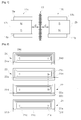
- FIG. 1 is a schematic diagram of a flat type speaker having a multi-layer PCB pattern voice coil film in accordance with the present invention.
- FIG. 1 A flat type speaker to which a voice film is applied according to the present invention is shown in FIG. 1 .
- the flat type speaker includes a pair of magnetic bodies 11a and 11 b spaced apart from each other at a specific interval and formed to face each other and a voice coil film 10 interposed between the pair of magnetic bodies 11a and 11b.
- the pair of magnetic bodies 11a and 11b that face each other have the same construction and may include permanent magnets 12a and 12b, upper yokes 13a and 13b placed on top surfaces of the permanent magnets 12a and 12b, and lower yokes 14a and 14b placed on bottom surfaces of the permanent magnets 12a and 12b.
- the permanent magnets 12a and 12b provided within the magnetic bodies 11a and 11b that face each other have opposite polarities such that attraction can act on between the permanent magnets 12a and 12b.
- the voice coil film 10 preferably maintains the same distance 'd' from the magnetic bodies 11a and 11b on both sides of the voice coil film 10 such that the voice coil film 10 is subject to the same magnetic force from the magnetic bodies 11a and 11 b.
- the speaker constructed as above is mounted within a base frame (not shown), and a vibration plate (not shown) for transferring vibration energy is formed over the voice coil film 10.
- the voice coil film 10 is formed of multiple layers stacked in 4-layer or more even-numbered layers 4, 6, 8, ....
- a 4-layer voice coil film is shown in FIG. 1 .
- a flat type speaker having a multi-layer PCB pattern voice coil film having an electrical connection structure can increase an existing number of PCB pattern turns up to 2 times to 3 times because only the resistance value of one layer has only to be managed while increasing the number of turns to a maximum extent and can implement a high-output speaker because induced electromotive force is greatly increased.
- a resistance value is 4 ⁇ and 8 ⁇
- the number of 20 to 25 turns can be wound on a structure stacked in four layers because it is difficult to manage a resistance value.
- the number of 50 to 60 turns can be wound on a 4-layer stack structure, and the number of turns can be further increased as the line diameter of a PCB pattern becomes thin.
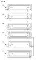
- FIG. 2 is a plan view showing a serial and parallel connection structure in the 4-layer stack structure of a multi-layer PCB pattern voice coil film in accordance with the present invention
- FIGS. 3 to 5 show the 6-layer PCB pattern voice coil film connection structures of flat type speakers having a multi-layer PCB pattern voice coil film in accordance with the present invention.
- a voice coil film stacked in four layers or six layers shows separated plane states, for convenience of description.
- FIGS. 2 to 5 are illustrated as being preferred embodiments, and multi-layer PCB pattern voice coil film structures having various shapes of serial and parallel connection structures are possible.
- a resistance value of each layer can be aware prior to PCB patterning although a voice coil is formed of what number. This principle is described below using Equation 1.
- L 2 ⁇ n + 1
- R layer 1 / 2 * R spec ⁇ n + 1
- L is the number of PCB layers (4-layer or more)
- R layer is a design resistance value of each PCB layer
- R spec is a target total resistance value of all the PCB layers
- n is a positive integer.
- R layer a design resistance value of each PCB layer
- the voice coils of the layers are connected in series by two layers, and one ends and the other ends of the serially connected voice coils and one ends and the other ends of another serially connected voice coils are shorted, thereby forming the entire multi-layer structure voice coil PCB pattern.
- through holes are formed in PCBs in order to enable such connections.
- Through holes 21 e and 31 e are formed in PCBs 21 a to 24a and 31 a to 36a at locations corresponding to the inside front ends 21 c and 31 c and the outside front ends 21 d and 31 d of voice coils 21 b and 31 b.
- the number of through holes formed on the outside on both sides of each of the PCBs in response to each of the outside front ends 21 d and 31 d is 2, and the number of through holes formed on the inside on the PCB in response to each of the inside front ends 21 c and 31 c is variable.
- the number of through holes corresponding to the outside front end is 2 and may have a fixed value irrespective of the number of stacked layers, but through holes corresponding to the inside front end is calculated as in Equation 2 below.
- L 2 ⁇ n + 1
- N 1 / 2 * L
- L is the number of PCB layers
- N is the number of through holes formed in the PCB at a location corresponding to the inside front end of a voice coil
- n is a positive integer.
- the through holes corresponding to the inside front ends 21 c and 31 c are for coupling voice coil films 21 to 24 or 31 to 36 in series by two, and the through holes corresponding to the outside front ends 21d and 31d are for shorting one ends and the other ends of the voice coil films 21 to 24 or 31 to 36 that are connected in series by two and coupling the voice coil films 21 to 24 or 31 to 36 in parallel.
- variable number of through holes corresponding to the inside front ends 21 c and 31 c is for preventing the serial connection of one pair of voice coils from being shorted with the other pair of voice coils when the inside front ends are connected in series. That is, a 4-layer stack voice coil film requires two through holes because 4 voice coil films are internally connected in series by two lines. In contrast, a 6-layer stack voice coil film requires three serial connection lines because 6 voice coil films are internally connected in series by two so that the 6 voice coil films are prevented from being shorted through three through holes. Likewise, an 8-layer or more stack voice coil film has the number of through holes corresponding to inside front ends according to Equation 2.
- a serial and parallel connection structure in a 4-layer stack structure is described based on the above description with reference to FIG. 2 .
- a total resistance value R spec of a 4-layer PCB pattern voice coil film is set to 8 ⁇
- the voice coil of each layer needs to be and can be designed to be 8 ⁇ based on the line diameter and length of PCB copper foil and Equations 1 and 2, and the number of through holes corresponding to an inside front end is set to 2 so that serial and parallel connections are possible.
- FIG. 2 has a structure in which the first-layer and the fourth-layer voice coil films 21 and 24 and the second-layer and the third-layer voice coil films 22 and 23 are connected in series, and the first-layer and the second-layer voice coil films 21 and 22 and the third-layer and the fourth-layer voice coil films 23 and 24 are connected in parallel.
- the number of turns and resistance values of the voice coil films 21 to 24 of the respective layers are identically designed, and the inside front end 21 c of the first-layer voice coil 21 and the inside front end 22c of the second-layer voice coil film 22 are connected through the through hole 21 e of the PCB 21 a such that the first-layer voice coil film 21 and the second-layer voice coil film 22 are connected in series.
- a resistance value becomes 16 ⁇ , that is, 8 ⁇ + 8 ⁇ .
- a resistance value becomes 16 ⁇ , that is, 8 ⁇ + 8 ⁇ .
- the first-layer voice coil film 21 and the fourth-layer voice coil film 24 are connected in series
- the second-layer voice coil film 22 and the third-layer voice coil film 23 are connected in series
- the first-layer and the second-layer voice coil films 21 and 22 are connected in parallel
- the third-layer and the fourth-layer voice coil films 23 and 24 are connected in parallel, becoming 16 ⁇ /2.
- the PCB pattern voice coil film having a total resistance value of 8 ⁇ is completed.
- first-layer and the second-layer voice coil films 21 and 22 may be connected in series
- third-layer and the fourth-layer voice coil films 23 and 24 may be connected in series
- first-layer and the fourth-layer voice coil films 21 and 24 and the second-layer and the third-layer voice coil films 22 and 23 may be connected in parallel.
- the serial and parallel connection patterns preferably are connected through the through holes corresponding to the inside front ends 21 c to 24c of the voice coils when the serial connection is performed and preferably are connected through the through holes corresponding to the outside front ends 21 d to 24d of the voice coils when the parallel connection is performed.
- the following conditions are necessary in order to manage an accurate resistance value, wind a larger number of turns, and increase induced electromotive force.
- An electric current needs to flow always in a constant direction in the PCB pattern voice coil of each layer, the PCB pattern voice coil of each layer has the same resistance value, a connection between the PCB pattern voice coils of layers does not include a jump or additional inefficient connection, and the input and output of a current signal need to be the front and rear of a multi-layer PCB pattern voice coil film.
- a serial connection between two layers is performed using a through hole at the central portion of the inside front end of a multi-layer PCB voice coil, and a parallel connection between the serially connected voice coils is performed by a connection between the outside front ends of PCB voice coils.
- FIG. 3 is a plan view showing a first serial and parallel connection structure in the 6-layer stack structure of a multi-layer PCB pattern voice coil film in accordance with the present invention.
- the number of through holes formed in each of the PCBs 31a to 36a is 2 on both sides at locations corresponding to the outside front ends of the voice coil, and the number of through holes corresponding to the inside front end of the voice coil needs to be 3 at an internal central part.
- the voice coil films 31 to 36 of the respective layers are designed to have the same number of turns and the same resistance value, and the inside front end 31c of a first-layer voice coil film 31 and the inside front end 36c of a sixth-layer voice coil film 36 are connected in series through the through hole 31e of the PCB 31 a.
- second-layer and fifth-layer voice coils 32 and 35 are connected in series.
- third-layer and fourth-layer voice coils 33 and 34 are connected in series by connecting the inside front ends 33c and 34c of the third-layer and fourth-layer voice coils 33 and 34.
- outside front ends 31d, 32d, and 33d of the first-layer to the third-layer voice coil films 31, 32, and 33 are shorted and connected in parallel
- outside front ends 34d, 35d, and 36d of the four-layer to the sixth-layer voice coil films 34, 35, and 36 are shorted and connected in parallel through the through holes of the PCBs 31 a to 36a.
- the resistance value R layer of each layer is designed to have 12 ⁇ in accordance with Equation 1.
- the serial connections each by two layers form three serially connected voice coils each having 24 ⁇ .
- a total resistance value becomes 8 ⁇ , that is, 24 ⁇ /3.
- Connection structures having other modified examples, such as FIGS. 4 and 5 , are possible using the same method as that of FIG. 3 .
- FIG. 4 shows a structure in which first-layer and fourth-layer voice coil films 41 and 44 are connected in series, second-layer and fifth-layer voice coil films 42 and 45 are connected in series, third-layer and sixth-layer voice coil films 43 and 46 are connected in series, one ends of the first-layer to third-layer voice coil films 41 to 43 are shorted and connected in parallel, and the other ends of the four-layer to the sixth-layer voice coil films 44 to 46 are shorted and connected in parallel.
- FIG. 5 shows a structure in which first-layer and second-layer voice coil films 41 and 42 are connected in series, third-layer and fourth-layer voice coil films 43 and 44 are connected in series, fifth-layer and sixth-layer voice coil films 45 and 46 are connected in series, one ends of the first-layer, the third-layer, and the fifth-layer voice coil films 41, 43, and 45 are shorted and connected in parallel, and the other ends of the second-layer, the four-layer and the sixth-layer voice coil films 42, 44, and 46 are shorted and connected in parallel.
- PCB pattern voice coil films can be produced freely and efficiently and applied easily.
- induced electromotive force can be maximized very simply and a resistance value can also be managed and implemented. Accordingly, a high-output speaker can be fabricated.
- a multi-layer PCB pattern may be formed in each of the layers in the process, all the layers may be stacked, all the layers may be perforated so that the through holes of all the layers are formed therein, and electrical connections between all the layers may be completed through the electrical plating of the through holes of all the layers.
- a multi-layer PCB pattern may be formed in each of the layers in the process, a layer may be perforated so that the through hole of the layer necessary in a stacking process is formed therein, and electrical connections between necessary layers may be completed through the electrical plating of the perforated through holes.
- a resistance value can be managed likewise, and stacked films can be connected in series and in parallel through through holes.
Landscapes
- Engineering & Computer Science (AREA)
- Physics & Mathematics (AREA)
- Acoustics & Sound (AREA)
- Signal Processing (AREA)
- Manufacturing & Machinery (AREA)
- Microelectronics & Electronic Packaging (AREA)
- Audible-Bandwidth Dynamoelectric Transducers Other Than Pickups (AREA)
- Diaphragms For Electromechanical Transducers (AREA)
Applications Claiming Priority (2)
| Application Number | Priority Date | Filing Date | Title |
|---|---|---|---|
| KR1020110043807A KR101147904B1 (ko) | 2011-05-11 | 2011-05-11 | 멀티 레이어 pcb 패턴 보이스 코일 필름을 갖는 평판형 스피커 |
| PCT/KR2012/002872 WO2012153921A2 (ko) | 2011-05-11 | 2012-04-16 | 멀티 레이어 pcb 패턴 보이스 코일 필름을 갖는 평판형 스피커 |
Publications (2)
| Publication Number | Publication Date |
|---|---|
| EP2709382A2 true EP2709382A2 (de) | 2014-03-19 |
| EP2709382A4 EP2709382A4 (de) | 2014-10-22 |
Family
ID=46272404
Family Applications (1)
| Application Number | Title | Priority Date | Filing Date |
|---|---|---|---|
| EP12781858.1A Withdrawn EP2709382A4 (de) | 2011-05-11 | 2012-04-16 | Flacher lautsprecher mit einem schwingspulenfilm mit einer mehrschichtigen leiterplatte |
Country Status (6)
| Country | Link |
|---|---|
| US (1) | US8953834B2 (de) |
| EP (1) | EP2709382A4 (de) |
| JP (1) | JP6005730B2 (de) |
| KR (1) | KR101147904B1 (de) |
| CN (1) | CN103563398A (de) |
| WO (1) | WO2012153921A2 (de) |
Cited By (1)
| Publication number | Priority date | Publication date | Assignee | Title |
|---|---|---|---|---|
| EP3751867A4 (de) * | 2018-02-06 | 2021-10-27 | Dong-Man Kim | Flachlautsprecher mit mehrschicht- und doppelspur-schwingspule |
Families Citing this family (29)
| Publication number | Priority date | Publication date | Assignee | Title |
|---|---|---|---|---|
| KR101425912B1 (ko) * | 2012-11-23 | 2014-08-05 | 주식회사 엑셀웨이 | 평판 스피커의 음압을 개선한 멀티레이어 pcb 보이스 코일판 |
| CN104618838A (zh) * | 2015-02-09 | 2015-05-13 | 张玮 | 一种动磁、平面涡旋多层联结式超薄受话器(扬声器) |
| DE102015102643A1 (de) * | 2015-02-24 | 2016-08-25 | Backes & Müller High End Audio Produktionsgesellschaft mbH | Sensor zum Erfassen einer Bewegung einer Lautsprechermembran |
| KR101717970B1 (ko) | 2015-04-28 | 2017-03-21 | 민동훈 | 다층 구조의 보이스 코일판 및 이를 포함하는 평판형 스피커 |
| KR101668617B1 (ko) * | 2015-06-22 | 2016-10-25 | 범진시엔엘 주식회사 | 스피커용 보이스판 제조 방법 |
| KR101544042B1 (ko) | 2015-06-22 | 2015-08-12 | 범진시엔엘 주식회사 | 스피커용 보이스판 |
| CN204887423U (zh) * | 2015-07-09 | 2015-12-16 | 张扬 | 微型发声器 |
| CN204887443U (zh) * | 2015-07-09 | 2015-12-16 | 张扬 | 微型发声器 |
| EP3541092B1 (de) * | 2015-09-30 | 2021-08-11 | Apple Inc. | Ohrhörergehäuse mit ladesystem |
| KR20170076170A (ko) * | 2015-12-24 | 2017-07-04 | 엘지이노텍 주식회사 | 다중 모드를 지원하는 무선 전력 송신기 |
| JP3221534U (ja) * | 2016-05-31 | 2019-06-06 | ▲トウ▼克忠 | 改良された構造を有する平面振動膜単体 |
| WO2017217308A1 (ja) * | 2016-06-17 | 2017-12-21 | 株式会社村田製作所 | 電子部品、振動板、電子機器および電子部品の製造方法 |
| KR101798921B1 (ko) | 2016-08-08 | 2017-11-17 | 민동훈 | 다층 구조의 보이스 코일판 및 이를 포함하는 평판형 스피커 |
| WO2018060247A1 (en) | 2016-09-27 | 2018-04-05 | At&S Austria Technologie & Systemtechnik Aktiengesellschaft | Flame retardant structure for component carrier |
| CN106341761A (zh) * | 2016-12-05 | 2017-01-18 | 陈新得 | 一种多磁路结构的扬声器 |
| KR102114435B1 (ko) * | 2018-03-12 | 2020-05-22 | 김동만 | 하이브리드 가동 코일판 및 이를 이용한 평판형 스피커 |
| CN112292871B (zh) * | 2018-08-06 | 2021-12-28 | 华为技术有限公司 | 包括改进的印刷线路板的电子设备 |
| KR102046430B1 (ko) * | 2018-08-30 | 2019-11-19 | 임성진 | 슬림 스피커용 멀티 패턴 코일을 갖는 보이스 코일판 |
| US11337007B2 (en) | 2018-08-30 | 2022-05-17 | Imusik Co., Ltd. | Voice coil plate having multi-patterned coil, and flat panel speaker comprising voice coil plate having multi-layered structure |
| KR102098076B1 (ko) * | 2018-09-13 | 2020-04-07 | 임성진 | 멀티 패턴 보이스 코일 및 다층 구조의 보이스 코일판을 포함하는 평판형 스피커 |
| US10743097B1 (en) * | 2019-02-25 | 2020-08-11 | Resonado Inc. | Bidirectional speaker using bar magnets |
| TWI734101B (zh) * | 2019-04-24 | 2021-07-21 | 周宏達 | 揚聲器結構 |
| KR102211558B1 (ko) * | 2019-09-16 | 2021-02-03 | 김동만 | 평판 스피커용 가동 코일 |
| US11044562B1 (en) | 2020-01-21 | 2021-06-22 | Resonado, Inc. | Multi-diaphragm speaker driven by multiple voice coil plates and a shared permanent magnet pair |
| EP3886289A1 (de) * | 2020-03-23 | 2021-09-29 | Sonova AG | Hörvorrichtung |
| US20230179074A1 (en) * | 2021-12-03 | 2023-06-08 | Sound Solutions International (Zhenjiang) Co., Ltd. | Method of manufacturing a voice coil with varying height profile and electrodynamic actuator, electrodynamic transducer and speaker with such a coil |
| KR20230164525A (ko) | 2022-05-25 | 2023-12-04 | 주식회사 엑추워드 | 평판 스피커용 복수의 라인 패턴을 갖는 보이스 코일판 |
| US20240064468A1 (en) * | 2022-08-16 | 2024-02-22 | Sound Solutions International (Zhenjiang) Co., Ltd. | Improved voice coil for an electrodynamic actuator with stacked conductive layers |
| IT202400002497A1 (it) * | 2024-02-07 | 2025-08-07 | Eldor Corp Spa | Trasduttore acustico |
Family Cites Families (15)
| Publication number | Priority date | Publication date | Assignee | Title |
|---|---|---|---|---|
| US3873784A (en) * | 1973-03-29 | 1975-03-25 | Audio Arts Inc | Acoustic transducer |
| JPS5863299A (ja) * | 1981-10-12 | 1983-04-15 | Shoji Taki | 平面振動板全面に対して均一に近い駆動力を与えるスピ−カ− |
| JPS5912693A (ja) * | 1982-07-13 | 1984-01-23 | Matsushita Electric Ind Co Ltd | 低音用スピ−カ |
| JPH10285690A (ja) * | 1997-04-01 | 1998-10-23 | Sony Corp | 音響変換器 |
| JPH1155788A (ja) * | 1997-08-04 | 1999-02-26 | Sony Corp | スピーカ装置 |
| JP2000201395A (ja) * | 1999-01-08 | 2000-07-18 | Sonic Window Kk | 平面型音響変換装置 |
| US7174024B1 (en) * | 1999-06-11 | 2007-02-06 | Fps, Inc. | Flat acoustic conversion device |
| EP2234410A3 (de) * | 2002-02-28 | 2010-10-06 | The Furukawa Electric Co., Ltd. | Planarer Lautsprecher |
| KR20040085569A (ko) * | 2003-03-26 | 2004-10-08 | 류강수 | 초 박형 스피커 |
| KR100547357B1 (ko) * | 2004-03-30 | 2006-01-26 | 삼성전기주식회사 | 휴대단말기용 스피커 및 그 제조방법 |
| KR100555416B1 (ko) * | 2004-08-23 | 2006-02-24 | 주식회사 이엠텍 | 편평형 보이스코일을 이용한 초슬림 사각형 마이크로 스피커 |
| JP2008177943A (ja) * | 2007-01-19 | 2008-07-31 | Mitsubishi Electric Engineering Co Ltd | 電磁変換器 |
| JP2008205216A (ja) * | 2007-02-20 | 2008-09-04 | Seiko Epson Corp | 積層コイルユニット並びにそれを有する電子機器及び充電器 |
| KR20090104325A (ko) * | 2008-03-31 | 2009-10-06 | 김상록 | 패턴 형태로 부착된 코일을 갖는 보이스 필름, 그 제조방법및 그것을 구비하는 평판형 스피커 |
| KR101042032B1 (ko) * | 2009-03-11 | 2011-06-16 | 주식회사 비에스이 | 마이크로 스피커 |
-
2011
- 2011-05-11 KR KR1020110043807A patent/KR101147904B1/ko not_active Expired - Fee Related
-
2012
- 2012-04-16 JP JP2014510240A patent/JP6005730B2/ja active Active
- 2012-04-16 WO PCT/KR2012/002872 patent/WO2012153921A2/ko not_active Ceased
- 2012-04-16 CN CN201280022716.0A patent/CN103563398A/zh active Pending
- 2012-04-16 EP EP12781858.1A patent/EP2709382A4/de not_active Withdrawn
- 2012-04-16 US US14/116,385 patent/US8953834B2/en active Active
Cited By (1)
| Publication number | Priority date | Publication date | Assignee | Title |
|---|---|---|---|---|
| EP3751867A4 (de) * | 2018-02-06 | 2021-10-27 | Dong-Man Kim | Flachlautsprecher mit mehrschicht- und doppelspur-schwingspule |
Also Published As
| Publication number | Publication date |
|---|---|
| CN103563398A (zh) | 2014-02-05 |
| KR101147904B1 (ko) | 2012-05-24 |
| JP2014517594A (ja) | 2014-07-17 |
| US8953834B2 (en) | 2015-02-10 |
| JP6005730B2 (ja) | 2016-10-12 |
| WO2012153921A3 (ko) | 2013-01-03 |
| WO2012153921A2 (ko) | 2012-11-15 |
| US20140105445A1 (en) | 2014-04-17 |
| EP2709382A4 (de) | 2014-10-22 |
Similar Documents
| Publication | Publication Date | Title |
|---|---|---|
| EP2709382A2 (de) | Flacher lautsprecher mit einem schwingspulenfilm mit einer mehrschichtigen leiterplatte | |
| KR102114435B1 (ko) | 하이브리드 가동 코일판 및 이를 이용한 평판형 스피커 | |
| CN111869235B (zh) | 具有多层及双轨道的可动线圈的平板型扬声器 | |
| US8879756B2 (en) | Voice film of multi-layered structure for flat type speaker | |
| US9210512B2 (en) | Flat-type speaker having plurality of magnetic circuits which are horizontally connected | |
| JP2011530172A5 (de) | ||
| US20210337313A1 (en) | Voice coil plate having multi-patterned coil, and flat panel speaker comprising voice coil plate having multi-layered structure | |
| JP2020061532A (ja) | コイル基板、モータ用コイル基板、モータとコイル基板の製造方法 | |
| CN111740631A (zh) | 谐振变换器及其变压器的制造方法 | |
| KR102098076B1 (ko) | 멀티 패턴 보이스 코일 및 다층 구조의 보이스 코일판을 포함하는 평판형 스피커 | |
| CN114667741B (zh) | 平板扬声器用可动线圈 | |
| KR20240021043A (ko) | 하이브리드 코일판과 이를 이용한 평판형 스피커 및 진동 드라이버 | |
| US20180295434A1 (en) | Printed circuit board used as voice coil, method for manufacturing the same and loudspeaker with the same | |
| KR20110059997A (ko) | 미세 코일 및 그 제조방법 | |
| KR20230164525A (ko) | 평판 스피커용 복수의 라인 패턴을 갖는 보이스 코일판 | |
| CN112019991A (zh) | 音圈、音圈的制作方法及扬声器 | |
| KR102046430B1 (ko) | 슬림 스피커용 멀티 패턴 코일을 갖는 보이스 코일판 | |
| JPS6113680B2 (de) |
Legal Events
| Date | Code | Title | Description |
|---|---|---|---|
| PUAI | Public reference made under article 153(3) epc to a published international application that has entered the european phase |
Free format text: ORIGINAL CODE: 0009012 |
|
| 17P | Request for examination filed |
Effective date: 20131129 |
|
| AK | Designated contracting states |
Kind code of ref document: A2 Designated state(s): AL AT BE BG CH CY CZ DE DK EE ES FI FR GB GR HR HU IE IS IT LI LT LU LV MC MK MT NL NO PL PT RO RS SE SI SK SM TR |
|
| DAX | Request for extension of the european patent (deleted) | ||
| A4 | Supplementary search report drawn up and despatched |
Effective date: 20140918 |
|
| RIC1 | Information provided on ipc code assigned before grant |
Ipc: H04R 7/04 20060101ALN20140912BHEP Ipc: H04R 9/04 20060101AFI20140912BHEP Ipc: H04R 7/10 20060101ALN20140912BHEP |
|
| 17Q | First examination report despatched |
Effective date: 20151221 |
|
| STAA | Information on the status of an ep patent application or granted ep patent |
Free format text: STATUS: THE APPLICATION IS DEEMED TO BE WITHDRAWN |
|
| 18D | Application deemed to be withdrawn |
Effective date: 20171104 |