EP2711220A2 - Anordnungsstruktur für Wetterstreifen - Google Patents
Anordnungsstruktur für Wetterstreifen Download PDFInfo
- Publication number
- EP2711220A2 EP2711220A2 EP13182159.7A EP13182159A EP2711220A2 EP 2711220 A2 EP2711220 A2 EP 2711220A2 EP 13182159 A EP13182159 A EP 13182159A EP 2711220 A2 EP2711220 A2 EP 2711220A2
- Authority
- EP
- European Patent Office
- Prior art keywords
- cabin side
- base member
- installation base
- wall
- cabin
- Prior art date
- Legal status (The legal status is an assumption and is not a legal conclusion. Google has not performed a legal analysis and makes no representation as to the accuracy of the status listed.)
- Granted
Links
Images


Classifications
-
- B—PERFORMING OPERATIONS; TRANSPORTING
- B60—VEHICLES IN GENERAL
- B60J—WINDOWS, WINDSCREENS, NON-FIXED ROOFS, DOORS, OR SIMILAR DEVICES FOR VEHICLES; REMOVABLE EXTERNAL PROTECTIVE COVERINGS SPECIALLY ADAPTED FOR VEHICLES
- B60J10/00—Sealing arrangements
- B60J10/30—Sealing arrangements characterised by the fastening means
-
- B—PERFORMING OPERATIONS; TRANSPORTING
- B60—VEHICLES IN GENERAL
- B60J—WINDOWS, WINDSCREENS, NON-FIXED ROOFS, DOORS, OR SIMILAR DEVICES FOR VEHICLES; REMOVABLE EXTERNAL PROTECTIVE COVERINGS SPECIALLY ADAPTED FOR VEHICLES
- B60J10/00—Sealing arrangements
- B60J10/20—Sealing arrangements characterised by the shape
- B60J10/24—Sealing arrangements characterised by the shape having tubular parts
-
- B—PERFORMING OPERATIONS; TRANSPORTING
- B60—VEHICLES IN GENERAL
- B60J—WINDOWS, WINDSCREENS, NON-FIXED ROOFS, DOORS, OR SIMILAR DEVICES FOR VEHICLES; REMOVABLE EXTERNAL PROTECTIVE COVERINGS SPECIALLY ADAPTED FOR VEHICLES
- B60J10/00—Sealing arrangements
- B60J10/20—Sealing arrangements characterised by the shape
- B60J10/25—Sealing arrangements characterised by the shape characterised by water drainage means
-
- B—PERFORMING OPERATIONS; TRANSPORTING
- B60—VEHICLES IN GENERAL
- B60J—WINDOWS, WINDSCREENS, NON-FIXED ROOFS, DOORS, OR SIMILAR DEVICES FOR VEHICLES; REMOVABLE EXTERNAL PROTECTIVE COVERINGS SPECIALLY ADAPTED FOR VEHICLES
- B60J10/00—Sealing arrangements
- B60J10/70—Sealing arrangements specially adapted for windows or windscreens
- B60J10/74—Sealing arrangements specially adapted for windows or windscreens for sliding window panes, e.g. sash guides
- B60J10/77—Sealing arrangements specially adapted for windows or windscreens for sliding window panes, e.g. sash guides for sashless windows, i.e. for frameless windows forming a seal directly with the vehicle body
-
- B—PERFORMING OPERATIONS; TRANSPORTING
- B60—VEHICLES IN GENERAL
- B60J—WINDOWS, WINDSCREENS, NON-FIXED ROOFS, DOORS, OR SIMILAR DEVICES FOR VEHICLES; REMOVABLE EXTERNAL PROTECTIVE COVERINGS SPECIALLY ADAPTED FOR VEHICLES
- B60J10/00—Sealing arrangements
- B60J10/90—Sealing arrangements specially adapted for non-fixed roofs, e.g. foldable roofs or removable hard-tops
Definitions
- the present invention relates to assembly structure of weather strips installed along door opening edges of retractable roof vehicles including convertible vehicles or hard top vehicles, that make elastic contact with door glasses for sealing outside and inside of vehicles.
- Fig. 5 is an external view of one type of retractable roof vehicles of which roofs that open and close are folded to open.
- the roof comprises a soft top 1 which is folded and put away in a trunk 2 on a lower rear side of a vehicle.
- Another roof of the retractable roof vehicle comprises a roof panel and a back window panel at the back of the roof panel instead of the soft top 1, which are folded and put away in the trunk 2 while the roof panel as folded is piled on the back window panel.
- Such vehicles are generally called retractable hard top, coupe cabriolet or coupe convertible.
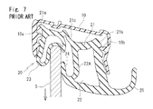
- a front pillar 3 and the soft top 1 as an opening edge of a door 2 have a weather strip 20 fit in a retainer 10 installed on side edges thereof.
- the weather strip 20 makes elastic contact with a door glass (side glass) 5 that lifts or lowers when the door 2 is closed to seal outside and inside of the vehicle.
- the weather strip 20 comprises: an installation base member 21 fit between an outer-cabin side holding part 10a and an inner- cabin side holding part 10b formed on the retainer 10; a hollow part 22 disposed between an inner-cabin side end 21b and a center of the installation base member 21; a hollow outer seal 23 integrally molded with an outer-cabin side of the installation base member 21, which makes elastic contact with an upper edge and an outer-cabin side surface of the door glass 5 that lifts or lowers when the door 2 is closed; and a lip-like inner seal 24 integrally molded with an outer-cabin side of the hollow part 22, which makes elastic contact with an inner-cabin side surface of the door glass 5 when the door 2 is closed.
- the hollow part 22 has a lip 25 on an inner-cabin side thereof which abuts interior material (not shown) including garnish.
- the hollow part 22 is a watercourse for draining water guided therein outside a vehicle on a front side of the vehicle.
- the Japanese examined Utility Model Publication No. H03-15401 discloses a structure that the outer seal and the inner seal of the weather strip installed on the retainer makes elastic contact with the outer-cabin side surface and the inner-cabin side surface of the door glass that lifts or lowers.
- the inner seal 24 which makes elastic contact with the inner-cabin side of the door glass 5 is pulled toward the installation base member 21 side.
- the inner seal 24 is dragged by the door glass 5, thereby generating tensile force lowering a central pillar 22A which connects with the inner seal 24. The tensile force is transmitted in a direction of lowering (downward in Fig.
- an outer-cabin side end 21a or the inner-cabin side end 21b of the installation base member 21 may come off respectively from the outer-cabin side holding part 10a or the inner-cabin side holding part 10b formed on the retainer 10.
- Examples of measures to the problem include altering shapes of the outer-cabin side holding part 10a and the inner- cabin side holding part 10b and providing additional holding parts for increasing holding force of the retainer 10 relative to the weather strip 20. But, as fitting force increases, it becomes harder to smoothly insert the weather strip 20 into the retainer 10.
- Another example is moving a connecting position of the central pillar 22A relative to the installation base member 21 to a position on an inner-cabin side end 21b side of the installation base member 21 for hampering force lowering the intermediate part 21c.
- the structure may cause another problem that size of the hollow part 22 reduces and the hollow part 22 does not sufficiently maintain function thereof as the watercourse for draining water.
- the Japanese examined Utility Model Publication No. H03-15401 discloses techniques of increasing fitting force and improving insertion property of the weather strip into the installation base member, the Japanese examined Utility Model Publication No. H03-15401 does not disclose the hollow part which functions as the watercourse for draining water as shown in Fig. 6 . Accordingly, the Japanese examined Utility Model Publication No. H03-15401 imposes less limitation on the shape of the weather strip.
- an object of the present invention is to provide the assembly structure of weather strips capable of securing stable holding force without difficulty in insertion while maintaining the watercourse for draining water.
- an assembly structure of a weather strip (40) comprising: an installation base member (41) fit in a frame body (30) installed on a door (2) opening edge of a retractable roof vehicle or a hard top vehicle, the frame body (30) including a part having a substantially U-shape in cross section; a hollow part (42) encircled by an inner-cabin side pillar part (42B) and a center pillar part (42A) vertically provided from an inner-cabin side end (41b) and a center part of said installation base member (41) respectively and a connecting part (42C) connecting ends of both pillar parts (42B, 42A); an outer seal (43) integrally molded with an outer-cabin side of said installation base member (41), said outer seal (43) making elastic contact with an outer-cabin side surface of a door glass (5) lifting or lowering when the door (2) is closed; and an inner seal (44) integrally molded with an outer-cabin side of said installation base member (41), said outer seal (43) making elastic contact with an outer-cab
- said inner seal (44) comprises a first wall (44A) and a second wall (44B) respectively extending from an end of said center pillar part (42A) and a part on a base root side of said center pillar part (42A) toward an outer-cabin side, said first wall (44A) and said second wall (44B) being connected with each other on one ends thereof in a curved state.
- said outer seal (43) is hollow, base roots of the said outer seal (43) being connected with the outer-cabin side end (41a) of said installation base member (41) and a part (41e) on an outer-cabin side of a connecting position of said center pillar part (42A) with said installation base member (41) respectively, and said outer seal (43) also making elastic contact with an upper edge of said door glass (5).
- a range between the inner-cabin side end (41b) of said installation base member (41) and the part (41e) on an outer-cabin side of the connecting position of said center pillar part (42A) with said installation base member (41) is swelled and curved in an opposite direction to said frame body (30) side.
- said second wall (44B) has a substantially V-shape in cross section, a center part of said second wall (44B) being bent to approach said first wall (44A) side.
- thickness (90) of a center part of said first wall (44A) is thicker than at least one other part of said first wall (44A).
- the outer-cabin side holding part and the inner-cabin side holding part are formed on the positions spaced out from the base surface of the frame body.
- the inner-cabin side holding part side is on the position further spaced out from the base surface than the outer-cabin side holding part side, that is the two holding parts are formed on uneven positions.
- the total of the distance between the anchoring part protrudingly provided on the inner-cabin side of the inner-cabin side pillar part and the base root of the inner-cabin side pillar part and the distance between the base root and the outer-cabin side end of the installation base member is longer than the straight-linear distance between the outer-cabin side holding part and the inner-cabin side holding part, and the outer-cabin side end and the anchoring part on the inner-cabin side of the installation base member are anchored with the outer-cabin side holding part and the inner-cabin side holding part respectively. Accordingly, even in case force acts in a direction that the installation base member comes off from the frame body as the inner seal makes elastic contact with the inner-cabin side of the door glass, the installation base member does not come off easily, thereby maintaining sufficient holding force.
- the structure is simple, which necessitates only anchoring the outer-cabin side end and the anchoring part on the inner-cabin side of the installation base member with two parts, the outer-cabin side holding part and the inner-cabin side holding part, respectively. Accordingly, insertion of the weather strip for assembly on the frame body is smooth and simple.
- the inner seal comprises the first wall and the second wall respectively extending from the end of the center pillar part and the part on the base root side of the center pillar part toward the outer-cabin side, the first wall and the second wall being connected with each other on one ends thereof.
- Such a structure generates a hollow between the first wall and the second wall. Accordingly, in the same manner as one of the functions of the hollow part, the inner seal can function as a watercourse for draining water guided therein outside the vehicle on a front side of the vehicle.
- the inner seal makes elastic contact with the door glass on a part thereof on which the first wall and the second wall are connected with each other in the curved state, not a lip-like part. Such a structure prevents reversal or turn.
- the outer seal is hollow, which is more excellent in sealing property relative to the door glass than lip-like outer seals. But the hollow outer seal can easily generate force which acts on the installation base member from the base root thereof on the inner-cabin side when making elastic contact with the door glass. Accordingly, the present invention is more effective in the weather strips of this shape.
- the range between the inner-cabin side end of the installation base member and the part on the outer-cabin side of the connecting position of the center pillar part with the installation base member is swelled and curved in the opposite direction to the frame body side.
- Such a structure enables installation of bolts or clips between the installation base member and the frame body for installing the frame body.
- a shape swelled and curved can easily generate force which acts on the installation base member from the base root on the inner-cabin side of the outer seal when making elastic contact with the door glass and the outer seal can easily follow the lowering door glass when opening the door glass. Accordingly, the present invention is more effective in the weather strips of this shape.
- the second wall has the substantially V-shape in cross section, the center part of the second wall being bent to approach the first wall side. Accordingly, a side surface of the first wall touches the surface of the door glass, not the top end of the first wall, thereby decreasing resistance when lifting or lowering the door glass.
- the inner seal makes elastic contact with the door glass while lowering the door glass, force pulling the installation base member via the second wall in a direction away from the frame body is controlled. Also, an elastic contact position on the inner seal relative to the door glass is stabilized.
- the thickness of the center part of the first wall is thicker than at least one other part of the first wall. Accordingly, an abutting part on the first wall with the door glass is stabilized when making elastic contact with the door glass, and when lowering the door glass, reversal of the inner seal is further prevented.
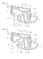
- Fig. 1 shows an assembly structure of a weather strip according to an embodiment of the present invention before a door glass 5 is guided therein while Fig. 2 shows a state after the door glass 5 is guided therein.
- Fig. 1 and Fig. 2 are I-I line enlarged cross sections of Fig. 5 but a soft top 1 is omitted in the Figs. When constituents or items correspond to those in prior arts, the same symbols are used.
- a weather strip 40 which makes elastic contact with a door glass (side glass) 5 is assembled on a retainer 30.
- a structure of the retractable roof vehicle is the same as that of the prior art.
- the retainer 30 is installed on a door 2 opening edge and functions as a frame body.
- the retainer 30 includes a part having a substantially U-shape in cross section comprising: a base surface 31; and an outer-cabin side surface 32 and an inner-cabin side surface 33, which extend from both ends of the base surface 31 respectively.
- the retainer 30 as a whole has the substantially U-shape in cross section.
- An outer-cabin side holding part 30a and an inner-cabin side holding part 30b which protrude toward an inner side are formed on an outer-cabin side and an inner-cabin side of the retainer 30 respectively.
- the outer-cabin side holding part 30a protrudes from a position which is on an inner-cabin side of the outer-cabin side surface 32 and spaced out from a base surface 31.
- the inner-cabin side holding part 30b protrudes from a position which is on an outer-cabin side of the inner-cabin side surface 33 and spaced out from the base surface 31.
- a distance between the outer-cabin side holding part 30a and the base surface 31 is at least a size which allows an outer-cabin side end 41a of an installation base member 41 of the weather strip 40 to come in.
- the inner-cabin side holding part 30b side is on a position further spaced out from the base surface 31 than the outer-cabin side holding part 30a side.
- a bent part 30c bent to protrude toward an outer-cabin side is formed on a connecting position between a position of the inner-cabin side holding part 30b and the base surface 31.
- the weather strip 40 mainly comprises: an installation base member 41; a hollow part; an outer seal 43; and an inner seal 44.
- the installation base member 41 is fit in the retainer 30 in a manner to face the base surface 31 of the retainer 30.
- An inner-cabin side end 41b of the installation base member 41 is made of sponge for reducing generation of noise caused by vibration of the door glass 5.
- a hollow part 42 is encircled by an inner-cabin side pillar part 42B and a center pillar part 42A vertically provided from the inner-cabin side end 41b and a center part of the installation base member 41 respectively and a connecting part 42C connecting ends of both pillar parts 42B, 42A.
- This encircled space for example, can function as a watercourse for draining water guided therein outside a vehicle on a front side of the vehicle.
- Thickness of the inner-cabin side pillar part 42B is thicker (about twice) than the center pillar part 42A.
- An anchoring part 41d is protrudingly provided on an inner-cabin side of the inner-cabin side pillar part 42B and is spaced out from a base root of the inner-cabin side pillar part 42B connected with the installation base member 41.
- the outer-cabin side end 41a and the anchoring part 41d of the installation base member 41 are anchored with the outer-cabin side holding part 30a and the inner-cabin side holding part 30b respectively for assembling the weather strip 40 on the retainer 30.
- a lip 45 which extends toward an inner-cabin side and abuts interior material including garnish (not shown) is provided on a connecting position between the inner-cabin side pillar part 42B and the connecting part 42C.
- the outer seal 43 is integrally molded with an outer-cabin side of the installation base member 41 and makes elastic contact with an outer-cabin side surface and an upper edge of the door glass 5 lifting or lowering when the door 2 is closed.
- the outer seal 43 is hollow and base roots of the outer seal 43 are connected with the outer-cabin side end 41a of the installation base member 41 and a part 41e on an outer-cabin side of a connecting position of the center pillar part 42A with the installation base member 41 respectively.
- the outer seal 43 is swelled and curved relative to a direction in which the door glass 5 lifts (direction opposite to the retainer 30 side), for making elastic contact with the upper edge of the door glass 5 without fail when the door 2 is closed. In other words, as shown in Fig. 2 , when the door glass 5 lifts while the door 2 is closed, the outer seal 43 makes elastic contact with the upper edge over the outer-cabin side surface of the door glass 5 in a manner to wrap the door glass 5.
- the inner seal 44 is integrally molded with an outer-cabin side of the center pillar part 42A and makes elastic contact with an inner-cabin side surface of the door glass 5 lifting or lowering when the door 2 is closed.
- the inner seal 44 is formed by connecting ends of the center pillar part 42A, that is: an end of a first wall 44A inclining and extending in a direction approaching the installation base member 41 on the outer-cabin side from a connecting position between the center pillar part 42A and the connecting part 42C; and an end of a second wall 44B inclining and extending in a direction away from the installation base member 41 on the outer-cabin side from a base root side of the center pillar part 42A, from the base root of the center pillar part 42A on the installation base member 41 in the present embodiment.
- a resultant connecting part makes elastic contact with the door glass 5.
- the connecting part of the first wall 44A and the second wall 44B, which makes elastic contact with the door glass 5 is in a curved state and a lip-like protrusion is not formed as in the prior art.
- the part encircled by the first wall 44A and the second wall 44B is hollow and, in the same manner as the hollow part 42, the part can function as a watercourse for draining water guided therein outside the vehicle on the front side of the vehicle.
- Thickness 90 of a center part of the first wall 44A is thicker than at least one other part of the first wall 44A. Accordingly, when a connected end of the first wall 44A and the second wall 44B as a top end of the inner seal 44 makes elastic contact with the door glass 5, an abutting part of the first wall 44A with the door glass 5 is stabilized. When the door glass 5 is lowered, the top end of the inner seal 44 is prevented from reversal to turn.
- the second wall 44B has the substantially V-shape in cross section, and the center part of the second wall 44B being bent to approach the first wall side 44A. Accordingly, when the top end of the inner seal 44 makes elastic contact with the door glass 5, a side surface of the first wall 44A touches the surface of the door glass 5, not the top end of the first wall 44A, thereby decreasing resistance when lifting or lowering the door glass 5. Especially, while lowering the door glass 5, force pulling an intermediate part 41c of the installation base member 41 via the second wall 44B in a direction away from the retainer 30 (downward direction in Fig. 2 ) is controlled.
- a range between the inner-cabin side end 41b of the installation base member 41 and at least a part 41e on an outer-cabin side of the connecting position of the center pillar part 42A with the installation base member 41 is swelled and curved in an arch-like shape toward an opposite side to the retainer 30 side.
- the intermediate part 41c is in the range thus swelled and curved.
- Bolts or clips (not shown) for fixing the retainer 30 are provided between the retainer 30 and the installation base member 41 thus swelled and curved, in a longitudinal direction in which the retainer 30 and the weather strip 40 extend at regular intervals.
- the outer-cabin side holding part 30a and the inner-cabin side holding part 30b are formed on the retainer 30.
- the outer-cabin side holding part 30a and the inner-cabin side holding part 30b are formed on positions spaced out from the base surface 31 of the retainer 30, and the inner-cabin side holding part 30b side is on the position further spaced out from the base surface 31 than the outer-cabin side holding part 30a side, that is two holding parts 30a, 30b are formed on uneven positions.
- the inner seal 44 makes elastic contact with the inner-cabin side of the door glass 5
- the inner seal 44 is dragged by the lowering door glass 5 and force acts on the center pillar part 42A which connects with the inner seal 44 in a lowering direction, that is a direction that the installation base member 41 comes off from the retainer 30, the installation base member 41 does not easily come off and sufficient holding force is maintained.
- the center pillar part 42A is provided around a center of width in an automobile width direction of the installation base member 41, the installation base member 41 may easily come off. The embodiment prevents the situation, thereby widening latitude in design of the weather strip 40.
- the structure is simple, which necessitates only anchoring the outer-cabin side end 41a and the anchoring part 41d of the installation base member 41 with two parts, the outer-cabin side holding part 30a and the inner-cabin side holding part 30b, respectively. Accordingly, insertion of the weather strip 40 for assembly on the frame body is smooth and simple.
- outer seal 43 of the embodiment of the present invention is hollow and makes elastic contact with the upper edge and the outer-cabin side surface of the door glass 5
- the outer seal 43 may also be a lip-like outer seal which makes elastic contact with the outer-cabin side surface of the door glass 5 as shown in Fig. 3 .
- the inner-cabin side end 41b of the installation base member 41 of the embodiment of the present invention is made of sponge for reducing generation of noise caused by vibration of the door glass 5
- the installation base member 41 as a whole may be integrally molded by solid rubber.
- the outer seal 43 of the embodiment of the present invention is swelled and curved relative to the direction in which the door glass 5 lifts (direction opposite to the retainer 30 side)
- the outer seal 43 may also have a substantially V-shape in cross section (opposite to the second wall 44B having a substantially V-shape in cross section in a bent direction), of which center part is bent to approach a connecting part side of the base surface 31 and the outer-cabin side surface 32 of the retainer 30 (outer-cabin side corner side of the retainer 30) as shown in Fig. 4 .
- the outer seal 43 swelled and curved ( Fig.
- the retainer 30 may also be installed along a door opening edge of a hard top vehicle.
- the retainer 30 is used as an example of the frame body on which the weather strip 40 is assembled, but the present invention is not limited to the retainer 30 and a sash and so on may also be used.
- any frame body including a part having a U-shape in cross section for fitting the installation base member 41 of the weather strip 40 is usable.
Landscapes
- Engineering & Computer Science (AREA)
- Mechanical Engineering (AREA)
- Seal Device For Vehicle (AREA)
Applications Claiming Priority (1)
| Application Number | Priority Date | Filing Date | Title |
|---|---|---|---|
| JP2012205825A JP6027830B2 (ja) | 2012-09-19 | 2012-09-19 | ウェザーストリップの組付構造 |
Publications (3)
| Publication Number | Publication Date |
|---|---|
| EP2711220A2 true EP2711220A2 (de) | 2014-03-26 |
| EP2711220A3 EP2711220A3 (de) | 2017-11-29 |
| EP2711220B1 EP2711220B1 (de) | 2020-02-19 |
Family
ID=49080723
Family Applications (1)
| Application Number | Title | Priority Date | Filing Date |
|---|---|---|---|
| EP13182159.7A Active EP2711220B1 (de) | 2012-09-19 | 2013-08-29 | Anordnungsstruktur für Wetterstreifen |
Country Status (3)
| Country | Link |
|---|---|
| US (1) | US8869457B2 (de) |
| EP (1) | EP2711220B1 (de) |
| JP (1) | JP6027830B2 (de) |
Families Citing this family (10)
| Publication number | Priority date | Publication date | Assignee | Title |
|---|---|---|---|---|
| JP2015009634A (ja) * | 2013-06-27 | 2015-01-19 | トヨタ自動車株式会社 | 車両用プレスドア構造及びドアガラスラン |
| JP5718519B1 (ja) * | 2014-11-20 | 2015-05-13 | 西川ゴム工業株式会社 | ドアウェザーストリップ |
| JP6485386B2 (ja) * | 2016-02-26 | 2019-03-20 | 豊田合成株式会社 | 自動車用ウエザストリップ |
| JP6677542B2 (ja) * | 2016-03-18 | 2020-04-08 | マツダ株式会社 | 格納式ルーフ付き自動車のシール構造 |
| JP6749800B2 (ja) * | 2016-06-28 | 2020-09-02 | 西川ゴム工業株式会社 | ウェザーストリップ |
| JP6496279B2 (ja) * | 2016-06-28 | 2019-04-03 | 西川ゴム工業株式会社 | ウェザーストリップ |
| JP6374446B2 (ja) * | 2016-07-06 | 2018-08-15 | 豊田合成株式会社 | ルーフサイドウエザストリップの取付構造 |
| US9809097B1 (en) | 2016-07-18 | 2017-11-07 | GM Global Technology Operations LLC | Pillar seal retainers for motor vehicle seal structures |
| JP6652473B2 (ja) | 2016-09-28 | 2020-02-26 | 豊田合成株式会社 | 自動車用ルーフサイドウエザストリップ |
| JP6885349B2 (ja) * | 2018-01-30 | 2021-06-16 | 豊田合成株式会社 | 自動車用ガラスラン |
Citations (1)
| Publication number | Priority date | Publication date | Assignee | Title |
|---|---|---|---|---|
| JPH0315401U (de) | 1988-12-09 | 1991-02-15 |
Family Cites Families (15)
| Publication number | Priority date | Publication date | Assignee | Title |
|---|---|---|---|---|
| JPS6130556U (ja) | 1984-07-30 | 1986-02-24 | 豊田合成株式会社 | ウエザ−ストリツプ |
| AU596919B2 (en) * | 1988-02-15 | 1990-05-17 | Toyoda Gosei Co. Ltd. | Weather strip for door glass |
| JPH01161109U (de) * | 1988-04-30 | 1989-11-09 | ||
| JPH0347257U (de) * | 1989-09-18 | 1991-05-01 | ||
| US5010689A (en) * | 1990-03-19 | 1991-04-30 | The Standard Products Company | Glass run channel |
| JPH10264655A (ja) * | 1997-03-27 | 1998-10-06 | Toyoda Gosei Co Ltd | 自動車用ウエザストリップ |
| JP3931023B2 (ja) * | 2000-07-06 | 2007-06-13 | 豊田合成株式会社 | ドアガラスラン |
| JP3885470B2 (ja) * | 2000-08-23 | 2007-02-21 | 豊田合成株式会社 | 車両用ガラスランおよびその製造方法 |
| JP3713547B2 (ja) * | 2000-08-30 | 2005-11-09 | 豊田合成株式会社 | 自動車用ガラスラン |
| JP2004149012A (ja) * | 2002-10-31 | 2004-05-27 | Toyoda Gosei Co Ltd | ウエザストリップの取付構造 |
| JP4236177B2 (ja) * | 2004-02-04 | 2009-03-11 | 本田技研工業株式会社 | ランチャンネル構造 |
| US7172239B2 (en) * | 2004-03-19 | 2007-02-06 | Toyoda Gosei Co., Ltd. | Sealing structure for vehicle door |
| CN1676362A (zh) * | 2004-03-29 | 2005-10-05 | 丰田合成株式会社 | 玻璃滑槽及其制造方法 |
| JP5100029B2 (ja) * | 2006-04-28 | 2012-12-19 | 豊田合成株式会社 | ガラスラン |
| JP4882740B2 (ja) * | 2006-12-28 | 2012-02-22 | 豊田合成株式会社 | 自動車用ルーフサイドウエザストリップ |
-
2012
- 2012-09-19 JP JP2012205825A patent/JP6027830B2/ja active Active
-
2013
- 2013-08-29 EP EP13182159.7A patent/EP2711220B1/de active Active
- 2013-09-05 US US14/018,702 patent/US8869457B2/en active Active
Patent Citations (1)
| Publication number | Priority date | Publication date | Assignee | Title |
|---|---|---|---|---|
| JPH0315401U (de) | 1988-12-09 | 1991-02-15 |
Also Published As
| Publication number | Publication date |
|---|---|
| US8869457B2 (en) | 2014-10-28 |
| JP6027830B2 (ja) | 2016-11-16 |
| US20140075848A1 (en) | 2014-03-20 |
| EP2711220A3 (de) | 2017-11-29 |
| JP2014058277A (ja) | 2014-04-03 |
| EP2711220B1 (de) | 2020-02-19 |
Similar Documents
| Publication | Publication Date | Title |
|---|---|---|
| EP2711220B1 (de) | Anordnungsstruktur für Wetterstreifen | |
| JP6512966B2 (ja) | モールの取付構造 | |
| JP5656928B2 (ja) | ドアウエザストリップ | |
| JP6134304B2 (ja) | ウェザーストリップ | |
| JP5705530B2 (ja) | 格納式ルーフ車用ウェザーストリップのシール構造 | |
| JP6065798B2 (ja) | 自動車用ガラスランの取付構造 | |
| JP2010070054A (ja) | 車両のドア構造 | |
| CN108116202B (zh) | 汽车车门用玻璃导槽的安装构造 | |
| JP2017177894A (ja) | 自動車ドア用シール材 | |
| JP5243104B2 (ja) | 車両用ドアの窓枠に取り付けられるガーニッシュ及びこのガーニッシュを取り付けた車両用ドア | |
| JP2008284933A (ja) | ドアウェザーストリップ | |
| JP2007069831A (ja) | 自動車用ドアウェザーストリップ | |
| JP6051918B2 (ja) | 車両用ドアサッシュ構造 | |
| JP2010234998A (ja) | ドアウエザストリップの取付構造 | |
| JP2005075168A (ja) | ウェザーストリップ | |
| JP7339892B2 (ja) | 自動車用ドアのシール構造 | |
| JP5486453B2 (ja) | 車両用ドアサッシュ構造 | |
| JP4106600B2 (ja) | 自動車用ガラスラン | |
| JP3664982B2 (ja) | バックドアのモール取付け構造 | |
| JP2010167967A (ja) | 自動車用ウェザーストリップの取付構造 | |
| JP2009078683A (ja) | ドアガラスランの構造 | |
| JP5162769B2 (ja) | 自動車用ウェザーストリップの取付構造 | |
| JP4716187B2 (ja) | 自動車ドアのシール構造 | |
| JP5326430B2 (ja) | ウエザストリップ | |
| JP2014031137A (ja) | 車両側部構造 |
Legal Events
| Date | Code | Title | Description |
|---|---|---|---|
| PUAI | Public reference made under article 153(3) epc to a published international application that has entered the european phase |
Free format text: ORIGINAL CODE: 0009012 |
|
| AK | Designated contracting states |
Kind code of ref document: A2 Designated state(s): AL AT BE BG CH CY CZ DE DK EE ES FI FR GB GR HR HU IE IS IT LI LT LU LV MC MK MT NL NO PL PT RO RS SE SI SK SM TR |
|
| AX | Request for extension of the european patent |
Extension state: BA ME |
|
| 17P | Request for examination filed |
Effective date: 20150710 |
|
| RBV | Designated contracting states (corrected) |
Designated state(s): AL AT BE BG CH CY CZ DE DK EE ES FI FR GB GR HR HU IE IS IT LI LT LU LV MC MK MT NL NO PL PT RO RS SE SI SK SM TR |
|
| PUAL | Search report despatched |
Free format text: ORIGINAL CODE: 0009013 |
|
| AK | Designated contracting states |
Kind code of ref document: A3 Designated state(s): AL AT BE BG CH CY CZ DE DK EE ES FI FR GB GR HR HU IE IS IT LI LT LU LV MC MK MT NL NO PL PT RO RS SE SI SK SM TR |
|
| AX | Request for extension of the european patent |
Extension state: BA ME |
|
| RIC1 | Information provided on ipc code assigned before grant |
Ipc: B60J 10/10 00000000ALI20171020BHEP Ipc: B60J 10/00 20160101AFI20171020BHEP Ipc: B60J 10/04 00000000ALI20171020BHEP |
|
| REG | Reference to a national code |
Ref country code: DE Ref legal event code: R079 Ref document number: 602013066105 Country of ref document: DE Free format text: PREVIOUS MAIN CLASS: B60J0010000000 Ipc: B60J0010770000 |
|
| GRAP | Despatch of communication of intention to grant a patent |
Free format text: ORIGINAL CODE: EPIDOSNIGR1 |
|
| STAA | Information on the status of an ep patent application or granted ep patent |
Free format text: STATUS: GRANT OF PATENT IS INTENDED |
|
| INTG | Intention to grant announced |
Effective date: 20191129 |
|
| RIC1 | Information provided on ipc code assigned before grant |
Ipc: B60J 10/30 20160101ALI20191115BHEP Ipc: B60J 10/77 20160101AFI20191115BHEP Ipc: B60J 10/25 20160101ALI20191115BHEP Ipc: B60J 10/90 20160101ALI20191115BHEP Ipc: B60J 10/24 20160101ALI20191115BHEP |
|
| GRAS | Grant fee paid |
Free format text: ORIGINAL CODE: EPIDOSNIGR3 |
|
| GRAA | (expected) grant |
Free format text: ORIGINAL CODE: 0009210 |
|
| STAA | Information on the status of an ep patent application or granted ep patent |
Free format text: STATUS: THE PATENT HAS BEEN GRANTED |
|
| AK | Designated contracting states |
Kind code of ref document: B1 Designated state(s): AL AT BE BG CH CY CZ DE DK EE ES FI FR GB GR HR HU IE IS IT LI LT LU LV MC MK MT NL NO PL PT RO RS SE SI SK SM TR |
|
| REG | Reference to a national code |
Ref country code: GB Ref legal event code: FG4D |
|
| REG | Reference to a national code |
Ref country code: CH Ref legal event code: EP |
|
| REG | Reference to a national code |
Ref country code: DE Ref legal event code: R096 Ref document number: 602013066105 Country of ref document: DE |
|
| REG | Reference to a national code |
Ref country code: AT Ref legal event code: REF Ref document number: 1234552 Country of ref document: AT Kind code of ref document: T Effective date: 20200315 |
|
| REG | Reference to a national code |
Ref country code: IE Ref legal event code: FG4D |
|
| REG | Reference to a national code |
Ref country code: NL Ref legal event code: MP Effective date: 20200219 |
|
| PG25 | Lapsed in a contracting state [announced via postgrant information from national office to epo] |
Ref country code: NO Free format text: LAPSE BECAUSE OF FAILURE TO SUBMIT A TRANSLATION OF THE DESCRIPTION OR TO PAY THE FEE WITHIN THE PRESCRIBED TIME-LIMIT Effective date: 20200519 Ref country code: FI Free format text: LAPSE BECAUSE OF FAILURE TO SUBMIT A TRANSLATION OF THE DESCRIPTION OR TO PAY THE FEE WITHIN THE PRESCRIBED TIME-LIMIT Effective date: 20200219 Ref country code: RS Free format text: LAPSE BECAUSE OF FAILURE TO SUBMIT A TRANSLATION OF THE DESCRIPTION OR TO PAY THE FEE WITHIN THE PRESCRIBED TIME-LIMIT Effective date: 20200219 |
|
| REG | Reference to a national code |
Ref country code: LT Ref legal event code: MG4D |
|
| PG25 | Lapsed in a contracting state [announced via postgrant information from national office to epo] |
Ref country code: IS Free format text: LAPSE BECAUSE OF FAILURE TO SUBMIT A TRANSLATION OF THE DESCRIPTION OR TO PAY THE FEE WITHIN THE PRESCRIBED TIME-LIMIT Effective date: 20200619 Ref country code: GR Free format text: LAPSE BECAUSE OF FAILURE TO SUBMIT A TRANSLATION OF THE DESCRIPTION OR TO PAY THE FEE WITHIN THE PRESCRIBED TIME-LIMIT Effective date: 20200520 Ref country code: BG Free format text: LAPSE BECAUSE OF FAILURE TO SUBMIT A TRANSLATION OF THE DESCRIPTION OR TO PAY THE FEE WITHIN THE PRESCRIBED TIME-LIMIT Effective date: 20200519 Ref country code: SE Free format text: LAPSE BECAUSE OF FAILURE TO SUBMIT A TRANSLATION OF THE DESCRIPTION OR TO PAY THE FEE WITHIN THE PRESCRIBED TIME-LIMIT Effective date: 20200219 Ref country code: LV Free format text: LAPSE BECAUSE OF FAILURE TO SUBMIT A TRANSLATION OF THE DESCRIPTION OR TO PAY THE FEE WITHIN THE PRESCRIBED TIME-LIMIT Effective date: 20200219 Ref country code: HR Free format text: LAPSE BECAUSE OF FAILURE TO SUBMIT A TRANSLATION OF THE DESCRIPTION OR TO PAY THE FEE WITHIN THE PRESCRIBED TIME-LIMIT Effective date: 20200219 |
|
| PG25 | Lapsed in a contracting state [announced via postgrant information from national office to epo] |
Ref country code: NL Free format text: LAPSE BECAUSE OF FAILURE TO SUBMIT A TRANSLATION OF THE DESCRIPTION OR TO PAY THE FEE WITHIN THE PRESCRIBED TIME-LIMIT Effective date: 20200219 |
|
| PG25 | Lapsed in a contracting state [announced via postgrant information from national office to epo] |
Ref country code: DK Free format text: LAPSE BECAUSE OF FAILURE TO SUBMIT A TRANSLATION OF THE DESCRIPTION OR TO PAY THE FEE WITHIN THE PRESCRIBED TIME-LIMIT Effective date: 20200219 Ref country code: LT Free format text: LAPSE BECAUSE OF FAILURE TO SUBMIT A TRANSLATION OF THE DESCRIPTION OR TO PAY THE FEE WITHIN THE PRESCRIBED TIME-LIMIT Effective date: 20200219 Ref country code: ES Free format text: LAPSE BECAUSE OF FAILURE TO SUBMIT A TRANSLATION OF THE DESCRIPTION OR TO PAY THE FEE WITHIN THE PRESCRIBED TIME-LIMIT Effective date: 20200219 Ref country code: SK Free format text: LAPSE BECAUSE OF FAILURE TO SUBMIT A TRANSLATION OF THE DESCRIPTION OR TO PAY THE FEE WITHIN THE PRESCRIBED TIME-LIMIT Effective date: 20200219 Ref country code: RO Free format text: LAPSE BECAUSE OF FAILURE TO SUBMIT A TRANSLATION OF THE DESCRIPTION OR TO PAY THE FEE WITHIN THE PRESCRIBED TIME-LIMIT Effective date: 20200219 Ref country code: CZ Free format text: LAPSE BECAUSE OF FAILURE TO SUBMIT A TRANSLATION OF THE DESCRIPTION OR TO PAY THE FEE WITHIN THE PRESCRIBED TIME-LIMIT Effective date: 20200219 Ref country code: PT Free format text: LAPSE BECAUSE OF FAILURE TO SUBMIT A TRANSLATION OF THE DESCRIPTION OR TO PAY THE FEE WITHIN THE PRESCRIBED TIME-LIMIT Effective date: 20200712 Ref country code: EE Free format text: LAPSE BECAUSE OF FAILURE TO SUBMIT A TRANSLATION OF THE DESCRIPTION OR TO PAY THE FEE WITHIN THE PRESCRIBED TIME-LIMIT Effective date: 20200219 Ref country code: SM Free format text: LAPSE BECAUSE OF FAILURE TO SUBMIT A TRANSLATION OF THE DESCRIPTION OR TO PAY THE FEE WITHIN THE PRESCRIBED TIME-LIMIT Effective date: 20200219 |
|
| REG | Reference to a national code |
Ref country code: AT Ref legal event code: MK05 Ref document number: 1234552 Country of ref document: AT Kind code of ref document: T Effective date: 20200219 |
|
| REG | Reference to a national code |
Ref country code: DE Ref legal event code: R097 Ref document number: 602013066105 Country of ref document: DE |
|
| PLBE | No opposition filed within time limit |
Free format text: ORIGINAL CODE: 0009261 |
|
| STAA | Information on the status of an ep patent application or granted ep patent |
Free format text: STATUS: NO OPPOSITION FILED WITHIN TIME LIMIT |
|
| 26N | No opposition filed |
Effective date: 20201120 |
|
| PG25 | Lapsed in a contracting state [announced via postgrant information from national office to epo] |
Ref country code: IT Free format text: LAPSE BECAUSE OF FAILURE TO SUBMIT A TRANSLATION OF THE DESCRIPTION OR TO PAY THE FEE WITHIN THE PRESCRIBED TIME-LIMIT Effective date: 20200219 Ref country code: AT Free format text: LAPSE BECAUSE OF FAILURE TO SUBMIT A TRANSLATION OF THE DESCRIPTION OR TO PAY THE FEE WITHIN THE PRESCRIBED TIME-LIMIT Effective date: 20200219 |
|
| PG25 | Lapsed in a contracting state [announced via postgrant information from national office to epo] |
Ref country code: PL Free format text: LAPSE BECAUSE OF FAILURE TO SUBMIT A TRANSLATION OF THE DESCRIPTION OR TO PAY THE FEE WITHIN THE PRESCRIBED TIME-LIMIT Effective date: 20200219 Ref country code: SI Free format text: LAPSE BECAUSE OF FAILURE TO SUBMIT A TRANSLATION OF THE DESCRIPTION OR TO PAY THE FEE WITHIN THE PRESCRIBED TIME-LIMIT Effective date: 20200219 |
|
| PG25 | Lapsed in a contracting state [announced via postgrant information from national office to epo] |
Ref country code: MC Free format text: LAPSE BECAUSE OF FAILURE TO SUBMIT A TRANSLATION OF THE DESCRIPTION OR TO PAY THE FEE WITHIN THE PRESCRIBED TIME-LIMIT Effective date: 20200219 |
|
| REG | Reference to a national code |
Ref country code: CH Ref legal event code: PL |
|
| PG25 | Lapsed in a contracting state [announced via postgrant information from national office to epo] |
Ref country code: CH Free format text: LAPSE BECAUSE OF NON-PAYMENT OF DUE FEES Effective date: 20200831 Ref country code: LI Free format text: LAPSE BECAUSE OF NON-PAYMENT OF DUE FEES Effective date: 20200831 Ref country code: LU Free format text: LAPSE BECAUSE OF NON-PAYMENT OF DUE FEES Effective date: 20200829 |
|
| REG | Reference to a national code |
Ref country code: BE Ref legal event code: MM Effective date: 20200831 |
|
| PG25 | Lapsed in a contracting state [announced via postgrant information from national office to epo] |
Ref country code: FR Free format text: LAPSE BECAUSE OF NON-PAYMENT OF DUE FEES Effective date: 20200831 |
|
| PG25 | Lapsed in a contracting state [announced via postgrant information from national office to epo] |
Ref country code: IE Free format text: LAPSE BECAUSE OF NON-PAYMENT OF DUE FEES Effective date: 20200829 Ref country code: BE Free format text: LAPSE BECAUSE OF NON-PAYMENT OF DUE FEES Effective date: 20200831 |
|
| PG25 | Lapsed in a contracting state [announced via postgrant information from national office to epo] |
Ref country code: TR Free format text: LAPSE BECAUSE OF FAILURE TO SUBMIT A TRANSLATION OF THE DESCRIPTION OR TO PAY THE FEE WITHIN THE PRESCRIBED TIME-LIMIT Effective date: 20200219 Ref country code: MT Free format text: LAPSE BECAUSE OF FAILURE TO SUBMIT A TRANSLATION OF THE DESCRIPTION OR TO PAY THE FEE WITHIN THE PRESCRIBED TIME-LIMIT Effective date: 20200219 Ref country code: CY Free format text: LAPSE BECAUSE OF FAILURE TO SUBMIT A TRANSLATION OF THE DESCRIPTION OR TO PAY THE FEE WITHIN THE PRESCRIBED TIME-LIMIT Effective date: 20200219 |
|
| PG25 | Lapsed in a contracting state [announced via postgrant information from national office to epo] |
Ref country code: MK Free format text: LAPSE BECAUSE OF FAILURE TO SUBMIT A TRANSLATION OF THE DESCRIPTION OR TO PAY THE FEE WITHIN THE PRESCRIBED TIME-LIMIT Effective date: 20200219 Ref country code: AL Free format text: LAPSE BECAUSE OF FAILURE TO SUBMIT A TRANSLATION OF THE DESCRIPTION OR TO PAY THE FEE WITHIN THE PRESCRIBED TIME-LIMIT Effective date: 20200219 |
|
| PGFP | Annual fee paid to national office [announced via postgrant information from national office to epo] |
Ref country code: GB Payment date: 20220707 Year of fee payment: 10 |
|
| GBPC | Gb: european patent ceased through non-payment of renewal fee |
Effective date: 20230829 |
|
| PG25 | Lapsed in a contracting state [announced via postgrant information from national office to epo] |
Ref country code: GB Free format text: LAPSE BECAUSE OF NON-PAYMENT OF DUE FEES Effective date: 20230829 |
|
| PG25 | Lapsed in a contracting state [announced via postgrant information from national office to epo] |
Ref country code: GB Free format text: LAPSE BECAUSE OF NON-PAYMENT OF DUE FEES Effective date: 20230829 |
|
| PGFP | Annual fee paid to national office [announced via postgrant information from national office to epo] |
Ref country code: DE Payment date: 20250702 Year of fee payment: 13 |