EP2711296A2 - Agencement de refroidissement pour ensemble moteur et procédé de refroidissement d'un ensemble moteur - Google Patents
Agencement de refroidissement pour ensemble moteur et procédé de refroidissement d'un ensemble moteur Download PDFInfo
- Publication number
- EP2711296A2 EP2711296A2 EP13178415.9A EP13178415A EP2711296A2 EP 2711296 A2 EP2711296 A2 EP 2711296A2 EP 13178415 A EP13178415 A EP 13178415A EP 2711296 A2 EP2711296 A2 EP 2711296A2
- Authority
- EP
- European Patent Office
- Prior art keywords
- cooling
- motor
- flow
- motor controller
- arrangement
- Prior art date
- Legal status (The legal status is an assumption and is not a legal conclusion. Google has not performed a legal analysis and makes no representation as to the accuracy of the status listed.)
- Granted
Links
Images



Classifications
-
- F—MECHANICAL ENGINEERING; LIGHTING; HEATING; WEAPONS; BLASTING
- F04—POSITIVE - DISPLACEMENT MACHINES FOR LIQUIDS; PUMPS FOR LIQUIDS OR ELASTIC FLUIDS
- F04D—NON-POSITIVE-DISPLACEMENT PUMPS
- F04D29/00—Details, component parts, or accessories
- F04D29/58—Cooling; Heating; Diminishing heat transfer
- F04D29/5806—Cooling the drive system
-
- H—ELECTRICITY
- H02—GENERATION; CONVERSION OR DISTRIBUTION OF ELECTRIC POWER
- H02K—DYNAMO-ELECTRIC MACHINES
- H02K9/00—Arrangements for cooling or ventilating
- H02K9/02—Arrangements for cooling or ventilating by ambient air flowing through the machine
- H02K9/04—Arrangements for cooling or ventilating by ambient air flowing through the machine having means for generating a flow of cooling medium
- H02K9/06—Arrangements for cooling or ventilating by ambient air flowing through the machine having means for generating a flow of cooling medium with fans or impellers driven by the machine shaft
-
- F—MECHANICAL ENGINEERING; LIGHTING; HEATING; WEAPONS; BLASTING
- F04—POSITIVE - DISPLACEMENT MACHINES FOR LIQUIDS; PUMPS FOR LIQUIDS OR ELASTIC FLUIDS
- F04D—NON-POSITIVE-DISPLACEMENT PUMPS
- F04D25/00—Pumping installations or systems
- F04D25/02—Units comprising pumps and their driving means
- F04D25/06—Units comprising pumps and their driving means the pump being electrically driven
-
- F—MECHANICAL ENGINEERING; LIGHTING; HEATING; WEAPONS; BLASTING
- F04—POSITIVE - DISPLACEMENT MACHINES FOR LIQUIDS; PUMPS FOR LIQUIDS OR ELASTIC FLUIDS
- F04D—NON-POSITIVE-DISPLACEMENT PUMPS
- F04D29/00—Details, component parts, or accessories
- F04D29/58—Cooling; Heating; Diminishing heat transfer
- F04D29/5813—Cooling the control unit
-
- H—ELECTRICITY
- H02—GENERATION; CONVERSION OR DISTRIBUTION OF ELECTRIC POWER
- H02K—DYNAMO-ELECTRIC MACHINES
- H02K11/00—Structural association of dynamo-electric machines with electric components or with devices for shielding, monitoring or protection
- H02K11/30—Structural association with control circuits or drive circuits
- H02K11/33—Drive circuits, e.g. power electronics
-
- H—ELECTRICITY
- H02—GENERATION; CONVERSION OR DISTRIBUTION OF ELECTRIC POWER
- H02K—DYNAMO-ELECTRIC MACHINES
- H02K9/00—Arrangements for cooling or ventilating
- H02K9/14—Arrangements for cooling or ventilating wherein gaseous cooling medium circulates between the machine casing and a surrounding mantle
- H02K9/18—Arrangements for cooling or ventilating wherein gaseous cooling medium circulates between the machine casing and a surrounding mantle wherein the external part of the closed circuit comprises a heat exchanger structurally associated with the machine casing
-
- B—PERFORMING OPERATIONS; TRANSPORTING
- B64—AIRCRAFT; AVIATION; COSMONAUTICS
- B64D—EQUIPMENT FOR FITTING IN OR TO AIRCRAFT; FLIGHT SUITS; PARACHUTES; ARRANGEMENT OR MOUNTING OF POWER PLANTS OR PROPULSION TRANSMISSIONS IN AIRCRAFT
- B64D13/00—Arrangements or adaptations of air-treatment apparatus for aircraft crew or passengers, or freight space
- B64D13/06—Arrangements or adaptations of air-treatment apparatus for aircraft crew or passengers, or freight space the air being conditioned
- B64D2013/0603—Environmental Control Systems
- B64D2013/0644—Environmental Control Systems including electric motors or generators
-
- B—PERFORMING OPERATIONS; TRANSPORTING
- B64—AIRCRAFT; AVIATION; COSMONAUTICS
- B64D—EQUIPMENT FOR FITTING IN OR TO AIRCRAFT; FLIGHT SUITS; PARACHUTES; ARRANGEMENT OR MOUNTING OF POWER PLANTS OR PROPULSION TRANSMISSIONS IN AIRCRAFT
- B64D33/00—Arrangement in aircraft of power plant parts or auxiliaries not otherwise provided for
- B64D33/08—Arrangement in aircraft of power plant parts or auxiliaries not otherwise provided for of power plant cooling systems
-
- Y—GENERAL TAGGING OF NEW TECHNOLOGICAL DEVELOPMENTS; GENERAL TAGGING OF CROSS-SECTIONAL TECHNOLOGIES SPANNING OVER SEVERAL SECTIONS OF THE IPC; TECHNICAL SUBJECTS COVERED BY FORMER USPC CROSS-REFERENCE ART COLLECTIONS [XRACs] AND DIGESTS
- Y02—TECHNOLOGIES OR APPLICATIONS FOR MITIGATION OR ADAPTATION AGAINST CLIMATE CHANGE
- Y02T—CLIMATE CHANGE MITIGATION TECHNOLOGIES RELATED TO TRANSPORTATION
- Y02T50/00—Aeronautics or air transport
- Y02T50/50—On board measures aiming to increase energy efficiency
Definitions
- the present invention relates to a motor assembly, and more particularly to a cooling arrangement for the motor assembly, as well as a method of cooling the motor assembly.
- the ram air flow in an aircraft may serve various purposes, such as in cooling systems for the aircraft.
- the ram air flow may be utilized to remove heat from various aircraft lubrication and electrical systems and/or be used to condition aircraft cabin air.
- the movement of the aircraft creates a sufficient source of ram air flow which can be used for the purposes described above.
- a fan is typically utilized to supply air flow to the cooling systems. Such a fan is driven by an electric motor which, in turn, must be cooled by air flowing across it.
- the electric motor is controlled by a motor controller that is typically disposed at a location remote from the electric motor and the ram air fan, such as in a remote rack with other controllers and/or electrical components. Both the electric motor and the motor controller require cooling to maintain effective operation. Ineffective cooling of these components may lead to failure or inefficient operation. Additionally, the remote location of the motor controller and the electric motor require distinct and excessive cooling sources and flows.
- Cooling of the motor controller with the fan by locating the motor controller in close proximity to the fan also introduces undesirable effects, as fans, especially ram air fans, are located such that they draw air from the harsh ambient. Harsh in this regard describes the presence of moisture, water, corrosive substances, aircraft cleaning liquid, foreign objects, etc.
- the motor controllers typically require forced air cooling through the motor controller. Use of air from harsh ambient can thereby result in reduced reliability and result in shortened time between failures for such co-located motor controller.
- a cooling arrangement for a motor assembly includes motor operably connected to a load. Also included is a motor controller disposed adjacent to, and fluidly coupled to, the motor, the motor controller disposed within a housing enclosing a cooling fluid for immersion of a plurality of motor controller components. Further included is a duct arrangement configured to route a cooling flow to a location proximate the housing of the motor controller for cooling therealong.
- a method of cooling a motor assembly includes routing a main flow into a conduit. Also included is extracting a cooling flow from at least a portion of the main flow from the conduit to a duct arrangement in fluid communication with the conduit. Further included is routing the cooling flow through the duct arrangement to a location proximate a motor controller disposed adjacent a motor. Yet further included is cooling the motor controller during routing of the cooling flow along an outer surface of a housing of the motor controller. Also included is expelling the cooling flow to a motor located adjacent the motor controller for cooling of the motor.
- the cooling system 10 described herein may be used in conjunction with an assembly or system of a vehicle, such as an aircraft, however, it is contemplated that other vehicles may benefit from the embodiments described herein.
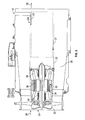
- the cooling system 10 includes a motor assembly 12 and a heat exchanger 14 disposed in close proximity thereto.
- the motor assembly 12 may be employed to drive a variety of contemplated loads and in the exemplary embodiment, the load is a ram air fan 22.
- the heat exchanger 14 is configured to ingest a fluid, such as a main flow 18.
- the main flow 18 may be sourced from ambient air through a conduit 11 and is drawn into the heat exchanger 14 through a heat exchanger inlet 17 via a pressure drop across the heat exchanger 14. Subsequently, the main flow is expelled via a heat exchanger outlet 19.
- a cooling arrangement 16 is generally illustrated and includes a duct arrangement 20 in fluid communication with the conduit 11 and configured to route at least a portion of the main flow 18 to the motor assembly 12. The routed portion of the main flow 18 is routed as a cooling flow 21 to the motor assembly 12.
- the motor assembly 12 includes the ram air fan 22 disposed proximate a fan inlet 24.
- a ram air flow 26 flows into the fan inlet 24 and through a fan passage 28 for cooling of various components and systems via a fan outlet 29.
- the ram air fan 22 is operably connected to a ram air fan motor 30 via at least one shaft 32.
- the ram air fan motor 30, located in a motor housing 33, is an electric motor having a rotor 34 rotatably located proximate the at least one shaft 32, and a stator 36 having a plurality of stator windings 38 disposed radially outboard of the rotor 34.
- the ram air fan motor 30 is controlled by a ram air fan motor controller 50 (shown in phantom) disposed relatively adjacent to the ram air fan motor 30.
- the ram air fan motor 30 also includes at least one bearing 40 disposed proximate the at least one shaft 32.
- the ram air fan 22 driven by the ram air fan motor 30 is configured to urge additional air flow through the fan inlet 24 when natural airflow into the fan inlet 24 is not sufficient to meet the requirements of the aircraft.
- cooling of these components is desirable.
- the cooling flow 18 may be routed to a plurality of locations of the motor assembly 12, in an exemplary embodiment the cooling flow 21 is routed to a location proximate an upstream end 42 of the ram air fan motor controller 50.
- upstream and downstream are used herein to refer to a predominant direction of flow of the cooling flow 21.
- the cooling flow 21 flows proximate the ram air fan motor controller 50 and subsequently the ram air fan motor 30 for cooling therealong.
- the ram air fan motor controller 50 comprises a housing 52 for enclosing a plurality of ram air fan motor controller components for controlling the ram air fan motor 30.
- the housing 52 may be of various cross sectional geometries, including the illustrated circular or tubular geometry, however, numerous other geometries are contemplated, such as rectangular, for example.
- a cooling fluid 62 is disposed within an interior region of the housing 52 for immersing the plurality of ram air fan motor controller components disposed therein.
- the cooling fluid 62 may be any fluid suitable for cooling of electrical components, such as a dielectric immersion cooling fluid.
- Fluorocarbon liquids are an example of such a fluid, an in an exemplary embodiment FC-72 is employed within the housing 52.
- Cooling of the plurality of ram air fan motor controller components comprises a two-phase immersion cooling, as the phase change from liquid to vapor provides efficient cooling.
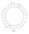
- the housing 52 also includes a plurality of condenser fins 64 extending radially outwardly from the housing 52.
- the housing 52 is surrounded by or comprises a condenser 70 that is configured to receive the cooling flow 21 and is employed to condense the above-described vapor as the cooling flow 21 passes over the plurality of condenser fins 64.
- the cooling flow 21 is routed to an upstream end 42 of the ram air fan motor controller 50 and in the illustrated embodiment the cooling flow 21 is routed to an upstream region of the condenser 70 through a cooling flow inlet 72.
- the cooling flow 21 is then routed in a downstream direction 74 within an annulus 76 formed by the housing 52 and a duct liner 56.
- the cooling flow 21 is routed through a cooling flow outlet 78 located proximate a downstream end 80 of the condenser 70 and the housing 52.
- the cooling flow 21 is routed to the ram air fan motor 30, which is located at a downstream, adjacent location relative to the ram air fan motor controller 50.
- the above-described structure provides an integrated and closely disposed motor assembly 12.
- a single source and path of the cooling flow 21 may be employed to efficiently cool both the ram air fan motor controller 50 and the ram air fan motor 30.
- the ram air fan motor controller 50 electronics are less prone to failure due to cooling efforts based on immersion cooling of the ram air fan motor controller 50 electronics that are sealed from the external harsh atmosphere. Rather, the condenser fins 64 are exposed to ambient air, thereby alleviating the need for forced air flow to the fan motor controller electronics. In this manner, this ram air fan motor controller 50 can be operated in a harsh environment.
- a method of cooling a motor assembly 100 is also provided as illustrated in FIG. 5 and with reference to FIGS. 1-4 .
- the motor assembly 12 has been previously described and specific structural components need not be described in further detail.
- the method for cooling a motor assembly 100 includes routing a main flow into a conduit 102 and extracting a cooling flow from at least a portion of the main flow from the conduit to a duct arrangement in fluid communication with the conduit 104.
- the cooling flow is routed through the duct arrangement to a location proximate a motor controller disposed adjacent to a motor 106.
- the motor controller is cooled during routing of the cooling flow along an outer surface of a housing of the motor controller 108.
- the cooling flow is then expelled to a motor located adjacent the motor controller for cooling of the motor 110.
Landscapes
- Engineering & Computer Science (AREA)
- Power Engineering (AREA)
- Mechanical Engineering (AREA)
- General Engineering & Computer Science (AREA)
- Physics & Mathematics (AREA)
- Thermal Sciences (AREA)
- Microelectronics & Electronic Packaging (AREA)
- Motor Or Generator Cooling System (AREA)
Applications Claiming Priority (1)
| Application Number | Priority Date | Filing Date | Title |
|---|---|---|---|
| US13/626,485 US9178400B2 (en) | 2012-09-25 | 2012-09-25 | Cooling arrangement for a motor assembly and method of cooling a motor assembly |
Publications (3)
| Publication Number | Publication Date |
|---|---|
| EP2711296A2 true EP2711296A2 (fr) | 2014-03-26 |
| EP2711296A3 EP2711296A3 (fr) | 2017-06-21 |
| EP2711296B1 EP2711296B1 (fr) | 2019-05-29 |
Family
ID=48918240
Family Applications (1)
| Application Number | Title | Priority Date | Filing Date |
|---|---|---|---|
| EP13178415.9A Active EP2711296B1 (fr) | 2012-09-25 | 2013-07-29 | Agencement de refroidissement pour ensemble moteur et procédé de refroidissement d'un ensemble moteur |
Country Status (2)
| Country | Link |
|---|---|
| US (1) | US9178400B2 (fr) |
| EP (1) | EP2711296B1 (fr) |
Cited By (1)
| Publication number | Priority date | Publication date | Assignee | Title |
|---|---|---|---|---|
| WO2018015755A1 (fr) * | 2016-07-19 | 2018-01-25 | Sevcon Limited | Moteur électrique |
Families Citing this family (18)
| Publication number | Priority date | Publication date | Assignee | Title |
|---|---|---|---|---|
| JP6413509B2 (ja) * | 2014-09-03 | 2018-10-31 | 株式会社Ihi | 航空機の電動駆動ユニット冷却システム |
| DE102016219680A1 (de) * | 2016-10-11 | 2018-04-12 | Siemens Aktiengesellschaft | Antriebssystem für ein Fahrzeug mit Verbrennungskraftmaschine und Treibstofftank |
| US11102912B2 (en) | 2018-09-19 | 2021-08-24 | TMGCore, LLC | Liquid immersion cooling platform |
| US10624237B2 (en) | 2018-09-19 | 2020-04-14 | TMGCore, LLC | Liquid immersion cooling vessel and components thereof |
| US10694643B2 (en) | 2018-09-19 | 2020-06-23 | TMGCore, LLC | Ballast blocks for a liquid immersion cooling system |
| US10617032B1 (en) | 2018-09-19 | 2020-04-07 | TMGCore, LLC | Robot for a liquid immersion cooling system |
| US10969842B2 (en) | 2018-09-19 | 2021-04-06 | TMGCore, LLC | Chassis for a liquid immersion cooling system |
| US10653043B2 (en) | 2018-09-19 | 2020-05-12 | TMGCore, LLC | Vapor management system for a liquid immersion cooling system |
| US11129298B2 (en) | 2018-09-19 | 2021-09-21 | Tmgcore, Inc. | Process for liquid immersion cooling |
| US11895804B2 (en) | 2018-09-19 | 2024-02-06 | Tmgcore, Inc. | Fluid breakdown detection systems and processes useful for liquid immersion cooling |
| US11785747B2 (en) | 2018-11-16 | 2023-10-10 | TMGCore. INC. | Methods and devices for testing immersion cooling controllers |
| US12408308B2 (en) | 2018-11-16 | 2025-09-02 | Modine LLC | Hydrofire rods for liquid immersion cooling platform |
| EP3879680A1 (fr) | 2020-03-13 | 2021-09-15 | Hamilton Sundstrand Corporation | Agencement de moteur |
| US12015324B2 (en) | 2020-04-10 | 2024-06-18 | Hamilton Sundstrand Corporation | Motor controller electronics arrangements with actively cooled feeder cables |
| US12035508B2 (en) | 2020-12-29 | 2024-07-09 | Modine LLC | Liquid immersion cooling platform and components thereof |
| EP4040651A1 (fr) | 2021-02-08 | 2022-08-10 | Hamilton Sundstrand Corporation | Moteur et agencement d'entraînement de moteur |
| MX2024004352A (es) | 2021-10-11 | 2024-04-25 | Modine LLC | Metodos y dispositivos que emplean computadoras enfriadas por aire en enfriamiento de inmersion de liquido. |
| US12049239B2 (en) | 2021-11-12 | 2024-07-30 | Modine LLC | Distributed computing network comprised of autonomous vehicles carrying liquid immersion cooling platforms |
Family Cites Families (10)
| Publication number | Priority date | Publication date | Assignee | Title |
|---|---|---|---|---|
| US5517072A (en) * | 1992-12-24 | 1996-05-14 | Efficient Propulsion, Inc. | Method and apparatus for increasing the efficiency of electrical rotary machines |
| DE19726258C2 (de) * | 1996-07-01 | 2001-10-04 | Barmag Barmer Maschf | Galetteneinheit zum Führen und Fördern eines Fadens |
| US6624542B1 (en) * | 2000-09-23 | 2003-09-23 | Indigo Energy, Inc. | Flywheel power source with passive generator cooling |
| KR100689940B1 (ko) * | 2002-09-13 | 2007-03-09 | 아이신에이더블류 가부시키가이샤 | 구동 장치 |
| US6877210B2 (en) * | 2003-01-16 | 2005-04-12 | Ut-Battelle, Llc | Electrofriction method of manufacturing squirrel cage rotors |
| FR2855673A1 (fr) * | 2003-05-26 | 2004-12-03 | Valeo Equip Electr Moteur | Machine electrique tournante, telle qu'un alternateur ou demarreur, notamment pour vehicule automobile |
| JP2007037262A (ja) * | 2005-07-26 | 2007-02-08 | Mitsubishi Electric Corp | インバータ一体型回転電機 |
| US7633193B2 (en) * | 2007-01-17 | 2009-12-15 | Honeywell International Inc. | Thermal and secondary flow management of electrically driven compressors |
| US8516850B2 (en) * | 2008-07-14 | 2013-08-27 | Johnson Controls Technology Company | Motor cooling applications |
| US7796389B2 (en) * | 2008-11-26 | 2010-09-14 | General Electric Company | Method and apparatus for cooling electronics |
-
2012
- 2012-09-25 US US13/626,485 patent/US9178400B2/en active Active
-
2013
- 2013-07-29 EP EP13178415.9A patent/EP2711296B1/fr active Active
Non-Patent Citations (1)
| Title |
|---|
| None |
Cited By (2)
| Publication number | Priority date | Publication date | Assignee | Title |
|---|---|---|---|---|
| WO2018015755A1 (fr) * | 2016-07-19 | 2018-01-25 | Sevcon Limited | Moteur électrique |
| US11043878B2 (en) | 2016-07-19 | 2021-06-22 | Sevcon Limited | Stator assembly for cooling an electric motor |
Also Published As
| Publication number | Publication date |
|---|---|
| EP2711296B1 (fr) | 2019-05-29 |
| US9178400B2 (en) | 2015-11-03 |
| EP2711296A3 (fr) | 2017-06-21 |
| US20140232219A1 (en) | 2014-08-21 |
Similar Documents
| Publication | Publication Date | Title |
|---|---|---|
| US9178400B2 (en) | Cooling arrangement for a motor assembly and method of cooling a motor assembly | |
| US11246237B2 (en) | Ram air fan and power electronics cooling systems | |
| US9109464B2 (en) | Distributed lubrication system | |
| EP2407380A2 (fr) | Refroidissement d'air de cabine avec moteur de compresseur | |
| EP3290714A1 (fr) | Ventilateur de ventilation possédant un système de palier à air | |
| EP1790568A2 (fr) | Système de climatisation d'une cabine avec refroidissement par liquide pour l'électronique de puissance | |
| EP2551528B1 (fr) | Moteur avec rotor refroidi | |
| EP2808257B1 (fr) | Ventilateur de refroidissement de moteur et structure de confinement | |
| EP2617648A1 (fr) | Séparateur de particules carénées | |
| US20140026993A1 (en) | Cabin air compressor heat housing | |
| EP3173336A1 (fr) | Tube d'alimentation pour capteur | |
| EP3764523A1 (fr) | Machine électrique avec système de refroidissement intégré | |
| EP3203039A1 (fr) | Système de refroidissement d'un moteur à turbine à gaz, moteur à turbine à gaz et procédé de refroidissement associés | |
| US11015618B2 (en) | Centrifugal compressor | |
| CN107454927A (zh) | 配备有空气压缩机或水泵的机器 | |
| US11165309B2 (en) | Motor cooling system and method | |
| US11415022B2 (en) | Oil console equipment, rotary machine provided with oil console equipment, and method for recovering lubrication oil contained in exhaust gas | |
| EP2781704A1 (fr) | Système de pompage de fluide dans une chambre | |
| US20250088066A1 (en) | Airfoil fins for the passive cooling of electronic devices | |
| EP2712057A2 (fr) | Agencement de refroidissement pour ensemble à moteur et procédé de refroidissement d'un ensemble moteur | |
| EP3298283B1 (fr) | Compresseur sous-marin avec dispositif pour le nettoyage du ventilateur de refroidissement du moteur et/ou de paliers auxiliaires | |
| RU186889U1 (ru) | Нагнетатель системы кондиционирования воздуха летательного аппарата | |
| US20180156223A1 (en) | Cooling system for cooling a motorcompressor unit |
Legal Events
| Date | Code | Title | Description |
|---|---|---|---|
| PUAI | Public reference made under article 153(3) epc to a published international application that has entered the european phase |
Free format text: ORIGINAL CODE: 0009012 |
|
| AK | Designated contracting states |
Kind code of ref document: A2 Designated state(s): AL AT BE BG CH CY CZ DE DK EE ES FI FR GB GR HR HU IE IS IT LI LT LU LV MC MK MT NL NO PL PT RO RS SE SI SK SM TR |
|
| AX | Request for extension of the european patent |
Extension state: BA ME |
|
| PUAL | Search report despatched |
Free format text: ORIGINAL CODE: 0009013 |
|
| AK | Designated contracting states |
Kind code of ref document: A3 Designated state(s): AL AT BE BG CH CY CZ DE DK EE ES FI FR GB GR HR HU IE IS IT LI LT LU LV MC MK MT NL NO PL PT RO RS SE SI SK SM TR |
|
| AX | Request for extension of the european patent |
Extension state: BA ME |
|
| RIC1 | Information provided on ipc code assigned before grant |
Ipc: B64D 13/00 20060101AFI20170516BHEP Ipc: H02K 9/04 20060101ALI20170516BHEP Ipc: B64D 13/06 20060101ALN20170516BHEP |
|
| STAA | Information on the status of an ep patent application or granted ep patent |
Free format text: STATUS: REQUEST FOR EXAMINATION WAS MADE |
|
| 17P | Request for examination filed |
Effective date: 20171220 |
|
| RBV | Designated contracting states (corrected) |
Designated state(s): AL AT BE BG CH CY CZ DE DK EE ES FI FR GB GR HR HU IE IS IT LI LT LU LV MC MK MT NL NO PL PT RO RS SE SI SK SM TR |
|
| GRAP | Despatch of communication of intention to grant a patent |
Free format text: ORIGINAL CODE: EPIDOSNIGR1 |
|
| STAA | Information on the status of an ep patent application or granted ep patent |
Free format text: STATUS: GRANT OF PATENT IS INTENDED |
|
| INTG | Intention to grant announced |
Effective date: 20181213 |
|
| RIC1 | Information provided on ipc code assigned before grant |
Ipc: H02K 9/06 20060101ALI20181130BHEP Ipc: H02K 11/33 20160101ALI20181130BHEP Ipc: B64D 13/00 20060101AFI20181130BHEP Ipc: B64D 13/06 20060101ALN20181130BHEP |
|
| GRAS | Grant fee paid |
Free format text: ORIGINAL CODE: EPIDOSNIGR3 |
|
| GRAA | (expected) grant |
Free format text: ORIGINAL CODE: 0009210 |
|
| STAA | Information on the status of an ep patent application or granted ep patent |
Free format text: STATUS: THE PATENT HAS BEEN GRANTED |
|
| AK | Designated contracting states |
Kind code of ref document: B1 Designated state(s): AL AT BE BG CH CY CZ DE DK EE ES FI FR GB GR HR HU IE IS IT LI LT LU LV MC MK MT NL NO PL PT RO RS SE SI SK SM TR |
|
| REG | Reference to a national code |
Ref country code: GB Ref legal event code: FG4D |
|
| REG | Reference to a national code |
Ref country code: CH Ref legal event code: EP |
|
| REG | Reference to a national code |
Ref country code: AT Ref legal event code: REF Ref document number: 1138111 Country of ref document: AT Kind code of ref document: T Effective date: 20190615 |
|
| REG | Reference to a national code |
Ref country code: IE Ref legal event code: FG4D |
|
| REG | Reference to a national code |
Ref country code: DE Ref legal event code: R096 Ref document number: 602013055973 Country of ref document: DE |
|
| REG | Reference to a national code |
Ref country code: NL Ref legal event code: MP Effective date: 20190529 |
|
| REG | Reference to a national code |
Ref country code: LT Ref legal event code: MG4D |
|
| PG25 | Lapsed in a contracting state [announced via postgrant information from national office to epo] |
Ref country code: HR Free format text: LAPSE BECAUSE OF FAILURE TO SUBMIT A TRANSLATION OF THE DESCRIPTION OR TO PAY THE FEE WITHIN THE PRESCRIBED TIME-LIMIT Effective date: 20190529 Ref country code: NO Free format text: LAPSE BECAUSE OF FAILURE TO SUBMIT A TRANSLATION OF THE DESCRIPTION OR TO PAY THE FEE WITHIN THE PRESCRIBED TIME-LIMIT Effective date: 20190829 Ref country code: SE Free format text: LAPSE BECAUSE OF FAILURE TO SUBMIT A TRANSLATION OF THE DESCRIPTION OR TO PAY THE FEE WITHIN THE PRESCRIBED TIME-LIMIT Effective date: 20190529 Ref country code: AL Free format text: LAPSE BECAUSE OF FAILURE TO SUBMIT A TRANSLATION OF THE DESCRIPTION OR TO PAY THE FEE WITHIN THE PRESCRIBED TIME-LIMIT Effective date: 20190529 Ref country code: FI Free format text: LAPSE BECAUSE OF FAILURE TO SUBMIT A TRANSLATION OF THE DESCRIPTION OR TO PAY THE FEE WITHIN THE PRESCRIBED TIME-LIMIT Effective date: 20190529 Ref country code: ES Free format text: LAPSE BECAUSE OF FAILURE TO SUBMIT A TRANSLATION OF THE DESCRIPTION OR TO PAY THE FEE WITHIN THE PRESCRIBED TIME-LIMIT Effective date: 20190529 Ref country code: PT Free format text: LAPSE BECAUSE OF FAILURE TO SUBMIT A TRANSLATION OF THE DESCRIPTION OR TO PAY THE FEE WITHIN THE PRESCRIBED TIME-LIMIT Effective date: 20190930 Ref country code: LT Free format text: LAPSE BECAUSE OF FAILURE TO SUBMIT A TRANSLATION OF THE DESCRIPTION OR TO PAY THE FEE WITHIN THE PRESCRIBED TIME-LIMIT Effective date: 20190529 |
|
| PG25 | Lapsed in a contracting state [announced via postgrant information from national office to epo] |
Ref country code: BG Free format text: LAPSE BECAUSE OF FAILURE TO SUBMIT A TRANSLATION OF THE DESCRIPTION OR TO PAY THE FEE WITHIN THE PRESCRIBED TIME-LIMIT Effective date: 20190829 Ref country code: GR Free format text: LAPSE BECAUSE OF FAILURE TO SUBMIT A TRANSLATION OF THE DESCRIPTION OR TO PAY THE FEE WITHIN THE PRESCRIBED TIME-LIMIT Effective date: 20190830 Ref country code: LV Free format text: LAPSE BECAUSE OF FAILURE TO SUBMIT A TRANSLATION OF THE DESCRIPTION OR TO PAY THE FEE WITHIN THE PRESCRIBED TIME-LIMIT Effective date: 20190529 Ref country code: RS Free format text: LAPSE BECAUSE OF FAILURE TO SUBMIT A TRANSLATION OF THE DESCRIPTION OR TO PAY THE FEE WITHIN THE PRESCRIBED TIME-LIMIT Effective date: 20190529 |
|
| REG | Reference to a national code |
Ref country code: AT Ref legal event code: MK05 Ref document number: 1138111 Country of ref document: AT Kind code of ref document: T Effective date: 20190529 |
|
| PG25 | Lapsed in a contracting state [announced via postgrant information from national office to epo] |
Ref country code: EE Free format text: LAPSE BECAUSE OF FAILURE TO SUBMIT A TRANSLATION OF THE DESCRIPTION OR TO PAY THE FEE WITHIN THE PRESCRIBED TIME-LIMIT Effective date: 20190529 Ref country code: NL Free format text: LAPSE BECAUSE OF FAILURE TO SUBMIT A TRANSLATION OF THE DESCRIPTION OR TO PAY THE FEE WITHIN THE PRESCRIBED TIME-LIMIT Effective date: 20190529 Ref country code: DK Free format text: LAPSE BECAUSE OF FAILURE TO SUBMIT A TRANSLATION OF THE DESCRIPTION OR TO PAY THE FEE WITHIN THE PRESCRIBED TIME-LIMIT Effective date: 20190529 Ref country code: AT Free format text: LAPSE BECAUSE OF FAILURE TO SUBMIT A TRANSLATION OF THE DESCRIPTION OR TO PAY THE FEE WITHIN THE PRESCRIBED TIME-LIMIT Effective date: 20190529 Ref country code: CZ Free format text: LAPSE BECAUSE OF FAILURE TO SUBMIT A TRANSLATION OF THE DESCRIPTION OR TO PAY THE FEE WITHIN THE PRESCRIBED TIME-LIMIT Effective date: 20190529 Ref country code: RO Free format text: LAPSE BECAUSE OF FAILURE TO SUBMIT A TRANSLATION OF THE DESCRIPTION OR TO PAY THE FEE WITHIN THE PRESCRIBED TIME-LIMIT Effective date: 20190529 Ref country code: SK Free format text: LAPSE BECAUSE OF FAILURE TO SUBMIT A TRANSLATION OF THE DESCRIPTION OR TO PAY THE FEE WITHIN THE PRESCRIBED TIME-LIMIT Effective date: 20190529 |
|
| REG | Reference to a national code |
Ref country code: DE Ref legal event code: R119 Ref document number: 602013055973 Country of ref document: DE |
|
| PG25 | Lapsed in a contracting state [announced via postgrant information from national office to epo] |
Ref country code: SM Free format text: LAPSE BECAUSE OF FAILURE TO SUBMIT A TRANSLATION OF THE DESCRIPTION OR TO PAY THE FEE WITHIN THE PRESCRIBED TIME-LIMIT Effective date: 20190529 Ref country code: IT Free format text: LAPSE BECAUSE OF FAILURE TO SUBMIT A TRANSLATION OF THE DESCRIPTION OR TO PAY THE FEE WITHIN THE PRESCRIBED TIME-LIMIT Effective date: 20190529 Ref country code: MC Free format text: LAPSE BECAUSE OF FAILURE TO SUBMIT A TRANSLATION OF THE DESCRIPTION OR TO PAY THE FEE WITHIN THE PRESCRIBED TIME-LIMIT Effective date: 20190529 |
|
| REG | Reference to a national code |
Ref country code: CH Ref legal event code: PL |
|
| PG25 | Lapsed in a contracting state [announced via postgrant information from national office to epo] |
Ref country code: TR Free format text: LAPSE BECAUSE OF FAILURE TO SUBMIT A TRANSLATION OF THE DESCRIPTION OR TO PAY THE FEE WITHIN THE PRESCRIBED TIME-LIMIT Effective date: 20190529 |
|
| PLBE | No opposition filed within time limit |
Free format text: ORIGINAL CODE: 0009261 |
|
| STAA | Information on the status of an ep patent application or granted ep patent |
Free format text: STATUS: NO OPPOSITION FILED WITHIN TIME LIMIT |
|
| REG | Reference to a national code |
Ref country code: BE Ref legal event code: MM Effective date: 20190731 |
|
| PG25 | Lapsed in a contracting state [announced via postgrant information from national office to epo] |
Ref country code: PL Free format text: LAPSE BECAUSE OF FAILURE TO SUBMIT A TRANSLATION OF THE DESCRIPTION OR TO PAY THE FEE WITHIN THE PRESCRIBED TIME-LIMIT Effective date: 20190529 Ref country code: DE Free format text: LAPSE BECAUSE OF NON-PAYMENT OF DUE FEES Effective date: 20200201 |
|
| 26N | No opposition filed |
Effective date: 20200303 |
|
| PG25 | Lapsed in a contracting state [announced via postgrant information from national office to epo] |
Ref country code: LI Free format text: LAPSE BECAUSE OF NON-PAYMENT OF DUE FEES Effective date: 20190731 Ref country code: LU Free format text: LAPSE BECAUSE OF NON-PAYMENT OF DUE FEES Effective date: 20190729 Ref country code: BE Free format text: LAPSE BECAUSE OF NON-PAYMENT OF DUE FEES Effective date: 20190731 Ref country code: SI Free format text: LAPSE BECAUSE OF FAILURE TO SUBMIT A TRANSLATION OF THE DESCRIPTION OR TO PAY THE FEE WITHIN THE PRESCRIBED TIME-LIMIT Effective date: 20190529 Ref country code: CH Free format text: LAPSE BECAUSE OF NON-PAYMENT OF DUE FEES Effective date: 20190731 |
|
| PG25 | Lapsed in a contracting state [announced via postgrant information from national office to epo] |
Ref country code: IE Free format text: LAPSE BECAUSE OF NON-PAYMENT OF DUE FEES Effective date: 20190729 |
|
| PG25 | Lapsed in a contracting state [announced via postgrant information from national office to epo] |
Ref country code: CY Free format text: LAPSE BECAUSE OF FAILURE TO SUBMIT A TRANSLATION OF THE DESCRIPTION OR TO PAY THE FEE WITHIN THE PRESCRIBED TIME-LIMIT Effective date: 20190529 |
|
| PG25 | Lapsed in a contracting state [announced via postgrant information from national office to epo] |
Ref country code: IS Free format text: LAPSE BECAUSE OF FAILURE TO SUBMIT A TRANSLATION OF THE DESCRIPTION OR TO PAY THE FEE WITHIN THE PRESCRIBED TIME-LIMIT Effective date: 20190929 |
|
| PG25 | Lapsed in a contracting state [announced via postgrant information from national office to epo] |
Ref country code: HU Free format text: LAPSE BECAUSE OF FAILURE TO SUBMIT A TRANSLATION OF THE DESCRIPTION OR TO PAY THE FEE WITHIN THE PRESCRIBED TIME-LIMIT; INVALID AB INITIO Effective date: 20130729 Ref country code: MT Free format text: LAPSE BECAUSE OF FAILURE TO SUBMIT A TRANSLATION OF THE DESCRIPTION OR TO PAY THE FEE WITHIN THE PRESCRIBED TIME-LIMIT Effective date: 20190529 |
|
| PG25 | Lapsed in a contracting state [announced via postgrant information from national office to epo] |
Ref country code: MK Free format text: LAPSE BECAUSE OF FAILURE TO SUBMIT A TRANSLATION OF THE DESCRIPTION OR TO PAY THE FEE WITHIN THE PRESCRIBED TIME-LIMIT Effective date: 20190529 |
|
| P01 | Opt-out of the competence of the unified patent court (upc) registered |
Effective date: 20230522 |
|
| PGFP | Annual fee paid to national office [announced via postgrant information from national office to epo] |
Ref country code: GB Payment date: 20250619 Year of fee payment: 13 |
|
| PGFP | Annual fee paid to national office [announced via postgrant information from national office to epo] |
Ref country code: FR Payment date: 20250619 Year of fee payment: 13 |