EP3173336A1 - Tube d'alimentation pour capteur - Google Patents
Tube d'alimentation pour capteur Download PDFInfo
- Publication number
- EP3173336A1 EP3173336A1 EP16200348.7A EP16200348A EP3173336A1 EP 3173336 A1 EP3173336 A1 EP 3173336A1 EP 16200348 A EP16200348 A EP 16200348A EP 3173336 A1 EP3173336 A1 EP 3173336A1
- Authority
- EP
- European Patent Office
- Prior art keywords
- sensor
- cac
- compressor outlet
- supply tube
- tube assembly
- Prior art date
- Legal status (The legal status is an assumption and is not a legal conclusion. Google has not performed a legal analysis and makes no representation as to the accuracy of the status listed.)
- Granted
Links
Images



Classifications
-
- F—MECHANICAL ENGINEERING; LIGHTING; HEATING; WEAPONS; BLASTING
- F04—POSITIVE - DISPLACEMENT MACHINES FOR LIQUIDS; PUMPS FOR LIQUIDS OR ELASTIC FLUIDS
- F04D—NON-POSITIVE-DISPLACEMENT PUMPS
- F04D27/00—Control, e.g. regulation, of pumps, pumping installations or pumping systems specially adapted for elastic fluids
- F04D27/001—Testing thereof; Determination or simulation of flow characteristics; Stall or surge detection, e.g. condition monitoring
-
- B—PERFORMING OPERATIONS; TRANSPORTING
- B64—AIRCRAFT; AVIATION; COSMONAUTICS
- B64D—EQUIPMENT FOR FITTING IN OR TO AIRCRAFT; FLIGHT SUITS; PARACHUTES; ARRANGEMENT OR MOUNTING OF POWER PLANTS OR PROPULSION TRANSMISSIONS IN AIRCRAFT
- B64D13/00—Arrangements or adaptations of air-treatment apparatus for aircraft crew or passengers, or freight space
- B64D13/06—Arrangements or adaptations of air-treatment apparatus for aircraft crew or passengers, or freight space the air being conditioned
- B64D13/08—Arrangements or adaptations of air-treatment apparatus for aircraft crew or passengers, or freight space the air being conditioned the air being heated or cooled
-
- B—PERFORMING OPERATIONS; TRANSPORTING
- B64—AIRCRAFT; AVIATION; COSMONAUTICS
- B64D—EQUIPMENT FOR FITTING IN OR TO AIRCRAFT; FLIGHT SUITS; PARACHUTES; ARRANGEMENT OR MOUNTING OF POWER PLANTS OR PROPULSION TRANSMISSIONS IN AIRCRAFT
- B64D13/00—Arrangements or adaptations of air-treatment apparatus for aircraft crew or passengers, or freight space
- B64D13/02—Arrangements or adaptations of air-treatment apparatus for aircraft crew or passengers, or freight space the air being pressurised
-
- F—MECHANICAL ENGINEERING; LIGHTING; HEATING; WEAPONS; BLASTING
- F04—POSITIVE - DISPLACEMENT MACHINES FOR LIQUIDS; PUMPS FOR LIQUIDS OR ELASTIC FLUIDS
- F04D—NON-POSITIVE-DISPLACEMENT PUMPS
- F04D25/00—Pumping installations or systems
- F04D25/02—Units comprising pumps and their driving means
- F04D25/06—Units comprising pumps and their driving means the pump being electrically driven
- F04D25/0606—Units comprising pumps and their driving means the pump being electrically driven the electric motor being specially adapted for integration in the pump
- F04D25/0666—Units comprising pumps and their driving means the pump being electrically driven the electric motor being specially adapted for integration in the pump a sensor is integrated into the pump/motor design
-
- F—MECHANICAL ENGINEERING; LIGHTING; HEATING; WEAPONS; BLASTING
- F25—REFRIGERATION OR COOLING; COMBINED HEATING AND REFRIGERATION SYSTEMS; HEAT PUMP SYSTEMS; MANUFACTURE OR STORAGE OF ICE; LIQUEFACTION SOLIDIFICATION OF GASES
- F25B—REFRIGERATION MACHINES, PLANTS OR SYSTEMS; COMBINED HEATING AND REFRIGERATION SYSTEMS; HEAT PUMP SYSTEMS
- F25B31/00—Compressor arrangements
-
- F—MECHANICAL ENGINEERING; LIGHTING; HEATING; WEAPONS; BLASTING
- F25—REFRIGERATION OR COOLING; COMBINED HEATING AND REFRIGERATION SYSTEMS; HEAT PUMP SYSTEMS; MANUFACTURE OR STORAGE OF ICE; LIQUEFACTION SOLIDIFICATION OF GASES
- F25B—REFRIGERATION MACHINES, PLANTS OR SYSTEMS; COMBINED HEATING AND REFRIGERATION SYSTEMS; HEAT PUMP SYSTEMS
- F25B49/00—Arrangement or mounting of control or safety devices
- F25B49/02—Arrangement or mounting of control or safety devices for compression type machines, plants or systems
- F25B49/022—Compressor control arrangements
-
- G—PHYSICS
- G01—MEASURING; TESTING
- G01F—MEASURING VOLUME, VOLUME FLOW, MASS FLOW OR LIQUID LEVEL; METERING BY VOLUME
- G01F1/00—Measuring the volume flow or mass flow of fluid or fluent solid material wherein the fluid passes through a meter in a continuous flow
- G01F1/05—Measuring the volume flow or mass flow of fluid or fluent solid material wherein the fluid passes through a meter in a continuous flow by using mechanical effects
- G01F1/34—Measuring the volume flow or mass flow of fluid or fluent solid material wherein the fluid passes through a meter in a continuous flow by using mechanical effects by measuring pressure or differential pressure
- G01F1/36—Measuring the volume flow or mass flow of fluid or fluent solid material wherein the fluid passes through a meter in a continuous flow by using mechanical effects by measuring pressure or differential pressure the pressure or differential pressure being created by the use of flow constriction
- G01F1/40—Details of construction of the flow constriction devices
- G01F1/46—Pitot tubes
-
- G—PHYSICS
- G01—MEASURING; TESTING
- G01P—MEASURING LINEAR OR ANGULAR SPEED, ACCELERATION, DECELERATION, OR SHOCK; INDICATING PRESENCE, ABSENCE, OR DIRECTION, OF MOVEMENT
- G01P5/00—Measuring speed of fluids, e.g. of air stream; Measuring speed of bodies relative to fluids, e.g. of ship, of aircraft
- G01P5/14—Measuring speed of fluids, e.g. of air stream; Measuring speed of bodies relative to fluids, e.g. of ship, of aircraft by measuring differences of pressure in the fluid
- G01P5/16—Measuring speed of fluids, e.g. of air stream; Measuring speed of bodies relative to fluids, e.g. of ship, of aircraft by measuring differences of pressure in the fluid using Pitot tubes, e.g. Machmeter
-
- G—PHYSICS
- G01—MEASURING; TESTING
- G01P—MEASURING LINEAR OR ANGULAR SPEED, ACCELERATION, DECELERATION, OR SHOCK; INDICATING PRESENCE, ABSENCE, OR DIRECTION, OF MOVEMENT
- G01P5/00—Measuring speed of fluids, e.g. of air stream; Measuring speed of bodies relative to fluids, e.g. of ship, of aircraft
- G01P5/14—Measuring speed of fluids, e.g. of air stream; Measuring speed of bodies relative to fluids, e.g. of ship, of aircraft by measuring differences of pressure in the fluid
- G01P5/16—Measuring speed of fluids, e.g. of air stream; Measuring speed of bodies relative to fluids, e.g. of ship, of aircraft by measuring differences of pressure in the fluid using Pitot tubes, e.g. Machmeter
- G01P5/165—Arrangements or constructions of Pitot tubes
-
- B—PERFORMING OPERATIONS; TRANSPORTING
- B64—AIRCRAFT; AVIATION; COSMONAUTICS
- B64D—EQUIPMENT FOR FITTING IN OR TO AIRCRAFT; FLIGHT SUITS; PARACHUTES; ARRANGEMENT OR MOUNTING OF POWER PLANTS OR PROPULSION TRANSMISSIONS IN AIRCRAFT
- B64D13/00—Arrangements or adaptations of air-treatment apparatus for aircraft crew or passengers, or freight space
- B64D13/06—Arrangements or adaptations of air-treatment apparatus for aircraft crew or passengers, or freight space the air being conditioned
- B64D2013/0603—Environmental Control Systems
- B64D2013/0651—Environmental Control Systems comprising filters, e.g. dust filters
-
- F—MECHANICAL ENGINEERING; LIGHTING; HEATING; WEAPONS; BLASTING
- F01—MACHINES OR ENGINES IN GENERAL; ENGINE PLANTS IN GENERAL; STEAM ENGINES
- F01N—GAS-FLOW SILENCERS OR EXHAUST APPARATUS FOR MACHINES OR ENGINES IN GENERAL; GAS-FLOW SILENCERS OR EXHAUST APPARATUS FOR INTERNAL-COMBUSTION ENGINES
- F01N13/00—Exhaust or silencing apparatus characterised by constructional features
- F01N13/008—Mounting or arrangement of exhaust sensors in or on exhaust apparatus
-
- F—MECHANICAL ENGINEERING; LIGHTING; HEATING; WEAPONS; BLASTING
- F01—MACHINES OR ENGINES IN GENERAL; ENGINE PLANTS IN GENERAL; STEAM ENGINES
- F01N—GAS-FLOW SILENCERS OR EXHAUST APPARATUS FOR MACHINES OR ENGINES IN GENERAL; GAS-FLOW SILENCERS OR EXHAUST APPARATUS FOR INTERNAL-COMBUSTION ENGINES
- F01N2560/00—Exhaust systems with means for detecting or measuring exhaust gas components or characteristics
- F01N2560/08—Exhaust systems with means for detecting or measuring exhaust gas components or characteristics the means being a pressure sensor
-
- F—MECHANICAL ENGINEERING; LIGHTING; HEATING; WEAPONS; BLASTING
- F16—ENGINEERING ELEMENTS AND UNITS; GENERAL MEASURES FOR PRODUCING AND MAINTAINING EFFECTIVE FUNCTIONING OF MACHINES OR INSTALLATIONS; THERMAL INSULATION IN GENERAL
- F16L—PIPES; JOINTS OR FITTINGS FOR PIPES; SUPPORTS FOR PIPES, CABLES OR PROTECTIVE TUBING; MEANS FOR THERMAL INSULATION IN GENERAL
- F16L41/00—Branching pipes; Joining pipes to walls
- F16L41/004—Joining to walls at other than 90 degrees
-
- F—MECHANICAL ENGINEERING; LIGHTING; HEATING; WEAPONS; BLASTING
- F16—ENGINEERING ELEMENTS AND UNITS; GENERAL MEASURES FOR PRODUCING AND MAINTAINING EFFECTIVE FUNCTIONING OF MACHINES OR INSTALLATIONS; THERMAL INSULATION IN GENERAL
- F16L—PIPES; JOINTS OR FITTINGS FOR PIPES; SUPPORTS FOR PIPES, CABLES OR PROTECTIVE TUBING; MEANS FOR THERMAL INSULATION IN GENERAL
- F16L41/00—Branching pipes; Joining pipes to walls
- F16L41/008—Branching pipes; Joining pipes to walls for connecting a measuring instrument
-
- F—MECHANICAL ENGINEERING; LIGHTING; HEATING; WEAPONS; BLASTING
- F16—ENGINEERING ELEMENTS AND UNITS; GENERAL MEASURES FOR PRODUCING AND MAINTAINING EFFECTIVE FUNCTIONING OF MACHINES OR INSTALLATIONS; THERMAL INSULATION IN GENERAL
- F16L—PIPES; JOINTS OR FITTINGS FOR PIPES; SUPPORTS FOR PIPES, CABLES OR PROTECTIVE TUBING; MEANS FOR THERMAL INSULATION IN GENERAL
- F16L41/00—Branching pipes; Joining pipes to walls
- F16L41/08—Joining pipes to walls or pipes, the joined pipe axis being perpendicular to the plane of a wall or to the axis of another pipe
-
- F—MECHANICAL ENGINEERING; LIGHTING; HEATING; WEAPONS; BLASTING
- F25—REFRIGERATION OR COOLING; COMBINED HEATING AND REFRIGERATION SYSTEMS; HEAT PUMP SYSTEMS; MANUFACTURE OR STORAGE OF ICE; LIQUEFACTION SOLIDIFICATION OF GASES
- F25B—REFRIGERATION MACHINES, PLANTS OR SYSTEMS; COMBINED HEATING AND REFRIGERATION SYSTEMS; HEAT PUMP SYSTEMS
- F25B2700/00—Sensing or detecting of parameters; Sensors therefor
- F25B2700/19—Pressures
- F25B2700/193—Pressures of the compressor
Definitions
- the subject matter disclosed herein relates to sensor supply tubes and, more particularly, to debris resistant supply tubes for pressure sensing devices.
- Environmental control systems are utilized on various types of aircraft for several purposes, such as in cooling systems for the aircraft. Components of the ECS may be utilized to remove heat from various aircraft lubrication and electrical systems and/or may be used to condition aircraft cabin air.
- the cabin air conditioner includes one or more cabin air compressors (CACs) which compress air entering the system, from an outside source or from a ram air system. The compressed air is delivered to an environmental control system to bring it to a desired temperature then delivered to the aircraft cabin. After passing through the cabin, the air is typically exhausted to the outside.
- the CACs are typically driven by air-cooled electric motors, which are cooled by a flow of cooling air typically drawn by the ram air system.
- Performance characteristics of the CAC are related to, among other factors, pressures within an outlet of the CAC.
- a pressure sensor is typically mounted within a sensor port at the CAC outlet in order to measure fluid pressures therein. The accuracy of this pressure sensor may be negatively affected by debris flowing through the CAC outlet.
- a sensor supply tube assembly for disposition within a compressor outlet through which a main flowpath is defined and a sensor port transversely coupled to the compressor outlet.
- the sensor supply tube assembly includes first and second tubes.
- the first tube is formed to direct main flowpath fluid from the compressor outlet and through a portion of the sensor port and includes first and second ends disposed within the sensor port and the compressor outlet, respectively, and a curved section interposed between the first and second ends.
- the second tube includes a sleeve tightly fittable between the first end and the sensor port and a base.
- the base has an exterior surface from which the sleeve extends and which is disposed and configured to non-rotatably abut with an interior surface of the compressor outlet.
- a cabin air compressor includes a compressor outlet through which a main flowpath is defined, a sensor port transversely coupled to the compressor outlet, a sensor coupled to the sensor port and first and second tubes.
- the first tube is formed to direct main flowpath fluid from the compressor outlet and through a portion of the sensor port to the sensor and includes first and second ends disposed within the sensor port and the compressor outlet, respectively, and a curved section interposed between the first and second ends.
- the second tube includes a sleeve tightly fittable between the first end and the sensor port and a base.
- the base has an exterior surface from which the sleeve extends and which is disposed and configured to non-rotatably abut with an interior surface of the compressor outlet.
- a cabin air compressor includes a compressor outlet through which a main flowpath is defined, a sensor port transversely coupled to the compressor outlet, a pressure sensor coupled to the sensor port and a sensor supply tube assembly non-rotatably disposable in the compressor outlet and the sensor port to direct main flowpath fluid from the compressor outlet and through a portion of the sensor port to the pressure sensor along first and second transverse flowpaths and along a curved flowpath interposed between the first and second flowpaths.
- a sensor supply tube assembly is provided with a reverse facing opening on a downstream side of a J-shaped tube.
- This J-shaped tube thus filters air flowing to the pressure sensor as debris, dirt, etc. is transported downstream with a main airflow and cannot easily flow in a reverse direction into the pressure sensing port due to particle momentum in the flow field.
- the reduced particulate concentration in the pressure sensing port provides for a more consistent and reliable method of measuring CAC outlet pressures.
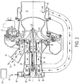
- an environmental control system (ECS) 10 for an aircraft includes one or more cabin air compressors (CACs) 12, which may be provided for example as centrifugal compressors.
- CACs cabin air compressors
- the CAC 12 compresses the airflow 14 and urges the airflow 14 from the compressor inlet 16 to a heat exchanger inlet 20, which may be provided as a part of a ram system 22, and an evaporator 24 and is then delivered to an aircraft cabin 26.
- Each CAC 12 is driven by a CAC motor 28 operably connected to the CAC 12 via a CAC shaft 30.
- the CAC motor 28 is an electric motor having a rotor 32 rotatably located at the CAC shaft 30 and a stator 36 having a plurality of stator windings 38 disposed radially outboard of the rotor 32.
- the CAC motor 28 also includes one or more bearings 40 disposed at the CAC shaft 30.
- a cooling flow is drawn across the CAC motor 28.
- the cooling flow is driven generally by a pressure drop from the compressor inlet 16 to the ram system 22, for example, ram fan inlet 21.
- the cooling flow includes a bearing cooling flow 42 and a motor cooling flow 44.
- the bearing cooling flow 42 is supplied via bearing cooling inlet 46 at a first end 48 of the CAC motor 28 opposite a second end 50 at which the CAC 12 is disposed.
- the bearing cooling flow 42 proceeds across thrust bearings 52 located at the first end 48, and across shaft bearings 54 located, for example, at the CAC shaft 30 at the first end 48 and/or the second end 50 to remove thermal energy from the thrust bearings 52 and the shaft bearings 54.
- the bearing cooling flow 42 exits the CAC motor 28 at a cooling flow exit 56, which may be defined as an opening between the CAC motor 28 and the CAC 12 that provides a cooling flow outlet.
- the CAC motor 28 includes a shroud 58 which directs the bearing cooling flow 42 radially inwardly toward the CAC shaft 30 to the cooling flow exit 56. After passing through the cooling flow exit 56, the bearing cooling flow 42 proceeds substantially radially outwardly through an exit channel 60 defined, in some embodiments, between the shroud 58 and a CAC rotor 62. The bearing cooling flow 42 is then directed to a cooling flow outlet at motor exit 64 toward, for example, the ram fan inlet 21.
- the motor cooling flow 44 is drawn from the compressor inlet 16, and enters the CAC motor 28 at a motor inlet 66 at the first end 48 via a cooling conduit.
- the motor cooling flow 44 proceeds through the CAC motor 28, substantially from the first end 48 to the second end 50 removing thermal energy from the stator windings 38 and other components of the CAC motor 28.
- the motor cooling flow 44 then proceeds through the cooling flow exit 56, the exit channel 60 and the motor exit 64 toward, for example, the ram fan inlet 21.
- the CAC 12 may include a compressor outlet 120, a sensor port 130, a sensor 140 and a sensor supply tube assembly 150.
- the compressor outlet 120 is provided at an end of an annular compartment of the CAC 12 and includes a tubular body that is formed to define a main flowpath 121 for compressed fluids.
- the sensor port 130 is coupled to the compressor outlet 120 and includes a tubular port body that is formed to define a sensor port flowpath 131.
- the sensor port flowpath 131 is oriented transversely with respect to the main flowpath 121 and is disposed and configured to direct a portion of main flowpath fluid from the main flowpath 121, along the sensor port flowpath 131 and to the sensor 140.
- the sensor 140 may be provided as a fluid pressure sensor 141 and is operably disposed at an end of the sensor port 130.
- the sensor 140 may include a flange 142 that is securable to an outer edge of the sensor port 130, a main body 143 and a sensor inlet 144.
- the sensor supply tube assembly 150 is non-rotatably disposable in the compressor outlet 120 and the sensor port 130 and is configured to direct the portion of the main flowpath fluid from the main flowpath 121 in the compressor outlet 120, along the sensor port flowpath 131 through a portion of the sensor port 130 and to the sensor inlet 144 of the sensor 140. More particularly, the sensor supply tube assembly 150 is configured to direct the portion of the main flowpath fluid along a first flowpath 145, along a second flowpath 146, which is oriented transversely with respect to the first flowpath 145, and along a curved flowpath 147. The curved flowpath 147 is interposed between the first and second flowpaths 145 and 146. With this configuration, the sensor supply tube assembly 150 provides resistance to the flow of debris from the main flowpath 121 to the sensor inlet 144 and thus reduces an amount of debris available to clog or otherwise foul the sensor 140.
- the sensor supply tube assembly 150 includes a first tube 160 and a second tube 170.
- the first tube 160 is formed to direct the main flowpath fluid from the main flowpath 121 in the compressor outlet 120 to the sensor inlet 144 of the sensor 140 through a portion of the sensor port 130.
- the first tube 160 includes a first tube first end 161, which is disposed within the sensor port 130, a first tube second end 162, which is disposed within the compressor outlet 120 and is oriented transversely with respect to the first tube first end 161, and a curved tube section 163.
- the curved tube section 163 is interposed between the first tube first end 161 and the second tube second end 162.
- the second tube 170 includes a sleeve element 171 and a base element 172.
- the sleeve element 171 is tightly fittable between an exterior surface of the first tube first end 161 and an interior surface of the sensor port 130.
- the base element 172 has an exterior surface 173 from which the sleeve element 171 extends and which is disposed and configured to non-rotatably abut with an interior surface 1201 of the compressor outlet 120.
- the base element 172 further includes an interior surface that faces the main flowpath 121.
- the curved tube section 163 terminates (i.e., transitions to the first tube first end 161) at the interior surface of the base element 172.
- the sleeve element 171 may be bonded to the exterior surface of the first tube first end 161. Such bonding may be achieved by way of welding, brazing or any other similar bonding process. Materials of the first tube 160 and the second tube 170 may be selected in accordance with at least a type of the bonding process.
- the first tube 160 of the sensor supply tube assembly 150 may have a J-shaped profile with a short leg facing in a downstream direction of the main flowpath 121.
- a wake generated by the sensor supply tube assembly 150 is relatively small as compared to an overall flow through the main flowpath 121 such that an aerodynamic impact of the sensor supply tube assembly 150 is limited.
- the sensor supply tube assembly 150 may further include a sensor fitting 180.
- a sensor fitting 180 may be interposed between a distal portion of the first tube first end 161 and the sensor inlet 144 of the sensor 140 and may be configured to limit leakage of fluid between the first tube 170 and the sensor 140.
- a distal portion of the sleeve element 171 may extend beyond the distal portion of the first tube first end 161 and, where applicable, the sensor fitting 180 to be engageable (e.g., threadably engageable) with an exterior surface of the sensor inlet 144.
- the exterior surface 173 of the base element 172 and the interior surface 1201 of the compressor outlet 120 may have respectively complementary curvatures 174 and 1202.
- the base element 172 may be tightly fittable to the interior surface 1201 in an anti-rotational configuration that provides the sensor supply tube assembly 150 with an ability to resist rotation about a longitudinal axis of the first tube first end 161, for example.
- the sensor fitting 180 may be attached to the distal portion of the first tube first end 161 and the sleeve element 171 is slid over the sensor fitting 180 and the exterior surface of the first tube first end 161. Subsequently, the exterior surface of the first tube first end 161 is bonded to the sleeve element 171 and the first tube first end 161, the sensor fitting 180 and the sleeve element 171 are inserted into the sensor port 130. At this point, the sensor 140 is installed by rotating the sensor 140 and thereby threadably engaging the sensor inlet 144 with the distal portion of the sleeve element 171. Such installation draws exterior surface 173 of the base element 172 toward the interior surface 1201 of the compressor outlet in a tightening manner and may include the additional installation of seals 190 between the sensor 140 and the sensor port 130.
Landscapes
- Engineering & Computer Science (AREA)
- Physics & Mathematics (AREA)
- Aviation & Aerospace Engineering (AREA)
- General Engineering & Computer Science (AREA)
- Mechanical Engineering (AREA)
- Health & Medical Sciences (AREA)
- Pulmonology (AREA)
- General Health & Medical Sciences (AREA)
- General Physics & Mathematics (AREA)
- Thermal Sciences (AREA)
- Fluid Mechanics (AREA)
- Structures Of Non-Positive Displacement Pumps (AREA)
- Compressor (AREA)
Applications Claiming Priority (1)
| Application Number | Priority Date | Filing Date | Title |
|---|---|---|---|
| US14/951,818 US10472072B2 (en) | 2015-11-25 | 2015-11-25 | Supply tube for sensor |
Publications (2)
| Publication Number | Publication Date |
|---|---|
| EP3173336A1 true EP3173336A1 (fr) | 2017-05-31 |
| EP3173336B1 EP3173336B1 (fr) | 2020-09-16 |
Family
ID=57394433
Family Applications (1)
| Application Number | Title | Priority Date | Filing Date |
|---|---|---|---|
| EP16200348.7A Active EP3173336B1 (fr) | 2015-11-25 | 2016-11-23 | Tube d'alimentation pour capteur |
Country Status (2)
| Country | Link |
|---|---|
| US (1) | US10472072B2 (fr) |
| EP (1) | EP3173336B1 (fr) |
Cited By (1)
| Publication number | Priority date | Publication date | Assignee | Title |
|---|---|---|---|---|
| EP4518113A1 (fr) * | 2023-08-29 | 2025-03-05 | Hamilton Sundstrand Corporation | Moteur électrique refroidi par air ayant un écoulement d'air accru et procédé pour augmenter l'écoulement d'air dans celui-ci |
Families Citing this family (5)
| Publication number | Priority date | Publication date | Assignee | Title |
|---|---|---|---|---|
| US10472072B2 (en) * | 2015-11-25 | 2019-11-12 | Hamilton Sundstrand Corporation | Supply tube for sensor |
| JP7529620B2 (ja) * | 2021-06-16 | 2024-08-06 | 三菱重工エンジン&ターボチャージャ株式会社 | 配管分岐装置及びコンプレッサ |
| US11661954B2 (en) * | 2021-09-08 | 2023-05-30 | Hamilton Sundstrand Corporation | Cabin air compressor with bleed scoop and removable bleed duct filter |
| US12055058B2 (en) * | 2022-05-31 | 2024-08-06 | Pratt & Whitney Canada Corp. | Joint between gas turbine engine components with a spring element |
| US12535034B1 (en) | 2024-09-27 | 2026-01-27 | Pratt & Whitney Canada Corp. | Joint between aircraft engine components with spring beams |
Citations (5)
| Publication number | Priority date | Publication date | Assignee | Title |
|---|---|---|---|---|
| GB1038139A (en) * | 1962-09-12 | 1966-08-10 | Narayan Pada Bhattacharjee | Connection union for fluid flow ducting |
| US3581565A (en) * | 1968-07-15 | 1971-06-01 | Peter D Dieterich | Flow-measuring device |
| US4498347A (en) * | 1983-03-31 | 1985-02-12 | Rockwell International Corporation | Fluid flow measuring |
| US5945606A (en) * | 1996-08-30 | 1999-08-31 | Desno Corporation | Elastic member, and method and structure for attaching sensor to sensor attachment member using the same |
| EP2377759A1 (fr) * | 2005-11-08 | 2011-10-19 | Hamilton Sundstrand Corporation | Soupape intégrée d'un compresseur pour la régulation de l'apport de chaleur et du pompage |
Family Cites Families (49)
| Publication number | Priority date | Publication date | Assignee | Title |
|---|---|---|---|---|
| US481310A (en) * | 1892-08-23 | Gage for measuring the velocity of fluids | ||
| US314323A (en) * | 1885-03-24 | Velooimetee for watee cueeents | ||
| US817470A (en) * | 1905-03-15 | 1906-04-10 | John A Cole | Pitot-tube connection. |
| US886255A (en) * | 1907-01-28 | 1908-04-28 | Sargent Steam Meter Company | Steam-meter. |
| US2768135A (en) * | 1953-08-04 | 1956-10-23 | Infilco Inc | Electrolytic cell |
| US3803921A (en) * | 1968-07-15 | 1974-04-16 | P Dieterich | Sampling and flow measuring device |
| US3691834A (en) * | 1970-08-21 | 1972-09-19 | Robert J De Fasselle | Variable area flow meter |
| US3876009A (en) * | 1972-01-28 | 1975-04-08 | Jr Wilber O Johnson | Fire extinguishing apparatus |
| US3937082A (en) * | 1974-09-06 | 1976-02-10 | Schilling Chilling Manufacturing Corporation | Gauge system for measuring air flow in ducts |
| US4482365A (en) | 1982-03-01 | 1984-11-13 | Pall Corporation | Vortex air cleaner and self-cleaning barrier filter assembly for supercharged engines |
| US4462204A (en) | 1982-07-23 | 1984-07-31 | General Electric Company | Gas turbine engine cooling airflow modulator |
| US4551069A (en) * | 1984-03-14 | 1985-11-05 | Copeland Corporation | Integral oil pressure sensor |
| US4793188A (en) * | 1986-01-14 | 1988-12-27 | Texas Instruments Incorporated | Lubrication sensor apparatus |
| US5209258A (en) * | 1987-03-02 | 1993-05-11 | Daniel Flow Products | Apparatus and method for minimizing pulsation-induced errors in differential pressure flow measuring devices |
| US4920740A (en) * | 1987-11-23 | 1990-05-01 | Sundstrand Corporation | Starting of turbine engines |
| DE3811616C1 (fr) * | 1988-04-07 | 1989-07-27 | Messerschmitt-Boelkow-Blohm Gmbh, 8012 Ottobrunn, De | |
| US5123240A (en) | 1990-03-19 | 1992-06-23 | General Electric Co. | Method and apparatus for ejecting foreign matter from the primary flow path of a gas turbine engine |
| US5131807A (en) * | 1990-07-16 | 1992-07-21 | Allied-Signal Inc. | Reverse pitot air filter |
| US5273407A (en) * | 1992-04-30 | 1993-12-28 | Apv Gaulin Gmbh | Homogenizing system having improved fluid flow path |
| US5567121A (en) * | 1995-01-23 | 1996-10-22 | Peterson; William C. | Indicator-ported discharge valves for reciprocating compressors |
| US7335164B2 (en) * | 1996-07-15 | 2008-02-26 | Ntc Technology, Inc. | Multiple function airway adapter |
| US5859589A (en) * | 1997-09-11 | 1999-01-12 | Mcgrew, Jr.; Henry E. | Pressure alarm and method of operation for sewage treatment system |
| JP4075129B2 (ja) * | 1998-04-16 | 2008-04-16 | 株式会社豊田自動織機 | 冷房装置の制御方法 |
| RU2152042C1 (ru) * | 1998-05-26 | 2000-06-27 | Центральный аэрогидродинамический институт им. проф. Н.Е. Жуковского | Приемник воздушного давления (варианты) |
| US6359377B1 (en) * | 1999-02-02 | 2002-03-19 | Savage Enterprises, Inc. | Spark plug with engine cylinder pressure sensor |
| CO5290359A1 (es) * | 1999-12-10 | 2003-06-27 | Coltec Ind Products Inc | Valvula para detectar por lo menos una condicion adentro de un compresor |
| US20010023613A1 (en) * | 2000-03-10 | 2001-09-27 | Gary Lemberger | Pressure gauge for vehicle tires |
| US6609733B2 (en) * | 2001-01-29 | 2003-08-26 | E-Z Flo Injection Systems, Inc. | Differential pressure fitting |
| US6926490B2 (en) * | 2003-01-21 | 2005-08-09 | Hamilton Sundstrand | Self-actuated bearing cooling flow shut-off valve |
| WO2006059987A1 (fr) * | 2004-12-01 | 2006-06-08 | United Technologies Corporation | Séparateur de particules pour moteur à turbine en bout |
| US7194920B2 (en) * | 2005-03-15 | 2007-03-27 | Welker Engineering Company | Sensor probe and pipeline construction and method |
| TWI291528B (en) * | 2005-07-28 | 2007-12-21 | Teng-Wen Huang | Two-way check valve |
| US7328623B2 (en) * | 2006-03-20 | 2008-02-12 | General Electric Company | Temperature and/or pressure sensor assembly |
| US7278320B1 (en) * | 2006-03-27 | 2007-10-09 | Honeywell International, Inc. | Omni-directional pressure pickup probe |
| US7597018B2 (en) * | 2007-04-11 | 2009-10-06 | Rosemount Aerospace Inc. | Pneumatic line isolation and heating for air data probes |
| CN102196837B (zh) * | 2008-08-22 | 2015-09-09 | 呼吸科技公司 | 利用开放的气道界面提供机械通气的方法和装置 |
| US8863548B2 (en) * | 2010-07-16 | 2014-10-21 | Hamilton Sundstrand Corporation | Cabin air compressor motor cooling |
| US8459966B2 (en) * | 2010-07-19 | 2013-06-11 | Hamilton Sundstrand Corporation | Ram air fan motor cooling |
| FR2973513B1 (fr) * | 2011-03-31 | 2013-04-12 | Thales Sa | Dispositif d'entretien et d'analyse de sonde aerodynamique |
| US20140202121A1 (en) * | 2012-06-18 | 2014-07-24 | Hamilton Sundstrand Corporation | Conical light fod momentum particle separator protector |
| US9243643B2 (en) * | 2012-07-27 | 2016-01-26 | Hamilton Sundstrand Corporation | Cabin air compressor housing |
| US8857255B2 (en) * | 2012-08-22 | 2014-10-14 | Rosemount Aerospace Inc. | Moisture resistant air data probes |
| US20140117103A1 (en) * | 2012-10-29 | 2014-05-01 | Mauro Antonio Rossi | Thermostat and housing for thermostat |
| GB2522847B (en) * | 2014-02-05 | 2017-02-22 | Rolls Royce Plc | Method and system for detecting a flow blockage in a pipe |
| EP2916120A1 (fr) * | 2014-03-04 | 2015-09-09 | seleon GmbH | Bloc de capteur, tube et procédé de fabrication |
| US11460366B2 (en) * | 2014-07-07 | 2022-10-04 | Energizer Auto, Inc. | Coupler and methods of use for assessment of refrigeration systems |
| DE102014115305A1 (de) * | 2014-10-21 | 2016-04-21 | Endress+Hauser Flowtec Ag | Thermisches Durchflussmessgerät |
| FR3039511B1 (fr) * | 2015-07-28 | 2017-09-08 | Thales Sa | Rechauffage pour equipement aeronautique d'aeronef |
| US10472072B2 (en) * | 2015-11-25 | 2019-11-12 | Hamilton Sundstrand Corporation | Supply tube for sensor |
-
2015
- 2015-11-25 US US14/951,818 patent/US10472072B2/en active Active
-
2016
- 2016-11-23 EP EP16200348.7A patent/EP3173336B1/fr active Active
Patent Citations (5)
| Publication number | Priority date | Publication date | Assignee | Title |
|---|---|---|---|---|
| GB1038139A (en) * | 1962-09-12 | 1966-08-10 | Narayan Pada Bhattacharjee | Connection union for fluid flow ducting |
| US3581565A (en) * | 1968-07-15 | 1971-06-01 | Peter D Dieterich | Flow-measuring device |
| US4498347A (en) * | 1983-03-31 | 1985-02-12 | Rockwell International Corporation | Fluid flow measuring |
| US5945606A (en) * | 1996-08-30 | 1999-08-31 | Desno Corporation | Elastic member, and method and structure for attaching sensor to sensor attachment member using the same |
| EP2377759A1 (fr) * | 2005-11-08 | 2011-10-19 | Hamilton Sundstrand Corporation | Soupape intégrée d'un compresseur pour la régulation de l'apport de chaleur et du pompage |
Cited By (2)
| Publication number | Priority date | Publication date | Assignee | Title |
|---|---|---|---|---|
| EP4518113A1 (fr) * | 2023-08-29 | 2025-03-05 | Hamilton Sundstrand Corporation | Moteur électrique refroidi par air ayant un écoulement d'air accru et procédé pour augmenter l'écoulement d'air dans celui-ci |
| US12531454B2 (en) | 2023-08-29 | 2026-01-20 | Hamilton Sundstrand Corporation | Air cooled electric motor having an increased airflow and a method for increasing the airflow therein |
Also Published As
| Publication number | Publication date |
|---|---|
| US20170144769A1 (en) | 2017-05-25 |
| EP3173336B1 (fr) | 2020-09-16 |
| US10472072B2 (en) | 2019-11-12 |
Similar Documents
| Publication | Publication Date | Title |
|---|---|---|
| EP3173336B1 (fr) | Tube d'alimentation pour capteur | |
| US7575421B2 (en) | Integral motor cooling and compressor inlet | |
| CN108368852B (zh) | 涡轮发动机或航空器的电动离心式压缩机 | |
| EP2711296B1 (fr) | Agencement de refroidissement pour ensemble moteur et procédé de refroidissement d'un ensemble moteur | |
| US8863548B2 (en) | Cabin air compressor motor cooling | |
| EP2617648B1 (fr) | Séparateur de particules carénées | |
| EP3184824B1 (fr) | Amélioration thermique du refroidissement d'un moteur de compresseur d'air de cabine | |
| US8734017B1 (en) | Air bearing shaft | |
| JP5961583B2 (ja) | 粒子分離器 | |
| EP3339175A1 (fr) | Circuit de refroidissement de moteur avec séparateur de particules de dommage par corps étranger | |
| US20140030070A1 (en) | Cabin air compressor housing | |
| EP2808257A1 (fr) | Ventilateur de refroidissement de moteur et structure de confinement | |
| US20140026993A1 (en) | Cabin air compressor heat housing | |
| US20160097401A1 (en) | Air cycle machine strut plate assembly | |
| EP3269946B1 (fr) | Dissipateur de chaleur de machine rotative | |
| US9914542B2 (en) | Ram air fan housing | |
| US9347455B2 (en) | Ejector assembly | |
| US10829241B2 (en) | Structurally improved ram fan inlet shroud | |
| US10443619B2 (en) | Motor housing assembly for a cabin air compressor | |
| CN107013267B (zh) | 空气循环机中的旁路壳体 | |
| US20170102002A1 (en) | Fan shaft for air cycle machine | |
| US12036498B2 (en) | Mid-pressure water collector (MPWC) with helical flow channel and radial scuppers |
Legal Events
| Date | Code | Title | Description |
|---|---|---|---|
| PUAI | Public reference made under article 153(3) epc to a published international application that has entered the european phase |
Free format text: ORIGINAL CODE: 0009012 |
|
| STAA | Information on the status of an ep patent application or granted ep patent |
Free format text: STATUS: THE APPLICATION HAS BEEN PUBLISHED |
|
| AK | Designated contracting states |
Kind code of ref document: A1 Designated state(s): AL AT BE BG CH CY CZ DE DK EE ES FI FR GB GR HR HU IE IS IT LI LT LU LV MC MK MT NL NO PL PT RO RS SE SI SK SM TR |
|
| AX | Request for extension of the european patent |
Extension state: BA ME |
|
| STAA | Information on the status of an ep patent application or granted ep patent |
Free format text: STATUS: REQUEST FOR EXAMINATION WAS MADE |
|
| 17P | Request for examination filed |
Effective date: 20171130 |
|
| RBV | Designated contracting states (corrected) |
Designated state(s): AL AT BE BG CH CY CZ DE DK EE ES FI FR GB GR HR HU IE IS IT LI LT LU LV MC MK MT NL NO PL PT RO RS SE SI SK SM TR |
|
| STAA | Information on the status of an ep patent application or granted ep patent |
Free format text: STATUS: EXAMINATION IS IN PROGRESS |
|
| 17Q | First examination report despatched |
Effective date: 20190528 |
|
| GRAP | Despatch of communication of intention to grant a patent |
Free format text: ORIGINAL CODE: EPIDOSNIGR1 |
|
| STAA | Information on the status of an ep patent application or granted ep patent |
Free format text: STATUS: GRANT OF PATENT IS INTENDED |
|
| INTG | Intention to grant announced |
Effective date: 20200403 |
|
| GRAS | Grant fee paid |
Free format text: ORIGINAL CODE: EPIDOSNIGR3 |
|
| GRAA | (expected) grant |
Free format text: ORIGINAL CODE: 0009210 |
|
| STAA | Information on the status of an ep patent application or granted ep patent |
Free format text: STATUS: THE PATENT HAS BEEN GRANTED |
|
| AK | Designated contracting states |
Kind code of ref document: B1 Designated state(s): AL AT BE BG CH CY CZ DE DK EE ES FI FR GB GR HR HU IE IS IT LI LT LU LV MC MK MT NL NO PL PT RO RS SE SI SK SM TR |
|
| RAP1 | Party data changed (applicant data changed or rights of an application transferred) |
Owner name: HAMILTON SUNDSTRAND CORPORATION |
|
| REG | Reference to a national code |
Ref country code: GB Ref legal event code: FG4D |
|
| REG | Reference to a national code |
Ref country code: CH Ref legal event code: EP |
|
| REG | Reference to a national code |
Ref country code: DE Ref legal event code: R096 Ref document number: 602016044023 Country of ref document: DE |
|
| REG | Reference to a national code |
Ref country code: IE Ref legal event code: FG4D |
|
| REG | Reference to a national code |
Ref country code: AT Ref legal event code: REF Ref document number: 1313965 Country of ref document: AT Kind code of ref document: T Effective date: 20201015 |
|
| PG25 | Lapsed in a contracting state [announced via postgrant information from national office to epo] |
Ref country code: GR Free format text: LAPSE BECAUSE OF FAILURE TO SUBMIT A TRANSLATION OF THE DESCRIPTION OR TO PAY THE FEE WITHIN THE PRESCRIBED TIME-LIMIT Effective date: 20201217 Ref country code: BG Free format text: LAPSE BECAUSE OF FAILURE TO SUBMIT A TRANSLATION OF THE DESCRIPTION OR TO PAY THE FEE WITHIN THE PRESCRIBED TIME-LIMIT Effective date: 20201216 Ref country code: SE Free format text: LAPSE BECAUSE OF FAILURE TO SUBMIT A TRANSLATION OF THE DESCRIPTION OR TO PAY THE FEE WITHIN THE PRESCRIBED TIME-LIMIT Effective date: 20200916 Ref country code: HR Free format text: LAPSE BECAUSE OF FAILURE TO SUBMIT A TRANSLATION OF THE DESCRIPTION OR TO PAY THE FEE WITHIN THE PRESCRIBED TIME-LIMIT Effective date: 20200916 Ref country code: FI Free format text: LAPSE BECAUSE OF FAILURE TO SUBMIT A TRANSLATION OF THE DESCRIPTION OR TO PAY THE FEE WITHIN THE PRESCRIBED TIME-LIMIT Effective date: 20200916 Ref country code: NO Free format text: LAPSE BECAUSE OF FAILURE TO SUBMIT A TRANSLATION OF THE DESCRIPTION OR TO PAY THE FEE WITHIN THE PRESCRIBED TIME-LIMIT Effective date: 20201216 |
|
| REG | Reference to a national code |
Ref country code: AT Ref legal event code: MK05 Ref document number: 1313965 Country of ref document: AT Kind code of ref document: T Effective date: 20200916 |
|
| REG | Reference to a national code |
Ref country code: NL Ref legal event code: MP Effective date: 20200916 |
|
| PG25 | Lapsed in a contracting state [announced via postgrant information from national office to epo] |
Ref country code: RS Free format text: LAPSE BECAUSE OF FAILURE TO SUBMIT A TRANSLATION OF THE DESCRIPTION OR TO PAY THE FEE WITHIN THE PRESCRIBED TIME-LIMIT Effective date: 20200916 Ref country code: LV Free format text: LAPSE BECAUSE OF FAILURE TO SUBMIT A TRANSLATION OF THE DESCRIPTION OR TO PAY THE FEE WITHIN THE PRESCRIBED TIME-LIMIT Effective date: 20200916 |
|
| REG | Reference to a national code |
Ref country code: LT Ref legal event code: MG4D |
|
| PG25 | Lapsed in a contracting state [announced via postgrant information from national office to epo] |
Ref country code: SM Free format text: LAPSE BECAUSE OF FAILURE TO SUBMIT A TRANSLATION OF THE DESCRIPTION OR TO PAY THE FEE WITHIN THE PRESCRIBED TIME-LIMIT Effective date: 20200916 Ref country code: PT Free format text: LAPSE BECAUSE OF FAILURE TO SUBMIT A TRANSLATION OF THE DESCRIPTION OR TO PAY THE FEE WITHIN THE PRESCRIBED TIME-LIMIT Effective date: 20210118 Ref country code: RO Free format text: LAPSE BECAUSE OF FAILURE TO SUBMIT A TRANSLATION OF THE DESCRIPTION OR TO PAY THE FEE WITHIN THE PRESCRIBED TIME-LIMIT Effective date: 20200916 Ref country code: CZ Free format text: LAPSE BECAUSE OF FAILURE TO SUBMIT A TRANSLATION OF THE DESCRIPTION OR TO PAY THE FEE WITHIN THE PRESCRIBED TIME-LIMIT Effective date: 20200916 Ref country code: LT Free format text: LAPSE BECAUSE OF FAILURE TO SUBMIT A TRANSLATION OF THE DESCRIPTION OR TO PAY THE FEE WITHIN THE PRESCRIBED TIME-LIMIT Effective date: 20200916 Ref country code: EE Free format text: LAPSE BECAUSE OF FAILURE TO SUBMIT A TRANSLATION OF THE DESCRIPTION OR TO PAY THE FEE WITHIN THE PRESCRIBED TIME-LIMIT Effective date: 20200916 |
|
| RAP4 | Party data changed (patent owner data changed or rights of a patent transferred) |
Owner name: HAMILTON SUNDSTRAND CORPORATION |
|
| PG25 | Lapsed in a contracting state [announced via postgrant information from national office to epo] |
Ref country code: AT Free format text: LAPSE BECAUSE OF FAILURE TO SUBMIT A TRANSLATION OF THE DESCRIPTION OR TO PAY THE FEE WITHIN THE PRESCRIBED TIME-LIMIT Effective date: 20200916 Ref country code: AL Free format text: LAPSE BECAUSE OF FAILURE TO SUBMIT A TRANSLATION OF THE DESCRIPTION OR TO PAY THE FEE WITHIN THE PRESCRIBED TIME-LIMIT Effective date: 20200916 Ref country code: ES Free format text: LAPSE BECAUSE OF FAILURE TO SUBMIT A TRANSLATION OF THE DESCRIPTION OR TO PAY THE FEE WITHIN THE PRESCRIBED TIME-LIMIT Effective date: 20200916 Ref country code: IS Free format text: LAPSE BECAUSE OF FAILURE TO SUBMIT A TRANSLATION OF THE DESCRIPTION OR TO PAY THE FEE WITHIN THE PRESCRIBED TIME-LIMIT Effective date: 20210116 Ref country code: PL Free format text: LAPSE BECAUSE OF FAILURE TO SUBMIT A TRANSLATION OF THE DESCRIPTION OR TO PAY THE FEE WITHIN THE PRESCRIBED TIME-LIMIT Effective date: 20200916 |
|
| REG | Reference to a national code |
Ref country code: DE Ref legal event code: R119 Ref document number: 602016044023 Country of ref document: DE |
|
| PG25 | Lapsed in a contracting state [announced via postgrant information from national office to epo] |
Ref country code: MC Free format text: LAPSE BECAUSE OF FAILURE TO SUBMIT A TRANSLATION OF THE DESCRIPTION OR TO PAY THE FEE WITHIN THE PRESCRIBED TIME-LIMIT Effective date: 20200916 Ref country code: SK Free format text: LAPSE BECAUSE OF FAILURE TO SUBMIT A TRANSLATION OF THE DESCRIPTION OR TO PAY THE FEE WITHIN THE PRESCRIBED TIME-LIMIT Effective date: 20200916 |
|
| REG | Reference to a national code |
Ref country code: CH Ref legal event code: PL |
|
| PLBE | No opposition filed within time limit |
Free format text: ORIGINAL CODE: 0009261 |
|
| STAA | Information on the status of an ep patent application or granted ep patent |
Free format text: STATUS: NO OPPOSITION FILED WITHIN TIME LIMIT |
|
| PG25 | Lapsed in a contracting state [announced via postgrant information from national office to epo] |
Ref country code: LU Free format text: LAPSE BECAUSE OF NON-PAYMENT OF DUE FEES Effective date: 20201123 |
|
| REG | Reference to a national code |
Ref country code: BE Ref legal event code: MM Effective date: 20201130 |
|
| 26N | No opposition filed |
Effective date: 20210617 |
|
| PG25 | Lapsed in a contracting state [announced via postgrant information from national office to epo] |
Ref country code: SI Free format text: LAPSE BECAUSE OF FAILURE TO SUBMIT A TRANSLATION OF THE DESCRIPTION OR TO PAY THE FEE WITHIN THE PRESCRIBED TIME-LIMIT Effective date: 20200916 Ref country code: LI Free format text: LAPSE BECAUSE OF NON-PAYMENT OF DUE FEES Effective date: 20201130 Ref country code: DK Free format text: LAPSE BECAUSE OF FAILURE TO SUBMIT A TRANSLATION OF THE DESCRIPTION OR TO PAY THE FEE WITHIN THE PRESCRIBED TIME-LIMIT Effective date: 20200916 Ref country code: CH Free format text: LAPSE BECAUSE OF NON-PAYMENT OF DUE FEES Effective date: 20201130 |
|
| PG25 | Lapsed in a contracting state [announced via postgrant information from national office to epo] |
Ref country code: IT Free format text: LAPSE BECAUSE OF FAILURE TO SUBMIT A TRANSLATION OF THE DESCRIPTION OR TO PAY THE FEE WITHIN THE PRESCRIBED TIME-LIMIT Effective date: 20200916 Ref country code: IE Free format text: LAPSE BECAUSE OF NON-PAYMENT OF DUE FEES Effective date: 20201123 |
|
| PG25 | Lapsed in a contracting state [announced via postgrant information from national office to epo] |
Ref country code: DE Free format text: LAPSE BECAUSE OF NON-PAYMENT OF DUE FEES Effective date: 20210601 |
|
| PG25 | Lapsed in a contracting state [announced via postgrant information from national office to epo] |
Ref country code: IS Free format text: LAPSE BECAUSE OF FAILURE TO SUBMIT A TRANSLATION OF THE DESCRIPTION OR TO PAY THE FEE WITHIN THE PRESCRIBED TIME-LIMIT Effective date: 20210116 Ref country code: TR Free format text: LAPSE BECAUSE OF FAILURE TO SUBMIT A TRANSLATION OF THE DESCRIPTION OR TO PAY THE FEE WITHIN THE PRESCRIBED TIME-LIMIT Effective date: 20200916 Ref country code: MT Free format text: LAPSE BECAUSE OF FAILURE TO SUBMIT A TRANSLATION OF THE DESCRIPTION OR TO PAY THE FEE WITHIN THE PRESCRIBED TIME-LIMIT Effective date: 20200916 Ref country code: CY Free format text: LAPSE BECAUSE OF FAILURE TO SUBMIT A TRANSLATION OF THE DESCRIPTION OR TO PAY THE FEE WITHIN THE PRESCRIBED TIME-LIMIT Effective date: 20200916 |
|
| PG25 | Lapsed in a contracting state [announced via postgrant information from national office to epo] |
Ref country code: MK Free format text: LAPSE BECAUSE OF FAILURE TO SUBMIT A TRANSLATION OF THE DESCRIPTION OR TO PAY THE FEE WITHIN THE PRESCRIBED TIME-LIMIT Effective date: 20200916 |
|
| PG25 | Lapsed in a contracting state [announced via postgrant information from national office to epo] |
Ref country code: BE Free format text: LAPSE BECAUSE OF NON-PAYMENT OF DUE FEES Effective date: 20201130 |
|
| P01 | Opt-out of the competence of the unified patent court (upc) registered |
Effective date: 20230522 |
|
| PG25 | Lapsed in a contracting state [announced via postgrant information from national office to epo] |
Ref country code: NL Free format text: LAPSE BECAUSE OF NON-PAYMENT OF DUE FEES Effective date: 20200923 |
|
| PGFP | Annual fee paid to national office [announced via postgrant information from national office to epo] |
Ref country code: GB Payment date: 20251023 Year of fee payment: 10 |
|
| PGFP | Annual fee paid to national office [announced via postgrant information from national office to epo] |
Ref country code: FR Payment date: 20251023 Year of fee payment: 10 |