EP2712652A2 - Medizinisches Verbindungssystem mit Aufschraubblockierung - Google Patents
Medizinisches Verbindungssystem mit Aufschraubblockierung Download PDFInfo
- Publication number
- EP2712652A2 EP2712652A2 EP13186397.9A EP13186397A EP2712652A2 EP 2712652 A2 EP2712652 A2 EP 2712652A2 EP 13186397 A EP13186397 A EP 13186397A EP 2712652 A2 EP2712652 A2 EP 2712652A2
- Authority
- EP
- European Patent Office
- Prior art keywords
- connector
- housing
- connection
- longitudinal axis
- connection system
- Prior art date
- Legal status (The legal status is an assumption and is not a legal conclusion. Google has not performed a legal analysis and makes no representation as to the accuracy of the status listed.)
- Granted
Links
Images





Classifications
-
- A—HUMAN NECESSITIES
- A61—MEDICAL OR VETERINARY SCIENCE; HYGIENE
- A61M—DEVICES FOR INTRODUCING MEDIA INTO, OR ONTO, THE BODY; DEVICES FOR TRANSDUCING BODY MEDIA OR FOR TAKING MEDIA FROM THE BODY; DEVICES FOR PRODUCING OR ENDING SLEEP OR STUPOR
- A61M39/00—Tubes, tube connectors, tube couplings, valves, access sites or the like, specially adapted for medical use
- A61M39/10—Tube connectors; Tube couplings
- A61M39/1011—Locking means for securing connection; Additional tamper safeties
Definitions
- the invention generally relates to a medical connection system, adapted to connect a first medical device and a second medical device.
- the catheters and associated circuits comprising means of connection by screwing, are likely to unintentionally unscrew, either when they are in place, in particular on a patient, or during their transport.
- the circuits can be very simple, and in particular correspond to a syringe connected to a catheter, or complex, as is the case of oncology circuits for the simultaneous or sequential infusion of several drugs by means of pumps, pockets or even drop by drop and / or gravity.
- the accidental unscrewing of these circuits can have serious consequences, such as creating air inlets to the patient, stop infusions, disconnect medical devices, distort therapies, etc.
- the document US 2012/0157914 discloses a connector comprising a distal connector, a housing, a proximal connector, and a sealing member.
- the distal connector is secured with threads on the housing while the proximal connector is snap-fastened with a tab.
- the accidental unscrewing of one or the other of the end pieces which are screwed on the connections is possible, whether voluntarily or accidentally.
- the document WO 00/62844 also discloses a connector comprising a distal connector, a housing, a proximal connector, and a sealing member.
- the distal connector is secured to the housing by screwing and is held in this housing by bonding a retaining ring, while the proximal connector can be rotatable in the housing or secured to the housing with threads.
- the disconnection of a screwed end on one and / or the other of the connections is possible, voluntarily or accidentally.
- a medical connector comprising a proximal connector adapted to be connected to a threaded end, a casing adapted to house the proximal connector and comprising means for locking in rotation of the proximal connection only in the screwing direction of the endpiece, and a distal connection, movable in rotation in the housing and in which is inserted by force a conduit.
- This connector is likely to prevent unscrewing of the threaded end.
- the rotation in the screwing direction of this threaded end can dislodge the conduit of the housing, and thus allow its removal from the connector.
- a bad assembly of a circuit can lead to problems of operation, such as an impossibility of purging to completely expel the air, problems of reductions of flow, dead volumes too big or badly known, or the losses of expensive drug products, etc.
- An object of the invention is therefore to provide a medical connection system, for connecting one or more medical devices by screwing, which is capable of preventing accidental unscrewing of the device or devices connected to it, whatever the materials used for medical devices, and which is also low cost and simple to achieve.
- the invention also aims to prevent any unscrewing of the medical device (s), and to use, if necessary, an adapter in order to transform a screw connection of a given type into a connection of a different type, without risk of subsequent disassembly.
- a medical connection system 1 according to the invention will now be described in connection with the accompanying figures, in the context of a fluid connection system, that is to say a system allowing fluidically communicating with sealing a first medical device with a second medical device.
- a fluid connection system that is to say a system allowing fluidically communicating with sealing a first medical device with a second medical device.
- This is however not limiting, insofar as the system can be implemented in the context of a connection without sealing.
- the first connector may for example be a male connector 10
- the second connector may be a female connector 20.
- the male connector 10 defines a coaxial passage with a longitudinal axis X, and comprises a threaded distal tip 11 and a proximal endpiece.
- the female connector 20 in turn defines a passage coaxial with this longitudinal axis X, and comprises a threaded proximal endpiece 22, and a distal tip.
- Each of the threaded ends 11, 22 of the male and female connectors 20 is adapted to be connected to a respective medical device, comprising complementary screw connection means.
- complementary screw connection means For example, they may be standard Luer Lock connections.
- the screwing direction of the distal tip 11 of the male connector 10 is opposite to the screwing direction of the proximal endpiece 22 of the female connector 20.
- the distal tip 11 of the male connector 10 is of the male Luer Lock type, while the proximal end 22 of the female connector 20 is of the female Luer Lock type.
- the distal tip 11 of the male connector 10 may be a female end, while the proximal end 22 of the female connector 20 may be a male end.
- the distal 11 and proximal 22 threaded tips may also be male or female.
- proximal will designate a part (for example a tip) which is located near an operator, while “distal” will designate a part that is remote from the operator. In the figures, the operator is on the right side.
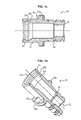
- the proximal endpiece 12 of the male connector 10 has a generally tubular shape, and is adapted to be introduced, preferably with sealing, into the corresponding distal tip of the female connector 20.
- an outer diameter of the proximal endpiece 12 of male connector 10 is substantially equal to the internal diameter of the distal tip 21 of the female connector 20.
- the sealing of the connection of the male connector 10 and the female connector 20 can be improved by interposing between the proximal endpiece 12 of the male connector 10 and the distal end 21 of the female connector 20 a sealing member 13 adapted to be compressed locally between the two ends 12, 21.
- the proximal end 12 of the male connector 10 may include a local sealing allowance 13, which may for example be annular.
- the proximal endpiece 12 of the male connector 10 is smooth, the excess thickness being made on the inner face of the distal tip 21 of the female connector 20. In both embodiments, the extra thickness 13 may be formed integrally with the tip concerned, or reported.
- the tubular shape of the proximal endpiece 12 of the male connector 10 and of the distal tip 21 of the female connector 20 also makes it possible to guide the male connector 10 when it is introduced into the female connector 20.
- the male connector 10 and the female connector 20 further comprise coupling means 14, 23, allowing their mutual connection without preventing their relative rotation. More specifically, the coupling means 14, 23 may be latching means 14, 23 arranged to allow the insertion and then the blocking of the male connector 10 in the female connector 20, thus preventing any subsequent separation of the connectors 10, 20, and allow the relative rotation of the male connector 10 and the female connector 20.
- the latching means 14, 23 may comprise a support 23 made in an inner surface of the distal tip 21 of the female connector 20, adapted to cooperate with a collar 14 projecting from an outer surface of the endpiece. proximal 12 of the male connector 10.
- the flange 14 may have a cross section of generally triangular shape, with a slope inclined 14a in the proximal direction, interrupted so as to form a transverse straight edge 14b. In this way, the thickness of the flange 14 increases progressively in distal direction to its right edge 14b, thus facilitating the introduction of the support 23 through the slope 14a forming a guide surface, and its retention with its right edge 14b.
- the support 23 may be disposed at the free end of the distal tip 21 of the female connector 20, and form if necessary an annular extra thickness.
- the proximal endpiece 12 of the male connector 10 is then introduced into the distal tip 21 of the female connector 20, and guided into the female connector 20 along the axis longitudinal X until the support 23 of the female connector 20 is in abutment against the inclined slope 14a of the collar 14.
- the support 23 By pushing on the male connector 10 towards the female connector 20, the support 23 then tends to move slightly apart, allowing it to slide along the inclined slope 14a as the male connector 10 is depressed into the female connector 20 until it reaches the transverse right edge 14b.
- the support 23 then folds downstream of the collar 14. It is no longer possible to separate the two connections 10, 20.
- the support 23 comes into abutment against the right edge 14b of the flange 14, and can not deviate 30 of itself to cross it (since there is not, in this sense, inclined slope 14a ).
- the wall of the distal tip 21 of the female connector 20 may be locally thinned upstream of the support 23, in an adjacent zone 23b of this, so as to increase the elasticity of the free end of the nozzle and facilitate the separation of the support 23 during the passage of the flange 14.
- the flange 14 then comes to be lodged against the portion 23b locally thinned of the wall of the proximal endpiece 21.
- the proximal endpiece 12 of the male connector 10 and the distal tip 21 of the female connector 20 may comprise means forming a stop, adapted to cooperate together once the male connector 10 coupled to the female connector 20 by means of latching means 14, 23.
- this stop function is played by the latching means 14, 23 themselves.
- the wall of the distal tip 21 may have, upstream of the thinned portion, an inclined portion 23a adapted to cooperate with the inclined slope 14a of the flange 14.
- the support 23 is positioned downstream of the flange 14, which is housed in the groove generated by the local thinning 23b of the wall, so that the inclined slope 14a of the flange 14 is is positioned facing the inclined wall 23a.
- this role of abutment can be played by the contact between the proximal end of the proximal endpiece 12 of the male connector 10 and an excess thickness 24 of the inner wall of the distal tip 21 of the female connector 20 .
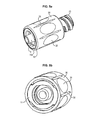
- the housing 30 comprises a generally tubular wall adapted to at least partially accommodate the male connector 10 and the female connector 20 and hold them in position.
- the housing 30 may in particular be fitted on the male connector 10 and the female connector 20, so as to allow their relative rotation about the longitudinal axis X, while limiting their displacement along the longitudinal axis X.
- the casing 30 further comprises means for locking in rotation the male connector 10 and the female connector 20 around the longitudinal axis X in the screwing direction of their endpiece. respective threads.
- the locking means are capable of locking in rotation the male connector 10 in the screwing direction of its distal tip only, and in parallel the female connector 20 in the screwing direction of its proximal tip only, the screwing direction the distal tip 11 of the male connector 10 being opposite to the screwing direction of the proximal endpiece 22 of the female connector 20.
- the locking means are capable of locking in rotation the male connector 10 in the screwing direction of its distal tip only, and in parallel the female connector 20 in the screwing direction of its proximal tip only, the screwing direction the distal tip 11 of the male connector 10 being opposite to the screwing direction of the proximal endpiece 22 of the female connector 20.
- none of the connections 10, 20 is accessible. without dismantling the connection system 1, and can not be grasped by the operator since they are both housed for the most part in the housing 30.
- the rotational locking means of the housing 30 each comprise at least one notch 33, adapted to cooperate with a tooth 15, 25 made in the fitting 10, 20 corresponding.
- the locking means each comprise two teeth 15, 25, extending from the corresponding connector 10, 20, and at least as many notches 33, for example four for each connector 10, 20.
- the casing 30 comprises recesses 31, 32 in its inner wall, at its proximal and distal ends, and the male and female connectors 20 comprise a corresponding thickness 15a, 25a corresponding at the end of their connection. distal 11 and proximal 21 respectively.
- the extra thickness 15a of the male connector 10 has a generally tubular shape, projecting along the periphery of the distal tip 11 of the male connector 10, of which at least one tooth 15, here two teeth, extends in the direction of the spigot. proximal end 12 of the connector 10.
- Each tooth 15 has a locking edge 15b substantially parallel to the longitudinal axis X and a guide edge 15c, extending continuously between a first free end of the locking edge 15b and the extra thickness 15a.
- the excess thickness 25a of the female connector 20 has a generally tubular shape, projecting along the periphery of the proximal endpiece 22 of the female connector 20, of which at least one tooth 25 extends, here two teeth 25 in the direction of the distal tip 21 of the connector 20.
- Each tooth 25 has a locking edge 25b substantially parallel to the longitudinal axis X and a guide edge 25c extending continuously between a first free end of the locking edge 25a and the excess thickness 25a.
- Each tooth 15, 25 can be integrally formed with the extra thickness 15a, 25a, itself being integral with the rest of the fitting 10, 20 corresponding.
- each recess 31, 32 of the housing 30 is of generally annular shape, and is delimited by an edge 33a adapted to abut against the extra thickness 15a, 25a opposite (that is to say the extra thickness 15a of the fitting male 10 in the case of the distal recess 31, and the extra thickness 25a of the female connector 20 in the case of the proximal reinforcement 32).
- the edge 33a of the recess 31, 32 defines a notch 33, triangular shape complementary to the shape of the teeth 15, 25, and adapted to optionally receive a tooth 15, 25 when connecting a medical device to the medical connection system 1.
- the notch 33 is formed of a locking edge 33b, substantially parallel to the longitudinal axis X, and a guide edge 33c, extending continuously between one end of the edge blocking 33b and the edge 33a of the recess 31, 32, along the periphery of the housing 30.
- the guide edge 33b of a given notch 33 may for example extend between the free end of the corresponding locking edge 33c and the base of the 33b locking edge of the notch 33 adjacent.
- An internal diameter of the inner wall of the housing 30 at the proximal recesses 32 and distal 31 is furthermore substantially equal to the outer diameter of the extra thicknesses 15a, 25a of the male and female connectors 20, in order to guarantee their engagement during operation. a possible connection.
- the internal diameter of the inner wall of the housing 30 in the central zone 34 located between the two recesses 31, 32 is smaller, and is at least equal to the external diameter of the distal tip 11 of the male connector 10 and the proximal endpiece 22 of the female connector 20.
- the dimensions, and in particular the length of the casing 30 is also chosen so that, when housing the male connector 10 and the female connector 20 and the connectors 10, 20 are coupled, only their respective threaded ends 11, 22 are possibly able to protrude outside the housing 30, these tips 11, 22 being intended to be concealed in the corresponding tips of the medical devices when they are connected to these devices.
- the housing 30 is the only part of the connection system 1 that can be manipulated by the operator. It may therefore comprise gripping means improving the handling of the casing 30 by the operator, formed for example by concave impressions 35 made in its outer surface, and / or longitudinal grooves 36 protruding from the outer wall.
- the housing 30 houses the entire distal tip 11 of the male connector 10 and the proximal endpiece 22 of the female connector 20, only the threads of the proximal endpiece 22 and possibly the tubular portion of the distal tip 11 not being covered.
- the proximal endpiece 22 of the female connector 20 is connected to a male end, here of the Luer Lock® type, and thus covered by the threaded collar complementary to this male end, while the distal tip 11 of the male connector 10 is connected to a female end, also Luer Lock® type.
- the proximal tip 22 is no longer accessible.
- the collar of the distal tip 11 in turn can be concealed by the housing 30, if it is long enough to cover it, which prevents an operator to keep it fixed in rotation to unscrew the device connected to it.
- the guide edges 33c of the notches 33 of the distal recess 31 and those of the proximal recess 32 extend substantially parallel.
- the hollow of the notches 33 of the proximal recess 32 are thus opposed to the recesses of the notches 33 of the distal recess 31 of the housing 30.
- the medical connection system 1 then comprises, when all the parts that compose it are assembled, the male connector 10 and the female connector 20, coupled so as to be able to rotate with respect to each other, and substantially fixed in translation, housed in the housing 30.
- the housing 30 may for example be fitted on one of the connectors 10, 20, say the female connector 20, by positioning the teeth 25 of the female connector 20 opposite corresponding notches 33 of the housing 30.
- the female connector 20 is preferably positioned in abutment in the housing 30, by inserting the teeth 25 of the connector 20 in corresponding notches 33 of the housing 30.
- the male connector 10 can then be introduced into the housing 30 and the female connector 20.
- the proximal endpiece 12 of the male connector 10 is introduced gradually into the housing 30, by its distal end, so that its proximal endpiece 12 penetrates into the distal tip 21 of the female connector 20.
- the collar 14 of the distal tip 11 of the male connector 10 abuts against the support 23 of the proximal endpiece 22 of the female connector 20, then it is sufficient to exert a slight effort on the connections 10, 20 so that the flange 14 moves the support 23 and that it is housed behind the collar 14.
- the male connector 10 and the female connector 20 are then coupled by the cooperation of their latching means 14, 23 in the housing 30.
- the housing 30 is first fitted on the male connector 10, then the female connector 20 is positioned by inserting it through the proximal end of the housing 30.
- the latching means 14, 23 of the male connector 10 and the female connector 20 prevent any separation of the connectors 10, 20 Furthermore, since the internal diameter of the central zone 34 of the casing 30 is smaller than that of the extra thicknesses 15a, 25a of the connectors 10, 20 which bear the teeth 15, 25, neither of the two connectors 10, 20 is capable of pass, the latter being blocked by the edges 31a, 32a of the recesses 31, 32 of the housing 30.
- the female connector 20 and the male connector 10 may be provided with visual markers 16, 26 serving as an aid for the relative positioning of the male connector 10 and the female connector 20 relative to the housing 30.
- the connectors 10, 20 may have grooves 16, 26, made in the surface 15d, 25d of the the grooves 15, 25a which is opposed to the teeth 15, 25.
- the grooves 16, 26 may in particular be arranged on the surface 15d, 25d relative to the teeth 15, 25 so that it is sufficient for the operator to place the grooves 16 of the male connector 10 opposite the grooves 26 of the connector female 20 during the introduction of the male connector 10 in the housing 30 and the female connector 20.
- the female connector 20 is already introduced into the housing 30 fixedly, and preferably in the notches 33 of the proximal recess 32 by positioning the male connector 10 with respect to the female connector 20, it is also positioned relative to the housing 30.
- the medical connection system 1 is now ready for use. If an operator wants to connect without risk of inadvertent unscrewing of medical devices, it is then sufficient to screw them on both sides of the system 1.
- the operator can screw a first device with a male Luer Lock® tip on the proximal end 22 of the female connector 20 (which is here a female Luer Lock® tip).
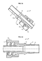
- the operator grasps the connection system 1 by its housing 30, and positions the male end in the female end 22 of the female connector 20. It is then naturally necessary to push on the male end and the connector 20, which causes the female connector 20 to abut against the edge 32a of the recess 32 proximal 32 of the housing 30 ( figure 5d ).
- the particular shape of the recess 32 guides the female connector 20, thanks to the guide edges 25c, 33c of the teeth 25 and notches 33 opposite and rotate the connector 20 relative to the housing 30 until the teeth 25 penetrate into the housing. Notches 33.
- connection of a second device this time provided with a female Luer Lock tip on the distal tip 11 of the male connector 10 (which is here a male Luer Lock connector).
- the operator enters the connection system 1, which can already be attached to the first medical device, by the casing 30, positions the socket in the male end 11 of the male connector 10, and pushes on the female end towards the connector 10.
- the male connector 10 is moved along of the longitudinal axis X until it abuts against the edge 31a of the distal recess 31 of the housing 30. Note that it is the assembly formed of the male connector 10 coupled to the female connector 20 which moves in the housing 30, since their latching means 14, 23 does not allow substantial relative translation.
- the particular shape of the recess 31 guides the male connector 10, thanks to the guide edges 15c, 33c of the teeth 15 and notches 33 opposite, until the teeth 15 penetrate into notches 33.
- the locking edges 15b of the teeth 15 then come into abutment against the locking edges 33b of the notches 33, stopping the rotation of the male connector 10 with respect to the casing 30.
- By continuing the rotational movement of the socket of the second medical device relative to the casing 30 it can then screw the female end to the male end 11 of the male connector 10, which is now fixed in rotation relative to the housing 30.
- the tip of the male connector 10 and that of the female connector 20 may be of different types (while preferably remaining screw-on bits).
- the connection system 1 therefore allows the connection of two devices having different connection means, and can thus advantageously serve as a connection adapter.
- circuits already mounted for example comprising two medical devices connected via a connection system 1 according to the invention, without the risk of unscrewing. accidental, whatever the conditions of transport or use of the circuit.
- the medical connection system 1 may comprise only one connection, male or female.
- the connection system then comprises retaining means in translation of the connection in the housing, capable of limiting the movements of the connection in the housing along the longitudinal axis X, while allowing their rotation relative to the housing .
- retaining means in translation of the connection in the housing, capable of limiting the movements of the connection in the housing along the longitudinal axis X, while allowing their rotation relative to the housing .
- the connection in order to allow the teeth to slide on the guide edges of the notches when the connection is rotated in its unscrewing direction, it is necessary that the connection can move along the longitudinal axis X so that the teeth can not come into contact with the locking edges.
- the fitting must be retained in the housing if it is desired to prevent the operator from grasping the fitting, as far as this would allow it to be unscrewed.
- the role of the retaining means is played by the second connection.
- the latching means of the connectors allow their relative rotation, and the collaboration of the extra thickness of the connection with the corresponding recess of the housing makes it possible to limit the translations of the connections along the longitudinal axis X.
- the retaining means may comprise snap-fastening means formed of a flange and a support, adapted to cooperate similarly to what has been described above, the support being slidable over a distance substantially equal to the length of the locking edges of the teeth of the coupling once the means interlocking snaps.
Landscapes
- Health & Medical Sciences (AREA)
- Heart & Thoracic Surgery (AREA)
- Pulmonology (AREA)
- Engineering & Computer Science (AREA)
- Anesthesiology (AREA)
- Biomedical Technology (AREA)
- Hematology (AREA)
- Life Sciences & Earth Sciences (AREA)
- Animal Behavior & Ethology (AREA)
- General Health & Medical Sciences (AREA)
- Public Health (AREA)
- Veterinary Medicine (AREA)
- Infusion, Injection, And Reservoir Apparatuses (AREA)
Applications Claiming Priority (1)
| Application Number | Priority Date | Filing Date | Title |
|---|---|---|---|
| FR1259159A FR2996141B1 (fr) | 2012-09-28 | 2012-09-28 | Systeme de connexion medicale anti-devissage |
Publications (3)
| Publication Number | Publication Date |
|---|---|
| EP2712652A2 true EP2712652A2 (de) | 2014-04-02 |
| EP2712652A3 EP2712652A3 (de) | 2017-08-30 |
| EP2712652B1 EP2712652B1 (de) | 2021-05-26 |
Family
ID=47257963
Family Applications (1)
| Application Number | Title | Priority Date | Filing Date |
|---|---|---|---|
| EP13186397.9A Active EP2712652B1 (de) | 2012-09-28 | 2013-09-27 | Medizinisches Verbindungssystem mit Aufschraubblockierung |
Country Status (3)
| Country | Link |
|---|---|
| EP (1) | EP2712652B1 (de) |
| ES (1) | ES2883216T3 (de) |
| FR (1) | FR2996141B1 (de) |
Cited By (11)
| Publication number | Priority date | Publication date | Assignee | Title |
|---|---|---|---|---|
| JP2017148444A (ja) * | 2016-02-26 | 2017-08-31 | 株式会社トップ | 医療用コネクタ |
| CN109069343A (zh) * | 2016-01-21 | 2018-12-21 | 泰瓦医药有限公司 | 鲁尔锁适配器 |
| WO2019130891A1 (ja) * | 2017-12-26 | 2019-07-04 | テルモ株式会社 | 医療用コネクタ |
| WO2020066938A1 (ja) * | 2018-09-27 | 2020-04-02 | 株式会社ジェイ・エム・エス | コネクタ |
| CN111110965A (zh) * | 2018-10-31 | 2020-05-08 | 深圳市大雅医疗技术有限公司 | 一种可加热呼吸管及呼吸机 |
| WO2021124727A1 (ja) * | 2019-12-20 | 2021-06-24 | テルモ株式会社 | 医療用コネクタ |
| FR3110440A1 (fr) * | 2020-05-19 | 2021-11-26 | Vygon | Raccord présentant des ailettes de préhension pour une ligne de nutrition |
| WO2022185313A1 (en) * | 2021-03-03 | 2022-09-09 | Equashield Medical Ltd. | A tamper proof luer lock connector and a valve arrangement for an adaptor |
| US20220296870A1 (en) * | 2019-08-13 | 2022-09-22 | Gambro Lundia Ab | Non-removable connection system |
| CN115243754A (zh) * | 2020-03-06 | 2022-10-25 | B·布莱恩·梅尔松根股份公司 | 用于封闭流体输送系统的联接系统 |
| US20230372691A1 (en) * | 2021-02-24 | 2023-11-23 | Terumo Kabushiki Kaisha | Conversion adapter, connector set, and assembly |
Families Citing this family (1)
| Publication number | Priority date | Publication date | Assignee | Title |
|---|---|---|---|---|
| FR3056917B1 (fr) | 2016-09-30 | 2022-02-11 | Vygon | Systeme d'introduction d'un catheter dans une veine |
Citations (3)
| Publication number | Priority date | Publication date | Assignee | Title |
|---|---|---|---|---|
| WO2000062844A1 (en) | 1999-04-16 | 2000-10-26 | Merit Medical Systems, Inc. | Inline hemostatis valve |
| US20080172039A1 (en) | 2006-10-02 | 2008-07-17 | B. Braun Medical Inc. | Ratcheting luer lock connector |
| US20120157914A1 (en) | 2010-12-15 | 2012-06-21 | Infusion Innovations, Inc. | Devices, Assemblies and Methods for Controlling Fluid Flow |
Family Cites Families (1)
| Publication number | Priority date | Publication date | Assignee | Title |
|---|---|---|---|---|
| US5292308A (en) * | 1993-05-04 | 1994-03-08 | Ryan Dana W | Three piece intravenous line connector |
-
2012
- 2012-09-28 FR FR1259159A patent/FR2996141B1/fr active Active
-
2013
- 2013-09-27 ES ES13186397T patent/ES2883216T3/es active Active
- 2013-09-27 EP EP13186397.9A patent/EP2712652B1/de active Active
Patent Citations (3)
| Publication number | Priority date | Publication date | Assignee | Title |
|---|---|---|---|---|
| WO2000062844A1 (en) | 1999-04-16 | 2000-10-26 | Merit Medical Systems, Inc. | Inline hemostatis valve |
| US20080172039A1 (en) | 2006-10-02 | 2008-07-17 | B. Braun Medical Inc. | Ratcheting luer lock connector |
| US20120157914A1 (en) | 2010-12-15 | 2012-06-21 | Infusion Innovations, Inc. | Devices, Assemblies and Methods for Controlling Fluid Flow |
Cited By (26)
| Publication number | Priority date | Publication date | Assignee | Title |
|---|---|---|---|---|
| RU2748740C2 (ru) * | 2016-01-21 | 2021-05-31 | Симпливиа Хэлскеа Лтд. | Адаптер луер лок |
| CN109069343A (zh) * | 2016-01-21 | 2018-12-21 | 泰瓦医药有限公司 | 鲁尔锁适配器 |
| IL260140B2 (en) * | 2016-01-21 | 2024-07-01 | Teva Medical Ltd | Luer lock adaptor |
| EP3405163A4 (de) * | 2016-01-21 | 2019-09-11 | Teva Medical Ltd. | Luer-lock-adapter |
| IL260140B1 (en) * | 2016-01-21 | 2024-03-01 | Teva Medical Ltd | Luer lock adaptor |
| US11517731B2 (en) | 2016-01-21 | 2022-12-06 | Simplivia Healthcare Ltd. | Luer lock adaptor |
| CN109069343B (zh) * | 2016-01-21 | 2022-05-31 | 思慕普丽维亚保健有限公司 | 鲁尔锁适配器 |
| AU2017208955B2 (en) * | 2016-01-21 | 2021-07-22 | Simplivia Healthcare Ltd. | Luer lock adaptor |
| JP2017148444A (ja) * | 2016-02-26 | 2017-08-31 | 株式会社トップ | 医療用コネクタ |
| US11738189B2 (en) | 2017-12-26 | 2023-08-29 | Terumo Kabushiki Kaisha | Medical connector |
| EP3689412A4 (de) * | 2017-12-26 | 2020-08-05 | Terumo Kabushiki Kaisha | Medizinischer verbinder |
| US12569662B2 (en) | 2017-12-26 | 2026-03-10 | Terumo Kabushiki Kaisha | Medical connector |
| JPWO2019130891A1 (ja) * | 2017-12-26 | 2020-12-10 | テルモ株式会社 | 医療用コネクタ |
| WO2019130891A1 (ja) * | 2017-12-26 | 2019-07-04 | テルモ株式会社 | 医療用コネクタ |
| CN112739408A (zh) * | 2018-09-27 | 2021-04-30 | 株式会社Jms | 连接器 |
| US12042618B2 (en) | 2018-09-27 | 2024-07-23 | Jms Co., Ltd. | Connector |
| WO2020066938A1 (ja) * | 2018-09-27 | 2020-04-02 | 株式会社ジェイ・エム・エス | コネクタ |
| CN111110965A (zh) * | 2018-10-31 | 2020-05-08 | 深圳市大雅医疗技术有限公司 | 一种可加热呼吸管及呼吸机 |
| US20220296870A1 (en) * | 2019-08-13 | 2022-09-22 | Gambro Lundia Ab | Non-removable connection system |
| WO2021124727A1 (ja) * | 2019-12-20 | 2021-06-24 | テルモ株式会社 | 医療用コネクタ |
| CN115243754A (zh) * | 2020-03-06 | 2022-10-25 | B·布莱恩·梅尔松根股份公司 | 用于封闭流体输送系统的联接系统 |
| FR3110440A1 (fr) * | 2020-05-19 | 2021-11-26 | Vygon | Raccord présentant des ailettes de préhension pour une ligne de nutrition |
| US20230372691A1 (en) * | 2021-02-24 | 2023-11-23 | Terumo Kabushiki Kaisha | Conversion adapter, connector set, and assembly |
| WO2022185313A1 (en) * | 2021-03-03 | 2022-09-09 | Equashield Medical Ltd. | A tamper proof luer lock connector and a valve arrangement for an adaptor |
| US12064584B1 (en) | 2021-03-03 | 2024-08-20 | Equashield Medical Ltd | Tamper proof luer lock connector and a valve arrangement for an adaptor |
| US12447111B2 (en) | 2021-03-03 | 2025-10-21 | Equashield Medical Ltd | Tamper proof luer lock connector and a valve arrangement for an adaptor |
Also Published As
| Publication number | Publication date |
|---|---|
| EP2712652B1 (de) | 2021-05-26 |
| FR2996141B1 (fr) | 2023-04-07 |
| FR2996141A1 (fr) | 2014-04-04 |
| EP2712652A3 (de) | 2017-08-30 |
| ES2883216T3 (es) | 2021-12-07 |
Similar Documents
| Publication | Publication Date | Title |
|---|---|---|
| EP2712652B1 (de) | Medizinisches Verbindungssystem mit Aufschraubblockierung | |
| EP2736582B1 (de) | Tropffreie direktflussverbinder mit sicherer arretierung | |
| EP2536463B1 (de) | Set aus einfach zu reinigenden steckverbindern für einen flüssigkeitskreislauf | |
| EP1846687B1 (de) | Schnellkopplungsvorrichtung mit verriegelungs- und/oder lösemechanismus | |
| EP1513583B1 (de) | Medizinische schlauchkupplung für flüssigkeiten und deren andwendungen | |
| EP2500611B1 (de) | Anschlussvorrichtung für den Transfer eines Fluids, Kreislauf, der diese Vorrichtung umfasst, und entsprechendes Montage-/Demontageverfahren | |
| FR3007817A1 (fr) | Element femelle de raccord rapide et raccord rapide comprenant un tel element | |
| WO2013135905A1 (fr) | Ensemble sécurisé de transfert de liquide à usage médical | |
| EP3105488B1 (de) | Modulare fluidverbindungsanordnung | |
| EP2752946B1 (de) | Elektrischer Anschluss mit automatischer Blockierung | |
| FR2942862A1 (fr) | Dispositif de raccordement pour transfert de fluide,circuit l'incorporant et son procede de montage/demontage. | |
| FR3070038A1 (fr) | Dispositif de conditionnement d'objet, ensemble et procede d'extraction correspondant | |
| EP2586487A1 (de) | Gesichertes System zur Flüssigkeitsübertragung für medizinische Zwecke | |
| EP2705873A1 (de) | Entfernbares Blockiersystem eines Katheters | |
| EP2101097A1 (de) | Anschlussvorrichtung für den Transfer eines Fluids, Kreislauf, der diese Vorrichtung umfasst, und entsprechendes Montage-/Demontageverfahren | |
| FR2985433A1 (fr) | Systeme anti-devissage d'un connecteur medical | |
| WO2015136161A1 (fr) | Dispositif de raccordement avec un verrou de connexion tournant | |
| FR2952813A1 (fr) | Dispositif de liaison entre deux contenants, destine notamment a un usage medical | |
| EP0334717A1 (de) | Kupplungsvorrichtung | |
| EP2642944B1 (de) | Kanüle und adapter für eine multifunktionale spritze | |
| EP2282805A1 (de) | Verbessertes verbindungsglied zur medizinischen anwendung | |
| EP2204600B1 (de) | Gasanschluss für die Verbindung zwischen einem Festnetz zur Versorgung von gasförmigem Fluid und einem Gerät, das mit dem gasförmigen Fluid versorgt wird | |
| EP3855058B1 (de) | Rohrverbindungsvorrichtung | |
| EP3999765B1 (de) | Kompakte und demontierbare fluidverbindungsvorrichtung | |
| WO2025209787A1 (fr) | Dispositif de raccordement aseptique d' un tube comprenant une membrane de protection |
Legal Events
| Date | Code | Title | Description |
|---|---|---|---|
| PUAI | Public reference made under article 153(3) epc to a published international application that has entered the european phase |
Free format text: ORIGINAL CODE: 0009012 |
|
| 17P | Request for examination filed |
Effective date: 20130927 |
|
| AK | Designated contracting states |
Kind code of ref document: A2 Designated state(s): AL AT BE BG CH CY CZ DE DK EE ES FI FR GB GR HR HU IE IS IT LI LT LU LV MC MK MT NL NO PL PT RO RS SE SI SK SM TR |
|
| AX | Request for extension of the european patent |
Extension state: BA ME |
|
| RIN1 | Information on inventor provided before grant (corrected) |
Inventor name: ALGRAIN, ISABELLE Inventor name: COUSSEGAL, JEAN-LOUIS Inventor name: BARRE, LAURENT Inventor name: CARREZ, JEAN-LUC Inventor name: GUYOMARC'H, PIERRICK |
|
| PUAL | Search report despatched |
Free format text: ORIGINAL CODE: 0009013 |
|
| AK | Designated contracting states |
Kind code of ref document: A3 Designated state(s): AL AT BE BG CH CY CZ DE DK EE ES FI FR GB GR HR HU IE IS IT LI LT LU LV MC MK MT NL NO PL PT RO RS SE SI SK SM TR |
|
| AX | Request for extension of the european patent |
Extension state: BA ME |
|
| RIC1 | Information provided on ipc code assigned before grant |
Ipc: A61M 39/10 20060101AFI20170724BHEP |
|
| STAA | Information on the status of an ep patent application or granted ep patent |
Free format text: STATUS: EXAMINATION IS IN PROGRESS |
|
| 17Q | First examination report despatched |
Effective date: 20190128 |
|
| GRAP | Despatch of communication of intention to grant a patent |
Free format text: ORIGINAL CODE: EPIDOSNIGR1 |
|
| STAA | Information on the status of an ep patent application or granted ep patent |
Free format text: STATUS: GRANT OF PATENT IS INTENDED |
|
| INTG | Intention to grant announced |
Effective date: 20210219 |
|
| GRAS | Grant fee paid |
Free format text: ORIGINAL CODE: EPIDOSNIGR3 |
|
| GRAA | (expected) grant |
Free format text: ORIGINAL CODE: 0009210 |
|
| STAA | Information on the status of an ep patent application or granted ep patent |
Free format text: STATUS: THE PATENT HAS BEEN GRANTED |
|
| AK | Designated contracting states |
Kind code of ref document: B1 Designated state(s): AL AT BE BG CH CY CZ DE DK EE ES FI FR GB GR HR HU IE IS IT LI LT LU LV MC MK MT NL NO PL PT RO RS SE SI SK SM TR |
|
| REG | Reference to a national code |
Ref country code: GB Ref legal event code: FG4D Free format text: NOT ENGLISH |
|
| REG | Reference to a national code |
Ref country code: CH Ref legal event code: EP |
|
| REG | Reference to a national code |
Ref country code: AT Ref legal event code: REF Ref document number: 1395606 Country of ref document: AT Kind code of ref document: T Effective date: 20210615 |
|
| REG | Reference to a national code |
Ref country code: DE Ref legal event code: R096 Ref document number: 602013077637 Country of ref document: DE |
|
| REG | Reference to a national code |
Ref country code: IE Ref legal event code: FG4D Free format text: LANGUAGE OF EP DOCUMENT: FRENCH |
|
| REG | Reference to a national code |
Ref country code: LT Ref legal event code: MG9D |
|
| REG | Reference to a national code |
Ref country code: AT Ref legal event code: MK05 Ref document number: 1395606 Country of ref document: AT Kind code of ref document: T Effective date: 20210526 |
|
| PG25 | Lapsed in a contracting state [announced via postgrant information from national office to epo] |
Ref country code: AT Free format text: LAPSE BECAUSE OF FAILURE TO SUBMIT A TRANSLATION OF THE DESCRIPTION OR TO PAY THE FEE WITHIN THE PRESCRIBED TIME-LIMIT Effective date: 20210526 Ref country code: BG Free format text: LAPSE BECAUSE OF FAILURE TO SUBMIT A TRANSLATION OF THE DESCRIPTION OR TO PAY THE FEE WITHIN THE PRESCRIBED TIME-LIMIT Effective date: 20210826 Ref country code: HR Free format text: LAPSE BECAUSE OF FAILURE TO SUBMIT A TRANSLATION OF THE DESCRIPTION OR TO PAY THE FEE WITHIN THE PRESCRIBED TIME-LIMIT Effective date: 20210526 Ref country code: LT Free format text: LAPSE BECAUSE OF FAILURE TO SUBMIT A TRANSLATION OF THE DESCRIPTION OR TO PAY THE FEE WITHIN THE PRESCRIBED TIME-LIMIT Effective date: 20210526 Ref country code: FI Free format text: LAPSE BECAUSE OF FAILURE TO SUBMIT A TRANSLATION OF THE DESCRIPTION OR TO PAY THE FEE WITHIN THE PRESCRIBED TIME-LIMIT Effective date: 20210526 |
|
| REG | Reference to a national code |
Ref country code: NL Ref legal event code: MP Effective date: 20210526 |
|
| PG25 | Lapsed in a contracting state [announced via postgrant information from national office to epo] |
Ref country code: IS Free format text: LAPSE BECAUSE OF FAILURE TO SUBMIT A TRANSLATION OF THE DESCRIPTION OR TO PAY THE FEE WITHIN THE PRESCRIBED TIME-LIMIT Effective date: 20210926 Ref country code: GR Free format text: LAPSE BECAUSE OF FAILURE TO SUBMIT A TRANSLATION OF THE DESCRIPTION OR TO PAY THE FEE WITHIN THE PRESCRIBED TIME-LIMIT Effective date: 20210827 Ref country code: LV Free format text: LAPSE BECAUSE OF FAILURE TO SUBMIT A TRANSLATION OF THE DESCRIPTION OR TO PAY THE FEE WITHIN THE PRESCRIBED TIME-LIMIT Effective date: 20210526 Ref country code: SE Free format text: LAPSE BECAUSE OF FAILURE TO SUBMIT A TRANSLATION OF THE DESCRIPTION OR TO PAY THE FEE WITHIN THE PRESCRIBED TIME-LIMIT Effective date: 20210526 Ref country code: RS Free format text: LAPSE BECAUSE OF FAILURE TO SUBMIT A TRANSLATION OF THE DESCRIPTION OR TO PAY THE FEE WITHIN THE PRESCRIBED TIME-LIMIT Effective date: 20210526 Ref country code: PT Free format text: LAPSE BECAUSE OF FAILURE TO SUBMIT A TRANSLATION OF THE DESCRIPTION OR TO PAY THE FEE WITHIN THE PRESCRIBED TIME-LIMIT Effective date: 20210927 Ref country code: PL Free format text: LAPSE BECAUSE OF FAILURE TO SUBMIT A TRANSLATION OF THE DESCRIPTION OR TO PAY THE FEE WITHIN THE PRESCRIBED TIME-LIMIT Effective date: 20210526 Ref country code: NO Free format text: LAPSE BECAUSE OF FAILURE TO SUBMIT A TRANSLATION OF THE DESCRIPTION OR TO PAY THE FEE WITHIN THE PRESCRIBED TIME-LIMIT Effective date: 20210826 |
|
| REG | Reference to a national code |
Ref country code: ES Ref legal event code: FG2A Ref document number: 2883216 Country of ref document: ES Kind code of ref document: T3 Effective date: 20211207 |
|
| PG25 | Lapsed in a contracting state [announced via postgrant information from national office to epo] |
Ref country code: NL Free format text: LAPSE BECAUSE OF FAILURE TO SUBMIT A TRANSLATION OF THE DESCRIPTION OR TO PAY THE FEE WITHIN THE PRESCRIBED TIME-LIMIT Effective date: 20210526 |
|
| PG25 | Lapsed in a contracting state [announced via postgrant information from national office to epo] |
Ref country code: CZ Free format text: LAPSE BECAUSE OF FAILURE TO SUBMIT A TRANSLATION OF THE DESCRIPTION OR TO PAY THE FEE WITHIN THE PRESCRIBED TIME-LIMIT Effective date: 20210526 Ref country code: DK Free format text: LAPSE BECAUSE OF FAILURE TO SUBMIT A TRANSLATION OF THE DESCRIPTION OR TO PAY THE FEE WITHIN THE PRESCRIBED TIME-LIMIT Effective date: 20210526 Ref country code: EE Free format text: LAPSE BECAUSE OF FAILURE TO SUBMIT A TRANSLATION OF THE DESCRIPTION OR TO PAY THE FEE WITHIN THE PRESCRIBED TIME-LIMIT Effective date: 20210526 Ref country code: SM Free format text: LAPSE BECAUSE OF FAILURE TO SUBMIT A TRANSLATION OF THE DESCRIPTION OR TO PAY THE FEE WITHIN THE PRESCRIBED TIME-LIMIT Effective date: 20210526 Ref country code: SK Free format text: LAPSE BECAUSE OF FAILURE TO SUBMIT A TRANSLATION OF THE DESCRIPTION OR TO PAY THE FEE WITHIN THE PRESCRIBED TIME-LIMIT Effective date: 20210526 Ref country code: RO Free format text: LAPSE BECAUSE OF FAILURE TO SUBMIT A TRANSLATION OF THE DESCRIPTION OR TO PAY THE FEE WITHIN THE PRESCRIBED TIME-LIMIT Effective date: 20210526 |
|
| REG | Reference to a national code |
Ref country code: DE Ref legal event code: R097 Ref document number: 602013077637 Country of ref document: DE |
|
| PLBE | No opposition filed within time limit |
Free format text: ORIGINAL CODE: 0009261 |
|
| STAA | Information on the status of an ep patent application or granted ep patent |
Free format text: STATUS: NO OPPOSITION FILED WITHIN TIME LIMIT |
|
| REG | Reference to a national code |
Ref country code: CH Ref legal event code: PL |
|
| 26N | No opposition filed |
Effective date: 20220301 |
|
| REG | Reference to a national code |
Ref country code: BE Ref legal event code: MM Effective date: 20210930 |
|
| PG25 | Lapsed in a contracting state [announced via postgrant information from national office to epo] |
Ref country code: IS Free format text: LAPSE BECAUSE OF FAILURE TO SUBMIT A TRANSLATION OF THE DESCRIPTION OR TO PAY THE FEE WITHIN THE PRESCRIBED TIME-LIMIT Effective date: 20210926 Ref country code: MC Free format text: LAPSE BECAUSE OF FAILURE TO SUBMIT A TRANSLATION OF THE DESCRIPTION OR TO PAY THE FEE WITHIN THE PRESCRIBED TIME-LIMIT Effective date: 20210526 Ref country code: AL Free format text: LAPSE BECAUSE OF FAILURE TO SUBMIT A TRANSLATION OF THE DESCRIPTION OR TO PAY THE FEE WITHIN THE PRESCRIBED TIME-LIMIT Effective date: 20210526 |
|
| PG25 | Lapsed in a contracting state [announced via postgrant information from national office to epo] |
Ref country code: LU Free format text: LAPSE BECAUSE OF NON-PAYMENT OF DUE FEES Effective date: 20210927 Ref country code: IE Free format text: LAPSE BECAUSE OF NON-PAYMENT OF DUE FEES Effective date: 20210927 Ref country code: BE Free format text: LAPSE BECAUSE OF NON-PAYMENT OF DUE FEES Effective date: 20210930 |
|
| PG25 | Lapsed in a contracting state [announced via postgrant information from national office to epo] |
Ref country code: LI Free format text: LAPSE BECAUSE OF NON-PAYMENT OF DUE FEES Effective date: 20210930 Ref country code: CH Free format text: LAPSE BECAUSE OF NON-PAYMENT OF DUE FEES Effective date: 20210930 |
|
| PG25 | Lapsed in a contracting state [announced via postgrant information from national office to epo] |
Ref country code: HU Free format text: LAPSE BECAUSE OF FAILURE TO SUBMIT A TRANSLATION OF THE DESCRIPTION OR TO PAY THE FEE WITHIN THE PRESCRIBED TIME-LIMIT; INVALID AB INITIO Effective date: 20130927 |
|
| P01 | Opt-out of the competence of the unified patent court (upc) registered |
Effective date: 20230428 |
|
| PG25 | Lapsed in a contracting state [announced via postgrant information from national office to epo] |
Ref country code: CY Free format text: LAPSE BECAUSE OF FAILURE TO SUBMIT A TRANSLATION OF THE DESCRIPTION OR TO PAY THE FEE WITHIN THE PRESCRIBED TIME-LIMIT Effective date: 20210526 |
|
| PG25 | Lapsed in a contracting state [announced via postgrant information from national office to epo] |
Ref country code: MK Free format text: LAPSE BECAUSE OF FAILURE TO SUBMIT A TRANSLATION OF THE DESCRIPTION OR TO PAY THE FEE WITHIN THE PRESCRIBED TIME-LIMIT Effective date: 20210526 |
|
| PG25 | Lapsed in a contracting state [announced via postgrant information from national office to epo] |
Ref country code: MT Free format text: LAPSE BECAUSE OF FAILURE TO SUBMIT A TRANSLATION OF THE DESCRIPTION OR TO PAY THE FEE WITHIN THE PRESCRIBED TIME-LIMIT Effective date: 20210526 |
|
| PGFP | Annual fee paid to national office [announced via postgrant information from national office to epo] |
Ref country code: DE Payment date: 20250916 Year of fee payment: 13 |
|
| PGFP | Annual fee paid to national office [announced via postgrant information from national office to epo] |
Ref country code: IT Payment date: 20250909 Year of fee payment: 13 |
|
| PGFP | Annual fee paid to national office [announced via postgrant information from national office to epo] |
Ref country code: GB Payment date: 20250919 Year of fee payment: 13 |
|
| PGFP | Annual fee paid to national office [announced via postgrant information from national office to epo] |
Ref country code: FR Payment date: 20250812 Year of fee payment: 13 |
|
| PG25 | Lapsed in a contracting state [announced via postgrant information from national office to epo] |
Ref country code: TR Free format text: LAPSE BECAUSE OF FAILURE TO SUBMIT A TRANSLATION OF THE DESCRIPTION OR TO PAY THE FEE WITHIN THE PRESCRIBED TIME-LIMIT Effective date: 20210526 |
|
| PGFP | Annual fee paid to national office [announced via postgrant information from national office to epo] |
Ref country code: ES Payment date: 20251015 Year of fee payment: 13 |