EP2712715A2 - Bearbeitungseinheits-Steuerungsvorrichtung, Bearbeitungsroboter, Bearbeitungseinheits-Steuerverfahren, und Bearbeitungseinheits-Steuerprogramm - Google Patents
Bearbeitungseinheits-Steuerungsvorrichtung, Bearbeitungsroboter, Bearbeitungseinheits-Steuerverfahren, und Bearbeitungseinheits-Steuerprogramm Download PDFInfo
- Publication number
- EP2712715A2 EP2712715A2 EP13162142.7A EP13162142A EP2712715A2 EP 2712715 A2 EP2712715 A2 EP 2712715A2 EP 13162142 A EP13162142 A EP 13162142A EP 2712715 A2 EP2712715 A2 EP 2712715A2
- Authority
- EP
- European Patent Office
- Prior art keywords
- target
- working unit
- access
- start location
- dimensional
- Prior art date
- Legal status (The legal status is an assumption and is not a legal conclusion. Google has not performed a legal analysis and makes no representation as to the accuracy of the status listed.)
- Withdrawn
Links
Images






Classifications
-
- B—PERFORMING OPERATIONS; TRANSPORTING
- B25—HAND TOOLS; PORTABLE POWER-DRIVEN TOOLS; MANIPULATORS
- B25J—MANIPULATORS; CHAMBERS PROVIDED WITH MANIPULATION DEVICES
- B25J9/00—Program-controlled manipulators
- B25J9/16—Program controls
- B25J9/1694—Program controls characterised by use of sensors other than normal servo-feedback from position, speed or acceleration sensors, perception control, multi-sensor controlled systems, sensor fusion
- B25J9/1697—Vision controlled systems
-
- B—PERFORMING OPERATIONS; TRANSPORTING
- B25—HAND TOOLS; PORTABLE POWER-DRIVEN TOOLS; MANIPULATORS
- B25J—MANIPULATORS; CHAMBERS PROVIDED WITH MANIPULATION DEVICES
- B25J9/00—Program-controlled manipulators
- B25J9/16—Program controls
- B25J9/1612—Program controls characterised by the hand, wrist, grip control
-
- B—PERFORMING OPERATIONS; TRANSPORTING
- B25—HAND TOOLS; PORTABLE POWER-DRIVEN TOOLS; MANIPULATORS
- B25J—MANIPULATORS; CHAMBERS PROVIDED WITH MANIPULATION DEVICES
- B25J9/00—Program-controlled manipulators
- B25J9/16—Program controls
- B25J9/1679—Program controls characterised by the tasks executed
- B25J9/1687—Assembly, peg and hole, palletising, straight line, weaving pattern movement
-
- G—PHYSICS
- G05—CONTROLLING; REGULATING
- G05B—CONTROL OR REGULATING SYSTEMS IN GENERAL; FUNCTIONAL ELEMENTS OF SUCH SYSTEMS; MONITORING OR TESTING ARRANGEMENTS FOR SUCH SYSTEMS OR ELEMENTS
- G05B15/00—Systems controlled by a computer
- G05B15/02—Systems controlled by a computer electric
-
- G—PHYSICS
- G05—CONTROLLING; REGULATING
- G05B—CONTROL OR REGULATING SYSTEMS IN GENERAL; FUNCTIONAL ELEMENTS OF SUCH SYSTEMS; MONITORING OR TESTING ARRANGEMENTS FOR SUCH SYSTEMS OR ELEMENTS
- G05B2219/00—Program-control systems
- G05B2219/30—Nc systems
- G05B2219/39—Robotics, robotics to robotics hand
- G05B2219/39084—Parts handling, during assembly
-
- G—PHYSICS
- G05—CONTROLLING; REGULATING
- G05B—CONTROL OR REGULATING SYSTEMS IN GENERAL; FUNCTIONAL ELEMENTS OF SUCH SYSTEMS; MONITORING OR TESTING ARRANGEMENTS FOR SUCH SYSTEMS OR ELEMENTS
- G05B2219/00—Program-control systems
- G05B2219/30—Nc systems
- G05B2219/39—Robotics, robotics to robotics hand
- G05B2219/39484—Locate, reach and grasp, visual guided grasping
-
- G—PHYSICS
- G05—CONTROLLING; REGULATING
- G05B—CONTROL OR REGULATING SYSTEMS IN GENERAL; FUNCTIONAL ELEMENTS OF SUCH SYSTEMS; MONITORING OR TESTING ARRANGEMENTS FOR SUCH SYSTEMS OR ELEMENTS
- G05B2219/00—Program-control systems
- G05B2219/30—Nc systems
- G05B2219/40—Robotics, robotics mapping to robotics vision
- G05B2219/40032—Peg and hole insertion, mating and joining, remote center compliance
-
- G—PHYSICS
- G05—CONTROLLING; REGULATING
- G05B—CONTROL OR REGULATING SYSTEMS IN GENERAL; FUNCTIONAL ELEMENTS OF SUCH SYSTEMS; MONITORING OR TESTING ARRANGEMENTS FOR SUCH SYSTEMS OR ELEMENTS
- G05B2219/00—Program-control systems
- G05B2219/30—Nc systems
- G05B2219/45—Nc applications
- G05B2219/45055—Assembly
Definitions
- the present invention relates to a working unit control device, a working robot, a working unit control method, and a working unit control program. More specifically, the present invention relates to control of a working unit to perform work on a target while the three-dimensional position and the three-dimensional posture of the target are recognized.
- the three-dimensional position and the three-dimensional posture of a target are recognized first. Based on a result of the recognition, a component of the robot such as a robot hand is guided to the three-dimensional position of the target. Then, the operation of the robot hand guided to the three-dimensional position of the target is controlled to make the robot perform work on the target such as grasp.
- the three-dimensional position and the three-dimensional posture mentioned here are those defined by a group of three-dimensional coordinates including at least one of the spatial position and spatial posture of the target.
- the three-dimensional position and the three-dimensional posture of a target can be recognized by using a parallax image obtained from a visual sensor, and the operation of a robot hand can be controlled based on a result of the recognition.
- a straight route connecting the three-dimensional position of a target and a default position of a robot hand is generally set as a route of movement along which the robot hand moves to the three-dimensional position of the target.
- the target and the robot hand may contact each other when the robot hand has reached a position close to the three-dimensional position of the target.
- the present invention is directed to a working unit control device relating to control of a working unit to perform work on a target while the three-dimensional position and the three-dimensional posture of the target are recognized.
- the working unit control device controls a working unit that moves a second target spaced from a first target and fits the second target to the first target geometrically.
- the working unit control device includes: a recognizing unit that recognizes the three-dimensional position and the three-dimensional posture of the first target; a setting unit that sets an access start location and an access route based on the three-dimensional position and the three-dimensional posture of the first target recognized by the recognizing unit, the access start location indicating the three-dimensional position and the three-dimensional posture of the second target in which the second target to be fitted to the first target starts to access the first target, the access route indicating a route of movement of the second target along which the second target moves from the access start location until the second target is fitted to the first target; and a controller that controls the working unit to make the second target reach the access start location once, and then to move the second target along the access route and fit the second target to the first target.
- the working unit control device includes the recognizing unit that recognizes the three-dimensional position and the three-dimensional posture of the first target, the setting unit that sets the access start location and the access route, and the controller that controls the working unit to fit the second target to the first target.
- the operation of the working unit can be controlled appropriately while contact between the second and first targets is prevented in the middle of the route of movement.
- At least the three-dimensional position of the second target and the three-dimensional posture of the second target in a direction along the access route are set in the access start location.
- At least the three-dimensional position of the second target and the three-dimensional posture of the second target in a direction along the access route are set in the access start location. This provides a certain degree of freedom to the three-dimensional posture of the second target, depending on the shape of the second target.
- the second target can be arranged according to setting of the access start location easily.
- the working unit control device further includes an image capturing unit that captures an image of the first target.
- the recognizing unit recognizes the three-dimensional position and the three-dimensional posture of the first target based on the image of the first target captured by the image capturing unit.
- the setting unit sets the access start location and the access route based on the three-dimensional position and the three-dimensional posture of the first target recognized by the recognizing unit.
- the image capturing unit captures an image of the first target again in the access start location.
- the recognizing unit updates the recognized three-dimensional position and the recognized three-dimensional posture of the first target based on the image of the first target captured in the access start location by the image capturing unit.
- the image capturing unit captures an image of the first target again in the access start location.
- the recognizing unit updates the recognized three-dimensional position and the recognized three-dimensional posture of the first target based on the image of the first target captured in the access start location by the image capturing unit.
- the image capturing unit can capture an image of the first target in a position close to the first target, making it possible to obtain a parallax image of a higher resolution to be used in update of the recognized three-dimensional position and the recognized three-dimensional posture of the first target.
- surfaces of the first target do not overlap each other as viewed from the image capturing unit, making it possible to obtain a more precise parallax image of the surfaces of the first target.
- the present invention is also directed to a working robot relating to control of a working unit to perform work on a target while the three-dimensional position and the three-dimensional posture of the target are recognized.
- the present invention is further directed to a working unit control method relating to control of a working unit to perform work on a target while the three-dimensional position and the three-dimensional posture of the target are recognized.
- the working unit control method controls a working unit that moves a second target spaced from a first target and fits the second target to the first target geometrically.
- the working unit control method includes the steps of: (a) recognizing the three-dimensional position and the three-dimensional posture of the first target; (b) setting an access start location and an access route based on the thrce-dimerlsional position and the three-dimensional posture of the first target recognized in the step (a), the access start location indicating the three-dimensional position and the three-dimensional posture of the second target in which the second target to be fitted to the first target starts to access the first target, the access route indicating a route of movement of the second target along which the second target moves from the access start location until the second target is fitted to the first target; and (c) controlling the working unit to make the second target reach the access start location once, and then to move the second target along the access route and fit the second target to the first target.
- the three-dimensional position and the three-dimensional posture of the first target are recognized, the access start location and the access route are set, and the working unit is controlled to fit the second target to the first target.
- the operation of the working unit can be controlled appropriately while contact between the second and first targets is prevented in the middle of the route of movement.
- the working unit control method includes a step (d) performed before the step (a).
- a step (d) an image of the first target is captured.
- the three-dimensional position and the three-dianensional posture of the first target are recognized based on the image of the first target captured in the step (d).
- the access start location and the access route are set based on the three-dimensional position and the three-dimensional posture of the first target recognized in the step (a).
- the working unit control method further includes a step (e) performed after the step (b) and before the step (c). In the step (e), an image of the first target is captured again in the access start location set in the step (b).
- the working unit control method further includes a step (f) performed after the step (e) and before the step (c).
- step (f) the recognized three-dimensional position and the recognized three-dimensional posture of the first target are updated based on the image of the first target captured in the access start location in the step (e).
- step (c) the working unit is controlled to fit the second target to the first target based on the recognized three-dimensional position and the recognized three-dimensional posture of the first target updated in the step (f).
- the working unit control method further includes the step (e) performed after the step (b) and before the step (c). In the step (e), an image of the first target is captured again in the access start location set in the step (b).
- the working unit control method further includes the step (f) performed after the step (e) and before the step (c). In the step (f), the recognized three-dimensional position and the recognized three-dimensional posture of the first target are updated based on the image of the first target captured in the access start location in the step (e).
- the working unit is controlled to fit the second target to the first target based on the recognized three-dimensional position and the recognized three-dimensional posture of the first target updated in the step (f) :
- the image capturing unit is moved to the access start location based on the three-dimensional position and the three-dimensional posture of the first target recognized once, and captures an image of the first target again in the access start location.
- a more accurate three-dimensional position and a more accurate three-dimensional posture of the first target can be recognized.
- the working unit can be controlled based on a more accurate access start location and a more accurate access route.
- the present invention is also directed to a working unit control program relating to control of a working unit to perform work on a target while the three-dimensional position and the three-dimensional posture of the target are recognized.
- Fig. 1 is a conceptual view of the structure of a working unit control device 100 of a preferred embodiment of the present invention.
- the working unit control device 100 is functionally realized by a computer described later (see Fig. 2 ).
- the working unit control device 100 includes a recognizing unit 2 that recognizes the three-dimensional position and the three-dimensional posture of a first target 20 based on information about a captured image of the first target 20 output from an image capturing unit 6, a setting unit 3 that sets an access start location and an access route for the first target 20 based on the three-dimensional position and the three-dimensional posture of the first target 20, and a controller 4 that controls the operation of a working unit 5 based on a result of the setting by the setting unit 3.
- the access start location is described later.
- Fig. 2 shows an exemplary hardware structure of the working unit control device 100.
- a computer 200 can realize the functions of the working unit control device 100.
- a recording medium 201 can be provided inside the computer 200, and stores a program to make the computer 200 function as the working unit control device 100.
- the computer 200 is connected with or without a cable to a working robot 500 that performs work on the first target 20.
- the working robot 500 has a robot hand 5R and a robot hand 5L (corresponding to the working unit 5) that perform work on the first target 20 such as grasp, and a camera 50 (corresponding to the image capturing unit 6) attached to the robot hand 5R to allow recognition of the three-dimensional position and the three-dimensional posture of the first target 20.
- the computer 200 controls the robot hands 5R and 5L and the camera 50, thereby recognizing the three-dimensional position and the three-dimensional posture of the first target 20 and performing work on the first target 20.
- the working robot 500 is shown as a dual-arm robot. Meanwhile, the working robot 500 may also be a single-arm robot only with the robot hand 5R, for example.
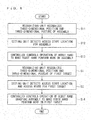
- Fig. 3 is a flowchart explaining the operation of the working unit control device 100 of the preferred embodiment. More specifically, Fig. 3 explains grasp of the first target 20 with the robot hand 5R (to be specific, work of fitting the robot hand 5R as a second target to the first target 20).
- the recognizing unit 2 of the working unit control device 100 recognizes the three-dimensional position and the three-dimensional posture of the first target 20 (step S1) :
- the recognizing unit 2 acquires a parallax image of the first target 20 by using the camera 50 attached to the robot hand 5R, and generates a group of measurement points each containing three-dimensional position information.
- ICP active closest point
- the group of model points mentioned here is a point group prepared in advance for a target and composed of points each containing three-dimensional position information.
- the ICP matching is a way of matching performed by using the ICP algorithm between data about a point group composed of points each containing three-dimensional position information and data about a point group composed of points each containing three-dimensional position information.
- the setting unit 3 of the working unit control device 100 sets an access start location and an access route for the first target 20 (step S2).
- the access start location for the first target 20 indicates the three-dimensional position and the three-dimensional posture of the second target (here, robot hand) in which the second target starts to move to be fitted to the first target 20.
- the access start location is set for the first target 20 according to the type of the second target, for example. Thus, a plurality of access start locations may be set for one first target 20.
- the number of access start locations to be set for each part type is not limited to one.
- the access route for the first target 20 is a route of movement along which the second target to be fitted to the first target 20 starts to move from the access start location to finally reach a three-dimensional position and a three-dimensional posture (final destination position and final destination posture) in which the second target is fitted to the first target 20.
- the access route is also set for the first target 20 according to the type of the second target, for example.
- a plurality of access routes may be set for one first target 20.
- the number of access routes to be set for each part type is not limited to one, but an access route to be used capable of achieving high fitting accuracy easily can be selected from a plurality of access routes, for example.
- a three-dimensional posture the second target to be fitted to the first target 20 should keep is set in the access start location.
- a three-dimensional posture to be set with respect to the access route may be given a certain degree of freedom depending on the geometric shape of the second target.
- only a three-dimensional posture in a direction along the access route may be set, while the second target may be in any three-dimensional posture in other directions.
- the second target is a member of a shape (such as a column) concentric with an axis along the access route, the second target may be allowed to rotate freely about the axis along the access route.
- the second target and the first target 20 do not contact each other on the access route until the second target reaches the final destination position and the final destination posture.
- the access route connecting each part of the second target to be fitted to the first target 20 and a corresponding part of the first target 20 to be fitted there are no other parts of the first target 20 and no other parts of the second target to be fitted to these parts of the first target 20.
- the access route may be a linear or spiral route, for example.
- Figs. 4 to 6 each show an exemplary access start location 30 and an exemplary access route 31 for the first target 20.
- Fig. 4 shows the robot hand 5R as the second target placed in a default position and the first target 20.
- Fig. 5 shows the robot hand 5R placed in the access start location 30 and the first target 20.
- Fig. 6 shows a condition where the robot hand 5R grasps the first target 20.
- the access start location 30 is set in the direction of a Z-axis (direction normal to the first target 20) of a coordinate system on the first target 20 to be in a three-dimensional position spaced a certain distance from a surface of the first target 20.
- a three-dimensional posture the robot hand 5R should keep is set with respect to the access route 31.
- the robot hand 5R is placed to comply with the three-dimensional position and the three-dimensional posture set in the access start location 30. More specifically, the robot hand 5R is placed in the three-dimensional position in the access start location 30 such that the direction of a Z-axis of a coordinate system on the robot hand 5R (direction normal to a grasping surface A) agrees with the direction of the Z axis of the coordinate system on the first target 20 set in the access start location 30.
- the robot hand 5R is placed in the aforementioned three-dimensional position and the three-dimensional posture.
- the access route 31 connecting each finger 25 of the robot hand 5R and a corresponding part 20A of the first target 20 to be grasped, there are no other parts of the first target 20 and no other parts of the robot hand 5R.
- the robot hand 5R and the first target 20 do not contact each other until the robot hand 5R reaches the final destination position and the final destination posture in which the robot hand 5R grasps the first target 20.
- the access route 31 is not necessarily a route along an axis of the coordinate system on the first target 20, but it may also be a route set in directions containing a plurality of axial components on the first target 20, for example.
- the access start location 30 is set in a three-dimensional position, and a distance along the access route 31 of this three-dimensional position from the first target 20 can be selected freely according to the geometrical shape or the size of the second target. Meanwhile, such a distance should be determined to satisfy at least the condition of preventing contact between the second target (robot hand 5R) placed in the access start location 30 and the first target 20. Further, regarding setting of the access route 31 and the access start location 30 for a second target having the same shape of a part to be fitted while only differing in a length in the direction of the access route 31, the same access route 31 may be used while only the access start location 30 is changed for this second target. By doing so, work can be performed efficiently.
- the controller 4 of the working unit control device 100 controls the operation of the robot hand 5R as the working unit 5 to make the robot hand 5R perform work on the first target 20 (step S3), as described below by referring to Figs. 4 to 6 .
- the controller 4 moves the robot hand 5R placed in the default position (see Fig. 4 ) to the three-dimensional position in the access start location 30 (see Fig. 5 ).
- the robot hand 5R may be placed in the three-dimensional position based on a TCP (tool-center point).
- the TCP mentioned here is a three-dimertsional position in a robot coordinate system defined for each robot hand and which functions as a reference point for the root hand 5R to grasp a part.
- a three-dimensional position a TCP 32 should reach is a reference three-dimensional position of the robot hand 5R while the robot hand 5R grasps the first target 20.
- the TCP 32 is defined on a surface of the first target 20, for example.
- the three-dimensional posture of the robot hand 5R is changed based on the setting of a three-dimensional posture in the access start location 30. At this time, the three-dimensional posture and the three-dimensional position of the robot hand 5R may be adjusted simultaneously.
- the controller 4 guides the robot hand 5R along the access route 31 to make the robot hand 5R access the first target 20.
- the controller 4 moves the robot hand 5R such that the robot hand 5R keeps its three-dimensional posture set in the access start location 30 with respect to the access route 31.
- the three-dimensional posture of the robot hand 5R is set such that each finger 25 of the robot hand 5R agrees with a corresponding part 20A of the first target 20 to be grasped.
- each finger 25 of the robot hand 5R reaches the corresponding part 20A of the first target 20 to be grasped (see Fig. 6 ).
- the robot hand 5R is moved straight from the default position (see Fig. 4 ) to make the robot hand 5R grasp the first target 20 without consideration for the access start location 30, the robot hand 5R and the first target 20 contact each other before being fitted together appropriately, as shown in Fig. 7 .
- the aforementioned movement of the robot hand 5R makes it possible to prevent contact of the robot hand 5R with the first target 20 on the route of movement extending until the robot hand 5R grasps the first target 20.
- Figs. 8 to 11 the robot hand 5R grasps an assembly 21, and the assembly 21 is assembled to a first target 40 (to be specific, the assembly 21 is fitted as a second target to the first target 40).
- Fig. 8 is a flowchart explaining the operation of a working unit control device of the first modification.
- Figs. 9 to 11 each show an exemplary access start location and an exemplary access route for the first target 40.
- the recognizing unit 2 of the working unit control device 100 recognizes the three-dimensional position and the three-dimensional posture of the assembly 21 (step S11).
- the recognizing unit 2 acquires a parallax image of the assembly 21 by using the camera 50 attached to the robot hand 5R, and generates a group of measurement points each containing three-dimensional position information. Then, ICP matching is perforined between the group of measurement points and a group of model points. As a result of the ICP matching, the three-dimensional position of the group of measurement points and that of the group of model points relative to each other are recognized. Then, based on the three-dimcnsional position and the three-dimensional posture of the group of model points in a robot coordinate system, the three-dimensional position and the three-dimensional posture of the group of measurement points (assembly 21) can be recognized in the robot coordinate system.
- the setting unit 3 of the working unit control device 100 sets an access start location and an access route for the assembly 21 (step S12).
- the access start location for the assembly 21 indicates the three-dimensional position and the three-dimensional posture of a different part (here, robot hand) in which the different part starts to move to be fitted to the assembly 21.
- the access start location is set for the assembly 21 according to the type of a part to be fitted, for example.
- controller 4 of the working unit control device 100 controls the operation of the robot hand 5R as the working unit 5 to make the robot hand 5R perform work on the assembly 21 (step S13).
- the controller 4 moves the robot hand 5R along the access route to make the robot hand 5R grasp the assembly 21.
- the recognizing unit 2 of the working unit control device 100 recognizes the three-dimensional position and the three-dimensional posture of the first target 40 (step S1).
- the setting unit 3 of the working unit control device 100 sets an access start location and an access route for the first target 40 (step S2).
- the access start location and the access route set at this time are those for the first target 40 relating to the assembly 21: Meanwhile, if an access start location and an access route relating to the assembly 21 can be set that allow for a condition where the robot hand 5R grasps a certain position of the assembly 21, it is desirable that such access start location and such access route be selected.
- the controller 4 of the working unit control device 100 controls the operation of the robot hand 5R grasping the assembly 21 to make the robot hand 5R perform work on the first target 40 (step S14), as described below by referring to Figs. 9 to 11 .
- the controller 4 moves the assembly 21 grasped with the robot hand 5R (see Fig. 9 ) to the three-dimensional position in the access start location 30 (see Fig. 10 ). At this time, the controller 4 exerts control such that the TCP 32 of the robot hand 5R is moved to a three-dimensional position farther from the first target 40 than the access start location 30 for the first target 40.
- the controller 4 controls the robot hand 5R so as to guide the assembly 21 along the access route 31, thereby making the assembly 21 access the first target 40.
- the three-dimensional posture of the assembly 21 is set such that each assembly part 26 of the assembly 21 agrees with a corresponding part 40A of the first target 40 to receive the assembly part 26.
- each assembly part 26 of the assembly 21 reaches the corresponding part 40A of the first target 40 to receive the assembly part 26 (see Fig. 11 ).
- a parallax image of a higher resolution can be obtained by moving the camera 50 to be sufficiently close to the first target.
- the recognizing unit 2 can recognize the three-dimensional position and the three-dimensional posture of the first target with a higher degree of accuracy if a parallax image of a higher resolution can be obtained.
- the camera 50 capture an image of the first target from a direction that minimizes overlap of surfaces of the first target.
- the access start location described in the preferred embodiment can be a three-dimensional position as close as possible to the first target in a range that prevents contact between the second and first targets.
- work can be preformed more accurately by capturing an image of the first target again by using the camera 50 in the access start location, and by recognizing the three-dimensional position and the three-dimensional posture of the first target again based on a resultant parallax image. If the access start location and the access route are changed in response to the second recognition of the three-dimensional position and the three-dimensional posture of the first target, the recognized three-dimensional position and the recognized three-dimensional posture of a part such as an assembly may be updated according to the change.
- the access route of the preferred embodiment connecting each part of the second target to be fitted to the first target and a corresponding part of the first target to be fitted, there are no other parts of the first target and no other parts of the second target to be fitted to these parts of the first target.
- the access route is set as a linear route, particularly, surfaces of the first target do not overlap each other as viewed from the camera 50 arranged on the access route. This does not generate a surface in the first target to become a rear surface that cannot be subjected to recognition of a three-dimensional position and a three-dimensional posture.
- the camera 50 on the access route and making the camera 50 capture an image of the first target again, the three-dimensional position and the three-dimensional posture of the first target can be recognized more accurately.
- the working unit control device includes: the recognizing unit 2 that recognizes the three-dimensional position and the three-dimensional posture of the first target; the setting unit 3 that sets an access start location and an access route based on the recognized three-dimensional position and the recognized three-dimensional posture of the first target, the access start location indicating the three-dimensional position and the three-dimensional posture of the second target (assembly 21 or robot hand 5R itself) in which the second target starts to access for fitting, the access route indicating a route of movement of the second target; and the controller 4 that controls the working unit 5 to fit the second target to the first target.
- This structure allows the second target to move along the access route being a route of movement leading from the access start location to the first target and on which the second and first targets do not contact each other in the middle of the route of movement.
- the second and first targets can be fitted appropriately by controlling the working unit 5 (robot hand 5R) while contact between the second and first targets is prevented.
- At least the three-dimensional position of the second target and the three-dimensional posture of the second target in a direction along the access route are set in the access start location.
- This structure provides a certain degree of freedom to the three-dimensional posture of the second target, depending on the shape of the second target.
- the second target can be arranged according to setting of the access start location easily.
- the image capturing unit 6 captures an image of the first target again in the access start location, and the recognizing unit 2 updates the recognized three-dimensional position and the recognized three-dimensional posture of the first target based on the image of the first target captured by the image capturing unit 6 in the access start location.
- This structure allows the camera 50 being the image capturing unit 6 to capture an image of the first target in a position close to the first target, thereby making it possible to obtain a parallax image of a higher resolution. Additionally, surfaces of the first target do not overlap each other as viewed from the camera 50 being the image capturing unit 6, making it possible to obtain a more precise parallax image of the surfaces of the first target. As a result, the recognized three-dimensional position and the recognized three-dimensional posture of the first target can be updated to a more accurate three-dimensional position and a more accurate three-dimensional posture.
- a working unit control method includes the steps of: capturing an image of the first target again in the access start location; updating the recognized three-dimensional position and the recognized three-dimensional posture of the first target based on the image of the first target captured in the access start location; and fitting the second target to the first target by controlling the working unit 5 based on the recognized three-dimensional position and the recognized three-dimensional posture of the first target thereby updated.
- the image capturing unit 6 (camera 50) is moved to the access start location based on the three-dimensional position and the three-dimensional posture of the first target recognized once, and captures an image of the first target again in the access start location.
- a more accurate three-dimensional position and a more accurate three-dimensional posture of the first target can be recognized.
- the working unit 5 can be controlled based on a more accurate access start location and a more accurate access route.
- any component of the preferred embodiment can be modified or omitted without departing from the scope of the invention.
Landscapes
- Engineering & Computer Science (AREA)
- Robotics (AREA)
- Mechanical Engineering (AREA)
- Health & Medical Sciences (AREA)
- General Health & Medical Sciences (AREA)
- Orthopedic Medicine & Surgery (AREA)
- General Engineering & Computer Science (AREA)
- Physics & Mathematics (AREA)
- General Physics & Mathematics (AREA)
- Automation & Control Theory (AREA)
- Manipulator (AREA)
Applications Claiming Priority (1)
| Application Number | Priority Date | Filing Date | Title |
|---|---|---|---|
| JP2012215514A JP2014069251A (ja) | 2012-09-28 | 2012-09-28 | 作業部制御装置、作業ロボット、作業部制御方法、および作業部制御プログラム |
Publications (2)
| Publication Number | Publication Date |
|---|---|
| EP2712715A2 true EP2712715A2 (de) | 2014-04-02 |
| EP2712715A3 EP2712715A3 (de) | 2016-01-13 |
Family
ID=48190082
Family Applications (1)
| Application Number | Title | Priority Date | Filing Date |
|---|---|---|---|
| EP13162142.7A Withdrawn EP2712715A3 (de) | 2012-09-28 | 2013-04-03 | Bearbeitungseinheits-Steuerungsvorrichtung, Bearbeitungsroboter, Bearbeitungseinheits-Steuerverfahren, und Bearbeitungseinheits-Steuerprogramm |
Country Status (3)
| Country | Link |
|---|---|
| US (1) | US20140094951A1 (de) |
| EP (1) | EP2712715A3 (de) |
| JP (1) | JP2014069251A (de) |
Cited By (2)
| Publication number | Priority date | Publication date | Assignee | Title |
|---|---|---|---|---|
| CN105835060A (zh) * | 2016-05-23 | 2016-08-10 | 先驱智能机械(深圳)有限公司 | 控制方法、控制装置及机械手系统 |
| WO2018160163A1 (en) * | 2017-02-28 | 2018-09-07 | Siemens Product Lifecycle Management Software Inc. | System and method for determining grasping positions for two-handed grasps of industrial objects |
Families Citing this family (4)
| Publication number | Priority date | Publication date | Assignee | Title |
|---|---|---|---|---|
| US9778650B2 (en) * | 2013-12-11 | 2017-10-03 | Honda Motor Co., Ltd. | Apparatus, system and method for kitting and automation assembly |
| JP6459227B2 (ja) * | 2014-06-02 | 2019-01-30 | セイコーエプソン株式会社 | ロボットシステム |
| KR101825094B1 (ko) * | 2016-06-08 | 2018-02-02 | 한양대학교 산학협력단 | 파지 동작 계획 방법 및 장치 |
| TWI696529B (zh) * | 2018-11-30 | 2020-06-21 | 財團法人金屬工業研究發展中心 | 自動定位方法以及自動控制裝置 |
Citations (1)
| Publication number | Priority date | Publication date | Assignee | Title |
|---|---|---|---|---|
| JP2011112400A (ja) | 2009-11-24 | 2011-06-09 | Omron Corp | 3次元視覚センサ |
Family Cites Families (15)
| Publication number | Priority date | Publication date | Assignee | Title |
|---|---|---|---|---|
| JP3064348B2 (ja) * | 1990-08-02 | 2000-07-12 | 豊田工機株式会社 | ロボット制御装置 |
| JP3702257B2 (ja) * | 2002-08-23 | 2005-10-05 | ファナック株式会社 | ロボットハンドリング装置 |
| AU2003278994A1 (en) * | 2002-09-26 | 2004-04-19 | Barrett Technology, Inc. | Intelligent, self-contained robotic hand |
| DE10345743A1 (de) * | 2003-10-01 | 2005-05-04 | Kuka Roboter Gmbh | Verfahren und Vorrichtung zum Bestimmen von Position und Orientierung einer Bildempfangseinrichtung |
| US7783383B2 (en) * | 2004-12-22 | 2010-08-24 | Intelligent Hospital Systems Ltd. | Automated pharmacy admixture system (APAS) |
| WO2007149183A2 (en) * | 2006-05-25 | 2007-12-27 | Braintech Canada, Inc. | System and method of robotically engaging an object |
| JP5448326B2 (ja) * | 2007-10-29 | 2014-03-19 | キヤノン株式会社 | 把持装置および把持装置制御方法 |
| JP5528095B2 (ja) * | 2009-12-22 | 2014-06-25 | キヤノン株式会社 | ロボットシステム、その制御装置及び方法 |
| US9124873B2 (en) * | 2010-12-08 | 2015-09-01 | Cognex Corporation | System and method for finding correspondence between cameras in a three-dimensional vision system |
| JP5835926B2 (ja) * | 2011-04-11 | 2015-12-24 | キヤノン株式会社 | 情報処理装置、情報処理装置の制御方法、およびプログラム |
| JP2013184257A (ja) * | 2012-03-08 | 2013-09-19 | Sony Corp | ロボット装置及びロボット装置の制御方法、並びにコンピューター・プログラム |
| US9233470B1 (en) * | 2013-03-15 | 2016-01-12 | Industrial Perception, Inc. | Determining a virtual representation of an environment by projecting texture patterns |
| US9283674B2 (en) * | 2014-01-07 | 2016-03-15 | Irobot Corporation | Remotely operating a mobile robot |
| US9272417B2 (en) * | 2014-07-16 | 2016-03-01 | Google Inc. | Real-time determination of object metrics for trajectory planning |
| US9507995B2 (en) * | 2014-08-29 | 2016-11-29 | X Development Llc | Combination of stereo and structured-light processing |
-
2012
- 2012-09-28 JP JP2012215514A patent/JP2014069251A/ja active Pending
-
2013
- 2013-04-03 EP EP13162142.7A patent/EP2712715A3/de not_active Withdrawn
- 2013-08-21 US US13/972,792 patent/US20140094951A1/en not_active Abandoned
Patent Citations (1)
| Publication number | Priority date | Publication date | Assignee | Title |
|---|---|---|---|---|
| JP2011112400A (ja) | 2009-11-24 | 2011-06-09 | Omron Corp | 3次元視覚センサ |
Cited By (3)
| Publication number | Priority date | Publication date | Assignee | Title |
|---|---|---|---|---|
| CN105835060A (zh) * | 2016-05-23 | 2016-08-10 | 先驱智能机械(深圳)有限公司 | 控制方法、控制装置及机械手系统 |
| WO2018160163A1 (en) * | 2017-02-28 | 2018-09-07 | Siemens Product Lifecycle Management Software Inc. | System and method for determining grasping positions for two-handed grasps of industrial objects |
| US11279023B2 (en) | 2017-02-28 | 2022-03-22 | Siemens Industry Software Inc. | System and method for determining grasping positions for two-handed grasps of industrial objects |
Also Published As
| Publication number | Publication date |
|---|---|
| EP2712715A3 (de) | 2016-01-13 |
| US20140094951A1 (en) | 2014-04-03 |
| JP2014069251A (ja) | 2014-04-21 |
Similar Documents
| Publication | Publication Date | Title |
|---|---|---|
| EP2931485B1 (de) | Freihändiges roboterpfad-training | |
| EP2712715A2 (de) | Bearbeitungseinheits-Steuerungsvorrichtung, Bearbeitungsroboter, Bearbeitungseinheits-Steuerverfahren, und Bearbeitungseinheits-Steuerprogramm | |
| US11833696B2 (en) | Vision-based sensor system and control method for robot arms | |
| EP2460628A2 (de) | Robotervorrichtung und Greifverfahren zur Verwendung in einer Robotervorrichtung | |
| CN107717981B (zh) | 机械手臂的控制装置及其教导系统与方法 | |
| CN109313417B (zh) | 帮助机器人定位 | |
| EP3221095B1 (de) | Roboter und robotersystem | |
| US20190036337A1 (en) | System for robotic 3d printing | |
| US9387589B2 (en) | Visual debugging of robotic tasks | |
| US8155787B2 (en) | Intelligent interface device for grasping of an object by a manipulating robot and method of implementing this device | |
| US9457475B2 (en) | Robotic placement and manipulation with enhanced accuracy | |
| CN104942803B (zh) | 机器人控制装置、机器人、机器人系统、示教方法及程序 | |
| JP7632469B2 (ja) | ロボット制御装置、およびロボット制御方法、並びにプログラム | |
| US20160136807A1 (en) | Determination of Object-Related Gripping Regions Using a Robot | |
| EP2591888A1 (de) | Montagevorrichtung und -verfahren, und Montagebetriebsprogramm | |
| JP2017170599A (ja) | ロボットを用いた位置決め装置 | |
| JP2019107704A (ja) | ロボットシステム及びロボット制御方法 | |
| JP2014161950A (ja) | ロボットシステム、ロボット制御方法、ロボット較正方法 | |
| JP2014151377A (ja) | ロボット制御方法、ロボット制御装置、ロボットシステム、ロボット及びプログラム | |
| JP2015074061A (ja) | ロボット制御装置、ロボットシステム、ロボット、ロボット制御方法及びロボット制御プログラム | |
| CN121464021A (zh) | 用于补偿自主充电设备的操纵器的多个工作姿态中的偏差的方法和系统 | |
| CN107735226B (zh) | 利用机器人驶过预设的轨迹 | |
| CN117621040A (zh) | 机器人控制系统、机器人控制方法以及计算机可读取记录介质 | |
| JP2015174206A (ja) | ロボット制御装置、ロボットシステム、ロボット、ロボット制御方法及びロボット制御プログラム | |
| JP2016203282A (ja) | エンドエフェクタの姿勢変更機構を備えたロボット |
Legal Events
| Date | Code | Title | Description |
|---|---|---|---|
| PUAI | Public reference made under article 153(3) epc to a published international application that has entered the european phase |
Free format text: ORIGINAL CODE: 0009012 |
|
| AK | Designated contracting states |
Kind code of ref document: A2 Designated state(s): AL AT BE BG CH CY CZ DE DK EE ES FI FR GB GR HR HU IE IS IT LI LT LU LV MC MK MT NL NO PL PT RO RS SE SI SK SM TR |
|
| AX | Request for extension of the european patent |
Extension state: BA ME |
|
| RAP1 | Party data changed (applicant data changed or rights of an application transferred) |
Owner name: SCREEN HOLDINGS CO., LTD. |
|
| RIN1 | Information on inventor provided before grant (corrected) |
Inventor name: SASA, YASUSHI |
|
| PUAL | Search report despatched |
Free format text: ORIGINAL CODE: 0009013 |
|
| AK | Designated contracting states |
Kind code of ref document: A3 Designated state(s): AL AT BE BG CH CY CZ DE DK EE ES FI FR GB GR HR HU IE IS IT LI LT LU LV MC MK MT NL NO PL PT RO RS SE SI SK SM TR |
|
| AX | Request for extension of the european patent |
Extension state: BA ME |
|
| RIC1 | Information provided on ipc code assigned before grant |
Ipc: B25J 9/16 20060101AFI20151209BHEP |
|
| STAA | Information on the status of an ep patent application or granted ep patent |
Free format text: STATUS: THE APPLICATION IS DEEMED TO BE WITHDRAWN |
|
| 18D | Application deemed to be withdrawn |
Effective date: 20160714 |