EP2712962A2 - Vorrichtung zum Verbinden zweier mobiler Schutzwandelemente - Google Patents
Vorrichtung zum Verbinden zweier mobiler Schutzwandelemente Download PDFInfo
- Publication number
- EP2712962A2 EP2712962A2 EP13177998.5A EP13177998A EP2712962A2 EP 2712962 A2 EP2712962 A2 EP 2712962A2 EP 13177998 A EP13177998 A EP 13177998A EP 2712962 A2 EP2712962 A2 EP 2712962A2
- Authority
- EP
- European Patent Office
- Prior art keywords
- protective wall
- mobile protective
- wall element
- rail
- connecting means
- Prior art date
- Legal status (The legal status is an assumption and is not a legal conclusion. Google has not performed a legal analysis and makes no representation as to the accuracy of the status listed.)
- Granted
Links
Images







Classifications
-
- E—FIXED CONSTRUCTIONS
- E01—CONSTRUCTION OF ROADS, RAILWAYS, OR BRIDGES
- E01F—ADDITIONAL WORK, SUCH AS EQUIPPING ROADS OR THE CONSTRUCTION OF PLATFORMS, HELICOPTER LANDING STAGES, SIGNS, SNOW FENCES, OR THE LIKE
- E01F15/00—Safety arrangements for slowing, redirecting or stopping errant vehicles, e.g. guard posts or bollards; Arrangements for reducing damage to roadside structures due to vehicular impact
- E01F15/02—Continuous barriers extending along roads or between traffic lanes
- E01F15/08—Continuous barriers extending along roads or between traffic lanes essentially made of walls or wall-like elements ; Cable-linked blocks
- E01F15/088—Details of element connection
-
- E—FIXED CONSTRUCTIONS
- E01—CONSTRUCTION OF ROADS, RAILWAYS, OR BRIDGES
- E01F—ADDITIONAL WORK, SUCH AS EQUIPPING ROADS OR THE CONSTRUCTION OF PLATFORMS, HELICOPTER LANDING STAGES, SIGNS, SNOW FENCES, OR THE LIKE
- E01F15/00—Safety arrangements for slowing, redirecting or stopping errant vehicles, e.g. guard posts or bollards; Arrangements for reducing damage to roadside structures due to vehicular impact
- E01F15/02—Continuous barriers extending along roads or between traffic lanes
- E01F15/08—Continuous barriers extending along roads or between traffic lanes essentially made of walls or wall-like elements ; Cable-linked blocks
- E01F15/081—Continuous barriers extending along roads or between traffic lanes essentially made of walls or wall-like elements ; Cable-linked blocks characterised by the use of a specific material
- E01F15/083—Continuous barriers extending along roads or between traffic lanes essentially made of walls or wall-like elements ; Cable-linked blocks characterised by the use of a specific material using concrete
-
- E—FIXED CONSTRUCTIONS
- E01—CONSTRUCTION OF ROADS, RAILWAYS, OR BRIDGES
- E01F—ADDITIONAL WORK, SUCH AS EQUIPPING ROADS OR THE CONSTRUCTION OF PLATFORMS, HELICOPTER LANDING STAGES, SIGNS, SNOW FENCES, OR THE LIKE
- E01F15/00—Safety arrangements for slowing, redirecting or stopping errant vehicles, e.g. guard posts or bollards; Arrangements for reducing damage to roadside structures due to vehicular impact
- E01F15/02—Continuous barriers extending along roads or between traffic lanes
- E01F15/08—Continuous barriers extending along roads or between traffic lanes essentially made of walls or wall-like elements ; Cable-linked blocks
- E01F15/081—Continuous barriers extending along roads or between traffic lanes essentially made of walls or wall-like elements ; Cable-linked blocks characterised by the use of a specific material
- E01F15/086—Continuous barriers extending along roads or between traffic lanes essentially made of walls or wall-like elements ; Cable-linked blocks characterised by the use of a specific material using plastic, rubber or synthetic materials
Definitions
- the invention relates to a device for connecting a first mobile protective wall element to a second mobile protective wall element according to the preamble of claim 1.
- Protective wall constructions made of a plurality of individual protective wall elements are known to the person skilled in the art and are preferably used to secure traffic routes, in particular for temporary or permanent stationary securing in the area of construction sites, workplaces and roads or the like. They are also used to protect against or against off-road vehicles and to protect persons or special facilities adjacent to a road.
- the publication DE 20 2011 104 387 U1 discloses a generic device for connecting mobile protective wall elements.
- This device is T-shaped, wherein a horizontal component extends below the protective wall elements and a vertical component is oriented at right angles to the horizontal component. Both components of the device are firmly connected.
- This device has the disadvantage that it is relatively heavy, whereby the assembly or disassembly of a mobile protective wall is very force or personnel-intensive and therefore expensive.
- the device according to the invention for connecting a first mobile protective wall element to a second mobile protective wall element comprises a first connecting means, which is preferably designed as a longitudinally extending rail or as a longitudinally extending rail element, and a second connecting means arranged at least two at a predetermined distance from each other having parallel wall parts.
- first connecting means and the second connecting means By means of the first connecting means and the second connecting means, the first mobile protective wall element and the second mobile protective wall element to each other in a predetermined orientation fixing active compound can be generated, wherein the first connecting means at least partially below the first mobile protective wall element and at least partially below the second mobile protective wall element in one first coupling region for forming a connection between the first mobile protective wall element and the second mobile protective wall element can be arranged.
- the second connection means can be arranged in a second coupling region extending orthogonally to the longitudinal direction of the first connection means between the first mobile protective wall element and the second mobile protective wall element.
- the first connection means and the second connection means are designed as separate components and thus can be arranged at a distance from one another.
- first connecting means and the second connecting means in each case for a positive engagement with the first mobile protective wall element and the second mobile protective wall element defined surface areas.
- This embodiment is advantageous because it is ensured by the defined surface areas that when entering a vehicle in one or the first mobile protective wall element, the forces introduced into the one protective wall element forces are transmitted to the further or second mobile protective wall element.
- support elements are arranged on the rail in the width direction on both sides, which are formed for lying flat on a substrate.
- This embodiment is advantageous because the rail can rest extremely stable and flat on the ground by the support elements, in particular to compensate for unevenness of the ground.
- an upper-side surface of the rail element is at least partially negative or complementary to the underside surface of the mobile protective wall elements.
- This embodiment variant is advantageous because a positive connection between the mobile protective wall element and the first connection means is formed by the complementary design, which further improves the connection effect.
- the upper-side surface of the support elements can be brought into surface contact, at least in sections, with the underside surface of the first mobile protective wall element and the second mobile protective wall element the rail element has a lower surface which preferably extends in a first plane, while the underside surface of the support elements which can be brought into contact with the substrate extends in a second plane, wherein the first plane is formed in the height direction above the second plane.
- the rail element is at least partially formed by extending in the height direction Wandungsanteile, which can be brought into contact with the mobile protective wall elements in the first coupling region, wherein the wall portions preferably consist of a first wall portion and a second wall portion, wherein the first wall portion of the rail element or the rail and the second wall portion of the rail for forming an upwardly open profile exclusively on the underside by a further wall portion of the rail are interconnected.
- This embodiment is advantageous since a rail with an open profile can receive the mobile protective wall elements in a form-fitting manner in a simple manner. This results in an easy to disassemble and to mount arrangement.
- the first wall portion of the rail and the second wall portion of the rail for forming a closed profile on the underside and top side, in particular by means of further Wandungsanteile, connected to each other, wherein the closed profile is preferably a hollow profile.
- An advantage of this embodiment is that a hollow profile allows a very rigid rail shape, whereby the maximum load capacity is increased compared to an open profile.
- the rail has a multiplicity of connecting points, in particular holes, wherein at least one connecting point can be assigned to the first mobile protective wall element and at least one further connecting point can be assigned to the second mobile protective wall element.
- the rail or the rail element in this way can optionally also be connected to the first and / or the second mobile protective wall element by means of a further, preferably releasable connection, in particular a screw connection.
- the connecting means can be arranged at a predetermined distance to the rail element, wherein the connecting means is preferably positively and / or materially connectable with at least one mobile protective wall element, preferably by means of a welded connection.
- connection means can be arranged in this way in a manner that is suitable for loading and optimized with respect to simple assembly / disassembly.
- the two wall portions of the connecting means in the second coupling region are weldable to at least one mobile protective wall element.
- This embodiment is advantageous because the connecting means can be arranged captive on the first or second mobile protective wall element in this way.
- This embodiment variant is advantageous in that the pressure-applying means is defined and can be attached in a protected manner, thereby preventing unwanted premature failure of the pressing means, e.g. as a result of incorrect assembly or environmental influences, is prevented.
- This protective wall comprises at least a first mobile protective wall element and a second mobile protective wall element.
- first mobile protective wall element and the second mobile protective wall element connected to each other by means of a device according to the invention, wherein the rail element in a first coupling region, preferably underside positively, with the first mobile protective wall element and the second mobile protective wall element in contact, and wherein the connecting means in a second coupling region with the first mobile Protective wall element and the second mobile protective wall element is in contact, preferably frontally positively, and wherein the first contact region extends in a first direction, which is aligned orthogonally to the extension direction of the second contact region.
- the rail element and the connecting means are formed as separate components and spaced from each other.
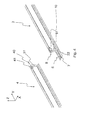
- Fig. 1 is the device 1, which consists of a first connecting means or rail element 6 and a second connecting means 8, shown.
- the device 1 is connected to a first mobile protective wall element 2.
- the first connection means 6 has a rail-like middle region 7 and two support elements 16 arranged laterally thereon.
- the support elements 16 extend substantially in the X / Y plane and are spaced apart in the X direction by the rail-like central region 7.
- the X direction preferably corresponds to the depth direction
- the Y direction preferably corresponds to the longitudinal direction
- the Z direction preferably corresponds to the height direction.
- the reference numeral 18 denotes the upper-side surface of the first connecting means 6, which at least in sections, in particular in the region of the support elements 16, with the lower side of the protective wall element 2 can be brought into contact, which has a lower side (continuous) recess for this purpose.
- the second connecting means 8 is arranged at a distance from the first connecting means 6 on the mobile protective wall element 2 in the Z direction. It is in the elements 6, 8 and completely separate, separate components of the device 1.
- the second connecting means 8 is arranged frontally of the mobile protective wall element 2 and does not extend beyond this in the Z direction.
- the first connection means 6 extends many times further in the X and Y directions than the second connection means 8. According to the in Fig. 2 As shown, the underside surface 20 of the mobile protective wall element 2 can be seen, with which the in Fig. 1 shown top surface 18 of the first connecting means 6 is at least partially brought into contact. Furthermore, the underside surface of the first connecting means 6 is designated by the reference numeral 24.
- the underside surface 24 of the first connecting means 6 is preferably on a solid ground, such as a road, erectable.
- Reference numeral 19 denotes the underside surface of the support elements 16, and reference numeral 24 denotes a bottom surface of the rail 7.
- the latter surface 24 need not be continuous, but may - as shown - consist of a plurality of spaced-apart elements (transverse webs).
- FIG. 3 illustrated exploded view shows a mobile protective wall element 2, the first connecting means 6 and a special embodiment of the second connecting means 8. Furthermore, this representation can be seen from a bracing or pressing means 40, which is preferably designed as a screw.
- the pressing means 40 is preferably used for clamping two mobile protective wall elements 2, 4 in the direction of their longitudinal extent (see. FIGS. 4 et seq.). In the case of the retraction of a vehicle in the mobile protective wall, the pressing means 40 thus serves as a transmission element, by which the forces occurring on another mobile protective wall element 2, 4 are transferable.
- Reference numerals 12 and 14 denote the first and the second coupling region, respectively.
- the first coupling region 12 serves to connect a lower side frame part 13 of the protective wall element 2, which extends substantially in the wall longitudinal direction, to the first connection means 6.
- the second coupling region 14 serves to connect a substantially vertically extending end frame part 15 to the second connection means 8
- Frame parts 13, 15 are preferably formed in metal (steel).
- the frame part 15 has in this embodiment a hole 41 for passing the contact pressure means 40.
- the hole 41 is arranged such that the pressing means 40 also extends in an installed state with its longitudinal axis in the Y direction and is substantially adjacent to a corresponding hole of another mobile protective wall element through which the pressing means 40 also extends.
- the second connecting means 8 is formed according to this embodiment as a tubular element with a rectangular, in particular square, cross-section.
- the second connecting means 8 in this case has the pipe element forming wall portions 10, 11, wherein two wall portions 10 are arranged spaced apart by means of two wall portions 11.
- the wall parts 10 are each for abutment against a first frame wall 50 and a second frame wall 51 of the frame part 15.
- the two frame walls 50, 51 are aligned parallel or substantially parallel to each other. Therefore, the wall parts 10 of the second connecting means 8 are also aligned parallel or substantially parallel to each other.
- the distance between the wall portions 10 is determined by the wall portions 11 and corresponds to the distance between the opposing surfaces of the first frame wall 50 and the second frame wall 51st
- the second connecting means 8 in the wall parts 11 introduced openings or holes 42, which are connected to each other by means of a tubular means 44.
- the tubular means 44 is designed as a round tubular element, through which the pressing means 40 can extend therethrough or in which the pressing means 40 can be accommodated.
- a first mobile protective wall element 2 and a second mobile protective wall element 4 are shown.
- the first mobile protective wall element 2 is already at least partially coupled to the first and second connecting means 6, 8.
- both connecting means 6, 8 are superimposed and / or enclosed substantially or exactly half of their extent in the longitudinal direction Y by the first mobile protective wall element 2.
- the wall part 10 of the second connecting means 8 is only partially, in particular substantially or exactly half, superimposed by the second frame wall 51 in the Y direction.
- the remaining, not superimposed portion of the wall 10 is completely or substantially completely overlaid by the second frame 51 of the second mobile protective wall element 4.
- the second mobile protective wall element 4 also has a hole 41, through which the pressing means 40 can be guided at least partially.
- Fig. 5 a state is shown in which the first mobile protective wall element 2 and the second mobile protective wall element 4 are connected to each other by means of the first and second connecting means 6, 8 such that an offset of the protective wall elements 2, 4 to each other at least in the X direction and preferably also in Y- and / or Z-direction is excluded or prevented.
- the mobile protective wall elements 2, 4 have at their lower in the longitudinal direction Y extending frame members 13 arranged lateral support elements 17, which are designed to be brought into contact with a first connection means 6 and / or for direct contact with a substrate.
- the wall elements 2, 4 are secured in this way against tipping to the side.
- the mobile protective wall elements 2, 4 are also bounded by metallic frame parts 56.
- a packing 52 in particular of concrete, recycled plastic or a mixed / composite material is arranged between the upper frame part 56 and the lower frame part 13 of a mobile protective wall element 2, 4.
- Reflector elements 54 for reflecting light are arranged laterally in the area of the filling body 52.
- FIG. 6 is indicated by the area marked with the letter A, that in the FIGS. 7a and 7b Assigned arrangements are assigned to the designated location.
- Fig. 7a is a side view of a mobile protective wall element 14 with disposed thereon first and second connecting means 6, 8 reproduced.
- the first, at least partially rail-like extending connecting means 6 acts in a coupling region 12 with the second mobile protective wall element 4 surface contacting together.
- the reference numeral 53 denotes a mounting region which defines a recess, by means of which the accessibility to the pressure means 40 is made possible.
- Fig. 7b is a front view of the in Fig. 7a shown arrangement reproduced.
- the supporting elements 16 of the first connecting means 6 are superimposed contacting by the supporting elements 17 of the second mobile protective wall element 4.
- the first connecting means 6 has a first vertical wall portion 26, a second vertical wall portion 28 and a further horizontal wall portion 32, which together in cross section conversely, forming a U-shaped rail-like elevation to which the second mobile protective wall element 4 has at least partially form-fittingly complementary complementary walls 58, 60, 61.
- a positive connection between the first connecting means 6 and the second mobile protective wall element 4 is therefore created by the interaction of the walls 26, 28, 32 with the opposing walls 58, 60, 61.
- the reference numerals 45 and 46 designate a first, upper opening and a second, lower opening in the tubular second connecting means 8, wherein the openings 45, 46 or their edges are connected to one another in the vertical direction by the wall parts 10, 11.
- the openings 45, 46 are each aligned in the installation or installation state in a substantially horizontal plane.
- Fig. 7c a top view of two mobile protective wall elements 2, 4 is shown, wherein the second mobile protective wall element 4 is in contact with the second connecting means 8 and is spaced from the first mobile protective wall element 2.
- the second connection means 8 is arranged on a boundary wall 62 of the frame part 15.
- the boundary wall 62 preferably forms together with the first and second frame walls 50, 51 (see also FIG FIG. 3 ) a U-profile or a double-T profile of the frame part 15.
- Fig. 8a is indicated by the area marked with the letter B, that in the FIG. 8b imaged arrangements are attributed to the designated location.
- FIG. 8b Four different embodiments are shown.
- the two embodiments arranged on the left have the second connecting means 8 already described above, which has a tubular body.
- supporting elements 17 are arranged on both sides in comparison to the lower illustration on the mobile protective wall elements 2, 4. According to the lower left illustration, however, such supporting elements 17 are not absolutely necessary.
- a support can, for example, via the first connecting means 6 (see. Fig. 1 ) respectively.
- the second connecting means 8 are formed exclusively from the mutually substantially parallel wall elements 10.
- the wall elements 10 are not directly connected to each other, but fixed non-positively, positively and / or cohesively to the frame member 15, in particular welded.
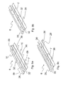
- FIG. 9a a first example of a concrete embodiment of the first connecting means 6 is shown.
- This connecting means 6 has between the support elements 16 on a rail-like portion 7, by two substantially in the Z direction extending, but slightly inclined relative to the Z direction wall portions 26, 28 and two of these wall portion 26, 28 each in an upper portion and / or in a lower portion connecting horizontal wall portions 32 is formed.
- the first and second wall portion 26, 28 are also arranged inclined to each other.
- the further wall sections 32 each extend in a horizontal plane and have connecting points 36 or holes, in particular holes of different sizes.
- FIG. 9b shown first connecting means 6 substantially corresponds to the in Fig. 9a
- Fig. 9c is still another first connecting means 6 shown.
- the rail-like portion 7 is formed only by three wall parts 26, 28, 32.
- the first and second walls 26, 28 are aligned substantially or exactly parallel to each other.
- the marked with the reference numeral 32 wall portion in this case has the direction indicated by the reference numeral 36 holes.
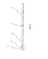
- FIG. 10a a side view of an extendable protective wall of elements 2, 4 is shown.
- the arrow C symbolizes the viewing direction for a variety of in the FIGS. 10b and 10c shown frontal views of the first connecting means. 6
- Fig. 10b is a side view of a first connecting means 6 and a plurality of different frontal views ad of the first connecting means 6 shown. Furthermore, two frontal views ef different trained frame parts 13 of the mobile protective wall elements 2, 4 are shown.
- the frontal view of the first connecting element 6 marked "a" has a rail-like portion which forms a substantially rectangular cross-section.
- the walls 26 and 28 are preferably identical. This is preferably the same for the walls 32, which are arranged at a constant distance from each other (see. FIG. 9b ).
- the walls 26 and 28 are inclined relative to one another (cf. FIG. 9a ). It can be seen that the walls 26 and 28 are arranged significantly closer to each other in an upper region than is the case in a further or lower region. As a result, the wall elements 32, which are preferably arranged parallel to one another, have different expansions in the X direction.
- a flat wall 32 is provided, through which two lower regions of an arcuate wall 27 are connected to one another.
- the walls 26 and 28 are arranged inclined relative to each other so that they touch in an upper area.
- a further wall 32 is provided, which connect the two inclined walls 26 and 28 with each other.
- the walls 26, 28 and 26, 28, 32 form a triangular or pyramidal profile.
- the two frontal views "e” and “f” of the mobile protective wall element 2, 4 differ only in that according to the variant “e” the opposing walls 60, 61 extend exclusively in the vertical direction, according to “f” still support elements 17 follow (see. FIG. 7b ).
- Fig. 10c is also a frontal view "a" of a first connecting means 6 (see. FIG. 9c ) and a frontal view "b" of a mobile protective wall element 2, 4.
- the variant shown in “a” corresponds essentially to the one in Fig. 10a with “a” marked variant, if this is performed without the upper wall 32.
- "a” is an open variant, in which the two wall parts 26 and 28 are opposite each other and define a receiving space into which a further body (the protective wall element) can be introduced.
- the body which can be introduced into the receiving space delimited by the wall parts 26 and 28 particularly preferably corresponds to the mobile protective wall element 2, 4 shown according to "b". Contrary to those shown in FIG Fig. 10b Variants shown in accordance with the in Fig. 10c variant shown a partial enclosure of the mobile protective wall element 2, 4 by the first connecting means 6th
- a first front view “a” and a second front view “f” of two first connection means 6 are shown.
- the frontal view labeled “a” is the same as in Fig. 10b with “b” designated variant.
- the frontal view labeled "f” is the same as in Fig. 10b with "a” designated variant.
- the mobile protective wall element 2, 4 forms a negative mold or complementary shape to the first connecting means 6 and is designed without lateral supporting elements 17.
- the frame part 13 of the mobile protective wall element 2, 4 is approximately omega-shaped and is in contact with the first connecting means 6 in the vertical direction only in a relatively small area, which extends substantially in the region of the lower wall 32. Due to the Omega shape, the frame part 13 forms lateral support elements, wherein it is also conceivable that these support elements 17 are arranged or arranged separately on the frame part 13.
- the frame part 13 is partially formed negative to the first connecting means 6 and is therefore in particular sections of the first connecting means 6 on.
- the frame part 13 has in this case on both sides of the rail-like element of the first connecting means 6 and arranged straight in the vertical direction extending wall portions, which are inclined downwardly to the vertical aligned Wandungsanteile.
- the inclined wall portions of the frame part 13 are in surface contact with the wall elements 26, 28 of the first connecting means 6.
- the support elements are formed such that they substantially or exactly completely overlay the support members 16 of the first connecting means 6.
- the frame member 13 is formed completely negative to the first connection means 6.
- the example “g” corresponds functionally to the example “b", wherein only the shape of the rail-like portion of the first connecting means 6 is different.
- the examples “h” and “i” have substantially or exactly negative to the first connecting means 6 formed frame parts 13.
- the frame parts 13 are likewise omega-shaped, wherein the resulting lateral support elements of the mobile protective wall elements in the example “h” only partially or in the example “i” substantially or exactly completely overlay the support elements 16 of the first connecting means 6.
- FIG. 12 different embodiments of first connecting means 6 and of frame elements 13 and mobile protective wall elements 2, 4 are shown.
- arrows are indicated, which indicate at which points the devices are in contact with each other or transmit forces to one another.
- the example “h” can be taken from a previously not yet mentioned coupling variant.
- a double “tongue and groove” connection is used.
- the mobile protective wall element 2, 4 is provided on the underside with a trapzeförmigen groove 64, and the first connecting means 6 has a complementary to the groove 64 spring 66.
Landscapes
- Engineering & Computer Science (AREA)
- Architecture (AREA)
- Civil Engineering (AREA)
- Structural Engineering (AREA)
- Refuge Islands, Traffic Blockers, Or Guard Fence (AREA)
- Details Of Indoor Wiring (AREA)
- Casings For Electric Apparatus (AREA)
- Finishing Walls (AREA)
- Fencing (AREA)
Abstract
Description
- Die Erfindung betrifft eine Vorrichtung zum Verbinden eines ersten mobilen Schutzwandelements mit einem zweiten mobilen Schutzwandelement gemäß dem Oberbegriff von Anspruch 1.
- Schutzwandkonstruktionen aus einer Vielzahl einzelner Schutzwandelemente sind dem Fachmann bekannt und dienen vorzugsweise zur Sicherung von Verkehrswegen, insbesondere zur temporären oder dauerhaft-stationären Sicherung im Bereich von Baustellen, Arbeitsstellen und Straßen oder dergleichen. Sie werden weiterhin eingesetzt zum Schutz von oder gegen von der Fahrbahn abkommende(n) Fahrzeuge(n) und zum Schutz von Personen oder besonderen Einrichtungen neben einer Straße.
- Die Druckschrift
DE 20 2011 104 387 U1 offenbart eine gattungsgemäße Vorrichtung zum Verbinden von mobilen Schutzwandelementen. Diese Vorrichtung ist T-förmig ausgebildet, wobei sich eine horizontale Komponente unterseitig der Schutzwandelemente erstreckt und eine vertikale Komponente rechtwinklig zur horizontalen Komponente orientiert ist. Beide genannten Komponenten der Vorrichtung sind fest miteinander verbunden. - Diese Vorrichtung hat den Nachteil, dass sie relativ schwer ist, wodurch die Montage oder Demontage einer mobilen Schutzwand sehr kraft- bzw. personalintensiv und somit teuer ist.
- Es ist somit die Aufgabe der vorliegenden Erfindung eine verbesserte, insbesondere leichtere, Vorrichtung zum Verbinden eines ersten mobilen Schutzwandelements mit einem zweiten mobilen Schutzwandelement bereitzustellen, die ebenso stabil und funktionssicher ist, wie die bekannte Verbindungsvorrichtung.
- Die Lösung der zuvor genannten Aufgabe erfolgt durch eine Vorrichtung zum Verbinden eines ersten mobilen Schutzwandelements mit einem zweiten mobilen Schutzwandelement gemäß dem Gegenstand von Anspruch 1.
- Die erfindungsgemäße Vorrichtung zum Verbinden eines ersten mobilen Schutzwandelements mit einem zweiten mobilen Schutzwandelement umfasst ein erstes Verbindungsmittel, das bevorzugt als sich länglich erstreckende Schiene bzw. als sich länglich erstreckendes Schienenelement ausgebildet ist, und ein zweites Verbindungsmittel, das zumindest zwei in einem vorgegebenen Abstand zueinander angeordnete parallele Wandungsteile aufweist. Mittels des ersten Verbindungsmittels und des zweiten Verbindungsmittel ist eine das erste mobile Schutzwandelement und das zweite mobile Schutzwandelement zueinander in einer vorgegebenen Ausrichtung fixierende Wirkverbindung erzeugbar ist, wobei das erste Verbindungsmittel zumindest abschnittsweise unterseitig des ersten mobilen Schutzwandelements und zumindest abschnittsweise unterseitig des zweiten mobilen Schutzwandelements in einem ersten Kopplungsbereich zum Ausbilden einer Verbindung zwischen dem ersten mobilen Schutzwandelement und dem zweiten mobilen Schutzwandelement anordbar ist. Das zweite Verbindungsmittel ist dabei in einem sich orthogonal zur Längsrichtung des ersten Verbindungsmittels erstreckenden zweiten Kopplungsbereich zwischen dem ersten mobilen Schutzwandelement und dem zweiten mobilen Schutzwandelement anordbar. Erfindungsgemäß sind das erste Verbindungsmittel und das zweite Verbindungsmittel als separate Bauteile ausgeführt und somit voneinander beabstandet anordbar.
- Diese Lösung ist vorteilhaft, da zum Erzeugen einer belastungsgerechten Kopplung zwischen beiden mobilen Schutzwandelementen, diese stirnseitig nicht komplett mit einem gemeinsamen Verbindungsmittel gekoppelt sein müssen, wodurch ein deutlich kürzeres und somit leichteres Verbindungsmittel einsetzbar ist. Ferner ist die erfindungsgemäße Vorrichtung deutlich vorteilhafter zu transportieren und zu lagern, da ihre Bestandteile einzeln transportierbar bzw. lagerbar sind, was auch die Handhabung am Aufstellort erleichtert.
- Dieser Vorteil ergibt sich insbesondere, jedoch ohne Beschränkung, bei mobilen Schutzwandelementen, die in ihrem unteren Aufstellbereich seitlich verbreiterte Profilelemente (Aufstellflächen) aufweisen und die deshalb selbständig aufstellbar sind, ohne auf die Kopplung mit einer verbreiterten Bodenplatte der Verbindungsvorrichtung im Sinne eines Umkippschutzes angewiesen zu sein.
- Gemäß einer ersten bevorzugten Ausgestaltungsform weisen das erste Verbindungsmittel und das zweite Verbindungsmittel jeweils zu einem formschlüssigen Zusammenwirken mit dem ersten mobilen Schutzwandelement und dem zweiten mobilen Schutzwandelement definierte Oberflächenbereiche auf.
- Diese Ausgestaltungsform ist vorteilhaft, da durch die definierten Oberflächenbereiche sichergestellt wird, dass die beim Einfahren eines Fahrzeugs in ein bzw. das erste mobile Schutzwandelement die in das eine Schutzwandelement eingeleiteten Kräfte auf das weitere bzw. zweite mobile Schutzwandelement übertragen werden.
- Im Sinne einer weiteren vorteilhaften Ausgestaltungsform sind an der Schiene in Breitenrichtung beiderseits Abstützelemente angeordnet, die zum flächigen Aufliegen auf einem Untergrund ausgebildet sind.
- Diese Ausgestaltungsform ist vorteilhaft, da durch die Abstützelemente die Schiene äußerst stabil und flächig auf dem Untergrund aufliegen kann, insbesondere um Unebenheiten des Untergrunds auszugleichen.
- Gemäß einer weiteren bevorzugten Ausgestaltungsvariante ist eine oberseitige Oberfläche des Schienenelements zumindest abschnittsweise negativ bzw. komplementär zur unterseitigen Oberfläche der mobilen Schutzwandelemente ausgebildet.
- Diese Ausgestaltungsvariante ist vorteilhaft, da durch die komplementäre Ausbildung ein Formschluss zwischen dem mobilen Schutzwandelement und dem ersten Verbindungsmittel ausgebildet wird, welcher die Verbindungswirkung noch verbessert.
- Gemäß einer weiteren bevorzugten Ausführungsform der vorliegenden Erfindung ist die oberseitige Oberfläche der Abstützelemente zumindest abschnittsweise mit der unterseitigen Oberfläche des ersten mobilen Schutzwandelements und des zweiten mobilen Schutzwandelements in Flächenkontakt bringbar, wobei das Schienenelement eine unterseitige Oberfläche aufweist, die sich bevorzugt in einer ersten Ebene erstreckt, während die mit dem Untergrund in Kontakt bringbare unterseitige Oberfläche der Abstützelemente sich in einer zweiten Ebene erstreckt, wobei die erste Ebene in Höhenrichtung oberhalb der zweiten Ebene ausgebildet ist.
- In einer weiteren Ausgestaltungsform der vorliegenden Erfindung ist das Schienenelement zumindest abschnittsweise durch sich in Höhenrichtung erstreckende Wandungsanteile ausgebildet, die im ersten Kopplungsbereich mit den mobilen Schutzwandelementen in Kontakt bringbar sind, wobei die Wandungsanteile bevorzugt aus einem ersten Wandungsanteil und aus einem zweiten Wandungsanteil bestehen, wobei der erste Wandungsanteil des Schienenelements bzw. der Schiene und der zweite Wandungsanteil der Schiene zum Ausbilden eines nach oben offenen Profils ausschließlich unterseitig durch einen weiteren Wandungsanteil der Schiene miteinander verbunden sind.
- Diese Ausgestaltungsform ist vorteilhaft, da eine Schiene mit einem offenen Profil die mobilen Schutzwandelemente in einfacher Weise formschlüssig aufnehmen kann. Es ergibt sich dadurch eine leicht zu demontierende und zu montierende Anordnung.
- Gemäß einer weiteren bevorzugten Ausführungsform sind der erste Wandungsanteil der Schiene und der zweite Wandungsanteil der Schiene zum Ausbilden eines geschlossenen Profils unterseitig und oberseitig, insbesondere mittels weiterer Wandungsanteile, miteinander verbunden, wobei das geschlossene Profil bevorzugt ein Hohlprofil ist.
- Ein Vorteil dieser Ausführungsform ist, dass ein Hohlprofil eine äußerst steife Schienenform ermöglicht, wodurch die maximale Belastbarkeit gegenüber einem offenen Profil noch gesteigert ist.
- Im Sinne einer weiteren bevorzugten Gestaltungsvariante weist die Schiene eine Vielzahl an Verbindungsstellen, insbesondere Löcher, auf, wobei mindestens eine Verbindungsstelle dem ersten mobilen Schutzwandelement zuordenbar ist und mindestens eine weitere Verbindungsstelle dem zweiten mobilen Schutzwandelement zuordenbar ist.
- Diese Gestaltungsvariante ist vorteilhaft, da die Schiene bzw. das Schienenelement auf diese Weise optional auch mittels einer weiteren bevorzugt lösbaren Verbindung, insbesondere einer Schraubverbindung, mit dem ersten und/oder dem zweiten mobilen Schutzwandelement verbindbar ist.
- Weiterhin ist gemäß einer anderen Weiterbildung der vorliegenden Erfindung das Verbindungsmittel in einem vorgegebenen Abstand zu dem Schienenelement anordbar, wobei das Verbindungsmittel bevorzugt formschlüssig und/oder stoffschlüssig mit mindestens einem mobilen Schutzwandelement verbindbar ist, vorzugsweise mittels einer Schweißverbindung.
- Dies ist vorteilhaft, da das Verbindungsmittel auf diese Weise belastungsgerecht und hinsichtlich einer einfachen Montage/Demontage optimiert anordbar ist.
- Gemäß einer weiteren bevorzugten Ausführungsform der vorliegenden Erfindung sind die zwei Wandungsanteile des Verbindungsmittels in dem zweiten Kopplungsbereich an mindestens einem mobilen Schutzwandelement anschweißbar.
- Diese Ausführungsform ist vorteilhaft, da das Verbindungsmittel auf diese Weise unverlierbar an dem ersten oder zweiten mobilen Schutzwandelement anordbar ist.
- In einer weiteren Ausgestaltungsvariante der vorliegenden Erfindung weist das Verbindungsmittel mindestens ein Führungselement zum Aufnehmen eines Verspannmittels oder Anpressmittels, insbesondere einer Schraube, auf, wobei das Führungselement bevorzugt ein rohrförmiges Mittel ist, welches in zwei sich gegenüberliegenden Wandungsteilen eingebrachte Löcher miteinander verbindet.
- Diese Ausgestaltungsvariante ist vorteilhaft, da das Anpressmittel auf diese Weise definiert und geschützt anbringbar ist, wodurch ein ungewolltes frühzeitiges Versagen des Anpressmittels, z.B. in Folge von fehlerhafter Montage oder von Umwelteinflüssen, verhindert wird.
- Ferner ist die Erfindung auf eine Schutzwand als Ganzes gerichtet. Diese Schutzwand umfasst wenigstens ein erstes mobiles Schutzwandelement und ein zweites mobiles Schutzwandelement. Dabei sind das erste mobile Schutzwandelement und das zweite mobile Schutzwandelement mittels einer erfindungsgemäßen Vorrichtung miteinander verbunden, wobei das Schienenelement in einem ersten Kopplungsbereich, vorzugsweise unterseitig formschlüssig, mit dem ersten mobilen Schutzwandelement und dem zweiten mobilen Schutzwandelement in Kontakt steht, und wobei das Verbindungsmittel in einem zweiten Kopplungsbereich mit dem ersten mobilen Schutzwandelement und dem zweiten mobilen Schutzwandelement in Kontakt steht, vorzugsweise stirnseitig formschlüssig, und wobei der erste Kontaktbereich sich in einer ersten Richtung erstreckt, die zur Erstreckungsrichtung des zweiten Kontaktbereichs orthogonal ausgerichtet ist. Dabei sind das Schienenelement und das Verbindungsmittel als separate Bauteile ausgebildet und beabstandet voneinander angeordnet.
- Weitere Vorteile, Ziele und Eigenschaften der Erfindung werden anhand der nachfolgenden Figurenbeschreibung erläutert, in welchen beispielhaft eine Vorrichtung zum Verbinden eines ersten mobilen Schutzwandelements mit einem zweiten mobilen Schutzwandelement bzw. deren einzelne Bauteile dargestellt sind. Bauteile der Vorrichtung, welche in den Figuren wenigstens hinsichtlich ihrer Funktion im Wesentlichen übereinstimmen, können hierbei mit gleichen Bezugszeichen gekennzeichnet sein.
- Fig. 1
- zeigt eine perspektivische Darstellung der erfindungsgemäßen Vorrichtung in Verbindung mit einem mobilen Schutzwandelement;
- Fig. 2
- zeigt eine perspektivische Darstellung der Unterseite der in
Fig. 1 gezeigten Anordnung; - Fig. 3
- zeigt eine perspektivische Explosionsdarstellung der in
Fig. 1 gezeigten Anordnung; - Fig. 4
- zeigt die aus
Fig. 1 bekannte Anordnung ergänzt durch ein weiteres Schutzwandelement; - Fig. 5
- zeigt einen Verbindungszustand, in dem die in
Fig. 4 abgebildeten Schutzwandelemente mittels der erfindungsgemäßen Vorrichtung miteinander verbunden sind; - Fig. 6
- zeigt eine Seitenansicht einer verlängerbaren Schutzwand, in der ein Bereich A mittels einem Kreis für eine Detailansicht ausgewählt ist;
- Fig. 7a
- zeigt eine Detailansicht des in
Fig. 6 mit dem Buchstaben A gekennzeichneten Bereichs; - Fig. 7b
- zeigt eine Frontalansicht der in
Fig. 7a gezeigten Anordnung; - Fig. 7c
- zeigt eine Draufsicht auf zwei Schutzwandelemente, in einem nicht verbundenen Zustand;
- Fig. 8a
- zeigt eine Seitenansicht einer verlängerbaren Schutzwand, in der ein Bereich B mittels einem Kreis für eine Detailansicht ausgewählt ist;
- Fig. 8b
- zeigt verschiedene Detailansichten des in
Fig. 8a mit dem Buchstaben B gekennzeichneten Bereichs; - Fig. 9a
- zeigt ein erstes Beispiel einer perspektivischen Darstellung eines ersten Verbindungsmittels der vorliegenden Erfindung;
- Fig. 9b
- zeigt ein zweites Beispiel einer perspektivischen Darstellung des ersten Verbindungsmittels der vorliegenden Erfindung;
- Fig. 9c
- zeigt ein drittes Beispiel einer perspektivischen Darstellung des ersten Verbindungsmittels der vorliegenden Erfindung;
- Fig. 10a
- zeigt eine Seitenansicht einer verlängerbaren Schutzwand, in der Mittels einem Pfeil C eine Frontalansicht auf ein erstes Verbindungsmittel angezeigt wird;
- Fig. 10b
- zeigt verschiedene Darstellungen des ersten Verbindungsmittels und des mit dem ersten Verbindungsmittel zusammenwirkenden Anteils eines Schutzwandelements;
- Fig. 10c
- zeigt eine weitere Darstellung des ersten Verbindungsmittels und des mit dem ersten Verbindungsmittel zusammenwirkenden Anteils eines Schutzwandelements;
- Fig. 11
- zeigt mehrere Kopplungsvarianten zwischen zwei Grundformen des ersten Verbindungsmittels und verschieden ausgebildeten Schutzwandelementen; und
- Fig. 12
- zeigt weitere Kopplungsvarianten zwischen verschiedenen Grundformen des ersten Verbindungsmittels und verschieden ausgebildeten Schutzwandelementen, wobei die Kopplungsbereiche durch Pfeile gekennzeichnet sind.
- In
Fig. 1 ist die Vorrichtung 1, die aus einem ersten Verbindungsmittel bzw. Schienenelement 6 und einem zweiten Verbindungsmittel 8 besteht, dargestellt. Die Vorrichtung 1 ist dabei mit einem ersten mobilen Schutzwandelement 2 verbunden. Das erste Verbindungsmittel 6 weist einen schienenartig ausgebildeten Mittelbereich 7 und zwei jeweils seitlich daran angeordnete Abstützelemente 16 auf. Die Abstützelemente 16 erstrecken sich im Wesentlichen in der X-/Y-Ebene und sind in X-Richtung durch den schienenartigen Mittelbereich 7 voneinander beabstandet. Die X-Richtung entspricht hierbei bevorzugt der Tiefenrichtung, die Y-Richtung entspricht bevorzugt der Längsrichtung, und die Z-Richtung entspricht bevorzugt der Höhenrichtung. Das Bezugszeichen 18 kennzeichnet die oberseitige Oberfläche des ersten Verbindungsmittels 6, die zumindest abschnittsweise, insbesondere im Bereich der Abstützelemente 16, mit unterseitig dem Schutzwandelement 2 in Kontakt bringbar ist, welches zu diesem Zweck eine unterseitige (durchlaufende) Ausnehmung aufweist. - Das zweite Verbindungsmittel 8 ist in Z-Richtung von dem ersten Verbindungsmittel 6 beabstandet an dem mobilen Schutzwandelement 2 angeordnet. Es handelt sich bei den Elementen 6, 8 und vollständig eigenständige, separate Bauteile der Vorrichtung 1. Das zweite Verbindungsmittel 8 ist stirnseitig des mobilen Schutzwandelements 2 angeordnet und erstreckt sich in Z-Richtung nicht über dieses hinaus. Das erste Verbindungsmittel 6 erstreckt sich um ein Vielfaches weiter in X- und Y-Richtung als das zweite Verbindungsmittel 8. Gemäß der in
Fig. 2 gezeigten Darstellung ist die unterseitige Oberfläche 20 des mobilen Schutzwandelements 2 erkennbar, mit der die inFig. 1 gezeigte oberseitige Oberfläche 18 des ersten Verbindungsmittels 6 zumindest abschnittsweise in Kontakt gebracht ist. Weiterhin ist die unterseitige Oberfläche des ersten Verbindungsmittels 6 mit dem Bezugszeichen 24 gekennzeichnet. Die unterseitige Oberfläche 24 des ersten Verbindungsmittels 6 ist bevorzugt auf einem festen Untergrund, wie z.B. einer Straße, aufstellbar. Bezugszeichen 19 kennzeichnet dabei die unterseitige Oberfläche der Abstützelemente 16, und Bezugszeichen 24 kennzeichnet eine unterseitige Oberfläche der Schiene 7. Letztgenannte Oberfläche 24 muss nicht durchgängig ausgebildet sein, sondern kann - wie gezeigt - aus mehreren voneinander beabstandeten Elementen (Querstegen) bestehen. - Die in
Fig. 3 abgebildete Explosionsdarstellung zeigt ein mobiles Schutzwandelement 2, das erste Verbindungsmittel 6 und eine spezielle Ausführungsform des zweiten Verbindungsmittels 8. Ferner lässt sich dieser Darstellung ein Verspann- oder Anpressmittel 40 entnehmen, das bevorzugt als Schraube ausgebildet ist. Das Anpressmittel 40 dient bevorzugt zum Verspannen zweier mobiler Schutzwandelemente 2, 4 in Richtung ihrer Längserstreckung (vgl.Figuren 4 ff.). Im Falle des Einfahrens eines Fahrzeugs in die mobile Schutzwand dient das Anpressmittel 40 somit als Übertragungselement, durch das die auftretenden Kräfte auf ein weiteres mobiles Schutzwandelement 2, 4 übertragbar sind. - Die Bezugszeichen 12 und 14 kennzeichnen den ersten bzw. den zweiten Kopplungsbereich. Der erste Kopplungsbereich 12 dient zum Verbinden eines sich im Wesentlichen in Wandlängsrichtung erstreckenden unterseitigen Rahmenteils 13 des Schutzwandelements 2 mit dem ersten Verbindungsmittel 6. Der zweite Kopplungsbereich 14 dient zum Verbinden eines sich im Wesentlichen in Höhenrichtung erstreckenden stirnseitigen Rahmenteils 15 mit dem zweiten Verbindungsmittel 8. Die Rahmenteile 13, 15 sind vorzugsweise in Metall (Stahl) ausgebildet. Das Rahmenteil 15 weist in dieser Ausführungsform ein Loch 41 zum Hindurchführen des Anpressmittels 40 auf. Das Loch 41 ist derart angeordnet, dass sich das Anpressmittel 40 in einem Einbauzustand mit seiner Längsachse ebenfalls in der Y-Richtung erstreckt und gegenüber einem korrespondierenden Loch eines weiteren mobilen Schutzwandelements, durch welches sich das Anpressmittel 40 ebenfalls erstreckt, im Wesentlichen benachbart ist.
- Das zweite Verbindungsmittel 8 ist gemäß dieser Ausführungsform als ein Rohrelement mit rechteckigem, insbesondere quadratischem, Querschnitt ausgebildet. Das zweite Verbindungsmittel 8 weist dabei das Rohrelement ausbildende Wandungsanteile 10, 11 auf, wobei zwei Wandungsanteile 10 mittels zweier Wandungsanteile 11 voneinander beabstandet angeordnet sind. Die Wandungsteile 10 dienen jeweils zum Anliegen an einer ersten Rahmenwandung 50 und einer zweiten Rahmenwandung 51 des Rahmenteils 15. Die beiden Rahmenwandungen 50, 51 sind parallel oder im Wesentlichen parallel zueinander ausgerichtet. Daher sind die Wandungsteile 10 des zweiten Verbindungsmittels 8 ebenfalls parallel oder im Wesentlichen parallel zueinander ausgerichtet. Der Abstand zwischen den Wandungsanteilen 10 ist durch die Wandungsanteile 11 festgelegt und entspricht dem Abstand der sich gegenüberliegenden Oberflächen der ersten Rahmenwandung 50 und der zweiten Rahmenwandung 51.
- Weiterhin weist das zweite Verbindungsmittel 8 in den Wandungsteilen 11 eingebrachte Durchbrüche bzw. Löcher 42 auf, die mittels eines rohrförmigen Mittels 44 miteinander verbunden sind. Das rohrförmige Mittel 44 ist dabei als rundes Rohrelement ausgebildet, durch welches das Anpressmittel 40 sich hindurch erstrecken kann bzw. worin das Anpressmittel 40 aufnehmbar ist.
- In
Fig. 4 sind ein erstes mobiles Schutzwandelement 2 und ein zweites mobiles Schutzwandelement 4 gezeigt. Das erste mobile Schutzwandelement 2 ist bereits zumindest teilweise mit dem ersten und zweiten Verbindungsmittel 6, 8 gekoppelt. Es ist hierbei ersichtlich, dass beide Verbindungsmittel 6, 8 im Wesentlichen oder genau zur Hälfte ihrer Ausdehnung in Längsrichtung Y von dem ersten mobilen Schutzwandelement 2 überlagert und/oder umschlossen sind. Es ist insbesondere dieser Darstellung zu entnehmen, dass der Wandungsteil 10 des zweiten Verbindungsmittels 8 nur teilweise, insbesondere im Wesentlichen oder genau zur Hälfte, von der zweiten Rahmenwandung 51 in Y-Richtung überlagert ist. Der verbleibende, nicht überlagerte Anteil der Wandung 10 ist vollständig oder im Wesentlichen vollständig durch die zweite Rahmenwandung 51 des zweiten mobilen Schutzwandelements 4 überlagerbar. - Das zweite mobile Schutzwandelement 4 weist ebenfalls ein Loch 41 auf, durch das das Anpressmittel 40 zumindest teilweise hindurchführbar ist.
- In
Fig. 5 ist ein Zustand gezeigt, in dem das erste mobile Schutzwandelement 2 und das zweite mobile Schutzwandelement 4 mittels dem ersten und zweiten Verbindungsmittel 6, 8 derart miteinander verbunden sind, dass ein Versatz der Schutzwandelemente 2, 4 zueinander zumindest in X-Richtung und bevorzugt auch in Y- und/oder Z-Richtung ausgeschlossen bzw. verhindert wird. Die mobilen Schutzwandelemente 2, 4 weisen an ihren unteren sich in Längsrichtung Y erstreckenden Rahmenteilen 13 angeordnete seitliche Abstützelemente 17 auf, die zum Inkontaktbringen mit einem ersten Verbindungsmittel 6 und/oder zum direkten Inkontaktbringen mit einem Untergrund ausgebildet sind. Die Wandelemente 2, 4 sind auf diese Weise gegen ein Umkippen zur Seite gesichert. Oberseitig sind die mobilen Schutzwandelemente 2, 4 ebenfalls durch metallische Rahmenteile 56 begrenzt. Besonders bevorzugt ist zwischen dem oberen Rahmenteil 56 und dem unteren Rahmenteil 13 eines mobilen Schutzwandelements 2, 4 ein Füllkörper 52, insbesondere aus Beton, Recyclingkunststoff oder einem Misch-/Verbundmaterial angeordnet. Im Bereich des Füllkörpers 52 sind seitlich Reflektorelemente 54 zum Reflektieren von Licht angeordnet. - In
Fig. 6 wird durch den mit dem Buchstaben A gekennzeichneten Bereich angezeigt, dass die in denFiguren 7a und 7b gezeigten Anordnungen der gekennzeichneten Stelle zuzuordnen sind. - In
Fig. 7a ist eine Seitenansicht eines mobilen Schutzwandelements 14 mit daran angeordneten ersten und zweiten Verbindungsmitteln 6, 8 wiedergegeben. Das erste, sich zumindest abschnittsweise schienenartig erstreckende Verbindungsmittel 6 wirkt in einem Kopplungsbereich 12 mit dem zweiten mobilen Schutzwandelement 4 flächig kontaktierend zusammen. Weiterhin ist mit dem Bezugszeichen 53 ein Montagebereich gekennzeichnet, der eine Ausnehmung definiert, durch welche die Zugänglichkeit zu dem Anpressmittel 40 ermöglicht wird. - In
Fig. 7b ist eine Vorderansicht der inFig. 7a gezeigten Anordnung wiedergegeben. Die Abstützelemente 16 des ersten Verbindungsmittels 6 sind dabei von den Abstützelementen 17 des zweiten mobilen Schutzwandelements 4 kontaktierend überlagert. Das erste Verbindungsmittel 6 weist einen ersten vertikalen Wandungsanteil 26, einen zweiten vertikalen Wandungsanteil 28 und einen weiteren horizontalen Wandungsanteil 32 auf, die zusammen eine im Querschnitt umgekehrt U-förmige schienenartige Erhebung ausbilden, zu der das zweite mobile Schutzwandelement 4 zumindest teilweise formschlüssig-komplementär ausgebildete Gegenwandungen 58, 60, 61 aufweist. Im Kopplungsbereich 12 ist daher durch das Zusammenwirken der Wandungen 26, 28, 32 mit den Gegenwandungen 58, 60, 61 eine formschlüssige Verbindung zwischen dem ersten Verbindungsmittel 6 und dem zweiten mobilen Schutzwandelement 4 geschaffen. - Die Bezugszeichen 45 und 46 kennzeichnen eine erste, obere Öffnung und eine zweite, untere Öffnung in dem rohrförmig ausgebildeten zweiten Verbindungsmittel 8, wobei die Öffnungen 45, 46 bzw. deren Ränder in vertikaler Richtung durch die Wandungsteile 10, 11 miteinander verbunden sind. Die Öffnungen 45, 46 sind im Einbau- bzw. Aufstellzustand jeweils in einer im Wesentlichen horizontalen Ebene ausgerichtet.
- In
Fig. 7c ist eine Draufsicht auf zwei mobile Schutzwandelemente 2, 4 gezeigt, wobei das zweite mobile Schutzwandelement 4 mit dem zweiten Verbindungsmittel 8 in Kontakt steht und von dem ersten mobilen Schutzwandelement 2 beabstandet ist. Das zweite Verbindungsmittel 8 ist an einer Begrenzungswandung 62 des Rahmenteils 15 angeordnet. Die Begrenzungswandung 62 bildet dabei bevorzugt zusammen mit den daran angeordneten ersten und zweiten Rahmenwandungen 50, 51 (vgl. auchFigur 3 ) ein U-Profil bzw. ein Doppel-T-Profil des Rahmenteils 15 aus. - In
Fig. 8a wird durch den mit dem Buchstaben B gekennzeichneten Bereich angezeigt, dass die in derFigur 8b abgebildeten Anordnungen der gekennzeichneten Stelle zuzuordnen sind. - In
Fig. 8b sind vier verschiedene Ausführungsformen gezeigt. Die beiden links angeordneten Ausführungsformen weisen das bereits zuvor beschriebene zweite Verbindungsmittel 8 auf, das einen rohrartigen Körper aufweist. In der oberen der beiden linken Darstellungen sind im Vergleich zur unteren Darstellung an den mobilen Schutzwandelementen 2, 4 jeweils beidseitig Abstützelemente 17 angeordnet. Gemäß der linken unteren Darstellung sind solche Abstützelemente 17 jedoch nicht zwingend erforderlich. Eine Abstützung kann beispielsweise über das erste Verbindungsmittel 6 (vgl.Fig. 1 ) erfolgen. - Gemäß den rechts in der
Fig. 8b dargestellten Ausführungsformen ist das zweite Verbindungsmittel 8 ausschließlich aus den zueinander im Wesentlichen parallelen Wandungselementen 10 gebildet. Die Wandungselemente 10 sind dabei nicht direkt miteinander verbunden, sondern kraftschlüssig, formschlüssig und/oder stoffschlüssig an dem Rahmenteil 15 befestigt, insbesondere angeschweißt. - Entsprechend der linken oberen Darstellung weisen die mobilen Schutzwandelemente 2, 4 in der rechten oberen Variante Abstützelemente 17 auf, die in der rechten unteren Variante nicht vorgesehen sind.
- In
Fig. 9a ist ein erstes Beispiel für eine konkrete Ausführungsform des ersten Verbindungsmittels 6 gezeigt. Dieses Verbindungsmittel 6 weist zwischen den Abstützelementen 16 einen schienenartigen Anteil 7 auf, der durch zwei sich im Wesentlichen in Z-Richtung erstreckende, jedoch gegenüber der Z-Richtung leicht geneigte Wandungsanteile 26, 28 und zwei diese Wandungsanteil 26, 28 jeweils in einem oberen Abschnitt und/oder in einem unteren Abschnitt verbindende horizontale Wandungsanteile 32 ausgebildet ist. Der erste und zweite Wandungsanteil 26, 28 sind dabei auch geneigt zueinander angeordnet. Die weiteren Wandungsabschnitte 32 erstrecken sich jeweils in einer horizontalen Ebene und weisen Verbindungsstellen 36 bzw. Löcher, insbesondere Löcher verschiedener Größen, auf. - Das in
Fig. 9b gezeigte erste Verbindungsmittel 6 entspricht im Wesentlichen dem inFig. 9a gezeigten ersten Verbindungsmittel 6. Ein Unterschied ist jedoch, dass der erste und zweite Wandungsanteil 26, 28 parallel zueinander ausgerichtet sind. - In
Fig. 9c ist noch ein weiteres erstes Verbindungsmittel 6 gezeigt. Gemäß dieser Ausführungsform ist der schienenartige Anteil 7 lediglich durch drei Wandungsteile 26, 28, 32 gebildet. Die erste und zweite Wandung 26, 28 sind dabei im Wesentlichen oder genau parallel zueinander ausgerichtet. Der mit dem Bezugszeichen 32 gekennzeichnete Wandungsanteil weist dabei die mit dem Bezugszeichen 36 angedeuteten Löcher auf. - In
Fig. 10a ist eine Seitenansicht einer verlängerbaren Schutzwand aus Elementen 2, 4 gezeigt. Der Pfeil C symbolisiert die Blickrichtung für eine Vielzahl an in denFiguren 10b und 10c gezeigten Frontalansichten des erstes Verbindungsmittels 6. - In
Fig. 10b ist eine Seitenansicht eines ersten Verbindungsmittels 6 sowie eine Vielzahl an verschiedenen Frontalansichten a-d des ersten Verbindungsmittels 6 gezeigt. Weiterhin sind zwei Frontalansichten e-f verschieden ausgebildeter Rahmenteile 13 der mobilen Schutzwandelemente 2, 4 gezeigt. Die mit "a" gekennzeichnete Frontalansicht des ersten Verbindungselements 6 weist einen schienenartigen Anteil auf, der einen im Wesentlichen rechteckigen Querschnitt ausbildet. Die Wandungen 26 und 28 sind dabei bevorzugt identisch ausgebildet. Dies gilt bevorzugt ebenso für die Wandungen 32, die in konstantem Abstand zueinander angeordnet sind (vgl.Figur 9b ). - In der mit "b" bezeichneten Variante sind die Wandungen 26 und 28 geneigt zueinander angeordnet (vgl.
Figur 9a ). Es ist ersichtlich, dass die Wandungen 26 und 28 in einem oberen Bereich deutlich näher zueinander angeordnet sind als dies in einem weiteren bzw. unteren Bereich der Fall ist. Dies führt dazu, dass die bevorzugt parallel zueinander angeordneten Wandungselemente 32 unterschiedliche Ausdehnungen in X-Richtung aufweisen. - Im mit "c" gekennzeichneten Beispiel ist eine sich eben erstreckende Wandung 32 vorgesehen, durch die zwei untere Bereiche einer bogenförmigen Wandung 27 miteinander verbunden sind.
- In der mit "d" bezeichneten Variante sind die Wandungen 26 und 28 derart geneigt zueinander angeordnet, dass sie sich in einem oberen Bereich berühren. In einem unteren Bereich ist eine weitere Wandung 32 vorgesehen, welche die beiden geneigten Wandungen 26 und 28 miteinander verbinden. Bevorzugt bilden die Wandungen 26, 28 bzw. 26, 28, 32 ein dreieckiges oder pyramidenförmiges Profil aus.
- Die beiden Frontalansichten "e" und "f" des mobilen Schutzwandelements 2, 4 unterscheiden sich lediglich dadurch, dass sich gemäß der Variante "e" die Gegenwandungen 60, 61 ausschließlich in vertikaler Richtung erstrecken, wobei sich gemäß "f" daran noch Abstützelemente 17 anschließen (vgl.
Figur 7b ). - In
Fig. 10c ist ebenfalls eine Frontalansicht "a" eines ersten Verbindungsmittels 6 (vgl.Figur 9c ) und eine Frontalansicht "b" eines mobilen Schutzwandelements 2, 4 gezeigt. Die in "a" gezeigte Variante entspricht im Wesentlichen der inFig. 10a mit "a" gekennzeichneten Variante, wenn diese ohne die obere Wandung 32 ausgeführt wird. Es handelt sich bei "a" somit um eine offene Variante, bei der die beiden Wandungsteile 26 und 28 sich gegenüberliegen und einen Aufnahmeraum begrenzen, in den ein weiterer Körper (das Schutzwandelement) einbringbar ist. - Der in den durch die Wandungsteile 26 und 28 begrenzten Aufnahmeraum einbringbare Körper entspricht besonders bevorzugt dem gemäß "b" gezeigten mobilen Schutzwandelement 2, 4. Gegensätzlich zu den in
Fig. 10b gezeigten Varianten erfolgt gemäß der inFig. 10c gezeigten Variante eine abschnittsweise Umschließung des mobilen Schutzwandelements 2, 4 durch das erste Verbindungsmittel 6. - In
Fig. 11 sind eine erste Frontalansicht "a" und eine zweite Frontalansicht "f" zweier erster Verbindungsmittel 6 dargestellt. Die mit "a" bezeichnete Frontalansicht entspricht der inFig. 10b mit "b" bezeichneten Variante. Die mit "f" bezeichnete Frontalansicht entspricht der inFig. 10b mit "a" bezeichneten Variante. - Unterhalb der mit "a" (
Fig. 11 ) gekennzeichneten Frontalansicht sind mit diesem Verbindungsmittel 6 in Kontakt stehende und verschieden geformte mobile Schutzwandelemente 2, 4 gezeigt. Entsprechend sind unterhalb der mit "f" gekennzeichneten Frontalansicht verschieden geformte mobile Schutzwandelemente 2, 4 ebenfalls in mit dem ersten Verbindungsmittel ("f") gekoppelten Zuständen dargestellt. - Im Beispiel "b" bildet das mobile Schutzwandelement 2, 4 eine Negativform bzw. komplementäre Form zum ersten Verbindungsmittel 6 aus und ist ohne seitliche Abstützelemente 17 ausgeführt.
- Im Beispiel "c" ist das Rahmenteil 13 des mobilen Schutzwandelements 2, 4 etwa omegaförmig ausgebildet und steht mit dem ersten Verbindungsmittel 6 in vertikaler Richtung nur in einem relativ kleinen Bereich, der sich im Wesentlichen im Bereich der unteren Wandung 32 erstreckt, in Kontakt. Durch die Omegaform bildet das Rahmenteil 13 seitliche Abstützelemente aus, wobei auch denkbar ist, dass diese Abstützelemente 17 extra an dem Rahmenteil 13 angeordnet oder anordbar sind.
- Im Beispiel "d" ist das Rahmenteil 13 abschnittsweise negativ zum ersten Verbindungsmittel 6 ausgebildet und liegt daher insbesondere abschnittsweise an dem ersten Verbindungsmittel 6 flächig an. Das Rahmenteil 13 weist dabei beidseitig vom schienenartigen Element des ersten Verbindungsmittels 6 angeordnete und sich gerade in vertikaler Richtung erstreckende Wandungsanteile auf, an die sich nach unten hin geneigt zur vertikalen ausgerichtete Wandungsanteile anschließen. Die geneigten Wandungsanteile des Rahmenteils 13 stehen dabei in Flächenkontakt mit den Wandungselementen 26, 28 des ersten Verbindungsmittels 6. Weiterhin sind in diesem Beispiel die Abstützelemente derart ausgebildet, dass sie die Abstützelemente 16 des ersten Verbindungsmittels 6 im Wesentlichen oder genau vollständig überlagern.
- In dem mit "e" bezeichneten Beispiel ist das Rahmenelement 13 vollständig negativ zum ersten Verbindungsmittel 6 ausgebildet.
- Das Beispiel "g" entspricht funktionell dem Beispiel "b", wobei ausschließlich die Form des schienenartigen Anteils des ersten Verbindungsmittels 6 verschieden ist.
- Die Beispiele "h" und "i" weisen im Wesentlichen oder genau negativ zum ersten Verbindungsmittel 6 ausgebildete Rahmenteile 13 auf. Die Rahmenteile 13 sind ebenfalls omegaförmig ausgebildet, wobei die sich daraus ergebenden seitlichen Abstützelemente der mobilen Schutzwandelemente im Beispiel "h" nur teilweise und im Beispiel "i" im Wesentlichen oder genau vollständig die Abstützelemente 16 des ersten Verbindungsmittels 6 überlagern.
- In
Fig. 12 sind verschiedene Ausführungsformen von ersten Verbindungsmitteln 6 und von Rahmenelementen 13 bzw. mobilen Schutzwandelementen 2, 4 dargestellt. Bei den einzelnen Beispielen a-h sind Pfeile angegeben, durch welche angegeben wird, an welchen Stellen die Einrichtungen miteinander in Kontakt stehen bzw. Kräfte aufeinander übertragen. - Dem Beispiel "h" lässt sich eine bisher noch nicht erwähnte Kopplungsvarlante entnehmen. Hierbei kommt eine doppelte "Nut und Feder"-Verbindung zum Einsatz. Im abgebildeten Fall ist das mobile Schutzwandelement 2, 4 unterseitig mit einer trapzeförmigen Nut 64 ausgestattet, und das erste Verbindungsmittel 6 weist eine zu der Nut 64 komplementäre Feder 66 auf. Es ist jedoch grundsätzlich möglich, diese Anordnung von Nut und Feder auch umgekehrt vorzusehen.
-
- 1.
- Vorrichtung
- 2.
- Erstes mobiles Schutzwandelement
- 4.
- Zweites mobiles Schutzwandelement
- 6.
- Erstes Verbindungsmittel
- 7.
- Schiene
- 8.
- Zweites Verbindungsmittel
- 10.
- Parallele Wandungsteile
- 11.
- Weitere Wandungsteile
- 12.
- Erster Kopplungsbereich
- 13.
- Rahmenteil
- 14.
- Zweiter Kopplungsbereich
- 15.
- Rahmenteil
- 16.
- Abstützelemente
- 17.
- Abstützelement des mobilen Schutzwandelements
- 18.
- Oberseitige Oberfläche des ersten Verbindungsmittels
- 19.
- Unterseitige Oberfläche des Abstützelements
- 20.
- Unterseitige Oberfläche eines mobilen Schutzwandelements
- 22.
- Oberseitige Oberfläche des Abstützelemente
- 24.
- Unterseitige Oberfläche der Schiene
- 26.
- Erster Wandungsanteil der Schiene
- 27.
- Bogenförmige Wandung
- 28.
- Zweiter Wandungsanteil der Schiene
- 30.
- Offenes Profil
- 32.
- Weiterer Wandungsanteil der Schiene
- 34.
- Geschlossenes Profil
- 36.
- Verbindungsstelle
- 38.
- Führungselement
- 40.
- Anpressmittel
- 41.
- Loch
- 42.
- Löcher
- 44.
- Rohrförmiges Mittel
- 45.
- Erste Öffnung
- 46.
- Zweite Öffnung
- 50.
- Erste Rahmenwandung
- 51.
- Zweite Rahmenwandung
- 52.
- Füllkörper
- 53.
- Montagebereich
- 54.
- Reflektor
- 56.
- Oberseitiges Rahmenteil
- 58.
- Plattenartige Verbindung
- 60.
- Erste Gegenwandung
- 61.
- Zweite Gegenwandung
- 62.
- Begrenzungswandung
- 64.
- Nut
- 66.
- Feder
Claims (15)
- Vorrichtung (1) zum Verbinden eines ersten mobilen Schutzwandelements (2) mit einem zweiten mobilen Schutzwandelement (4), umfassend: ein Schienenelement (6) und ein Verbindungsmittel (8), das zumindest zwei in einem vorgegebenen Abstand zueinander angeordnete, insbesondere zueinander parallele, Wandungsteile (10) aufweist, wobei das Schienenelement (6) unterseitig des ersten mobilen Schutzwandelements (2) sowie unterseitig des zweiten mobilen Schutzwandelements (4) und das Verbindungsmittel (8) oberhalb des Schienenelements (6) zwischen dem ersten mobilen Schutzwandelement (2) und dem zweiten mobilen Schutzwandelement (4) anordbar sind, um eine das erste mobile Schutzwandelement (2) und das zweite mobile Schutzwandelement (4) zueinander in einer vorgegebenen Ausrichtung versteifende Verbindung zu erzeugen,
dadurch gekennzeichnet, dass
das Schienenelement (6) und das Verbindungsmittel (8) als separate Bauteile ausgebildet und voneinander beabstandet anortbar sind. - Vorrichtung (1) nach Anspruch 1,
dadurch gekennzeichnet, dass
das Schienenelement (6) und das Verbindungsmittel (8) jeweils zu einem formschlüssigen Zusammenwirken mit dem ersten mobilen Schutzwandelement (2) und dem zweiten mobilen Schutzwandelement (4) definierte Oberflächenbereiche aufweisen. - Vorrichtung (1) nach einem der vorangegangenen Ansprüche,
dadurch gekennzeichnet, dass
an dem Schienenelement in Breitenrichtung (B) beiderseits Abstützelemente (16) angeordnet sind, die zum flächigen Aufliegen auf einem Untergrund ausgebildet sind. - Vorrichtung (1) nach Anspruch 3, dadurch gekennzeichnet, dass eine oberseitige Oberfläche (22) der Abstützelemente (16) zumindest abschnittsweise mit einer unterseitigen Oberfläche (20) des ersten mobilen Schutzwandelements (2) und des zweiten mobilen Schutzwandelements (4) in Flächenkontakt bringbar ist.
- Vorrichtung (1) nach Anspruch 3 oder 4,
dadurch gekennzeichnet, dass
das Schienenelement (6) eine unterseitige Oberfläche (24) aufweist, die sich in einer ersten Ebene erstreckt, und eine mit dem Untergrund in Kontakt bringbare unterseitige Oberfläche (19) der Abstützelemente (16) sich in einer zweiten Ebene erstreckt, wobei die erste Ebene in Höhenrichtung (H) oberhalb der zweiten Ebene ausgebildet ist. - Vorrichtung (1) nach einem der vorangegangenen Ansprüche,
dadurch gekennzeichnet, dass
eine oberseitige Oberfläche (18) des Schienenelements (6) zumindest abschnittsweise komplementär zu einer unterseitigen Oberfläche (20) der mobilen Schutzwandelemente (2, 4) ausgebildet ist. - Vorrichtung (1) nach einem der vorangegangenen Ansprüche,
dadurch gekennzeichnet, dass
das Schienenelement (6) zumindest abschnittsweise durch sich in Höhenrichtung (H) erstreckende Wandungsanteile (26, 28) gebildet ist, die in einem ersten Kopplungsbereich (12) mit den mobilen Schutzwandelementen (2, 4) in Kontakt bringbar sind. - Vorrichtung (1) nach Anspruch 7,
dadurch gekennzeichnet, dass
die Wandungsanteile (26, 28) einen ersten Wandungsanteile (26) und einen zweiten Wandungsanteil (28) umfassen, wobei der erste Wandungsanteil (26) des Schienenelement (6) und der zweite Wandungsanteil (28) des Schienenelements(6) zum Ausbilden eines offenen Profils (30) ausschließlich unterseitig durch einen weiteren Wandungsanteil (32) des Schienenelements (6) miteinander verbunden sind. - Vorrichtung (1) nach Anspruch 7,
dadurch gekennzeichnet, dass
der erste Wandungsanteil (26) des Schienenelements (6) und der zweite Wandungsanteil (28) des Schienenelement (6) zum Ausbilden eines geschlossenen Profils (34), vorzugsweise in Form eines Hohlprofils, unterseitig und oberseitig, insbesondere mittels weiterer Wandungsanteile (32), miteinander verbunden sind. - Vorrichtung (1) nach einem der vorangegangenen Ansprüche,
dadurch gekennzeichnet, dass
das Schienenelement (6) eine Vielzahl an Verbindungsstellen (36), insbesondere Löcher (36), aufweist, wobei mindestens eine Verbindungsstelle (36) dem ersten mobilen Schutzwandelement (2) zuordbar ist und mindestens eine weitere Verbindungsstelle (36) dem zweiten mobilen Schutzwandelement (4) zuordbar ist. - Vorrichtung (1) nach einem der vorangegangenen Ansprüche,
dadurch gekennzeichnet, dass
das Verbindungsmittel (8) in einem vorgegebenen Abstand zu dem Schienenelement (6) anordbar ist. - Vorrichtung (1) nach einem der vorangegangenen Ansprüche,
dadurch gekennzeichnet, dass
das Verbindungsmittel (8) dauerhaft formschlüssig oder stoffschlüssig mit mindestens einem mobilen Schutzwandelement (2, 4) verbindbar ist. - Vorrichtung (1) nach einem der vorangegangenen Ansprüche 1 bis 11,
dadurch gekennzeichnet, dass
die zwei Wandungsteile (10) des Verbindungsmittels (8) an mindestens einem mobilen Schutzwandelement (2, 4) anschweißbar sind. - Vorrichtung (1) nach einem der vorangegangenen Ansprüche,
dadurch gekennzeichnet, dass
das Verbindungsmittel (8) mindestens ein Führungselement (38, 44) zum Aufnehmen eines Anpressmittels (40), insbesondere einer Schraube (40), aufweist, welches Führungselement (38, 44) vorzugsweise ein in zwei sich gegenüberliegenden Wandungsteilen (11) eingebrachte Löcher (42) verbindendes rohrförmiges Mittel (44) ist. - Mobile Schutzwand, umfassend: ein erstes mobiles Schutzwandelement (2) und ein zweites mobiles Schutzwandelement (4),
dadurch gekennzeichnet, dass
das erste mobile Schutzwandelement (2) und das zweite mobile Schutzwandelement (4) mittels einer Vorrichtung nach Anspruch 1 miteinander verbunden sind, wobei das Schienenelement (6) in einem ersten Kopplungsbereich (12) des ersten mobilen Schutzwandelements (2) und des zweiten mobilen Schutzwandelements (4) mit dem ersten mobilen Schutzwandelement (2) und dem zweiten mobilen Schutzwandelement (4) in Kontakt steht, und wobei das Verbindungsmittel (8) in einem zweiten Kopplungsbereich (14) des ersten mobilen Schutzwandelements (2) und des zweiten mobilen Schutzwandelements (4) mit dem ersten mobilen Schutzwandelement (2) und dem zweiten mobilen Schutzwandelement (4) in Kontakt steht, und wobei der erste Kontaktbereich (12) sich in einer ersten Richtung (Y) erstreckt, die zur Erstreckungsrichtung (Z) des zweiten Kontaktbereichs (14) im Wesentlichen orthogonal ausgerichtet ist, und wobei das Schienenelement (6) und das Verbindungsmittel (8) voneinander beabstandet angeordnet sind.
Applications Claiming Priority (1)
| Application Number | Priority Date | Filing Date | Title |
|---|---|---|---|
| DE202012009387U DE202012009387U1 (de) | 2012-10-01 | 2012-10-01 | Vorrichtung zum Verbinden zweier mobiler Schutzwandelemente |
Publications (4)
| Publication Number | Publication Date |
|---|---|
| EP2712962A2 true EP2712962A2 (de) | 2014-04-02 |
| EP2712962A3 EP2712962A3 (de) | 2016-11-23 |
| EP2712962B1 EP2712962B1 (de) | 2018-04-11 |
| EP2712962B2 EP2712962B2 (de) | 2022-03-02 |
Family
ID=47228817
Family Applications (1)
| Application Number | Title | Priority Date | Filing Date |
|---|---|---|---|
| EP13177998.5A Active EP2712962B2 (de) | 2012-10-01 | 2013-07-25 | Mobile Schutzwand |
Country Status (2)
| Country | Link |
|---|---|
| EP (1) | EP2712962B2 (de) |
| DE (1) | DE202012009387U1 (de) |
Cited By (3)
| Publication number | Priority date | Publication date | Assignee | Title |
|---|---|---|---|---|
| EP3587670A1 (de) | 2018-06-29 | 2020-01-01 | GP Spolka z Ograniczona Odpowiedzialnoscia | Mobiles fahrzeugrückhaltesystem und verfahren zur montage eines mobilen fahrzeugrückhaltesystems |
| EP3757292A1 (de) * | 2019-06-27 | 2020-12-30 | Horst Luther | Rückhalteelement für eine schutzwand |
| EP3842593A1 (de) | 2019-12-27 | 2021-06-30 | GP Spolka z Ograniczona Odpowiedzialnoscia | Mobile sicherheitsbarriere und verfahren zur montage einer mobilen sicherheitsbarriere |
Families Citing this family (3)
| Publication number | Priority date | Publication date | Assignee | Title |
|---|---|---|---|---|
| DE202013000093U1 (de) | 2013-01-09 | 2013-01-23 | Horst Luther | Aufstell- und Haltevorrichtung für Verkehrseinrichtungen |
| DE102018119048A1 (de) * | 2018-08-06 | 2020-02-06 | AVS Verkehrssicherung GmbH | Wandelement für eine Verkehrsleit- und/oder absperrwand |
| CN110259047A (zh) * | 2019-06-27 | 2019-09-20 | 济南职业学院 | 一种基于时间序列分析的机动车车道控制的装置及方法 |
Citations (1)
| Publication number | Priority date | Publication date | Assignee | Title |
|---|---|---|---|---|
| DE202011104387U1 (de) | 2011-07-01 | 2011-11-16 | Horst Luther | Schutzwand aus einzelnen Schutzwandelementen zur Sicherung von Verkehrswegen |
Family Cites Families (11)
| Publication number | Priority date | Publication date | Assignee | Title |
|---|---|---|---|---|
| EP0462307B1 (de) | 1990-06-21 | 1993-08-11 | SPIG SCHUTZPLANKEN-PRODUKTIONS-GESELLSCHAFT MBH & CO.KG | Schutzplankenstrang |
| DE9012472U1 (de) | 1990-08-31 | 1990-10-31 | SPIG Schutzplanken-Produktions-Gesellschaft mbH & Co KG, 6612 Schmelz | Leitschwellenstrang für Kraftfahrzeuge |
| DE4329547C1 (de) | 1993-09-02 | 1994-09-22 | Spig Schutzplanken Prod Gmbh | Stählerner Leitplankenstrang |
| FR2810055B1 (fr) * | 2000-06-08 | 2004-05-21 | Balisage Securite Service B S | Barriere de securite en beton pour voies routieres et autoroutieres |
| ATE267920T1 (de) | 2002-11-06 | 2004-06-15 | Spig Schutzplanken Prod Gmbh | Leitschwellenstrang aus stahl für kraftfahrzeuge |
| EP1693519B1 (de) | 2005-01-20 | 2011-08-03 | Spig Schutzplanken-Produktions-Gesellschaft Mbh & Co. Kg | Leitschwellenstrang zur Fahrwegsbegrenzung |
| DE102007048304B3 (de) | 2007-10-08 | 2009-04-09 | Heintzmann Sicherheitssysteme Gmbh & Co. Kg | Fahrzeugrückhaltesystem |
| DE102007059873B4 (de) | 2007-12-12 | 2018-05-03 | Horst Luther | Schutzwandelement und Schutzwand zur Sicherung von Verkehrswegen |
| DE202010001863U1 (de) | 2010-02-05 | 2010-05-27 | Adolf Nissen Elektrobau Gmbh + Co. Kg | Verkehrsleitwand |
| DE202012003240U1 (de) | 2012-03-30 | 2012-05-07 | Horst Luther | Schutzwand und Schutzwandelement zur Herstellung einer solchen |
| DE202012004889U1 (de) | 2012-05-16 | 2012-07-03 | Horst Luther | Notöffnung für eine mobile Schutzwand |
-
2012
- 2012-10-01 DE DE202012009387U patent/DE202012009387U1/de not_active Expired - Lifetime
-
2013
- 2013-07-25 EP EP13177998.5A patent/EP2712962B2/de active Active
Patent Citations (1)
| Publication number | Priority date | Publication date | Assignee | Title |
|---|---|---|---|---|
| DE202011104387U1 (de) | 2011-07-01 | 2011-11-16 | Horst Luther | Schutzwand aus einzelnen Schutzwandelementen zur Sicherung von Verkehrswegen |
Cited By (3)
| Publication number | Priority date | Publication date | Assignee | Title |
|---|---|---|---|---|
| EP3587670A1 (de) | 2018-06-29 | 2020-01-01 | GP Spolka z Ograniczona Odpowiedzialnoscia | Mobiles fahrzeugrückhaltesystem und verfahren zur montage eines mobilen fahrzeugrückhaltesystems |
| EP3757292A1 (de) * | 2019-06-27 | 2020-12-30 | Horst Luther | Rückhalteelement für eine schutzwand |
| EP3842593A1 (de) | 2019-12-27 | 2021-06-30 | GP Spolka z Ograniczona Odpowiedzialnoscia | Mobile sicherheitsbarriere und verfahren zur montage einer mobilen sicherheitsbarriere |
Also Published As
| Publication number | Publication date |
|---|---|
| EP2712962A3 (de) | 2016-11-23 |
| EP2712962B2 (de) | 2022-03-02 |
| EP2712962B1 (de) | 2018-04-11 |
| DE202012009387U1 (de) | 2012-10-25 |
Similar Documents
| Publication | Publication Date | Title |
|---|---|---|
| EP2712962B1 (de) | Mobile Schutzwand | |
| DE102008023340A1 (de) | Aggregateträger für ein Getriebe eines Kraftfahrzeugs | |
| EP1927699B1 (de) | Verkehrsleitwand | |
| EP2851477B1 (de) | Entwässerungsrinne | |
| EP2567029B1 (de) | Rückhaltesystem für fahrzeuge im bereich von strassen | |
| DE202008011835U1 (de) | Stütze für Flüssigkeitsschutzwand | |
| CH636663A5 (en) | Road barrier device for keeping vehicles on a road | |
| DE102009011504B4 (de) | Fahrzeugrückhaltesystem aus Stahlblechen | |
| DE102005038150B4 (de) | Schlussquerträger für ein Nutzfahrzeug | |
| DE102007024993B4 (de) | Fahrzeug-Rückhaltesystem an Verkehrswegen | |
| DE102008026661B4 (de) | Verkehrsleitwand | |
| DE102007059873B4 (de) | Schutzwandelement und Schutzwand zur Sicherung von Verkehrswegen | |
| DE102008006251A1 (de) | Bodenbelag | |
| EP3502350B1 (de) | Betonleitwand | |
| EP2262953B1 (de) | Fahrzeugrückhaltesystem | |
| EP1888415B1 (de) | Transportanordnung für zaunelemente und haltefüsse | |
| DE29924191U1 (de) | Regal | |
| EP2333160A1 (de) | Verkehrsleiteinrichtung | |
| EP0380955A1 (de) | Schrägrampe | |
| EP3312348A1 (de) | Böschungssicherungseinrichtung sowie damit hergestelltes böschungsbauwerk | |
| EP2627828B1 (de) | Modulare brücke und verfahren zur verbindung von bauteilen einer solchen brücke | |
| DE102008007368A1 (de) | Unterfahrschutzvorrichtung | |
| EP3611305A1 (de) | Wandelement für eine verkehrsleit- und/oder absperrwand | |
| EP1734191B1 (de) | Fahrzeugrückhaltesystem mit Holzelementen zum Absichern einer Fahrbahn | |
| DE102006056182B4 (de) | Verkehrsleitwand |
Legal Events
| Date | Code | Title | Description |
|---|---|---|---|
| PUAI | Public reference made under article 153(3) epc to a published international application that has entered the european phase |
Free format text: ORIGINAL CODE: 0009012 |
|
| AK | Designated contracting states |
Kind code of ref document: A2 Designated state(s): AL AT BE BG CH CY CZ DE DK EE ES FI FR GB GR HR HU IE IS IT LI LT LU LV MC MK MT NL NO PL PT RO RS SE SI SK SM TR |
|
| AX | Request for extension of the european patent |
Extension state: BA ME |
|
| PUAL | Search report despatched |
Free format text: ORIGINAL CODE: 0009013 |
|
| AK | Designated contracting states |
Kind code of ref document: A3 Designated state(s): AL AT BE BG CH CY CZ DE DK EE ES FI FR GB GR HR HU IE IS IT LI LT LU LV MC MK MT NL NO PL PT RO RS SE SI SK SM TR |
|
| AX | Request for extension of the european patent |
Extension state: BA ME |
|
| RIC1 | Information provided on ipc code assigned before grant |
Ipc: E01F 15/08 20060101AFI20161018BHEP |
|
| STAA | Information on the status of an ep patent application or granted ep patent |
Free format text: STATUS: REQUEST FOR EXAMINATION WAS MADE |
|
| 17P | Request for examination filed |
Effective date: 20170117 |
|
| RBV | Designated contracting states (corrected) |
Designated state(s): AL AT BE BG CH CY CZ DE DK EE ES FI FR GB GR HR HU IE IS IT LI LT LU LV MC MK MT NL NO PL PT RO RS SE SI SK SM TR |
|
| STAA | Information on the status of an ep patent application or granted ep patent |
Free format text: STATUS: EXAMINATION IS IN PROGRESS |
|
| 17Q | First examination report despatched |
Effective date: 20170518 |
|
| GRAP | Despatch of communication of intention to grant a patent |
Free format text: ORIGINAL CODE: EPIDOSNIGR1 |
|
| STAA | Information on the status of an ep patent application or granted ep patent |
Free format text: STATUS: GRANT OF PATENT IS INTENDED |
|
| INTG | Intention to grant announced |
Effective date: 20171024 |
|
| GRAS | Grant fee paid |
Free format text: ORIGINAL CODE: EPIDOSNIGR3 |
|
| GRAA | (expected) grant |
Free format text: ORIGINAL CODE: 0009210 |
|
| STAA | Information on the status of an ep patent application or granted ep patent |
Free format text: STATUS: THE PATENT HAS BEEN GRANTED |
|
| AK | Designated contracting states |
Kind code of ref document: B1 Designated state(s): AL AT BE BG CH CY CZ DE DK EE ES FI FR GB GR HR HU IE IS IT LI LT LU LV MC MK MT NL NO PL PT RO RS SE SI SK SM TR |
|
| REG | Reference to a national code |
Ref country code: GB Ref legal event code: FG4D Free format text: NOT ENGLISH |
|
| REG | Reference to a national code |
Ref country code: CH Ref legal event code: EP |
|
| REG | Reference to a national code |
Ref country code: AT Ref legal event code: REF Ref document number: 988163 Country of ref document: AT Kind code of ref document: T Effective date: 20180415 |
|
| REG | Reference to a national code |
Ref country code: IE Ref legal event code: FG4D Free format text: LANGUAGE OF EP DOCUMENT: GERMAN |
|
| REG | Reference to a national code |
Ref country code: DE Ref legal event code: R096 Ref document number: 502013009878 Country of ref document: DE |
|
| REG | Reference to a national code |
Ref country code: FR Ref legal event code: PLFP Year of fee payment: 6 |
|
| REG | Reference to a national code |
Ref country code: NL Ref legal event code: MP Effective date: 20180411 |
|
| REG | Reference to a national code |
Ref country code: NO Ref legal event code: T2 Effective date: 20180411 Ref country code: LT Ref legal event code: MG4D |
|
| PG25 | Lapsed in a contracting state [announced via postgrant information from national office to epo] |
Ref country code: NL Free format text: LAPSE BECAUSE OF FAILURE TO SUBMIT A TRANSLATION OF THE DESCRIPTION OR TO PAY THE FEE WITHIN THE PRESCRIBED TIME-LIMIT Effective date: 20180411 |
|
| REG | Reference to a national code |
Ref country code: SK Ref legal event code: T3 Ref document number: E 27639 Country of ref document: SK |
|
| PG25 | Lapsed in a contracting state [announced via postgrant information from national office to epo] |
Ref country code: AL Free format text: LAPSE BECAUSE OF FAILURE TO SUBMIT A TRANSLATION OF THE DESCRIPTION OR TO PAY THE FEE WITHIN THE PRESCRIBED TIME-LIMIT Effective date: 20180411 Ref country code: FI Free format text: LAPSE BECAUSE OF FAILURE TO SUBMIT A TRANSLATION OF THE DESCRIPTION OR TO PAY THE FEE WITHIN THE PRESCRIBED TIME-LIMIT Effective date: 20180411 Ref country code: BG Free format text: LAPSE BECAUSE OF FAILURE TO SUBMIT A TRANSLATION OF THE DESCRIPTION OR TO PAY THE FEE WITHIN THE PRESCRIBED TIME-LIMIT Effective date: 20180711 Ref country code: LT Free format text: LAPSE BECAUSE OF FAILURE TO SUBMIT A TRANSLATION OF THE DESCRIPTION OR TO PAY THE FEE WITHIN THE PRESCRIBED TIME-LIMIT Effective date: 20180411 Ref country code: SE Free format text: LAPSE BECAUSE OF FAILURE TO SUBMIT A TRANSLATION OF THE DESCRIPTION OR TO PAY THE FEE WITHIN THE PRESCRIBED TIME-LIMIT Effective date: 20180411 Ref country code: ES Free format text: LAPSE BECAUSE OF FAILURE TO SUBMIT A TRANSLATION OF THE DESCRIPTION OR TO PAY THE FEE WITHIN THE PRESCRIBED TIME-LIMIT Effective date: 20180411 Ref country code: PL Free format text: LAPSE BECAUSE OF FAILURE TO SUBMIT A TRANSLATION OF THE DESCRIPTION OR TO PAY THE FEE WITHIN THE PRESCRIBED TIME-LIMIT Effective date: 20180411 |
|
| PG25 | Lapsed in a contracting state [announced via postgrant information from national office to epo] |
Ref country code: GR Free format text: LAPSE BECAUSE OF FAILURE TO SUBMIT A TRANSLATION OF THE DESCRIPTION OR TO PAY THE FEE WITHIN THE PRESCRIBED TIME-LIMIT Effective date: 20180712 Ref country code: LV Free format text: LAPSE BECAUSE OF FAILURE TO SUBMIT A TRANSLATION OF THE DESCRIPTION OR TO PAY THE FEE WITHIN THE PRESCRIBED TIME-LIMIT Effective date: 20180411 Ref country code: HR Free format text: LAPSE BECAUSE OF FAILURE TO SUBMIT A TRANSLATION OF THE DESCRIPTION OR TO PAY THE FEE WITHIN THE PRESCRIBED TIME-LIMIT Effective date: 20180411 Ref country code: RS Free format text: LAPSE BECAUSE OF FAILURE TO SUBMIT A TRANSLATION OF THE DESCRIPTION OR TO PAY THE FEE WITHIN THE PRESCRIBED TIME-LIMIT Effective date: 20180411 |
|
| PG25 | Lapsed in a contracting state [announced via postgrant information from national office to epo] |
Ref country code: PT Free format text: LAPSE BECAUSE OF FAILURE TO SUBMIT A TRANSLATION OF THE DESCRIPTION OR TO PAY THE FEE WITHIN THE PRESCRIBED TIME-LIMIT Effective date: 20180813 |
|
| REG | Reference to a national code |
Ref country code: DE Ref legal event code: R026 Ref document number: 502013009878 Country of ref document: DE |
|
| PLBI | Opposition filed |
Free format text: ORIGINAL CODE: 0009260 |
|
| PLAX | Notice of opposition and request to file observation + time limit sent |
Free format text: ORIGINAL CODE: EPIDOSNOBS2 |
|
| PG25 | Lapsed in a contracting state [announced via postgrant information from national office to epo] |
Ref country code: RO Free format text: LAPSE BECAUSE OF FAILURE TO SUBMIT A TRANSLATION OF THE DESCRIPTION OR TO PAY THE FEE WITHIN THE PRESCRIBED TIME-LIMIT Effective date: 20180411 Ref country code: DK Free format text: LAPSE BECAUSE OF FAILURE TO SUBMIT A TRANSLATION OF THE DESCRIPTION OR TO PAY THE FEE WITHIN THE PRESCRIBED TIME-LIMIT Effective date: 20180411 Ref country code: EE Free format text: LAPSE BECAUSE OF FAILURE TO SUBMIT A TRANSLATION OF THE DESCRIPTION OR TO PAY THE FEE WITHIN THE PRESCRIBED TIME-LIMIT Effective date: 20180411 |
|
| 26 | Opposition filed |
Opponent name: ADOLF NISSEN ELEKTROBAU GMBH + CO. KG Effective date: 20190109 |
|
| PG25 | Lapsed in a contracting state [announced via postgrant information from national office to epo] |
Ref country code: IT Free format text: LAPSE BECAUSE OF FAILURE TO SUBMIT A TRANSLATION OF THE DESCRIPTION OR TO PAY THE FEE WITHIN THE PRESCRIBED TIME-LIMIT Effective date: 20180411 Ref country code: SM Free format text: LAPSE BECAUSE OF FAILURE TO SUBMIT A TRANSLATION OF THE DESCRIPTION OR TO PAY THE FEE WITHIN THE PRESCRIBED TIME-LIMIT Effective date: 20180411 |
|
| REG | Reference to a national code |
Ref country code: CH Ref legal event code: PL |
|
| GBPC | Gb: european patent ceased through non-payment of renewal fee |
Effective date: 20180725 |
|
| PG25 | Lapsed in a contracting state [announced via postgrant information from national office to epo] |
Ref country code: MC Free format text: LAPSE BECAUSE OF FAILURE TO SUBMIT A TRANSLATION OF THE DESCRIPTION OR TO PAY THE FEE WITHIN THE PRESCRIBED TIME-LIMIT Effective date: 20180411 Ref country code: LU Free format text: LAPSE BECAUSE OF NON-PAYMENT OF DUE FEES Effective date: 20180725 |
|
| REG | Reference to a national code |
Ref country code: BE Ref legal event code: MM Effective date: 20180731 |
|
| REG | Reference to a national code |
Ref country code: IE Ref legal event code: MM4A |
|
| PG25 | Lapsed in a contracting state [announced via postgrant information from national office to epo] |
Ref country code: GB Free format text: LAPSE BECAUSE OF NON-PAYMENT OF DUE FEES Effective date: 20180725 Ref country code: CH Free format text: LAPSE BECAUSE OF NON-PAYMENT OF DUE FEES Effective date: 20180731 Ref country code: LI Free format text: LAPSE BECAUSE OF NON-PAYMENT OF DUE FEES Effective date: 20180731 Ref country code: IE Free format text: LAPSE BECAUSE OF NON-PAYMENT OF DUE FEES Effective date: 20180725 |
|
| PG25 | Lapsed in a contracting state [announced via postgrant information from national office to epo] |
Ref country code: SI Free format text: LAPSE BECAUSE OF FAILURE TO SUBMIT A TRANSLATION OF THE DESCRIPTION OR TO PAY THE FEE WITHIN THE PRESCRIBED TIME-LIMIT Effective date: 20180411 Ref country code: BE Free format text: LAPSE BECAUSE OF NON-PAYMENT OF DUE FEES Effective date: 20180731 |
|
| PLBB | Reply of patent proprietor to notice(s) of opposition received |
Free format text: ORIGINAL CODE: EPIDOSNOBS3 |
|
| PG25 | Lapsed in a contracting state [announced via postgrant information from national office to epo] |
Ref country code: MT Free format text: LAPSE BECAUSE OF FAILURE TO SUBMIT A TRANSLATION OF THE DESCRIPTION OR TO PAY THE FEE WITHIN THE PRESCRIBED TIME-LIMIT Effective date: 20180411 |
|
| PG25 | Lapsed in a contracting state [announced via postgrant information from national office to epo] |
Ref country code: TR Free format text: LAPSE BECAUSE OF FAILURE TO SUBMIT A TRANSLATION OF THE DESCRIPTION OR TO PAY THE FEE WITHIN THE PRESCRIBED TIME-LIMIT Effective date: 20180411 |
|
| PG25 | Lapsed in a contracting state [announced via postgrant information from national office to epo] |
Ref country code: HU Free format text: LAPSE BECAUSE OF FAILURE TO SUBMIT A TRANSLATION OF THE DESCRIPTION OR TO PAY THE FEE WITHIN THE PRESCRIBED TIME-LIMIT; INVALID AB INITIO Effective date: 20130725 |
|
| PG25 | Lapsed in a contracting state [announced via postgrant information from national office to epo] |
Ref country code: CY Free format text: LAPSE BECAUSE OF FAILURE TO SUBMIT A TRANSLATION OF THE DESCRIPTION OR TO PAY THE FEE WITHIN THE PRESCRIBED TIME-LIMIT Effective date: 20180411 Ref country code: MK Free format text: LAPSE BECAUSE OF NON-PAYMENT OF DUE FEES Effective date: 20180411 |
|
| PG25 | Lapsed in a contracting state [announced via postgrant information from national office to epo] |
Ref country code: IS Free format text: LAPSE BECAUSE OF FAILURE TO SUBMIT A TRANSLATION OF THE DESCRIPTION OR TO PAY THE FEE WITHIN THE PRESCRIBED TIME-LIMIT Effective date: 20180811 |
|
| PLBP | Opposition withdrawn |
Free format text: ORIGINAL CODE: 0009264 |
|
| REG | Reference to a national code |
Ref country code: CH Ref legal event code: PK Free format text: BERICHTIGUNGEN |
|
| PUAH | Patent maintained in amended form |
Free format text: ORIGINAL CODE: 0009272 |
|
| STAA | Information on the status of an ep patent application or granted ep patent |
Free format text: STATUS: PATENT MAINTAINED AS AMENDED |
|
| RAP2 | Party data changed (patent owner data changed or rights of a patent transferred) |
Owner name: METON GMBH |
|
| RIN2 | Information on inventor provided after grant (corrected) |
Inventor name: LUTHER, HORST |
|
| 27A | Patent maintained in amended form |
Effective date: 20220302 |
|
| AK | Designated contracting states |
Kind code of ref document: B2 Designated state(s): AL AT BE BG CH CY CZ DE DK EE ES FI FR GB GR HR HU IE IS IT LI LT LU LV MC MK MT NL NO PL PT RO RS SE SI SK SM TR |
|
| REG | Reference to a national code |
Ref country code: DE Ref legal event code: R102 Ref document number: 502013009878 Country of ref document: DE |
|
| REG | Reference to a national code |
Ref country code: DE Ref legal event code: R081 Ref document number: 502013009878 Country of ref document: DE Owner name: METON GMBH, DE Free format text: FORMER OWNER: LUTHER, HORST, 55765 BIRKENFELD, DE |
|
| REG | Reference to a national code |
Ref country code: SK Ref legal event code: T5 Ref document number: E 27639 Country of ref document: SK |
|
| REG | Reference to a national code |
Ref country code: NO Ref legal event code: TB2 |
|
| REG | Reference to a national code |
Ref country code: AT Ref legal event code: PC Ref document number: 988163 Country of ref document: AT Kind code of ref document: T Owner name: METON GMBH, DE Effective date: 20230314 |
|
| PGFP | Annual fee paid to national office [announced via postgrant information from national office to epo] |
Ref country code: SK Payment date: 20250624 Year of fee payment: 13 |
|
| PGFP | Annual fee paid to national office [announced via postgrant information from national office to epo] |
Ref country code: DE Payment date: 20250618 Year of fee payment: 13 |
|
| PGFP | Annual fee paid to national office [announced via postgrant information from national office to epo] |
Ref country code: NO Payment date: 20250722 Year of fee payment: 13 |
|
| PGFP | Annual fee paid to national office [announced via postgrant information from national office to epo] |
Ref country code: FR Payment date: 20250723 Year of fee payment: 13 Ref country code: AT Payment date: 20250721 Year of fee payment: 13 |
|
| PGFP | Annual fee paid to national office [announced via postgrant information from national office to epo] |
Ref country code: CZ Payment date: 20250711 Year of fee payment: 13 |