EP2712962A2 - Dispositif destiné à relier deux éléments de paroi de protection mobiles - Google Patents
Dispositif destiné à relier deux éléments de paroi de protection mobiles Download PDFInfo
- Publication number
- EP2712962A2 EP2712962A2 EP13177998.5A EP13177998A EP2712962A2 EP 2712962 A2 EP2712962 A2 EP 2712962A2 EP 13177998 A EP13177998 A EP 13177998A EP 2712962 A2 EP2712962 A2 EP 2712962A2
- Authority
- EP
- European Patent Office
- Prior art keywords
- protective wall
- mobile protective
- wall element
- rail
- connecting means
- Prior art date
- Legal status (The legal status is an assumption and is not a legal conclusion. Google has not performed a legal analysis and makes no representation as to the accuracy of the status listed.)
- Granted
Links
Images







Classifications
-
- E—FIXED CONSTRUCTIONS
- E01—CONSTRUCTION OF ROADS, RAILWAYS, OR BRIDGES
- E01F—ADDITIONAL WORK, SUCH AS EQUIPPING ROADS OR THE CONSTRUCTION OF PLATFORMS, HELICOPTER LANDING STAGES, SIGNS, SNOW FENCES, OR THE LIKE
- E01F15/00—Safety arrangements for slowing, redirecting or stopping errant vehicles, e.g. guard posts or bollards; Arrangements for reducing damage to roadside structures due to vehicular impact
- E01F15/02—Continuous barriers extending along roads or between traffic lanes
- E01F15/08—Continuous barriers extending along roads or between traffic lanes essentially made of walls or wall-like elements ; Cable-linked blocks
- E01F15/088—Details of element connection
-
- E—FIXED CONSTRUCTIONS
- E01—CONSTRUCTION OF ROADS, RAILWAYS, OR BRIDGES
- E01F—ADDITIONAL WORK, SUCH AS EQUIPPING ROADS OR THE CONSTRUCTION OF PLATFORMS, HELICOPTER LANDING STAGES, SIGNS, SNOW FENCES, OR THE LIKE
- E01F15/00—Safety arrangements for slowing, redirecting or stopping errant vehicles, e.g. guard posts or bollards; Arrangements for reducing damage to roadside structures due to vehicular impact
- E01F15/02—Continuous barriers extending along roads or between traffic lanes
- E01F15/08—Continuous barriers extending along roads or between traffic lanes essentially made of walls or wall-like elements ; Cable-linked blocks
- E01F15/081—Continuous barriers extending along roads or between traffic lanes essentially made of walls or wall-like elements ; Cable-linked blocks characterised by the use of a specific material
- E01F15/083—Continuous barriers extending along roads or between traffic lanes essentially made of walls or wall-like elements ; Cable-linked blocks characterised by the use of a specific material using concrete
-
- E—FIXED CONSTRUCTIONS
- E01—CONSTRUCTION OF ROADS, RAILWAYS, OR BRIDGES
- E01F—ADDITIONAL WORK, SUCH AS EQUIPPING ROADS OR THE CONSTRUCTION OF PLATFORMS, HELICOPTER LANDING STAGES, SIGNS, SNOW FENCES, OR THE LIKE
- E01F15/00—Safety arrangements for slowing, redirecting or stopping errant vehicles, e.g. guard posts or bollards; Arrangements for reducing damage to roadside structures due to vehicular impact
- E01F15/02—Continuous barriers extending along roads or between traffic lanes
- E01F15/08—Continuous barriers extending along roads or between traffic lanes essentially made of walls or wall-like elements ; Cable-linked blocks
- E01F15/081—Continuous barriers extending along roads or between traffic lanes essentially made of walls or wall-like elements ; Cable-linked blocks characterised by the use of a specific material
- E01F15/086—Continuous barriers extending along roads or between traffic lanes essentially made of walls or wall-like elements ; Cable-linked blocks characterised by the use of a specific material using plastic, rubber or synthetic materials
Definitions
- the invention relates to a device for connecting a first mobile protective wall element to a second mobile protective wall element according to the preamble of claim 1.
- Protective wall constructions made of a plurality of individual protective wall elements are known to the person skilled in the art and are preferably used to secure traffic routes, in particular for temporary or permanent stationary securing in the area of construction sites, workplaces and roads or the like. They are also used to protect against or against off-road vehicles and to protect persons or special facilities adjacent to a road.
- the publication DE 20 2011 104 387 U1 discloses a generic device for connecting mobile protective wall elements.
- This device is T-shaped, wherein a horizontal component extends below the protective wall elements and a vertical component is oriented at right angles to the horizontal component. Both components of the device are firmly connected.
- This device has the disadvantage that it is relatively heavy, whereby the assembly or disassembly of a mobile protective wall is very force or personnel-intensive and therefore expensive.
- the device according to the invention for connecting a first mobile protective wall element to a second mobile protective wall element comprises a first connecting means, which is preferably designed as a longitudinally extending rail or as a longitudinally extending rail element, and a second connecting means arranged at least two at a predetermined distance from each other having parallel wall parts.
- first connecting means and the second connecting means By means of the first connecting means and the second connecting means, the first mobile protective wall element and the second mobile protective wall element to each other in a predetermined orientation fixing active compound can be generated, wherein the first connecting means at least partially below the first mobile protective wall element and at least partially below the second mobile protective wall element in one first coupling region for forming a connection between the first mobile protective wall element and the second mobile protective wall element can be arranged.
- the second connection means can be arranged in a second coupling region extending orthogonally to the longitudinal direction of the first connection means between the first mobile protective wall element and the second mobile protective wall element.
- the first connection means and the second connection means are designed as separate components and thus can be arranged at a distance from one another.
- first connecting means and the second connecting means in each case for a positive engagement with the first mobile protective wall element and the second mobile protective wall element defined surface areas.
- This embodiment is advantageous because it is ensured by the defined surface areas that when entering a vehicle in one or the first mobile protective wall element, the forces introduced into the one protective wall element forces are transmitted to the further or second mobile protective wall element.
- support elements are arranged on the rail in the width direction on both sides, which are formed for lying flat on a substrate.
- This embodiment is advantageous because the rail can rest extremely stable and flat on the ground by the support elements, in particular to compensate for unevenness of the ground.
- an upper-side surface of the rail element is at least partially negative or complementary to the underside surface of the mobile protective wall elements.
- This embodiment variant is advantageous because a positive connection between the mobile protective wall element and the first connection means is formed by the complementary design, which further improves the connection effect.
- the upper-side surface of the support elements can be brought into surface contact, at least in sections, with the underside surface of the first mobile protective wall element and the second mobile protective wall element the rail element has a lower surface which preferably extends in a first plane, while the underside surface of the support elements which can be brought into contact with the substrate extends in a second plane, wherein the first plane is formed in the height direction above the second plane.
- the rail element is at least partially formed by extending in the height direction Wandungsanteile, which can be brought into contact with the mobile protective wall elements in the first coupling region, wherein the wall portions preferably consist of a first wall portion and a second wall portion, wherein the first wall portion of the rail element or the rail and the second wall portion of the rail for forming an upwardly open profile exclusively on the underside by a further wall portion of the rail are interconnected.
- This embodiment is advantageous since a rail with an open profile can receive the mobile protective wall elements in a form-fitting manner in a simple manner. This results in an easy to disassemble and to mount arrangement.
- the first wall portion of the rail and the second wall portion of the rail for forming a closed profile on the underside and top side, in particular by means of further Wandungsanteile, connected to each other, wherein the closed profile is preferably a hollow profile.
- An advantage of this embodiment is that a hollow profile allows a very rigid rail shape, whereby the maximum load capacity is increased compared to an open profile.
- the rail has a multiplicity of connecting points, in particular holes, wherein at least one connecting point can be assigned to the first mobile protective wall element and at least one further connecting point can be assigned to the second mobile protective wall element.
- the rail or the rail element in this way can optionally also be connected to the first and / or the second mobile protective wall element by means of a further, preferably releasable connection, in particular a screw connection.
- the connecting means can be arranged at a predetermined distance to the rail element, wherein the connecting means is preferably positively and / or materially connectable with at least one mobile protective wall element, preferably by means of a welded connection.
- connection means can be arranged in this way in a manner that is suitable for loading and optimized with respect to simple assembly / disassembly.
- the two wall portions of the connecting means in the second coupling region are weldable to at least one mobile protective wall element.
- This embodiment is advantageous because the connecting means can be arranged captive on the first or second mobile protective wall element in this way.
- This embodiment variant is advantageous in that the pressure-applying means is defined and can be attached in a protected manner, thereby preventing unwanted premature failure of the pressing means, e.g. as a result of incorrect assembly or environmental influences, is prevented.
- This protective wall comprises at least a first mobile protective wall element and a second mobile protective wall element.
- first mobile protective wall element and the second mobile protective wall element connected to each other by means of a device according to the invention, wherein the rail element in a first coupling region, preferably underside positively, with the first mobile protective wall element and the second mobile protective wall element in contact, and wherein the connecting means in a second coupling region with the first mobile Protective wall element and the second mobile protective wall element is in contact, preferably frontally positively, and wherein the first contact region extends in a first direction, which is aligned orthogonally to the extension direction of the second contact region.
- the rail element and the connecting means are formed as separate components and spaced from each other.
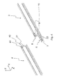
- Fig. 1 is the device 1, which consists of a first connecting means or rail element 6 and a second connecting means 8, shown.
- the device 1 is connected to a first mobile protective wall element 2.
- the first connection means 6 has a rail-like middle region 7 and two support elements 16 arranged laterally thereon.
- the support elements 16 extend substantially in the X / Y plane and are spaced apart in the X direction by the rail-like central region 7.
- the X direction preferably corresponds to the depth direction
- the Y direction preferably corresponds to the longitudinal direction
- the Z direction preferably corresponds to the height direction.
- the reference numeral 18 denotes the upper-side surface of the first connecting means 6, which at least in sections, in particular in the region of the support elements 16, with the lower side of the protective wall element 2 can be brought into contact, which has a lower side (continuous) recess for this purpose.
- the second connecting means 8 is arranged at a distance from the first connecting means 6 on the mobile protective wall element 2 in the Z direction. It is in the elements 6, 8 and completely separate, separate components of the device 1.
- the second connecting means 8 is arranged frontally of the mobile protective wall element 2 and does not extend beyond this in the Z direction.
- the first connection means 6 extends many times further in the X and Y directions than the second connection means 8. According to the in Fig. 2 As shown, the underside surface 20 of the mobile protective wall element 2 can be seen, with which the in Fig. 1 shown top surface 18 of the first connecting means 6 is at least partially brought into contact. Furthermore, the underside surface of the first connecting means 6 is designated by the reference numeral 24.
- the underside surface 24 of the first connecting means 6 is preferably on a solid ground, such as a road, erectable.
- Reference numeral 19 denotes the underside surface of the support elements 16, and reference numeral 24 denotes a bottom surface of the rail 7.
- the latter surface 24 need not be continuous, but may - as shown - consist of a plurality of spaced-apart elements (transverse webs).
- FIG. 3 illustrated exploded view shows a mobile protective wall element 2, the first connecting means 6 and a special embodiment of the second connecting means 8. Furthermore, this representation can be seen from a bracing or pressing means 40, which is preferably designed as a screw.
- the pressing means 40 is preferably used for clamping two mobile protective wall elements 2, 4 in the direction of their longitudinal extent (see. FIGS. 4 et seq.). In the case of the retraction of a vehicle in the mobile protective wall, the pressing means 40 thus serves as a transmission element, by which the forces occurring on another mobile protective wall element 2, 4 are transferable.
- Reference numerals 12 and 14 denote the first and the second coupling region, respectively.
- the first coupling region 12 serves to connect a lower side frame part 13 of the protective wall element 2, which extends substantially in the wall longitudinal direction, to the first connection means 6.
- the second coupling region 14 serves to connect a substantially vertically extending end frame part 15 to the second connection means 8
- Frame parts 13, 15 are preferably formed in metal (steel).
- the frame part 15 has in this embodiment a hole 41 for passing the contact pressure means 40.
- the hole 41 is arranged such that the pressing means 40 also extends in an installed state with its longitudinal axis in the Y direction and is substantially adjacent to a corresponding hole of another mobile protective wall element through which the pressing means 40 also extends.
- the second connecting means 8 is formed according to this embodiment as a tubular element with a rectangular, in particular square, cross-section.
- the second connecting means 8 in this case has the pipe element forming wall portions 10, 11, wherein two wall portions 10 are arranged spaced apart by means of two wall portions 11.
- the wall parts 10 are each for abutment against a first frame wall 50 and a second frame wall 51 of the frame part 15.
- the two frame walls 50, 51 are aligned parallel or substantially parallel to each other. Therefore, the wall parts 10 of the second connecting means 8 are also aligned parallel or substantially parallel to each other.
- the distance between the wall portions 10 is determined by the wall portions 11 and corresponds to the distance between the opposing surfaces of the first frame wall 50 and the second frame wall 51st
- the second connecting means 8 in the wall parts 11 introduced openings or holes 42, which are connected to each other by means of a tubular means 44.
- the tubular means 44 is designed as a round tubular element, through which the pressing means 40 can extend therethrough or in which the pressing means 40 can be accommodated.
- a first mobile protective wall element 2 and a second mobile protective wall element 4 are shown.
- the first mobile protective wall element 2 is already at least partially coupled to the first and second connecting means 6, 8.
- both connecting means 6, 8 are superimposed and / or enclosed substantially or exactly half of their extent in the longitudinal direction Y by the first mobile protective wall element 2.
- the wall part 10 of the second connecting means 8 is only partially, in particular substantially or exactly half, superimposed by the second frame wall 51 in the Y direction.
- the remaining, not superimposed portion of the wall 10 is completely or substantially completely overlaid by the second frame 51 of the second mobile protective wall element 4.
- the second mobile protective wall element 4 also has a hole 41, through which the pressing means 40 can be guided at least partially.
- Fig. 5 a state is shown in which the first mobile protective wall element 2 and the second mobile protective wall element 4 are connected to each other by means of the first and second connecting means 6, 8 such that an offset of the protective wall elements 2, 4 to each other at least in the X direction and preferably also in Y- and / or Z-direction is excluded or prevented.
- the mobile protective wall elements 2, 4 have at their lower in the longitudinal direction Y extending frame members 13 arranged lateral support elements 17, which are designed to be brought into contact with a first connection means 6 and / or for direct contact with a substrate.
- the wall elements 2, 4 are secured in this way against tipping to the side.
- the mobile protective wall elements 2, 4 are also bounded by metallic frame parts 56.
- a packing 52 in particular of concrete, recycled plastic or a mixed / composite material is arranged between the upper frame part 56 and the lower frame part 13 of a mobile protective wall element 2, 4.
- Reflector elements 54 for reflecting light are arranged laterally in the area of the filling body 52.
- FIG. 6 is indicated by the area marked with the letter A, that in the FIGS. 7a and 7b Assigned arrangements are assigned to the designated location.
- Fig. 7a is a side view of a mobile protective wall element 14 with disposed thereon first and second connecting means 6, 8 reproduced.
- the first, at least partially rail-like extending connecting means 6 acts in a coupling region 12 with the second mobile protective wall element 4 surface contacting together.
- the reference numeral 53 denotes a mounting region which defines a recess, by means of which the accessibility to the pressure means 40 is made possible.
- Fig. 7b is a front view of the in Fig. 7a shown arrangement reproduced.
- the supporting elements 16 of the first connecting means 6 are superimposed contacting by the supporting elements 17 of the second mobile protective wall element 4.
- the first connecting means 6 has a first vertical wall portion 26, a second vertical wall portion 28 and a further horizontal wall portion 32, which together in cross section conversely, forming a U-shaped rail-like elevation to which the second mobile protective wall element 4 has at least partially form-fittingly complementary complementary walls 58, 60, 61.
- a positive connection between the first connecting means 6 and the second mobile protective wall element 4 is therefore created by the interaction of the walls 26, 28, 32 with the opposing walls 58, 60, 61.
- the reference numerals 45 and 46 designate a first, upper opening and a second, lower opening in the tubular second connecting means 8, wherein the openings 45, 46 or their edges are connected to one another in the vertical direction by the wall parts 10, 11.
- the openings 45, 46 are each aligned in the installation or installation state in a substantially horizontal plane.
- Fig. 7c a top view of two mobile protective wall elements 2, 4 is shown, wherein the second mobile protective wall element 4 is in contact with the second connecting means 8 and is spaced from the first mobile protective wall element 2.
- the second connection means 8 is arranged on a boundary wall 62 of the frame part 15.
- the boundary wall 62 preferably forms together with the first and second frame walls 50, 51 (see also FIG FIG. 3 ) a U-profile or a double-T profile of the frame part 15.
- Fig. 8a is indicated by the area marked with the letter B, that in the FIG. 8b imaged arrangements are attributed to the designated location.
- FIG. 8b Four different embodiments are shown.
- the two embodiments arranged on the left have the second connecting means 8 already described above, which has a tubular body.
- supporting elements 17 are arranged on both sides in comparison to the lower illustration on the mobile protective wall elements 2, 4. According to the lower left illustration, however, such supporting elements 17 are not absolutely necessary.
- a support can, for example, via the first connecting means 6 (see. Fig. 1 ) respectively.
- the second connecting means 8 are formed exclusively from the mutually substantially parallel wall elements 10.
- the wall elements 10 are not directly connected to each other, but fixed non-positively, positively and / or cohesively to the frame member 15, in particular welded.
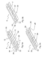
- FIG. 9a a first example of a concrete embodiment of the first connecting means 6 is shown.
- This connecting means 6 has between the support elements 16 on a rail-like portion 7, by two substantially in the Z direction extending, but slightly inclined relative to the Z direction wall portions 26, 28 and two of these wall portion 26, 28 each in an upper portion and / or in a lower portion connecting horizontal wall portions 32 is formed.
- the first and second wall portion 26, 28 are also arranged inclined to each other.
- the further wall sections 32 each extend in a horizontal plane and have connecting points 36 or holes, in particular holes of different sizes.
- FIG. 9b shown first connecting means 6 substantially corresponds to the in Fig. 9a
- Fig. 9c is still another first connecting means 6 shown.
- the rail-like portion 7 is formed only by three wall parts 26, 28, 32.
- the first and second walls 26, 28 are aligned substantially or exactly parallel to each other.
- the marked with the reference numeral 32 wall portion in this case has the direction indicated by the reference numeral 36 holes.
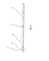
- FIG. 10a a side view of an extendable protective wall of elements 2, 4 is shown.
- the arrow C symbolizes the viewing direction for a variety of in the FIGS. 10b and 10c shown frontal views of the first connecting means. 6
- Fig. 10b is a side view of a first connecting means 6 and a plurality of different frontal views ad of the first connecting means 6 shown. Furthermore, two frontal views ef different trained frame parts 13 of the mobile protective wall elements 2, 4 are shown.
- the frontal view of the first connecting element 6 marked "a" has a rail-like portion which forms a substantially rectangular cross-section.
- the walls 26 and 28 are preferably identical. This is preferably the same for the walls 32, which are arranged at a constant distance from each other (see. FIG. 9b ).
- the walls 26 and 28 are inclined relative to one another (cf. FIG. 9a ). It can be seen that the walls 26 and 28 are arranged significantly closer to each other in an upper region than is the case in a further or lower region. As a result, the wall elements 32, which are preferably arranged parallel to one another, have different expansions in the X direction.
- a flat wall 32 is provided, through which two lower regions of an arcuate wall 27 are connected to one another.
- the walls 26 and 28 are arranged inclined relative to each other so that they touch in an upper area.
- a further wall 32 is provided, which connect the two inclined walls 26 and 28 with each other.
- the walls 26, 28 and 26, 28, 32 form a triangular or pyramidal profile.
- the two frontal views "e” and “f” of the mobile protective wall element 2, 4 differ only in that according to the variant “e” the opposing walls 60, 61 extend exclusively in the vertical direction, according to “f” still support elements 17 follow (see. FIG. 7b ).
- Fig. 10c is also a frontal view "a" of a first connecting means 6 (see. FIG. 9c ) and a frontal view "b" of a mobile protective wall element 2, 4.
- the variant shown in “a” corresponds essentially to the one in Fig. 10a with “a” marked variant, if this is performed without the upper wall 32.
- "a” is an open variant, in which the two wall parts 26 and 28 are opposite each other and define a receiving space into which a further body (the protective wall element) can be introduced.
- the body which can be introduced into the receiving space delimited by the wall parts 26 and 28 particularly preferably corresponds to the mobile protective wall element 2, 4 shown according to "b". Contrary to those shown in FIG Fig. 10b Variants shown in accordance with the in Fig. 10c variant shown a partial enclosure of the mobile protective wall element 2, 4 by the first connecting means 6th
- a first front view “a” and a second front view “f” of two first connection means 6 are shown.
- the frontal view labeled “a” is the same as in Fig. 10b with “b” designated variant.
- the frontal view labeled "f” is the same as in Fig. 10b with "a” designated variant.
- the mobile protective wall element 2, 4 forms a negative mold or complementary shape to the first connecting means 6 and is designed without lateral supporting elements 17.
- the frame part 13 of the mobile protective wall element 2, 4 is approximately omega-shaped and is in contact with the first connecting means 6 in the vertical direction only in a relatively small area, which extends substantially in the region of the lower wall 32. Due to the Omega shape, the frame part 13 forms lateral support elements, wherein it is also conceivable that these support elements 17 are arranged or arranged separately on the frame part 13.
- the frame part 13 is partially formed negative to the first connecting means 6 and is therefore in particular sections of the first connecting means 6 on.
- the frame part 13 has in this case on both sides of the rail-like element of the first connecting means 6 and arranged straight in the vertical direction extending wall portions, which are inclined downwardly to the vertical aligned Wandungsanteile.
- the inclined wall portions of the frame part 13 are in surface contact with the wall elements 26, 28 of the first connecting means 6.
- the support elements are formed such that they substantially or exactly completely overlay the support members 16 of the first connecting means 6.
- the frame member 13 is formed completely negative to the first connection means 6.
- the example “g” corresponds functionally to the example “b", wherein only the shape of the rail-like portion of the first connecting means 6 is different.
- the examples “h” and “i” have substantially or exactly negative to the first connecting means 6 formed frame parts 13.
- the frame parts 13 are likewise omega-shaped, wherein the resulting lateral support elements of the mobile protective wall elements in the example “h” only partially or in the example “i” substantially or exactly completely overlay the support elements 16 of the first connecting means 6.
- FIG. 12 different embodiments of first connecting means 6 and of frame elements 13 and mobile protective wall elements 2, 4 are shown.
- arrows are indicated, which indicate at which points the devices are in contact with each other or transmit forces to one another.
- the example “h” can be taken from a previously not yet mentioned coupling variant.
- a double “tongue and groove” connection is used.
- the mobile protective wall element 2, 4 is provided on the underside with a trapzeförmigen groove 64, and the first connecting means 6 has a complementary to the groove 64 spring 66.
Landscapes
- Engineering & Computer Science (AREA)
- Architecture (AREA)
- Civil Engineering (AREA)
- Structural Engineering (AREA)
- Refuge Islands, Traffic Blockers, Or Guard Fence (AREA)
- Details Of Indoor Wiring (AREA)
- Casings For Electric Apparatus (AREA)
- Finishing Walls (AREA)
- Fencing (AREA)
Applications Claiming Priority (1)
| Application Number | Priority Date | Filing Date | Title |
|---|---|---|---|
| DE202012009387U DE202012009387U1 (de) | 2012-10-01 | 2012-10-01 | Vorrichtung zum Verbinden zweier mobiler Schutzwandelemente |
Publications (4)
| Publication Number | Publication Date |
|---|---|
| EP2712962A2 true EP2712962A2 (fr) | 2014-04-02 |
| EP2712962A3 EP2712962A3 (fr) | 2016-11-23 |
| EP2712962B1 EP2712962B1 (fr) | 2018-04-11 |
| EP2712962B2 EP2712962B2 (fr) | 2022-03-02 |
Family
ID=47228817
Family Applications (1)
| Application Number | Title | Priority Date | Filing Date |
|---|---|---|---|
| EP13177998.5A Active EP2712962B2 (fr) | 2012-10-01 | 2013-07-25 | Dispositif destiné à relier deux éléments de paroi de protection mobiles |
Country Status (2)
| Country | Link |
|---|---|
| EP (1) | EP2712962B2 (fr) |
| DE (1) | DE202012009387U1 (fr) |
Cited By (3)
| Publication number | Priority date | Publication date | Assignee | Title |
|---|---|---|---|---|
| EP3587670A1 (fr) | 2018-06-29 | 2020-01-01 | GP Spolka z Ograniczona Odpowiedzialnoscia | Barrière de sécurité mobile et procédé pour assembler une barrière de sécurité mobile |
| EP3757292A1 (fr) * | 2019-06-27 | 2020-12-30 | Horst Luther | Élément de retenue pour une paroi de protection |
| EP3842593A1 (fr) | 2019-12-27 | 2021-06-30 | GP Spolka z Ograniczona Odpowiedzialnoscia | Barrière de sécurité mobile et procédé d'assemblage de barrière de sécurité mobile |
Families Citing this family (3)
| Publication number | Priority date | Publication date | Assignee | Title |
|---|---|---|---|---|
| DE202013000093U1 (de) | 2013-01-09 | 2013-01-23 | Horst Luther | Aufstell- und Haltevorrichtung für Verkehrseinrichtungen |
| DE102018119048A1 (de) * | 2018-08-06 | 2020-02-06 | AVS Verkehrssicherung GmbH | Wandelement für eine Verkehrsleit- und/oder absperrwand |
| CN110259047A (zh) * | 2019-06-27 | 2019-09-20 | 济南职业学院 | 一种基于时间序列分析的机动车车道控制的装置及方法 |
Citations (1)
| Publication number | Priority date | Publication date | Assignee | Title |
|---|---|---|---|---|
| DE202011104387U1 (de) | 2011-07-01 | 2011-11-16 | Horst Luther | Schutzwand aus einzelnen Schutzwandelementen zur Sicherung von Verkehrswegen |
Family Cites Families (11)
| Publication number | Priority date | Publication date | Assignee | Title |
|---|---|---|---|---|
| EP0462307B1 (fr) | 1990-06-21 | 1993-08-11 | SPIG SCHUTZPLANKEN-PRODUKTIONS-GESELLSCHAFT MBH & CO.KG | Tronçon de glissière de protection |
| DE9012472U1 (de) | 1990-08-31 | 1990-10-31 | SPIG Schutzplanken-Produktions-Gesellschaft mbH & Co KG, 6612 Schmelz | Leitschwellenstrang für Kraftfahrzeuge |
| DE4329547C1 (de) | 1993-09-02 | 1994-09-22 | Spig Schutzplanken Prod Gmbh | Stählerner Leitplankenstrang |
| FR2810055B1 (fr) * | 2000-06-08 | 2004-05-21 | Balisage Securite Service B S | Barriere de securite en beton pour voies routieres et autoroutieres |
| ATE267920T1 (de) | 2002-11-06 | 2004-06-15 | Spig Schutzplanken Prod Gmbh | Leitschwellenstrang aus stahl für kraftfahrzeuge |
| EP1693519B1 (fr) | 2005-01-20 | 2011-08-03 | Spig Schutzplanken-Produktions-Gesellschaft Mbh & Co. Kg | File de modules séparateurs pour limitation de voies de circulation |
| DE102007048304B3 (de) | 2007-10-08 | 2009-04-09 | Heintzmann Sicherheitssysteme Gmbh & Co. Kg | Fahrzeugrückhaltesystem |
| DE102007059873B4 (de) | 2007-12-12 | 2018-05-03 | Horst Luther | Schutzwandelement und Schutzwand zur Sicherung von Verkehrswegen |
| DE202010001863U1 (de) | 2010-02-05 | 2010-05-27 | Adolf Nissen Elektrobau Gmbh + Co. Kg | Verkehrsleitwand |
| DE202012003240U1 (de) | 2012-03-30 | 2012-05-07 | Horst Luther | Schutzwand und Schutzwandelement zur Herstellung einer solchen |
| DE202012004889U1 (de) | 2012-05-16 | 2012-07-03 | Horst Luther | Notöffnung für eine mobile Schutzwand |
-
2012
- 2012-10-01 DE DE202012009387U patent/DE202012009387U1/de not_active Expired - Lifetime
-
2013
- 2013-07-25 EP EP13177998.5A patent/EP2712962B2/fr active Active
Patent Citations (1)
| Publication number | Priority date | Publication date | Assignee | Title |
|---|---|---|---|---|
| DE202011104387U1 (de) | 2011-07-01 | 2011-11-16 | Horst Luther | Schutzwand aus einzelnen Schutzwandelementen zur Sicherung von Verkehrswegen |
Cited By (3)
| Publication number | Priority date | Publication date | Assignee | Title |
|---|---|---|---|---|
| EP3587670A1 (fr) | 2018-06-29 | 2020-01-01 | GP Spolka z Ograniczona Odpowiedzialnoscia | Barrière de sécurité mobile et procédé pour assembler une barrière de sécurité mobile |
| EP3757292A1 (fr) * | 2019-06-27 | 2020-12-30 | Horst Luther | Élément de retenue pour une paroi de protection |
| EP3842593A1 (fr) | 2019-12-27 | 2021-06-30 | GP Spolka z Ograniczona Odpowiedzialnoscia | Barrière de sécurité mobile et procédé d'assemblage de barrière de sécurité mobile |
Also Published As
| Publication number | Publication date |
|---|---|
| EP2712962A3 (fr) | 2016-11-23 |
| EP2712962B2 (fr) | 2022-03-02 |
| EP2712962B1 (fr) | 2018-04-11 |
| DE202012009387U1 (de) | 2012-10-25 |
Similar Documents
| Publication | Publication Date | Title |
|---|---|---|
| EP2712962B1 (fr) | Paroi de protection mobile | |
| DE102008023340A1 (de) | Aggregateträger für ein Getriebe eines Kraftfahrzeugs | |
| EP1927699B1 (fr) | Muret de séparation du trafic | |
| EP2851477B1 (fr) | Caniveau d'écoulement des eaux | |
| EP2567029B1 (fr) | Système de retenue pour véhicules au niveau de la chaussée | |
| DE202008011835U1 (de) | Stütze für Flüssigkeitsschutzwand | |
| CH636663A5 (en) | Road barrier device for keeping vehicles on a road | |
| DE102009011504B4 (de) | Fahrzeugrückhaltesystem aus Stahlblechen | |
| DE102005038150B4 (de) | Schlussquerträger für ein Nutzfahrzeug | |
| DE102007024993B4 (de) | Fahrzeug-Rückhaltesystem an Verkehrswegen | |
| DE102008026661B4 (de) | Verkehrsleitwand | |
| DE102007059873B4 (de) | Schutzwandelement und Schutzwand zur Sicherung von Verkehrswegen | |
| DE102008006251A1 (de) | Bodenbelag | |
| EP3502350B1 (fr) | Mur de guidage en béton | |
| EP2262953B1 (fr) | Système de retenue pour véhicule | |
| EP1888415B1 (fr) | Dispositif de transport conçu pour des elements de clôture et des pieds-supports | |
| DE29924191U1 (de) | Regal | |
| EP2333160A1 (fr) | Dispositif de guidage de la circulation | |
| EP0380955A1 (fr) | Rampe inclinée | |
| EP3312348A1 (fr) | Dispositif de protection de talus ainsi que talus formé d'éléments de talus | |
| EP2627828B1 (fr) | Pont modulaire et procédé d'assemblage d'éléments d'un tel pont | |
| DE102008007368A1 (de) | Unterfahrschutzvorrichtung | |
| EP3611305A1 (fr) | Élément mural pour un mur de gestion et/ou d'arrêt de trafic | |
| EP1734191B1 (fr) | Barrière de sécurité avec éléments en bois | |
| DE102006056182B4 (de) | Verkehrsleitwand |
Legal Events
| Date | Code | Title | Description |
|---|---|---|---|
| PUAI | Public reference made under article 153(3) epc to a published international application that has entered the european phase |
Free format text: ORIGINAL CODE: 0009012 |
|
| AK | Designated contracting states |
Kind code of ref document: A2 Designated state(s): AL AT BE BG CH CY CZ DE DK EE ES FI FR GB GR HR HU IE IS IT LI LT LU LV MC MK MT NL NO PL PT RO RS SE SI SK SM TR |
|
| AX | Request for extension of the european patent |
Extension state: BA ME |
|
| PUAL | Search report despatched |
Free format text: ORIGINAL CODE: 0009013 |
|
| AK | Designated contracting states |
Kind code of ref document: A3 Designated state(s): AL AT BE BG CH CY CZ DE DK EE ES FI FR GB GR HR HU IE IS IT LI LT LU LV MC MK MT NL NO PL PT RO RS SE SI SK SM TR |
|
| AX | Request for extension of the european patent |
Extension state: BA ME |
|
| RIC1 | Information provided on ipc code assigned before grant |
Ipc: E01F 15/08 20060101AFI20161018BHEP |
|
| STAA | Information on the status of an ep patent application or granted ep patent |
Free format text: STATUS: REQUEST FOR EXAMINATION WAS MADE |
|
| 17P | Request for examination filed |
Effective date: 20170117 |
|
| RBV | Designated contracting states (corrected) |
Designated state(s): AL AT BE BG CH CY CZ DE DK EE ES FI FR GB GR HR HU IE IS IT LI LT LU LV MC MK MT NL NO PL PT RO RS SE SI SK SM TR |
|
| STAA | Information on the status of an ep patent application or granted ep patent |
Free format text: STATUS: EXAMINATION IS IN PROGRESS |
|
| 17Q | First examination report despatched |
Effective date: 20170518 |
|
| GRAP | Despatch of communication of intention to grant a patent |
Free format text: ORIGINAL CODE: EPIDOSNIGR1 |
|
| STAA | Information on the status of an ep patent application or granted ep patent |
Free format text: STATUS: GRANT OF PATENT IS INTENDED |
|
| INTG | Intention to grant announced |
Effective date: 20171024 |
|
| GRAS | Grant fee paid |
Free format text: ORIGINAL CODE: EPIDOSNIGR3 |
|
| GRAA | (expected) grant |
Free format text: ORIGINAL CODE: 0009210 |
|
| STAA | Information on the status of an ep patent application or granted ep patent |
Free format text: STATUS: THE PATENT HAS BEEN GRANTED |
|
| AK | Designated contracting states |
Kind code of ref document: B1 Designated state(s): AL AT BE BG CH CY CZ DE DK EE ES FI FR GB GR HR HU IE IS IT LI LT LU LV MC MK MT NL NO PL PT RO RS SE SI SK SM TR |
|
| REG | Reference to a national code |
Ref country code: GB Ref legal event code: FG4D Free format text: NOT ENGLISH |
|
| REG | Reference to a national code |
Ref country code: CH Ref legal event code: EP |
|
| REG | Reference to a national code |
Ref country code: AT Ref legal event code: REF Ref document number: 988163 Country of ref document: AT Kind code of ref document: T Effective date: 20180415 |
|
| REG | Reference to a national code |
Ref country code: IE Ref legal event code: FG4D Free format text: LANGUAGE OF EP DOCUMENT: GERMAN |
|
| REG | Reference to a national code |
Ref country code: DE Ref legal event code: R096 Ref document number: 502013009878 Country of ref document: DE |
|
| REG | Reference to a national code |
Ref country code: FR Ref legal event code: PLFP Year of fee payment: 6 |
|
| REG | Reference to a national code |
Ref country code: NL Ref legal event code: MP Effective date: 20180411 |
|
| REG | Reference to a national code |
Ref country code: NO Ref legal event code: T2 Effective date: 20180411 Ref country code: LT Ref legal event code: MG4D |
|
| PG25 | Lapsed in a contracting state [announced via postgrant information from national office to epo] |
Ref country code: NL Free format text: LAPSE BECAUSE OF FAILURE TO SUBMIT A TRANSLATION OF THE DESCRIPTION OR TO PAY THE FEE WITHIN THE PRESCRIBED TIME-LIMIT Effective date: 20180411 |
|
| REG | Reference to a national code |
Ref country code: SK Ref legal event code: T3 Ref document number: E 27639 Country of ref document: SK |
|
| PG25 | Lapsed in a contracting state [announced via postgrant information from national office to epo] |
Ref country code: AL Free format text: LAPSE BECAUSE OF FAILURE TO SUBMIT A TRANSLATION OF THE DESCRIPTION OR TO PAY THE FEE WITHIN THE PRESCRIBED TIME-LIMIT Effective date: 20180411 Ref country code: FI Free format text: LAPSE BECAUSE OF FAILURE TO SUBMIT A TRANSLATION OF THE DESCRIPTION OR TO PAY THE FEE WITHIN THE PRESCRIBED TIME-LIMIT Effective date: 20180411 Ref country code: BG Free format text: LAPSE BECAUSE OF FAILURE TO SUBMIT A TRANSLATION OF THE DESCRIPTION OR TO PAY THE FEE WITHIN THE PRESCRIBED TIME-LIMIT Effective date: 20180711 Ref country code: LT Free format text: LAPSE BECAUSE OF FAILURE TO SUBMIT A TRANSLATION OF THE DESCRIPTION OR TO PAY THE FEE WITHIN THE PRESCRIBED TIME-LIMIT Effective date: 20180411 Ref country code: SE Free format text: LAPSE BECAUSE OF FAILURE TO SUBMIT A TRANSLATION OF THE DESCRIPTION OR TO PAY THE FEE WITHIN THE PRESCRIBED TIME-LIMIT Effective date: 20180411 Ref country code: ES Free format text: LAPSE BECAUSE OF FAILURE TO SUBMIT A TRANSLATION OF THE DESCRIPTION OR TO PAY THE FEE WITHIN THE PRESCRIBED TIME-LIMIT Effective date: 20180411 Ref country code: PL Free format text: LAPSE BECAUSE OF FAILURE TO SUBMIT A TRANSLATION OF THE DESCRIPTION OR TO PAY THE FEE WITHIN THE PRESCRIBED TIME-LIMIT Effective date: 20180411 |
|
| PG25 | Lapsed in a contracting state [announced via postgrant information from national office to epo] |
Ref country code: GR Free format text: LAPSE BECAUSE OF FAILURE TO SUBMIT A TRANSLATION OF THE DESCRIPTION OR TO PAY THE FEE WITHIN THE PRESCRIBED TIME-LIMIT Effective date: 20180712 Ref country code: LV Free format text: LAPSE BECAUSE OF FAILURE TO SUBMIT A TRANSLATION OF THE DESCRIPTION OR TO PAY THE FEE WITHIN THE PRESCRIBED TIME-LIMIT Effective date: 20180411 Ref country code: HR Free format text: LAPSE BECAUSE OF FAILURE TO SUBMIT A TRANSLATION OF THE DESCRIPTION OR TO PAY THE FEE WITHIN THE PRESCRIBED TIME-LIMIT Effective date: 20180411 Ref country code: RS Free format text: LAPSE BECAUSE OF FAILURE TO SUBMIT A TRANSLATION OF THE DESCRIPTION OR TO PAY THE FEE WITHIN THE PRESCRIBED TIME-LIMIT Effective date: 20180411 |
|
| PG25 | Lapsed in a contracting state [announced via postgrant information from national office to epo] |
Ref country code: PT Free format text: LAPSE BECAUSE OF FAILURE TO SUBMIT A TRANSLATION OF THE DESCRIPTION OR TO PAY THE FEE WITHIN THE PRESCRIBED TIME-LIMIT Effective date: 20180813 |
|
| REG | Reference to a national code |
Ref country code: DE Ref legal event code: R026 Ref document number: 502013009878 Country of ref document: DE |
|
| PLBI | Opposition filed |
Free format text: ORIGINAL CODE: 0009260 |
|
| PLAX | Notice of opposition and request to file observation + time limit sent |
Free format text: ORIGINAL CODE: EPIDOSNOBS2 |
|
| PG25 | Lapsed in a contracting state [announced via postgrant information from national office to epo] |
Ref country code: RO Free format text: LAPSE BECAUSE OF FAILURE TO SUBMIT A TRANSLATION OF THE DESCRIPTION OR TO PAY THE FEE WITHIN THE PRESCRIBED TIME-LIMIT Effective date: 20180411 Ref country code: DK Free format text: LAPSE BECAUSE OF FAILURE TO SUBMIT A TRANSLATION OF THE DESCRIPTION OR TO PAY THE FEE WITHIN THE PRESCRIBED TIME-LIMIT Effective date: 20180411 Ref country code: EE Free format text: LAPSE BECAUSE OF FAILURE TO SUBMIT A TRANSLATION OF THE DESCRIPTION OR TO PAY THE FEE WITHIN THE PRESCRIBED TIME-LIMIT Effective date: 20180411 |
|
| 26 | Opposition filed |
Opponent name: ADOLF NISSEN ELEKTROBAU GMBH + CO. KG Effective date: 20190109 |
|
| PG25 | Lapsed in a contracting state [announced via postgrant information from national office to epo] |
Ref country code: IT Free format text: LAPSE BECAUSE OF FAILURE TO SUBMIT A TRANSLATION OF THE DESCRIPTION OR TO PAY THE FEE WITHIN THE PRESCRIBED TIME-LIMIT Effective date: 20180411 Ref country code: SM Free format text: LAPSE BECAUSE OF FAILURE TO SUBMIT A TRANSLATION OF THE DESCRIPTION OR TO PAY THE FEE WITHIN THE PRESCRIBED TIME-LIMIT Effective date: 20180411 |
|
| REG | Reference to a national code |
Ref country code: CH Ref legal event code: PL |
|
| GBPC | Gb: european patent ceased through non-payment of renewal fee |
Effective date: 20180725 |
|
| PG25 | Lapsed in a contracting state [announced via postgrant information from national office to epo] |
Ref country code: MC Free format text: LAPSE BECAUSE OF FAILURE TO SUBMIT A TRANSLATION OF THE DESCRIPTION OR TO PAY THE FEE WITHIN THE PRESCRIBED TIME-LIMIT Effective date: 20180411 Ref country code: LU Free format text: LAPSE BECAUSE OF NON-PAYMENT OF DUE FEES Effective date: 20180725 |
|
| REG | Reference to a national code |
Ref country code: BE Ref legal event code: MM Effective date: 20180731 |
|
| REG | Reference to a national code |
Ref country code: IE Ref legal event code: MM4A |
|
| PG25 | Lapsed in a contracting state [announced via postgrant information from national office to epo] |
Ref country code: GB Free format text: LAPSE BECAUSE OF NON-PAYMENT OF DUE FEES Effective date: 20180725 Ref country code: CH Free format text: LAPSE BECAUSE OF NON-PAYMENT OF DUE FEES Effective date: 20180731 Ref country code: LI Free format text: LAPSE BECAUSE OF NON-PAYMENT OF DUE FEES Effective date: 20180731 Ref country code: IE Free format text: LAPSE BECAUSE OF NON-PAYMENT OF DUE FEES Effective date: 20180725 |
|
| PG25 | Lapsed in a contracting state [announced via postgrant information from national office to epo] |
Ref country code: SI Free format text: LAPSE BECAUSE OF FAILURE TO SUBMIT A TRANSLATION OF THE DESCRIPTION OR TO PAY THE FEE WITHIN THE PRESCRIBED TIME-LIMIT Effective date: 20180411 Ref country code: BE Free format text: LAPSE BECAUSE OF NON-PAYMENT OF DUE FEES Effective date: 20180731 |
|
| PLBB | Reply of patent proprietor to notice(s) of opposition received |
Free format text: ORIGINAL CODE: EPIDOSNOBS3 |
|
| PG25 | Lapsed in a contracting state [announced via postgrant information from national office to epo] |
Ref country code: MT Free format text: LAPSE BECAUSE OF FAILURE TO SUBMIT A TRANSLATION OF THE DESCRIPTION OR TO PAY THE FEE WITHIN THE PRESCRIBED TIME-LIMIT Effective date: 20180411 |
|
| PG25 | Lapsed in a contracting state [announced via postgrant information from national office to epo] |
Ref country code: TR Free format text: LAPSE BECAUSE OF FAILURE TO SUBMIT A TRANSLATION OF THE DESCRIPTION OR TO PAY THE FEE WITHIN THE PRESCRIBED TIME-LIMIT Effective date: 20180411 |
|
| PG25 | Lapsed in a contracting state [announced via postgrant information from national office to epo] |
Ref country code: HU Free format text: LAPSE BECAUSE OF FAILURE TO SUBMIT A TRANSLATION OF THE DESCRIPTION OR TO PAY THE FEE WITHIN THE PRESCRIBED TIME-LIMIT; INVALID AB INITIO Effective date: 20130725 |
|
| PG25 | Lapsed in a contracting state [announced via postgrant information from national office to epo] |
Ref country code: CY Free format text: LAPSE BECAUSE OF FAILURE TO SUBMIT A TRANSLATION OF THE DESCRIPTION OR TO PAY THE FEE WITHIN THE PRESCRIBED TIME-LIMIT Effective date: 20180411 Ref country code: MK Free format text: LAPSE BECAUSE OF NON-PAYMENT OF DUE FEES Effective date: 20180411 |
|
| PG25 | Lapsed in a contracting state [announced via postgrant information from national office to epo] |
Ref country code: IS Free format text: LAPSE BECAUSE OF FAILURE TO SUBMIT A TRANSLATION OF THE DESCRIPTION OR TO PAY THE FEE WITHIN THE PRESCRIBED TIME-LIMIT Effective date: 20180811 |
|
| PLBP | Opposition withdrawn |
Free format text: ORIGINAL CODE: 0009264 |
|
| REG | Reference to a national code |
Ref country code: CH Ref legal event code: PK Free format text: BERICHTIGUNGEN |
|
| PUAH | Patent maintained in amended form |
Free format text: ORIGINAL CODE: 0009272 |
|
| STAA | Information on the status of an ep patent application or granted ep patent |
Free format text: STATUS: PATENT MAINTAINED AS AMENDED |
|
| RAP2 | Party data changed (patent owner data changed or rights of a patent transferred) |
Owner name: METON GMBH |
|
| RIN2 | Information on inventor provided after grant (corrected) |
Inventor name: LUTHER, HORST |
|
| 27A | Patent maintained in amended form |
Effective date: 20220302 |
|
| AK | Designated contracting states |
Kind code of ref document: B2 Designated state(s): AL AT BE BG CH CY CZ DE DK EE ES FI FR GB GR HR HU IE IS IT LI LT LU LV MC MK MT NL NO PL PT RO RS SE SI SK SM TR |
|
| REG | Reference to a national code |
Ref country code: DE Ref legal event code: R102 Ref document number: 502013009878 Country of ref document: DE |
|
| REG | Reference to a national code |
Ref country code: DE Ref legal event code: R081 Ref document number: 502013009878 Country of ref document: DE Owner name: METON GMBH, DE Free format text: FORMER OWNER: LUTHER, HORST, 55765 BIRKENFELD, DE |
|
| REG | Reference to a national code |
Ref country code: SK Ref legal event code: T5 Ref document number: E 27639 Country of ref document: SK |
|
| REG | Reference to a national code |
Ref country code: NO Ref legal event code: TB2 |
|
| REG | Reference to a national code |
Ref country code: AT Ref legal event code: PC Ref document number: 988163 Country of ref document: AT Kind code of ref document: T Owner name: METON GMBH, DE Effective date: 20230314 |
|
| PGFP | Annual fee paid to national office [announced via postgrant information from national office to epo] |
Ref country code: SK Payment date: 20250624 Year of fee payment: 13 |
|
| PGFP | Annual fee paid to national office [announced via postgrant information from national office to epo] |
Ref country code: DE Payment date: 20250618 Year of fee payment: 13 |
|
| PGFP | Annual fee paid to national office [announced via postgrant information from national office to epo] |
Ref country code: NO Payment date: 20250722 Year of fee payment: 13 |
|
| PGFP | Annual fee paid to national office [announced via postgrant information from national office to epo] |
Ref country code: FR Payment date: 20250723 Year of fee payment: 13 Ref country code: AT Payment date: 20250721 Year of fee payment: 13 |
|
| PGFP | Annual fee paid to national office [announced via postgrant information from national office to epo] |
Ref country code: CZ Payment date: 20250711 Year of fee payment: 13 |