EP2714248B1 - Mineralienabscheidung - Google Patents
Mineralienabscheidung Download PDFInfo
- Publication number
- EP2714248B1 EP2714248B1 EP12789960.7A EP12789960A EP2714248B1 EP 2714248 B1 EP2714248 B1 EP 2714248B1 EP 12789960 A EP12789960 A EP 12789960A EP 2714248 B1 EP2714248 B1 EP 2714248B1
- Authority
- EP
- European Patent Office
- Prior art keywords
- collection
- mineral
- filter
- hydrophobic
- processor
- Prior art date
- Legal status (The legal status is an assumption and is not a legal conclusion. Google has not performed a legal analysis and makes no representation as to the accuracy of the status listed.)
- Active
Links
Images






Classifications
-
- B—PERFORMING OPERATIONS; TRANSPORTING
- B03—SEPARATION OF SOLID MATERIALS USING LIQUIDS OR USING PNEUMATIC TABLES OR JIGS; MAGNETIC OR ELECTROSTATIC SEPARATION OF SOLID MATERIALS FROM SOLID MATERIALS OR FLUIDS; SEPARATION BY HIGH-VOLTAGE ELECTRIC FIELDS
- B03C—MAGNETIC OR ELECTROSTATIC SEPARATION OF SOLID MATERIALS FROM SOLID MATERIALS OR FLUIDS; SEPARATION BY HIGH-VOLTAGE ELECTRIC FIELDS
- B03C5/00—Separating dispersed particles from liquids by electrostatic effect
-
- B—PERFORMING OPERATIONS; TRANSPORTING
- B03—SEPARATION OF SOLID MATERIALS USING LIQUIDS OR USING PNEUMATIC TABLES OR JIGS; MAGNETIC OR ELECTROSTATIC SEPARATION OF SOLID MATERIALS FROM SOLID MATERIALS OR FLUIDS; SEPARATION BY HIGH-VOLTAGE ELECTRIC FIELDS
- B03D—FLOTATION; DIFFERENTIAL SEDIMENTATION
- B03D1/00—Flotation
- B03D1/001—Flotation agents
- B03D1/004—Organic compounds
- B03D1/0046—Organic compounds containing silicon
-
- B—PERFORMING OPERATIONS; TRANSPORTING
- B01—PHYSICAL OR CHEMICAL PROCESSES OR APPARATUS IN GENERAL
- B01D—SEPARATION
- B01D15/00—Separating processes involving the treatment of liquids with solid sorbents; Apparatus therefor
- B01D15/02—Separating processes involving the treatment of liquids with solid sorbents; Apparatus therefor with moving adsorbents
-
- B—PERFORMING OPERATIONS; TRANSPORTING
- B01—PHYSICAL OR CHEMICAL PROCESSES OR APPARATUS IN GENERAL
- B01D—SEPARATION
- B01D37/00—Processes of filtration
- B01D37/02—Precoating the filter medium; Addition of filter aids to the liquid being filtered
-
- B—PERFORMING OPERATIONS; TRANSPORTING
- B01—PHYSICAL OR CHEMICAL PROCESSES OR APPARATUS IN GENERAL
- B01D—SEPARATION
- B01D39/00—Filtering material for liquid or gaseous fluids
-
- B—PERFORMING OPERATIONS; TRANSPORTING
- B03—SEPARATION OF SOLID MATERIALS USING LIQUIDS OR USING PNEUMATIC TABLES OR JIGS; MAGNETIC OR ELECTROSTATIC SEPARATION OF SOLID MATERIALS FROM SOLID MATERIALS OR FLUIDS; SEPARATION BY HIGH-VOLTAGE ELECTRIC FIELDS
- B03B—SEPARATING SOLID MATERIALS USING LIQUIDS OR USING PNEUMATIC TABLES OR JIGS
- B03B1/00—Conditioning for facilitating separation by altering physical properties of the matter to be treated
- B03B1/04—Conditioning for facilitating separation by altering physical properties of the matter to be treated by additives
-
- B—PERFORMING OPERATIONS; TRANSPORTING
- B03—SEPARATION OF SOLID MATERIALS USING LIQUIDS OR USING PNEUMATIC TABLES OR JIGS; MAGNETIC OR ELECTROSTATIC SEPARATION OF SOLID MATERIALS FROM SOLID MATERIALS OR FLUIDS; SEPARATION BY HIGH-VOLTAGE ELECTRIC FIELDS
- B03C—MAGNETIC OR ELECTROSTATIC SEPARATION OF SOLID MATERIALS FROM SOLID MATERIALS OR FLUIDS; SEPARATION BY HIGH-VOLTAGE ELECTRIC FIELDS
- B03C1/00—Magnetic separation
- B03C1/005—Pretreatment specially adapted for magnetic separation
- B03C1/01—Pretreatment specially adapted for magnetic separation by addition of magnetic adjuvants
-
- B—PERFORMING OPERATIONS; TRANSPORTING
- B03—SEPARATION OF SOLID MATERIALS USING LIQUIDS OR USING PNEUMATIC TABLES OR JIGS; MAGNETIC OR ELECTROSTATIC SEPARATION OF SOLID MATERIALS FROM SOLID MATERIALS OR FLUIDS; SEPARATION BY HIGH-VOLTAGE ELECTRIC FIELDS
- B03C—MAGNETIC OR ELECTROSTATIC SEPARATION OF SOLID MATERIALS FROM SOLID MATERIALS OR FLUIDS; SEPARATION BY HIGH-VOLTAGE ELECTRIC FIELDS
- B03C5/00—Separating dispersed particles from liquids by electrostatic effect
- B03C5/02—Separators
-
- B—PERFORMING OPERATIONS; TRANSPORTING
- B03—SEPARATION OF SOLID MATERIALS USING LIQUIDS OR USING PNEUMATIC TABLES OR JIGS; MAGNETIC OR ELECTROSTATIC SEPARATION OF SOLID MATERIALS FROM SOLID MATERIALS OR FLUIDS; SEPARATION BY HIGH-VOLTAGE ELECTRIC FIELDS
- B03D—FLOTATION; DIFFERENTIAL SEDIMENTATION
- B03D1/00—Flotation
- B03D1/001—Flotation agents
- B03D1/004—Organic compounds
- B03D1/016—Macromolecular compounds
-
- B—PERFORMING OPERATIONS; TRANSPORTING
- B03—SEPARATION OF SOLID MATERIALS USING LIQUIDS OR USING PNEUMATIC TABLES OR JIGS; MAGNETIC OR ELECTROSTATIC SEPARATION OF SOLID MATERIALS FROM SOLID MATERIALS OR FLUIDS; SEPARATION BY HIGH-VOLTAGE ELECTRIC FIELDS
- B03D—FLOTATION; DIFFERENTIAL SEDIMENTATION
- B03D1/00—Flotation
- B03D1/02—Froth-flotation processes
- B03D1/023—Carrier flotation; Flotation of a carrier material to which the target material attaches
-
- B—PERFORMING OPERATIONS; TRANSPORTING
- B03—SEPARATION OF SOLID MATERIALS USING LIQUIDS OR USING PNEUMATIC TABLES OR JIGS; MAGNETIC OR ELECTROSTATIC SEPARATION OF SOLID MATERIALS FROM SOLID MATERIALS OR FLUIDS; SEPARATION BY HIGH-VOLTAGE ELECTRIC FIELDS
- B03D—FLOTATION; DIFFERENTIAL SEDIMENTATION
- B03D1/00—Flotation
- B03D1/14—Flotation machines
-
- B—PERFORMING OPERATIONS; TRANSPORTING
- B04—CENTRIFUGAL APPARATUS OR MACHINES FOR CARRYING-OUT PHYSICAL OR CHEMICAL PROCESSES
- B04C—APPARATUS USING FREE VORTEX FLOW, e.g. CYCLONES
- B04C1/00—Apparatus in which the main direction of flow follows a flat spiral ; so-called flat cyclones or vortex chambers
-
- B—PERFORMING OPERATIONS; TRANSPORTING
- B07—SEPARATING SOLIDS FROM SOLIDS; SORTING
- B07B—SEPARATING SOLIDS FROM SOLIDS BY SIEVING, SCREENING, SIFTING OR BY USING GAS CURRENTS; SEPARATING BY OTHER DRY METHODS APPLICABLE TO BULK MATERIAL, e.g. LOOSE ARTICLES FIT TO BE HANDLED LIKE BULK MATERIAL
- B07B1/00—Sieving, screening, sifting, or sorting solid materials using networks, gratings, grids, or the like
-
- C—CHEMISTRY; METALLURGY
- C02—TREATMENT OF WATER, WASTE WATER, SEWAGE, OR SLUDGE
- C02F—TREATMENT OF WATER, WASTE WATER, SEWAGE, OR SLUDGE
- C02F1/00—Treatment of water, waste water, or sewage
- C02F1/24—Treatment of water, waste water, or sewage by flotation
-
- C—CHEMISTRY; METALLURGY
- C22—METALLURGY; FERROUS OR NON-FERROUS ALLOYS; TREATMENT OF ALLOYS OR NON-FERROUS METALS
- C22B—PRODUCTION AND REFINING OF METALS; PRETREATMENT OF RAW MATERIALS
- C22B15/00—Obtaining copper
- C22B15/0063—Hydrometallurgy
-
- Y—GENERAL TAGGING OF NEW TECHNOLOGICAL DEVELOPMENTS; GENERAL TAGGING OF CROSS-SECTIONAL TECHNOLOGIES SPANNING OVER SEVERAL SECTIONS OF THE IPC; TECHNICAL SUBJECTS COVERED BY FORMER USPC CROSS-REFERENCE ART COLLECTIONS [XRACs] AND DIGESTS
- Y02—TECHNOLOGIES OR APPLICATIONS FOR MITIGATION OR ADAPTATION AGAINST CLIMATE CHANGE
- Y02W—CLIMATE CHANGE MITIGATION TECHNOLOGIES RELATED TO WASTEWATER TREATMENT OR WASTE MANAGEMENT
- Y02W30/00—Technologies for solid waste management
- Y02W30/50—Reuse, recycling or recovery technologies
- Y02W30/52—Mechanical processing of waste for the recovery of materials, e.g. crushing, shredding, separation or disassembly
-
- Y—GENERAL TAGGING OF NEW TECHNOLOGICAL DEVELOPMENTS; GENERAL TAGGING OF CROSS-SECTIONAL TECHNOLOGIES SPANNING OVER SEVERAL SECTIONS OF THE IPC; TECHNICAL SUBJECTS COVERED BY FORMER USPC CROSS-REFERENCE ART COLLECTIONS [XRACs] AND DIGESTS
- Y10—TECHNICAL SUBJECTS COVERED BY FORMER USPC
- Y10T—TECHNICAL SUBJECTS COVERED BY FORMER US CLASSIFICATION
- Y10T428/00—Stock material or miscellaneous articles
- Y10T428/29—Coated or structually defined flake, particle, cell, strand, strand portion, rod, filament, macroscopic fiber or mass thereof
- Y10T428/2982—Particulate matter [e.g., sphere, flake, etc.]
Definitions
- This invention relates generally to a method and apparatus for separating valuable material from unwanted material in a mixture, such as a pulp slurry.
- flotation is used to separate valuable or desired material from unwanted material.
- a mixture of water, valuable material, unwanted material, chemicals and air is placed into a flotation cell.
- the chemicals are used to make the desired material hydrophobic and the air is used to carry the material to the surface of the flotation cell.
- the hydrophobic material and the air bubbles collide they become attached to each other. The bubble rises to the surface carrying the desired material with it.
- EP 0 164 237 A2 discloses a froth flotation process for the beneficiation of fine coal, wherein rising air bubbles are used to attract coal particles, and polyorganosiloxanes are used as collectors to render the coal particles more hydrophobic in order to promote adhesion to the rising air bubbles.
- WO 2012/028701 A2 discloses a stable mixture comprising surface-modified particles obtained by reacting metal or semi-metal oxide particles with a silicone-containing compound, the silicone-containing compound carrying at least one alkoxy radical, at least one solvent and at least one surface-active substance.
- the surface-modified particles may be used for chemical, physical or biological test or separation processes.
- US 2010/0200510 A1 discloses a process for separating at least one hydrophobic material from a mixture comprising this at least one hydrophobic material and at least one hydrophilic material.
- the hydrophobic material for example mineral particles, are bound to a solid surface which has been rendered hydrophobic by, for example, trihalosilyl groups or trialkoxysilyl groups.
- the present invention provides mineral separation or filtration techniques based at least partly on using apparatus featuring a collection area comprising collection surfaces configured to contact with a mixture comprising water and valuable material, the valuable material comprising a plurality of mineral particles; and a synthetic material provided at least on the collection surfaces, the synthetic material comprising a plurality of molecules comprising a functional group configured to attract the mineral particles to the collection surfaces, wherein the functional group is configured to render the collection surfaces hydrophobic and wherein the synthetic material comprises a siloxane derivative.
- the functional group may include a chemical functional group for bonding the mineral particles to the molecules.
- the functional group may include an ionic group which is either anionic or cationic, including where the functional group includes one or more ions in carboxylic, sulfates, sulfonates, xanthates, dithiophosphates, thionocarbamates, thioureas, xanthogens, monothiophosphates, hydroquinones and polyamines.
- the list is not necessarily exhaustive.
- the synthetic material may be selected from a group consisting of polyamides, polyesters, polyurethanes, phenol-formaldehyde, urea-formaldehyde, melamine-formaldehyde, polyacetal, polyethylene, polyisobutylene, polyacrylonitrile, poly(vinyl chloride), polystyrene, poly(methyl methacrylates), poly(vinyl acetate), poly(vinylidene chloride), polyisoprene, polybutadiene, polyacrylates, poly(carbonate), and phenolic resin.
- the list is not necessarily exhaustive.
- the functional group is configured to render the collection surfaces hydrophobic
- the synthetic material may be selected from a group consisting of poly(dimethylsiloxane)and hydrophobically-modified ethyl hydroxyethyl cellulose polysiloxanates, or including where the mineral particles may include one or more hydrophobic molecular segments attached thereon.
- the synthetic material may include polysiloxanates, or hydroxyl-terminated polydimethylsiloxanes.
- the mixture may further include a plurality of collector molecules, and each of the collector molecules may include a hydrophobic molecular segment and an ionized group bonding to the mineral particle.
- the present invention also takes the form of a method featuring providing a collection area on a filter member, the collection area comprising collection surfaces configured to contact with a mixture comprising water and valuable material, the valuable material comprising a plurality of mineral particles; and providing a synthetic material at least on the collection surfaces, the synthetic material comprising a plurality of molecules comprising a functional group configured to bind the mineral particles to the collection surfaces, wherein the functional group is configured to render the collection surfaces hydrophobic and wherein the synthetic material comprises a siloxane derivative.
- the method may also include one or more of the other features set forth herein.
- the present invention may be configured to provide mineral separation or filtration techniques using functionalized membranes.
- the present invention consists of a new apparatus and process for recovering valuable materials comprisingmineral particles from mineral rich pulp slurry.
- This slurry could be any type of slurry being air conveyed ground minerals, for example, but according to the present invention the slurry is an aqueous mixture.
- This mineral rich slurry is put into contact with a functionalized polymer surface which has been engineered to attract the mineral of interest.
- the functionalized polymer surface may take the form of a synthetic bubble or bead in a cage, as well as a membrane or membrane structure that may take the form of an impeller, a conveyor belt or a filter.
- the functionalized polymer comprises a siloxane derivative, as will become apparent from the description which follows.
- the unwanted material may be washed away and only the desirable material or mineral is left on the functionalized polymer surface, or the membrane structure containing the functionalized polymer surface may be separated from the unwanted material. Such separation can take place via techniques related to flotation, size separation, gravimetric separation, and/or magnetic separation.
- the enriched surface is then treated so that the mineral is released and collected.
- the polymer surface can then be reused.
- the apparatus will be used in a system with two chambers, tanks, cells or columns.
- One chamber, tank, cell or column has an environment conducive to attachment of a valuable material or mineral or particle of interest and the other chamber, tank, cell or column has an environment conducive for release of the valuable material or mineral or particle of interest.
- An impeller may be coated with the functionalized polymer and configured to rotate slowly inside the two chambers, tanks, cells or columns. As an impeller blade moves into an attachment zone in the one chamber, tank, cell or column, it collects the valuable material or mineral or particle of interest. As the enriched blade moves to a release zone in the other chamber, tank, cell or column, the valuable material or mineral or particle of interest are released.
- a functionalized polymer conveyor belt may be configured to run between the two chambers, tanks, cells or columns, whereby it collects and releases the valuable material or mineral or particle of interest.
- a functionalized polymer collection filter may be placed into each chamber, tank, cell or column to collect and release the valuable material or mineral or particle of interest. This is a batch type process.
- the apparatus claimed in claim 1 and the method claimed in claim 10 may be used in or performed in, respectively, a mineral separation apparatus as described below.
- the present invention may be used or performed in a machine, system or apparatus featuring a first processor and a second processor.
- the first processor may be configured to receive a mixture of fluid, valuable material and unwanted material and the apparatus claimed in claim 1 in the form of a functionalized polymer coated member configured to attach to the valuable material in an attachment rich environment, and provide an enriched functionalized polymer coated member having the valuable material attached thereto.
- the second processor may be configured to receive a fluid and the enriched functionalized polymer coated member in a release rich environment to release the valuable material, and provide the valuable material released from the enriched functionalized polymer coated member to the release rich environment.
- a "member” means a conveyor belt, a filter, or an impeller.
- the mineral separation apparatus may be configured to include one or more of the following features:
- the first processor may take the form of a first chamber, tank, cell or column, and the second processor may take the form of a second chamber, tank, cell or column.
- the first chamber, tank or column may be configured to receive a pulp slurry having water, the valuable material and the unwanted material in the attachment rich environment, which has a high pH, conducive to attachment of the valuable material.
- the second chamber, tank or column may be configured to receive water in the release rich environment, which may have a low pH or receive ultrasonic waves conducive to release of the valuable material.
- the functionalized polymer coated member takes the form of a functionalized polymer coated impeller having at least one impeller blade configured to rotate slowly inside the first processor and the second processor.
- the first processor may be configured to receive the at least one impeller blade in an attachment zone, and provide at least one enriched impeller blade having the valuable material attached thereto in the attachment zone.
- the second processor may be configured to receive the at least one enriched impeller blade in a release zone and to provide the valuable material released from the at least one enriched impeller blade.
- the first processor may be configured with a first transition zone to provide drainage of tailings, and the second processor may be configured with a second transition zone to provide drainage of concentrate.
- the functionalized polymer coated member takes the form of a functionalized polymer coated conveyor belt configured to run between the first processor and the second processor.
- the first processor may be configured to receive the functionalized polymer coated conveyor belt and provide an enriched functionalized polymer coated conveyor belt having the valuable material attached thereto.
- the second processor may be configured to receive the enriched functionalized polymer coated conveyor belt and provide the valuable material released from the enriched functionalized polymer coated conveyor belt.
- the functionalized polymer coated conveyor belt may be made of a mesh material.
- the functionalized polymer coated member takes the form of a functionalized polymer coated collection filter configured to move between the first processor and the second processor as part of a batch type process.
- the first processor may be configured to receive the functionalized polymer coated collection filter and to provide an enriched functionalized polymer coated collection filter having the valuable material attached thereto.
- the second processor device may be configured to receive the enriched functionalized polymer coated collection filter and provide the valuable material released from the enriched functionalized polymer coated collection filter.
- the first processor may be configured to provide tailings containing the unwanted material
- the second processor may be configured to provide a concentrate containing the valuable material
- the functionalized polymer coated filter member takes the form of a membrane or a thin soft pliable sheet or layer.
- the present invention may also be used in a mineral separation apparatus featuring first means that may be configured to receive a mixture of fluid, valuable material and unwanted material and the apparatus claimed in claim 1 in the form of a functionalized polymer coated member configured to attach to the valuable material in an attachment rich environment, and provide an enriched functionalized polymer coated member having the valuable material attached thereto; and second means that may be configured to receive a fluid and the enriched functionalized polymer coated member in a release rich environment to release the valuable material, and provide the valuable material released from the enriched functionalized polymer coated member to the release rich environment.
- the first means may be configured to receive a pulp slurry having water, the valuable material and the unwanted material in the attachment rich environment, which has a high pH, conducive to attachment of the valuable material; and the second means may be configured to receive water in the release rich environment, which has a low pH or receives ultrasonic waves conducive to release of the valuable material.
- the functionalized polymer coated member may take the form of one of the following:
- the method of the present invention as claimed in claim 10 may be part of a mineral separation process or method featuring receiving in a first processor a mixture of fluid, valuable material and unwanted material and the apparatus claimed in claim 1 in the form of a functionalized polymer coated member configured to attach to the valuable material in an attachment rich environment, and providing from the first processor an enriched functionalized polymer coated member having the valuable material attached thereto; and receiving in a second processor a fluid and the enriched functionalized polymer coated member in a release rich environment to release the valuable material, and providing the valuable material released from the enriched functionalized polymer coated member to the release rich environment.
- the method of the present invention may include being implemented consistent with one or more of the features set forth herein.
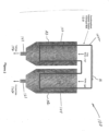
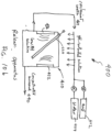
- Figure 1 shows an impeller of the present invention in a machine, device, system or apparatus 10, for separating valuable material from unwanted material in a mixture 11, such as a pulp slurry, using a first processor 12 and a second processor 14.
- the first processor 12 and the second processor 14 are configured with a functionalized polymer coated member that is shown, as a functionalized polymer coated impeller 20 ( Fig. 1a ), 20' ( Fig. 1b ), according to some embodiments of the present invention.
- the impeller 20, 20' slowly rotates in relation to the first processor 12 and the second processor 14, the impeller blades slowly pass through the attachment rich environment 16 in the first processor 12 where the valuable material is attached to the blades and through the release rich environment 18 in the second processor 14 is released from the blades.
- the impeller 20 is shown rotating in a counterclockwise direction as indicated by arrow a, although there is no limitation as regards the direction of the impeller rotation, or the manner in which the functionalized polymer coated impeller 20 ( Fig. 1a ), 20' ( Fig. 1b ) is arranged, mounted, or configured in relation to the first processor 12 and the second processor 14.
- the first processor 12 may take the form of a first chamber, tank, cell or column that contains an attachment rich environment generally indicated as 16.
- the first chamber, tank or column 12 may be configured to receive via piping 13 the mixture or pulp slurry 11 in the form of fluid (e.g., water), the valuable material and the unwanted material in the attachment rich environment 16, e.g., which has a high pH, conducive to attachment of the valuable material.
- the second processor 14 may take the form of a second chamber, tank, cell or column that contains a release rich environment generally indicated as 18.
- the second chamber, tank, cell or column 14 may be configured to receive via piping 15, e.g., water 22 in the release rich environment 18, e.g., which may have a low pH or receive ultrasonic waves conducive to release of the valuable material.
- Attachment rich environments like that forming part of element environment 16 conducive to the attachment of a valuable material of interest and release rich environments like that forming part of environment 18 conducive to the release of the valuable material of interest are known in the art, and there is no limitation as regards type or kind thereof.
- the first processor 12 may be configured to receive the mixture or pulp slurry 11 of water, valuable material and unwanted material and the functionalized polymer coated member that is configured to attach to the valuable material in the attachment rich environment 16.
- the functionalized polymer coated member is shown as the functionalized polymer coated impeller 20 ( Fig. 1a ), 20' ( Fig. 1b ).
- the functionalized polymer coated impeller 20 has a shaft 21 and at least one impeller blade 20a, 20b, 20c, 20d, 2e, 20f, 20g and is configured to rotate slowly inside the first processor 12 and the second processor 14.
- the functionalized polymer coated impeller 20' has a shaft 21' and impeller blades 20a', 20b', 20c', 20d', 2e', 20f', 20g' and 20h'.
- Each impeller blade in Figures 1 is understood to be configured and functionalized with a polymer coating to attach to the valuable material in the attachment rich environment 16. (The scope of the invention is not intended to be limited to the number of blades on the impeller 20, 20' and the embodiment in Figures 1a and 1b is shown with impellers 21, 21' having a different number of blades.)
- the first processor 12 is configured to receive at least one impeller blade of the functionalized polymer coated impeller 20 ( Fig. 1a ), 20' ( Fig. 1b ).
- the at least one impeller blade is shown as impeller blade 20g' being received in an attachment zone 30 that forms part of the attachment rich environment 16 defined by walls 30a, 30b.
- the first processor 12 may also be configured with a first transition zone generally indicated as 40 to provide drainage from piping 41 of, e.g., tailings 42 as shown in Figure 1a .
- the first processor 12 may also be configured to provide at least one enriched impeller blade having the valuable material attached thereto, after passing through the attachment rich environment 16.
- the at least one enriched impeller blade is shown as the at least one enriched impeller blade 20c' being provisioned from the attachment rich environment 16 in the first processor 12 to the release rich environment 18 in the second processor 14.
- the second processor 14 may be configured to receive via the piping 15 the fluid 22 (e.g. water) and the enriched functionalized polymer coated member to release the valuable material in the release rich environment 18.
- the second processor 14 is shown receiving the enriched impeller blade 20c' in a release zone 50, e.g., that forms part of the release rich environment 18 and is defined, e.g., by walls 30c and 30d.
- the second processor 14 may also be configured to provide the valuable material that is released from the enriched functionalized polymer coated member into the release rich environment 18.
- the second processor 14 is shown configured with a second transition zone 60 defined by walls 30a and 30d to provide via piping 61 drainage of the valuable material in the form of a concentrate 62 ( Fig. 1a ).
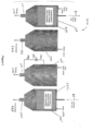
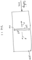
- Figure 2 shows a conveyor belt according to the present invention in a machine, device, system or apparatus 100, for separating valuable material from unwanted material in a mixture 101, such as a pulp slurry, using a first processor 102 and a second processor 104.
- the first processor 102 and the second processor 104 are configured with a functionalized polymer coated member that is shown, as a functionalized polymer coated conveyor belt 120 that runs between the first processor 102 and the second processor 104.
- the arrows A1, A2, A3 indicate the movement of the functionalized polymer coated conveyor belt 120.
- the functionalized polymer coated conveyor belt 120 may be made of a mesh material.
- the first processor 102 may take the form of a first chamber, tank, cell or column that contains an attachment rich environment generally indicated as 106.
- the first chamber, tank or column 102 may be configured to receive the mixture or pulp slurry 101 in the form of fluid (e.g., water), the valuable material and the unwanted material in the attachment rich environment 106, e.g., which has a high pH, conducive to attachment of the valuable material.
- the second processor 104 may take the form of a second chamber, tank, cell or column that contains a release rich environment generally indicated as 108.
- the second chamber, tank, cell or column 104 may be configured to receive, e.g., water 122 in the release rich environment 108, e.g., which may have a low pH or receive ultrasonic waves conducive to release of the valuable material.
- water 122 in the release rich environment 108
- the second chamber, tank, cell or column 104 may be configured to receive, e.g., water 122 in the release rich environment 108, e.g., which may have a low pH or receive ultrasonic waves conducive to release of the valuable material.
- attachment rich environments like that forming part of element environment 106 conducive to the attachment of a valuable material of interest and release rich environments like that forming part of environment 108 conducive to the release of the valuable material of interest are known in the art, and there is no limitation as regards type or kind thereof.
- an attachment rich environment like environment 106 and a corresponding release rich environment like environment 108 based on the separation technology disclosed herein for any particular valuable mineral of interest, e.g., copper, forming part of any particular mixture or slurry pulp.
- the first processor 102 may be configured to receive the mixture or pulp slurry 101 of water, valuable material and unwanted material and the functionalized polymer coated conveyor belt 120 that is configured to attach to the valuable material in the attachment rich environment 106.
- the belt 120 is understood to be configured and functionalized with a polymer coating to attach to the valuable material in the attachment rich environment 106.
- the first processor 102 may also be configured to provide drainage from piping 141 of, e.g., tailings 142 as shown in Figure 2 .
- the first processor 102 may also be configured to provide an enriched functionalized polymer coated conveyor belt having the valuable material attached thereto, after passing through the attachment rich environment 106.
- the enriched functionalized polymer coated conveyor belt is shown, e.g., as that portion or part 120a of the belt 120 being provisioned from the attachment rich environment 106 in the first processor 102 to the release rich environment 108 in the second processor 104. It is understood that some other portions or parts of the belt 120 may be enriched, including the portion or part immediately leaving the attachment rich environment 106, as well as the portion or part immediately entering the release rich environment 108.
- the second processor 14 may be configured to receive the fluid 122 (e.g. water) and the portion 120a of the enriched functionalized polymer coated conveyor belt 120 to release the valuable material in the release rich environment 108.
- the fluid 122 e.g. water
- the second processor 104 may also be configured to provide the valuable material that is released from the enriched functionalized polymer coated member into the release rich environment 108.
- the second processor 104 is shown configured to provide via piping 161 drainage of the valuable material in the form of a concentrate 162.
- the first processor 102 is configured with the functionalized polymer coated conveyor belt 120 passing through with only two turns inside the attachment rich environment 106.
- the first processor 102 may be configured to process the functionalized polymer coated conveyor belt 120 using a serpentine technique for winding or turning the belt 120 one way and another way, back and forth, inside the first processor to maximize surface area of the belt inside the processor 102 and exposure of the belt 120 to the attachment rich environment 106.
- Figure 3 shows a filter according to the present invention in a machine, device, system or apparatus 200, for separating valuable material from unwanted material in a mixture 201, such as a pulp slurry, using a first processor 202, 202' and a second processor 204, 204'.
- the first processor 202 and the second processor 204 are configured to process a functionalized polymer coated member that is shown, as a functionalized polymer coated collection filter 220 according to the invention, configured to be moved between the first processor 202 and the second processor 204' as shown in Figure 3 as part of a batch type process.
- the batch type process is shown as having two first processor 202, 202' and second processor 204, 204, although there is no limitation as regards the number of first or second processors. Moreover, embodiments are envisioned using a different number of first and second processor, different types or kinds of processors, as well as different types or kinds of processors.
- the functionalized polymer coated collection filter 220 may take the form of a membrane or a thin soft pliable sheet or layer.
- the arrow B1 indicates the movement of the functionalized polymer coated filter 220 from the first processor 202, and the arrow B2 indicates the movement of the functionalized polymer coated collection filter 220 into the second processor 202.
- Techniques, including motors, gearing, etc., for moving a filter like element 220 from one processor to another processor like elements 202 and 204 are known in the art, and there is no limitation as regards type or kind thereof.
- the first processor 202 may take the form of a first chamber, tank, cell or column that contains an attachment rich environment generally indicated as 206.
- the first chamber, tank or column 102 may be configured to receive the mixture or pulp slurry 201 in the form of fluid (e.g., water), the valuable material and the unwanted material in the attachment rich environment 206, e.g., which has a high pH, conducive to attachment of the valuable material.
- the second processor 204 may take the form of a second chamber, tank, cell or column that contains a release rich environment generally indicated as 208.
- the second chamber, tank, cell or column 204 may be configured to receive, e.g., water 222 in the release rich environment 208, e.g., which may have a low pH or receive ultrasonic waves conducive to release of the valuable material.
- the release rich environment 208 e.g., which may have a low pH or receive ultrasonic waves conducive to release of the valuable material.
- an attachment rich environment like environment 206 and a corresponding release rich environment like environment 208 based on the separation technology disclosed herein for any particular valuable mineral of interest, e.g., copper, forming part of any particular mixture or slurry pulp.
- the first processor 202 may be configured to receive the mixture or pulp slurry 101 of water, valuable material and unwanted material and the functionalized polymer coated collection filter 220 that is configured to attach to the valuable material in the attachment rich environment 206.
- the functionalized polymer coated collection filter 220 is understood to be configured and functionalized with a polymer coating to attach to the valuable material in the attachment rich environment 106.
- the first processor 202 may also be configured to provide drainage from piping 241 of, e.g., tailings 242 as shown in Figure 3 .
- the first processor 202 may also be configured to provide an enriched functionalized polymer coated collection filter having the valuable material attached thereto, after soaking in the attachment rich environment 106.
- the enriched functionalized polymer coated collection filter 220 is shown, e.g., being provisioned from the attachment rich environment 206 in the first processor 202 to the release rich environment 208 in the second processor 204.
- the second processor 204 may be configured to receive the fluid 222 (e.g. water) and the enriched functionalized polymer coated collection filter 220 to release the valuable material in the release rich environment 208.
- the fluid 222 e.g. water
- the enriched functionalized polymer coated collection filter 220 may be configured to release the valuable material in the release rich environment 208.
- the second processor 204 may also be configured to provide the valuable material that is released from the enriched functionalized polymer coated collection filter 220 into the release rich environment 208.
- the second processor 204 is shown configured to provide via piping 261 drainage of the valuable material in the form of a concentrate 262.
- the first processor 202' may also be configured with piping 280 and pumping 280 to recirculate the tailings 242 back into the first processor 202'.
- the second processor 204' may also be configured with corresponding piping and pumping to recirculate the concentrate 262 back into the second processor 204'. Similar recirculation techniques may be implemented for the embodiments disclosed in relation to Figures 1-2 above.
- the batch process may include the first and second processors 202, 204 being configured to process the enriched functionalized polymer coated collection filter 220 in relation to one type or kind of valuable material, and the first and second processors 202', 204' being configured to process the enriched functionalized polymer coated collection filter 220 in relation to either the same type or kind of valuable material, or a different type or kind of valuable material.
- the polymer at least can be functionalized to attract particles in two different ways.
- polymer in this disclosure means a large molecule made of many units of the same or similar structure linked together.
- the polymer surface on a filter has a plurality of molecules 73 ( Figures 8a , 9a ) having a functional group 78 ( Figures 8a, 8b ) to attract mineral particles 72 ( Figures 8a , 9a ).
- the unit can be a monomer or an oligomer which forms the basis of, for example, polyamides (nylon), polyesters, polyurethanes, phenol-formaldehyde, urea-formaldehyde, melamine-formaldehyde, polyacetal, polyethylene, polyisobutylene, polyacrylonitrile, poly(vinyl chloride), polystyrene, poly(methyl methacrylates), poly(vinyl acetate), poly(vinylidene chloride), polyisoprene, polybutadiene, polyacrylates, poly(carbonate), phenolic resin, polydimethylsiloxane and other organic or inorganic polymers.
- polyamides nylon
- polyesters polyurethanes
- phenol-formaldehyde urea-formaldehyde
- melamine-formaldehyde polyacetal
- polyethylene polyisobutylene
- polyacrylonitrile poly(vinyl chloride
- the synthetic material can be hard or rigid like plastic or soft and flexible like an elastomer. While the physical properties of the filter can vary, the surface of the filter is chemically functionalized to provide a plurality of functional groups to attract mineral particles, i.e. the synthetic material comprises a plurality of molecules comprising a functional group configured to attract the mineral particles to the collection surfaces, wherein the functional group is configured to render the collection surfaces hydrophobic, and the synthetic material configures a siloxane derivative.
- the terms "valuable material” and “mineral particle” are used herein interchangeably. It is possible to use a molecule or molecular segment 76 ( Figure 8a , 9a ) to attach a functional group 78 to the polymer surface.
- the molecule 76 can be a hydrocarbon chain, for example, and the functional group 78 can be ionic for attracting a mineral, such as copper to the surface 74.
- a xanthate for example, has both the functional group 78 and the molecular segment 76 to be incorporated into the polymer that is used to make or coat the surface.
- a functional group 78 is also known as a collector that is either ionic or non-ionic.
- the ion can be anionic or cationic.
- An anion includes, but not limited to, oxyhydryl, such as carboxylic, sulfates and sulfonates, and sulfhydral, such as xanthates and dithiophosphates.
- thionocarbamates include thioureas, xanthogens, monothiophosphates, hydroquinones and polyamines.
- a chelating agent can be incorporated into the polymer as a collector site for attaching to a mineral, such as copper.
- a surface having a functionalized polymer is also referred herein as synthetic surface.
- At least the surface of a filter surface is functionalized so that the surface is hydrophobic. It is possible to functionalize a polymer surface to have a plurality of molecules 79 ( Figures 8b, 8c , 9b, 9c ) to render the surface hydrophobic.
- hydrophobicity is the physical property of a molecule (known as a hydrophobe) that is repelled from a mass of water. Hydrophobic molecules tend to be non-polar and, thus, prefer other neutral molecules and non-polar solvents. Hydrophobic molecules in water often cluster together. According to thermodynamics, matter seeks to be in a low-energy state, and bonding reduces chemical energy. Water is electrically polarized, and is able to form hydrogen bonds internally, which gives it many of its unique physical properties. But, since hydrophobes are not electrically polarized, and because they are unable to form hydrogen bonds, water repels hydrophobes, in favor of bonding with itself. It is this effect that causes the hydrophobic interaction.
- the hydrophobic effect is the observed tendency of nonpolar substances to aggregate in aqueous solution and exclude water molecules. It can be observed as the segregation and apparent repulsion between water and non-polar substances.
- the hydrophobic interaction is mostly an entropic effect originating from the disruption of hydrogen bonds between molecules of liquid water by the non-polar solute.
- a hydrocarbon chain or a similar non-polar region or a big molecule is incapable of forming hydrogen bonds with water.
- the introduction of such a non-hydrogen bonding surface into water causes disruption of the hydrogen bonding network between water molecules. By aggregating together, nonpolar molecules reduce the surface area exposed to water and minimize their disruptive effect.
- Froth flotation is a process for selectively separating hydrophobic materials from hydrophilic.
- the process has been adapted and applied to a wide variety of materials to be separated, and additional collector agents, including surfactants and synthetic compounds have been adopted for various applications.
- froth flotation is a process for separating minerals from gangue by taking advantage of differences in their hydrophobicity. Hydrophobicity differences between valuable minerals and waste gangue are increased through the use of surfactants and wetting agents. The selective separation of the minerals makes processing complex (that is, mixed) ores economically feasible.
- the flotation process is used for the separation of a large range of sulfides, carbonates and oxides prior to further refinement. Phosphates and coal are also upgraded (purified) by flotation technology.
- Froth flotation commences by comminution (that is, crushing and grinding), which is used to increase the surface area of the ore for subsequent processing. The ore include the desired minerals and other unwanted materials, know a gangue.
- the process of grinding the ore into a fine power is known as liberation.
- the fine powder ore is then mixed with water to form a slurry.
- the desired mineral is rendered hydrophobic by the addition of a surfactant or collector chemical. The particular chemical depends on which mineral is being refined.
- This slurry (more properly called the pulp) of hydrophobic mineral particles and hydrophilic gangue particles is then placed in a flotation column or horizontal pipeline wherein the concentrated mineral is separated from the tailings containing the gangue.
- the collectors are chosen based upon their selective wetting of the types of particles to be separated. A good collector will adsorb, physically or chemically, with one of the types of particles.
- a flotation circuit for mineral concentration various flotation reagents are added to a mixture of ore and water (called pulp) in a conditioning tank.
- the flow rate and tank size are designed to give the minerals enough time to be activated.
- the conditioner pulp is fed to a bank of rougher cells which remove most of the desired minerals as a concentrate.
- the rougher pulp passes to a bank of scavenger cells where additional reagents may be added.
- the scavenger cell froth is usually returned to the rougher cells for additional treatment, but in some cases may be sent to special cleaner cells.
- the scavenger pulp is usually barren enough to be discarded as tails.
- More complex flotation circuits have several sets of cleaner and re-cleaner cells, and intermediate re-grinding of pulp or concentrate. Because of a number of other factors, as much as 15% of the liberated minerals are not recovered and are discarded as gangue.
- Collectors either chemically bond (chemisorption) on a hydrophobic mineral surface, or adsorb onto the surface in the case of, for example, coal flotation through physisorption. Collectors increase the natural hydrophobicity of the surface, increasing the separability of the hydrophobic and hydrophilic particles.
- the hydrophobic particles of interest are depicted as particles 71', 72' in Figures 8b, 8c , 9b and 9c .
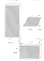
- the impeller 20 has a collection area 23 to support the functionalized polymer ( Figure 4 ).
- the conveyor belt 120 has a collection area 123 to support the functionalized polymer ( Figure 5 ).
- the filter 220 has a collection area 223 to support the functional polymer ( Figure 6 ).
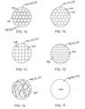
- the collection area 23, 123 and 223 can take many forms and have various surface features ( Figures 7a-7f ) to attract the mineral particles of interest, when the impeller 20, conveyor belt 120 and the filter 220 are made contact with a mixture or pulp slurry 11 ( Figure 1 ), 101 ( Figure 2 ), 201 ( Figure 3 ) that includes water and valuable material.
- each of the collection areas 23, 123 and 223 may have a plurality of openings to allow the pulp slurry 11 ( Figure 1 ), 101 ( Figure 2 ), 201 ( Figure 3 ) to pass through while collecting at least part of the valuable material comprising a plurality of mineral particles in the pulp slurry.
- the surface inside an opening and the surfaces or edges around the opening will be provided with the functional groups to attract the mineral particles. Those surfaces are referred to as collection surfaces.
- the openings on the collection areas 23, 123 and 223 can take the form of holes or cylindrical passage ways 701 as shown in Figure 7a .
- the openings on the collection areas 23, 123 and 223 can take the form of hexagonal passage ways 702 arranged like honeycomb, as shown in Figure 7b .
- the collection areas 23, 123 and 223 can have a rectangular grid 703, as shown in Figure 7c .
- the collection areas 23, 123 and 223 may comprise a stack of wavy sheets 704 a shown in Figure 7d .
- the collection areas 23, 123 and 223 may comprise an irregular arrangement of fiber-like structures 705 as shown in Figure 7e .
- the collection areas 23, 123 and 223 may comprise a plain surface 706 as shown in Figure 7f .
- the plain surface 06 may be a smooth surface, a paper-like surface or matted surface, without larger structures.
- the collection area 23, 123 and 223 can be made of a synthetic material, such as a polymer functionalized for attracting the mineral particles. Alternatively, only the collection surfaces are coated with such a polymer. According to the present invention the synthetic material making the collection areas or coating the collection surfaces comprises a siloxane derivative. In a different embodiment of the present invention, the collection area 223 comprises a panel, such as a glass panel, a ceramic panel and a metal sheet, wherein one or both sides of the panel has a plain surface 706. In yet another embodiment of the present invention, the impeller 20 and the filter 220 comprise a collection of synthetic bubbles or beads as shown in Figures 12a-12b .
- the fiber-like structures 705 can be functionalized so that they become attached to molecules 73 ( Figures 8a, 8b ).
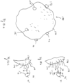
- the fiber-like structures 705 as shown in Figure 7e can be made of individual fibers 401, 401' as shown in Figure 8a-8c .
- the fiber 401 ( Figure 8a ) can be made of a polymer that has a plurality of molecules 73 to provide the functional group 78 and the attaching molecular segment 76.
- a xanthate for example, has both the functional group 78 and the molecular segment 76 to be incorporated into the polymer that is used to make the fiber 401.
- a functional group 78 is also known as a collector that is ionic or non-ionic to attract mineral particles 72.
- the ion can be anionic or cationic.
- An anion includes, but not limited to, oxyhydryl, such as carboxylic, sulfates and sulfonates, and sulfhydral, such as xanthates and dithiophosphates.
- Other molecules or compounds that can be used to provide the function group 78 include thionocarbamates, thioureas, xanthogens, monothiophosphates, hydroquinones and polyamines.
- the fiber 401 is coated with polymer that has the molecules 73 to provide the functional group 78 and the attaching molecular segment 76.
- the fiber 401 can be made of glass, ceramic, metal, nylon, cotton or a different polymer.
- a diagram of the fiber 401 and the attached molecules 73 is shown in Figure 8a .
- a synthetic material as defined in the claims is provided at least on the collection surfaces.
- the fiber 401' ( Figure 8b ) can be made of a polymer that has a plurality of molecules 79 to render the fiber 401' (and thus the collection areas 23, 123 and 223 of Figures 4, 5, 6 ) hydrophobic.
- the polymer can be a hydrophobic material such as polystyrene, poly(d,l-lactide), poly(dimethylsiloxane), polypropylene, polyacrylic, polyethylene, etc.
- the polymer can also be a hydrophobically-modified polymer, such as hydrophobically-modified ethyl hydroxyethyl cellulose.
- the fiber 401' can be made of glass, ceramic, metal, nylon, cotton or other fabric materials and coated with hydrophobic molecules, such as polysiloxanates, alkylsilane and fluoroalkylsilane.
- hydrophobic molecules such as polysiloxanates, alkylsilane and fluoroalkylsilane.
- a synthetic material as defined in the claims is provided at least on the collection surfaces.
- the molecules 79 cause the fiber 401' to become hydrophobic.
- a hydrophobically-modified mineral particle 72' can be attracted to the hydrophobic fiber 401'.
- the hydrophobically-modified, or wetted, mineral particle 72' comprises a mineral particle 71 and one or more molecules 73 attached thereon.
- the molecule 73, or collector has a functional group 78 attached to the mineral particle 71 and a hydrophobic chain or molecular segment 76.
- a diagram showing the attraction between the hydrophobic chain or molecular segments 76 and the hydrophobic fiber 401' is shown in Figure 8b .
- the particles 72' may be non-mineral (outside the scope of the claims) and can be some harmful particles in a body of water.
- the hydrophobic fiber 401' can also be used to attract non-mineral particles (outside the scope of the claims).
- a non-mineral particle 71' has one or more hydrophobic chains or molecular segments 76
- the non-mineral particle 71' is also attracted to the hydrophobic fiber 401'.
- a diagram showing the attraction between non-mineral particles 71' (outside the scope of the claims) and the hydrophobic fiber 401' is shown in Figure 8c .
- the hydrophobic fiber 401' can be used in a filter, impeller or conveyor belt (similar to those shown in Figures 4-6 ) for water-pollution control, water purification, etc. Such applications are outside the scope of the claims.
- the surfaces and edges around the openings or surface structures 701, 702, 703, 704 can be functionalized to provide the molecules 73 ( Figures 9a, 9b ).
- the exposed surfaces and edges around the openings or surface structures 701, 702, 703, 704 are represented by surface portions 403, 403' as shown in Figures 9a-9c .
- the length L of the surface portions 403, 403' can be equal to the thickness of the impeller 20, conveyor belt 120 and filter 220 ( Figures 4-6 ).
- the surface portion 403 can be made of a polymer that has a plurality of molecules 73 to provide the functional group 78 and the attaching molecular segment 76.
- the surface portion 403 is coated with polymer that has the molecules 73 to provide the functional group 78 and the attaching molecular segment 76.
- the surface portion 403 can be made of glass, ceramic, metal, nylon, cotton or a different polymer.
- the functional group 78 is used to attract mineral particles 72.
- a diagram of the surface portion 403 and the attached molecules 73 is shown in Figure 9a . It is, however, stressed, that at least on the collection surfaces a synthetic material as defined in the claims is provided.
- the surface portion 403' can be made of a polymer having a plurality of molecules 79 that render the surface portion 403' (and thus the collection areas 23, 123 and 223 of Figures 4, 5, 6 ) hydrophobic.
- the polymer can be a hydrophobic material such as polystyrene, poly(d,l-lactide), poly(dimethylsiloxane), polypropylene, polyacrylic, polyethylene, etc.
- the polymer can also be a hydrophobically-modified polymer, such as hydrophobically-modified ethyl hydroxyethyl cellulose.
- the surface portion 403' can be made of glass, ceramic, metal, nylon, cotton or other fabric materials and coated with hydrophobic molecules, such as polysiloxanates, alkylsilane and fluoroalkylsilane.
- hydrophobic molecules such as polysiloxanates, alkylsilane and fluoroalkylsilane.
- a synthetic material as defined in the claims is provided at least on the collection surfaces.
- the molecules 79 cause the surface portion 403' to become hydrophobic.
- a hydrophobically-modified mineral particle 72' is attracted to the hydrophobic surface portion 403'.
- Figure 9b A diagram showing the attraction between the molecular segments 76 and the hydrophobic surface portion 403' is shown in Figure 9b .
- the particles 72' may be non-mineral and can be some harmful particles in a body of water (outside the scope of the claims).
- the hydrophobic surface portion 403' can also be used to attract non-mineral particles (outside the scope of the claims). For example, if a non-mineral particle 71' has one or more hydrophobic chains or molecular segments 76, the non-mineral particle 71' is also attracted to the hydrophobic surface portion 403'.
- a diagram showing the attraction between the non-mineral particles 71' and the hydrophobic surface portion 403' is shown in Figure 9c .
- a filter, impeller or conveyor belt (similar to those shown in Figures 4-6 ) that has hydrophobic surface portions 403'can also be used for water-pollution control, water purification, etc. to rid of hydrophobically-modified particles 72' which may not be a mineral of interest, but some metal harmful to the environment, such applications being outside the scope of the claims.
- the treatment of plain surface 706 can be made similar to the surface portions 403, 403' as shown in Figures 9a-9c . That is, the plain surface 706 can be functionalized to provide a functional group 78 as shown in Figure 9a .
- the plain surface 706 can also be functionalized to be hydrophobic, as shown in Figures 9b and 9c , with a synthetic material as defined in the claims being provided at least on the collection surfaces.
- the pulp slurry 11 Figure 1a
- the pulp slurry 101 Figure 2
- the pulp slurry 201 Figure 3
- collector molecules such as xanthates
- the impeller 20 ( Figure 1a ), the conveyor belt 120 ( Figure 2 ) and the filter 220 ( Figure 3 ) are used in a horizontal pipeline for mineral separation.
- a group of filters 220 can be used in a first processor 202 as shown in Figure 3 .
- a plurality of filters 220 are placed into a horizontal pipeline 300 to collect the valuable material in the slurry 322, as shown in Figure 10a . As the slurry passes through the filters 220, some of the mineral particles in the slurry will become attached to collection area 223 and the openings (see Figures 7a-7e ).
- one or more of the filters 220 can be taken out of the horizontal pipeline 300 for mineral releasing (see Figure 10b ) while other filters 220 continue to collect the mineral particles.
- the tailings 342 can be discharged or transported to a tailings pond or the like (see Figure 11 ).
- the attached mineral particles on the filter 220 can be released in a release rich environment with a low pH solution and/or ultrasonic agitation.
- the pH value of the low pH solution can be 0 to 7, for example.
- the filter 220 with collected mineral particles can be placed in a releasing apparatus 410 to be washed with a mixture of acid and water provided by water container 424 and acid container 422.
- the filter 200 comprises a panel, such as a glass panel, a ceramic panel, a metal sheet, a plastic sheet, wherein the panel is coated with a synthetic material as defined in the claims, the synthetic material comprising a plurality of molecules configured to attract the mineral particles.
- the surface of the panel can be a plain surface as shown in Figure 7f .
- the reclaimed water 427 can be channeled back for reuse.
- the concentrated mineral 440 can be taken out of the releasing apparatus 410.
- the pH value is lower than the pH value for mineral attachment. It should be noted that, however, when the valuable material is copper, for example, it is possible to provide a lower pH environment for the attachment of mineral particles and to provide a higher pH environment for the releasing of the mineral particles from the synthetic beads or bubbles.
- the pH value is chosen to facilitate the strongest attachment, and a different pH value is chosen to facilitate release.
- one pH value may be chosen for mineral attachment, and a different pH value may be chosen for mineral releasing. The different pH could be higher or lower, depending on the specific mineral and collector.
- the invention is described in relation to mineral separation, including the separation of copper from ore.
- Tailings scavenger cells that are used to scavenge the unrecovered minerals from a tailings stream.
- Tailings cleaning cell that is used to clean unwanted material from the tailings stream before it is sent to the disposal pond.
- Tailings reclamation machine that is placed in the tailings pond to recover valuable mineral that has been sent to the tailings pond.
- the filter 220 can also be used for mineral recovery in a tailings pond.
- one or more filters 220 may be placed in a tailings pond 350 to collect the mineral particles in the tailings 342.
- collector molecules such as xanthates should be added into the tailings 342 so that the mineral particles in the tailings can be wetted.
- the collection surfaces on the surface structures are coated with a synthetic material as defined in the claims, the synthetic material having particular molecules to attract mineral particles.
- the synthetic material can be used to provide those particular molecules on beads or bubbles, or to make the beads or bubbles (see Figures 13a-14b ).
- the bubbles or beads that have the particular molecules to attract mineral particles are herein referred to as synthetic bubbles or beads.
- the synthetic beads or bubbles 170 are used in an impeller or a filter to collect mineral particles 72, 72' (see Figures 8a-9b , 13a-14b ).
- the impeller uses a cage or the like to contain a plurality of synthetic beads to provide the collection surfaces in the collection area 23.
- the filter uses a cage or the like to contain a plurality of synthetic beads 170 to provide the collection surfaces in the collection area 223.
- the synthetic beads or bubbles 170 are used to collect valuable material in a tailings pond 350 ( Figure 11 ), they can be put in a sack 320 as shown in Figure 12c .
- the synthetic material to be used on the synthetic beads or bubbles 170 is a synthetic material as defined in the claims and may have the functional groups 78 to attract the mineral particles 72, or may have the hydrophobic molecules 79.
- Figure 13a illustrates a synthetic bead functionalized to attract hydrophobic particles.
- the synthetic bubble or bead 170 has a solid-phase bead body to provide a bead surface 174.
- At least the outside part of the bead body is made of a synthetic material, such as a hydrophobic polymer, or a coating of a hydrophobic chemical.
- a synthetic material as defined in the claims is provided at least on the collection surfaces of the beads used in an impeller or a filter according to the present invention.
- the surface 174 of the synthetic bubble or bead comprises a plurality of molecules 79 which renders the surface 174 hydrophobic.
- the surface 174 may be a glass surface coated with polysiloxanates which can bind to the hydroxyl group of the glass surface.
- Polysiloxanates such as hydroxyl-terminated polydimethysiloxanes, have a silicon-oxygen chain to provide the hydrophobic molecules 79.
- the hydrophobic particle 72' as shown in Figure 13b , can be a mineral particle 71 having one or more collectors 73 attached thereto. One end (78) of the collector 73 has an ionizing bond attached to the mineral particle 71. The other end of the collector 73 has a hydrophobic chain 76 which tends to move into the hydrophobic molecules 79.
- the hydrophobic particle 72' can be a wetted mineral particle.
- a collector such as xanthate, has both the functional group 78 and the molecule 76.
- the hydrophobic particle 72 can be a particle 71' that has a hydrophobic chain 76.
- Such particle can be non-mineral related (outside the scope of the claims), but it can be arranged to contact with the hydrophobic synthetic bubbles or beads 170 of the present invention.
- the particle 71 may be non-mineral and can be harmful to the environment (outside the scope of the claims).
- the hydrophobic bubbles or beads 170 according to the present invention, can be used in non-mining applications, such as water-pollution control and water purification, such applications being outside the scope of the claims.
- the size of the synthetic bead can be smaller than the minimum size of the mineral particles which is about 150 ⁇ m, and can be larger than the maximum size of the mineral particles. In certain applications, the size of the synthetic bead can be 1cm or larger.
- Figure 14a illustrates a synthetic bead having a functional group to attract mineral particles.
- the synthetic bead 170 has a bead body to provide a bead surface 174 to attract mineral particles 72.
- Figure 14b is an enlarged surface of the synthetic bead functionalized to attract mineral particles.
- At least the outside part of the bead body is made of a synthetic material, such as polymer, so as to provide a plurality of molecules or molecular segments 76 on the surface 174.
- a synthetic material as defined in the claims is provided at least on the collection surfaces.
- the molecule 76 is used to attach a chemical functional group 78 to the surface 174.
- the molecule 76 can be a hydrocarbon chain, for example, and the functional group 78 can have an anionic bond for attracting a mineral, such as copper to the surface 174.
- a xanthate for example, has both the functional group 78 and the molecular segment 76 to be incorporated into the polymer that is used to make the synthetic bead 70.
- the functional group 78 is also known as a collector that can have a non-ionizing or ionizing bond to attract the mineral particles 72.
- a chelating agent can be incorporated into the polymer as a collector site for attracting a mineral, such as copper.
- the releasing of the mineral particles from the synthetic beads can be similar to the releasing of the mineral particles from the impeller, conveyor belt or the filter.
- the synthetic beads 170 in the collection area 23 or 223 or in the sack 320 ( Figures 12a-12c ) have collected a certain amount of mineral particles
- the synthetic beads 170 can be made contact with a low pH solution and/or subjected to ultrasonic agitation (e.g., Figure 10b ) in order to release the mineral particles.
- a high pH solution can also be used for releasing certain mineral particles while a low pH environment is used for mineral attachment.
- only a portion of the surface of the synthetic bead is functionalized to be hydrophobic. This has the benefits as follows:
- only a portion of the surface of the synthetic bead is functionalized with collectors. This also has the benefits of
- one part of the synthetic bead is functionalized with collectors while another part of same synthetic bead is functionalized to be hydrophobic as shown in Figures 15a and 15b .
- a synthetic bead 74 has a surface portion where polymer is functionalized to have collector molecules 73 with functional group 78 and molecular segment 76 attached to the surface of the bead 74.
- the synthetic bead 74 also has a different surface portion where polymer is functionalized to have hydrophobic molecules 79.
- the entire surface of the synthetic bead 74 can be functionalized to have collector molecules 73, but a portion of the surface is functionalized to have hydrophobic molecules 79 render it hydrophobic.
- This "hybrid" synthetic bead can collect mineral particles that are wet and not wet.
- the surface of a synthetic bead can be functionalized to have a collector molecule.
- the collector has a functional group with an ion capable of forming a chemical bond with a mineral particle.
- a mineral particle associated with one or more collector molecules is referred to as a wetted mineral particle.
- the synthetic bead can be functionalized to be hydrophobic in order to collect one or more wetted mineral particles.
Landscapes
- Chemical & Material Sciences (AREA)
- Engineering & Computer Science (AREA)
- Chemical Kinetics & Catalysis (AREA)
- Life Sciences & Earth Sciences (AREA)
- Organic Chemistry (AREA)
- Analytical Chemistry (AREA)
- Biotechnology (AREA)
- Water Supply & Treatment (AREA)
- Environmental & Geological Engineering (AREA)
- Hydrology & Water Resources (AREA)
- Manufacturing & Machinery (AREA)
- Materials Engineering (AREA)
- Mechanical Engineering (AREA)
- Metallurgy (AREA)
- Physical Or Chemical Processes And Apparatus (AREA)
- Separation Of Solids By Using Liquids Or Pneumatic Power (AREA)
- Separation, Recovery Or Treatment Of Waste Materials Containing Plastics (AREA)
- Filtering Materials (AREA)
- Separation Using Semi-Permeable Membranes (AREA)
- Compositions Of Macromolecular Compounds (AREA)
- Farming Of Fish And Shellfish (AREA)
- Solid-Sorbent Or Filter-Aiding Compositions (AREA)
- Physical Water Treatments (AREA)
- Glanulating (AREA)
- Water Treatment By Sorption (AREA)
- Adornments (AREA)
- Other Resins Obtained By Reactions Not Involving Carbon-To-Carbon Unsaturated Bonds (AREA)
- Cyclones (AREA)
- Medicines Containing Material From Animals Or Micro-Organisms (AREA)
- Processing And Handling Of Plastics And Other Materials For Molding In General (AREA)
- Management, Administration, Business Operations System, And Electronic Commerce (AREA)
- Separation Of Suspended Particles By Flocculating Agents (AREA)
- Paper (AREA)
- Water Treatment By Electricity Or Magnetism (AREA)
- Processing Of Solid Wastes (AREA)
Claims (15)
- Vorrichtung in Form eines Förderbands, eines Filters oder eines Flügelrads, umfassend:einen Sammelbereich zur Aufnahme eines funktionalisierten Polymers,wobei der Sammelbereich Sammelflächen umfasst, die dafür konfiguriert sind, mit einem Gemisch aus Wasser und Wertstoff in Kontakt zu kommen, wobei der Wertstoff eine Vielzahl von Mineralpartikeln umfasst; undein synthetisches Material, das zumindest auf den Sammelflächen vorgesehen ist, wobei das synthetische Material eine Vielzahl von Molekülen umfasst, die eine funktionelle Gruppe umfassen, die so gestaltet ist, dass sie die Mineralpartikel an die Sammeloberflächen anzieht, wobei die funktionelle Gruppe so gestaltet ist, dass sie die Sammelflächen hydrophob macht, und wobei das synthetische Material ein Siloxanderivat umfasst.
- Vorrichtung nach Anspruch 1, wobei die funktionelle Gruppe eine chemische funktionelle Gruppe zum Binden der Mineralpartikel an die Moleküle umfasst.
- Vorrichtung nach Anspruch 1, wobei die funktionelle Gruppe ein Ion umfasst, das entweder anionisch oder kationisch ist.
- Vorrichtung nach Anspruch 3, wobei die funktionelle Gruppe ein oder mehrere Ionen in Carbonsäuren, Sulfaten, Sulfonaten, Xanthaten, Dithiophosphaten, Thionocarbamaten, Thioharnstoffen, Xanthogenen, Monothiophosphaten, Hydrochinonen und Polyaminen umfasst.
- Vorrichtung nach Anspruch 1, wobei das Siloxanderivat Polydimethylsilan ist oder aus einer Gruppe ausgewählt ist, die aus hydrophob modifizierten Ethylhydroxyethylcellulosepolysiloxanaten besteht, oder wobei das Siloxanderivat Polysiloxanate oder hydroxyl-terminierte Polydimethylsiloxane umfasst.
- Vorrichtung nach Anspruch 1, wobei das Siloxanderivat aus einer Gruppe ausgewählt ist, die aus hydrophob modifizierten Ethylhydroxyethylcellulosepolysiloxanaten besteht, und wobei die Mineralpartikel ein oder mehrere daran gebundene hydrophobe Molekülsegmente umfassen.
- Vorrichtung nach Anspruch 1, wobei das Gemisch ferner eine Vielzahl von Sammlermolekülen umfasst und jedes der Sammlermoleküle ein hydrophobes Molekülsegment und eine ionisierende Bindung umfasst, die an das Mineralpartikel bindet.
- Vorrichtung nach Anspruch 1, wobei es sich bei der Vorrichtung um einen Filter oder ein Flügelrad handelt, wobei der Filter oder das Flügelrad einen Käfig verwendet, der eine Vielzahl von Kunststoffkügelchen enthält, um die Sammelflächen im Sammelbereich bereitzustellen.
- Vorrichtung nach Anspruch 1, wobei die Vorrichtung ein mit einem funktionalisierten Polymer beschichteter Sammelfilter ist, der die Form einer Membran hat.
- Verfahren, umfassend:Bereitstellen eines Sammelbereichs auf einem Förderband, einem Filter oder einem Flügelrad, wobei der Sammelbereich ein funktionalisiertes Polymer trägt und Sammelflächen umfasst, die dafür konfiguriert sind, mit einem Gemisch aus Wasser und Wertstoff in Kontakt zu kommen, wobei der Wertstoff eine Vielzahl von Mineralpartikeln umfasst; undBereitstellen eines synthetischen Materials, das zumindest auf den Sammelflächen vorgesehen ist, wobei das synthetische Material eine Vielzahl von Molekülen umfasst, die eine funktionelle Gruppe umfassen, die so gestaltet ist, dass sie die Mineralpartikel an die Sammelflächen anzieht, wobei die funktionelle Gruppe so gestaltet ist, dass sie die Sammelflächen hydrophob macht, und wobei das synthetische Material ein Siloxanderivat umfasst.
- Verfahren nach Anspruch 10, wobei die funktionelle Gruppe eine chemische Bindung zum Binden der Mineralpartikel an die Moleküle umfasst, wobei die chemische Bindung ein oder mehrere Ionen in Carbonsäuren, Sulfaten, Sulfonaten, Xanthaten, Dithiophosphaten, Thionocarbamaten, Thioharnstoffen, Xanthogenen, Monothiophosphaten, Hydrochinonen und Polyaminen umfasst.
- Verfahren nach Anspruch 10, wobei das Siloxanderivat Polydimethylsilan ist oder wobei das Siloxanderivat aus einer Gruppe ausgewählt ist, die aus hydrophob modifizierten Ethylhydroxyethylcellulosepolysiloxanaten besteht, oder Polysiloxanate oder hydroxyl-terminierte Polydimethylsiloxane umfasst.
- Verfahren nach Anspruch 10, wobei die Mineralpartikel ein oder mehrere daran gebundene hydrophobe Molekülsegmente umfassen.
- Verfahren nach Anspruch 10, wobei der Sammelbereich auf einem Filter oder einem Flügelrad vorgesehen ist, wobei der Filter oder das Flügelrad einen Käfig verwendet, der eine Vielzahl von Kunststoffkügelchen enthält, um die Sammelflächen im Sammelbereich bereitzustellen.
- Verfahren nach Anspruch 10, wobei der Sammelbereich auf einem mit einem funktionalisierten Polymer beschichteten Sammelfilter vorgesehen ist, der die Form einer Membran hat.
Applications Claiming Priority (3)
| Application Number | Priority Date | Filing Date | Title |
|---|---|---|---|
| US201161489893P | 2011-05-25 | 2011-05-25 | |
| US201161533544P | 2011-09-12 | 2011-09-12 | |
| PCT/US2012/039631 WO2012162632A1 (en) | 2011-05-25 | 2012-05-25 | Mineral separation using functionalized filters and membranes |
Publications (4)
| Publication Number | Publication Date |
|---|---|
| EP2714248A1 EP2714248A1 (de) | 2014-04-09 |
| EP2714248A4 EP2714248A4 (de) | 2015-04-22 |
| EP2714248B1 true EP2714248B1 (de) | 2024-08-28 |
| EP2714248C0 EP2714248C0 (de) | 2024-08-28 |
Family
ID=47217769
Family Applications (9)
| Application Number | Title | Priority Date | Filing Date |
|---|---|---|---|
| EP12849247.7A Active EP2714233B1 (de) | 2011-05-25 | 2012-05-25 | Synthetischer kügelchen in einer flusszelle oder säule |
| EP12789209.9A Active EP2715055B1 (de) | 2011-05-25 | 2012-05-25 | Mineraltrennung mit polymerblasen oder -kügelchen auf grössen-, gewichts- oder magnetbasis |
| EP12788889.9A Active EP2714596B1 (de) | 2011-05-25 | 2012-05-25 | Verfahren und vorrichtung zur freisetzung von mineralien aus synthetischen kügelchen |
| EP12792251.6A Active EP2714242B1 (de) | 2011-05-25 | 2012-05-25 | Flotationstrennung mit perlen oder blasen die polydimethylsiloxan enthalten |
| EP12849063.8A Active EP2714949B1 (de) | 2011-05-25 | 2012-05-25 | Mineralgewinnung aus bruchmaterialien mithilfe von hydroxyterminierten polydimethylsiloxanen |
| EP12789960.7A Active EP2714248B1 (de) | 2011-05-25 | 2012-05-25 | Mineralienabscheidung |
| EP12788746.1A Active EP2717988B1 (de) | 2011-05-25 | 2012-05-25 | Synthetische kugeln mit wasserabweisender oberfläche |
| EP12789071.3A Active EP2714792B1 (de) | 2011-05-25 | 2012-05-25 | Mit molekülen funktionalisierte synthetische kügelchen zum anziehen von und anhaften an mineralpartikeln von interesse |
| EP12790002.5A Active EP2714235B1 (de) | 2011-05-25 | 2012-05-25 | Mineraltrennung mittels eines funktionalisierten polymerbeschichteten teils |
Family Applications Before (5)
| Application Number | Title | Priority Date | Filing Date |
|---|---|---|---|
| EP12849247.7A Active EP2714233B1 (de) | 2011-05-25 | 2012-05-25 | Synthetischer kügelchen in einer flusszelle oder säule |
| EP12789209.9A Active EP2715055B1 (de) | 2011-05-25 | 2012-05-25 | Mineraltrennung mit polymerblasen oder -kügelchen auf grössen-, gewichts- oder magnetbasis |
| EP12788889.9A Active EP2714596B1 (de) | 2011-05-25 | 2012-05-25 | Verfahren und vorrichtung zur freisetzung von mineralien aus synthetischen kügelchen |
| EP12792251.6A Active EP2714242B1 (de) | 2011-05-25 | 2012-05-25 | Flotationstrennung mit perlen oder blasen die polydimethylsiloxan enthalten |
| EP12849063.8A Active EP2714949B1 (de) | 2011-05-25 | 2012-05-25 | Mineralgewinnung aus bruchmaterialien mithilfe von hydroxyterminierten polydimethylsiloxanen |
Family Applications After (3)
| Application Number | Title | Priority Date | Filing Date |
|---|---|---|---|
| EP12788746.1A Active EP2717988B1 (de) | 2011-05-25 | 2012-05-25 | Synthetische kugeln mit wasserabweisender oberfläche |
| EP12789071.3A Active EP2714792B1 (de) | 2011-05-25 | 2012-05-25 | Mit molekülen funktionalisierte synthetische kügelchen zum anziehen von und anhaften an mineralpartikeln von interesse |
| EP12790002.5A Active EP2714235B1 (de) | 2011-05-25 | 2012-05-25 | Mineraltrennung mittels eines funktionalisierten polymerbeschichteten teils |
Country Status (14)
| Country | Link |
|---|---|
| US (11) | US9827574B2 (de) |
| EP (9) | EP2714233B1 (de) |
| CN (4) | CN104010708B (de) |
| AU (9) | AU2012258615B2 (de) |
| CA (9) | CA2836129C (de) |
| CL (9) | CL2013003379A1 (de) |
| DK (2) | DK2714596T3 (de) |
| ES (3) | ES2908077T3 (de) |
| PE (9) | PE20142002A1 (de) |
| PL (3) | PL2714242T3 (de) |
| RS (1) | RS63788B1 (de) |
| RU (3) | RU2600764C2 (de) |
| WO (9) | WO2012162593A2 (de) |
| ZA (9) | ZA201309607B (de) |
Families Citing this family (62)
| Publication number | Priority date | Publication date | Assignee | Title |
|---|---|---|---|---|
| PE20142002A1 (es) | 2011-05-25 | 2014-12-21 | Cidra Corporate Services Inc | Tecnicas para transportar perlas o burbujas sinteticas en una celda o columna de flotacion |
| US10835905B2 (en) | 2011-05-25 | 2020-11-17 | Cidra Corporate Services Inc. | Recovery media for mineral processing |
| US12186690B2 (en) | 2011-05-25 | 2025-01-07 | Cidra Corporate Services Inc. | Polymer coating for selective separation of hydrophobic particles in aqueous slurry |
| US9731221B2 (en) | 2011-05-25 | 2017-08-15 | Cidra Corporate Services, Inc. | Apparatus having polymer surfaces having a siloxane functional group |
| WO2013112240A1 (en) * | 2011-12-13 | 2013-08-01 | Cidra Corporate Services Inc. | Mineral separation using functionalized polymer or polymer-coated filters and membranes |
| WO2013130794A1 (en) * | 2012-02-28 | 2013-09-06 | Cidra Corporate Services Inc. | Method and system for floation separation in a magnetically controllable and steerable medium |
| US10751693B2 (en) | 2012-05-22 | 2020-08-25 | CiDRA Corporate Service Inc. | Mineral recovery using hydrophobic polymer surfaces |
| CA2897502C (en) | 2013-01-08 | 2021-07-20 | Cidra Corporate Services Inc. | Smart proppant technology for fracking and well production performance monitoring |
| EP2943714A4 (de) | 2013-01-09 | 2016-08-17 | Cidra Corporate Services Inc | Intelligentes rohrkonzept auf basis eines eingebetteten taggant-sensors und/oder farbcodierter elemente zur überwachung eines auskleidungsverschleisses in ausgekleideten rohrleitungen einschliesslich mit urethan ausgekleideter rohrleitungen |
| AU2014265626A1 (en) * | 2013-05-13 | 2015-11-26 | Cidra Corporate Services Inc. | Polymer surfaces having a siloxane functional group |
| WO2015095054A2 (en) * | 2013-12-17 | 2015-06-25 | Flsmidth A/S | Process for flotation leaching copper sulfide minerals |
| DE102014200415A1 (de) | 2013-12-20 | 2015-06-25 | Siemens Aktiengesellschaft | Verfahren zur Abtrennung einer definierten mineralischen Wertstoffphase aus einem gemahlenen Erz |
| US10772997B2 (en) * | 2014-05-15 | 2020-09-15 | Ronald D. Shippert | Tissue parcelization method and apparatus |
| PE20170282A1 (es) * | 2014-05-30 | 2017-04-12 | Cidra Corporate Services Inc | Recuperacion de minerales usando superficies polimericas hidrofobicas |
| US10481696B2 (en) | 2015-03-03 | 2019-11-19 | Nvidia Corporation | Radar based user interface |
| CN104815760B (zh) * | 2015-03-24 | 2017-08-29 | 湖南有色金属研究院 | 一种用于含磁性杂质的氧化铜矿浮选工艺的捕收剂 |
| CN104888959B (zh) * | 2015-04-30 | 2017-06-23 | 中国地质科学院矿产综合利用研究所 | 一种强磁性矿物的提质降杂选矿方法 |
| WO2017066756A1 (en) | 2015-10-16 | 2017-04-20 | Cidra Corporate Services Inc. | Opportunities for recovery augmentation process as applied to molybdenum production |
| US10981181B2 (en) | 2015-10-16 | 2021-04-20 | Cidra Corporate Services Inc. | Mineral beneficiation utilizing engineered materials for mineral separation and coarse particle recovery |
| US11517918B2 (en) * | 2015-11-16 | 2022-12-06 | Cidra Corporate Services Llc | Utilizing engineered media for recovery of minerals in tailings stream at the end of a flotation separation process |
| EP3181230A1 (de) * | 2015-12-17 | 2017-06-21 | Basf Se | Ultraflotation mit magnetisch ansprechbaren trägerpartikeln |
| EP3397787B1 (de) * | 2015-12-28 | 2026-02-18 | Cidra Corporate Services LLC | Trommelzelle für mineralienrückgewinnung mithilfe von technisierten medien |
| CN120535056A (zh) * | 2016-01-07 | 2025-08-26 | 锡德拉企业服务有限责任公司 | 用于水系统中的矿物颗粒的选择性分离的、开孔或网状泡沫的官能化开放网络结构 |
| US10416049B2 (en) * | 2016-04-05 | 2019-09-17 | The Government Of The United States Of America, As Represented By The Secretary Of The Navy | Processing of solid micron sized particles for rapid deposition on substrate surfaces with uniform particle distribution |
| AU2017339973B2 (en) | 2016-10-04 | 2021-03-18 | Cidra Corporate Services Llc. | Hybrid - flotation recovery of mineral bearing ores |
| PE20190703A1 (es) * | 2016-10-04 | 2019-05-15 | Cidra Corporate Services Llc | Tecnica de modificacion de la distribucion del tamano de clasificacion de particulas basada en medios hidrofobos para mejorar la separacion por flotacion en lecho fluidizado |
| MX2019003881A (es) * | 2016-10-04 | 2019-09-18 | Cidra Corporate Services Llc | Separación de sulfuros de cobre y molibdeno a partir de pirita usando un proceso híbrido de agua de mar/agua desalinizada. |
| US11241700B2 (en) | 2016-10-07 | 2022-02-08 | Cidra Corporate Services, Inc. | Non-flotation based recovery of mineral bearing ore using hydrophobic particle collection in a pipeline section |
| WO2018085364A1 (en) | 2016-11-01 | 2018-05-11 | Cidra Corporate Services, Inc | Reactor system for separation and enrichment of minerals from a slurry containing minerals and other materials |
| EP3535038A4 (de) | 2016-11-02 | 2020-07-01 | Cidra Corporate Services LLC | Polymerbeschichtung zur selektiven trennung von hydrophoben teilchen in einer wässrigen suspension |
| CL2016003331A1 (es) * | 2016-12-26 | 2017-05-05 | Univ Chile | Celda de flotación magneto-centrifuga para concentración de minerales que reduce el consumo de agua |
| MX2019010201A (es) | 2017-02-28 | 2019-12-19 | Cidra Corporate Services Llc | Roceso para recubrir espumas reticuladas. |
| WO2018160648A1 (en) * | 2017-02-28 | 2018-09-07 | Cidra Corporate Services Llc | High intensity conditioning prior to enhanced mineral separation process |
| PE20191341A1 (es) | 2017-02-28 | 2019-09-30 | Cidra Corporate Services Llc | Configuraciones de proceso para evitar el exceso de triturado de concentrados de barrido |
| US20200030819A1 (en) * | 2017-03-01 | 2020-01-30 | Cidra Corporate Services Llc | Polymer coating for selective separation of hydrophobic particles in aqueous slurry |
| AU2018227538B2 (en) * | 2017-03-01 | 2022-07-14 | Cidra Corporate Services Llc | Mineral processing plant |
| EP3589764A4 (de) * | 2017-03-01 | 2021-01-13 | Cidra Corporate Services LLC | Zyklonunterlauf-scavengingverfahren unter verwendung von verbesserten mineraltrennkreisen (emsc) |
| EP3600590B1 (de) * | 2017-03-27 | 2025-10-01 | Cidra Corporate Services LLC | Entfernung hydrophober teilchen unter verwendung von kohlendioxid |
| DE102017111515A1 (de) | 2017-05-26 | 2018-11-29 | Gebrüder Dorfner GmbH & Co. Kaolin- und Kristallquarzsand-Werke KG | Composit-Partikel mit hydrophilen und hydrophoben Oberflächenbeschichtungen |
| CN107561146A (zh) * | 2017-08-15 | 2018-01-09 | 江西理工大学 | 一种更贴近真实矿物浮选的电化学研究方法 |
| CN111357045B (zh) * | 2017-11-16 | 2022-03-29 | 辛纳普蒂克斯公司 | 用于显示面板的多伽玛控制技术 |
| CA3090763A1 (en) | 2018-02-07 | 2019-08-15 | Cidra Corporate Services Llc | Open cell or reticulated foam having 3-dimensional open-network structure made of a hydrophobic material for selective separation of mineral particles |
| KR102700576B1 (ko) * | 2018-04-04 | 2024-08-30 | 조디 지 로빈스 | 비중에 의한 미네랄의 분리 |
| JP6642616B2 (ja) * | 2018-04-23 | 2020-02-05 | 栗田工業株式会社 | 湿式塗装ブース循環水の処理方法 |
| JP7102267B2 (ja) * | 2018-07-10 | 2022-07-19 | リンテック株式会社 | セラミックグリーンシート製造工程用剥離フィルム |
| CN109046743B (zh) * | 2018-07-20 | 2020-06-16 | 太原理工大学 | 一种用于磁铁矿分选的复合力场分选机及其分选方法 |
| CN109127110A (zh) * | 2018-08-10 | 2019-01-04 | 江苏凯达石英股份有限公司 | 黄铁矿型石英砂浮选提纯工艺 |
| EP3843902B1 (de) * | 2018-08-31 | 2026-01-21 | GT of Ohio, Ltd | Verfahren und vorrichtung zur kontinuierlichen magnetischen filtration von eisenhaltigem abbrand aus flüssigen lösungen |
| CN109110967B (zh) * | 2018-09-11 | 2021-09-10 | 博天环境集团股份有限公司 | 一种基于膜化学反应器的铝土矿选矿废水回用系统及方法 |
| CN109225657B (zh) * | 2018-09-25 | 2020-10-20 | 北矿机电科技有限责任公司 | 一种高浓度浮选机成套装置 |
| CN109482333B (zh) * | 2018-11-22 | 2020-02-14 | 中国矿业大学 | 一种铜矿石干-湿法联合富集工艺 |
| CN109731696B (zh) * | 2019-03-14 | 2019-12-13 | 中国矿业大学 | 一种适于粗颗粒回收的静态浮选方法 |
| CN109772591A (zh) * | 2019-03-22 | 2019-05-21 | 山东超美清洁能源有限公司 | 一种节能环保、清洁高效的助选剂 |
| KR102484008B1 (ko) * | 2021-02-23 | 2023-01-03 | 한국원자력연구원 | 부유선별에 의하여 오염물질이 흡착된 미세토를 오염 토양으로부터 분리하는 방법 및 상기 방법에 이용되는 소수성 무기 나노입자 |
| US20230149945A1 (en) * | 2021-11-17 | 2023-05-18 | Royal Biotech Inc | Method and System for Facilitating Green Screening, Classification, and Adsorption of Target Elements from a Mixture |
| AU2023347541A1 (en) | 2022-09-22 | 2025-04-03 | Cidra Corporate Services Llc | Novel promoters for mineral collection |
| WO2024112811A2 (en) | 2022-11-23 | 2024-05-30 | Good Earth Ip Holdings, Llc | Separation of minerals by gas injection |
| AU2024228498A1 (en) | 2023-02-28 | 2025-08-28 | Cidra Corporate Services Llc | Method for recovering and upgrading low concentration surfactants from wash water |
| CN116272436A (zh) * | 2023-04-11 | 2023-06-23 | 东北大学秦皇岛分校 | 一种铁尾矿基电纺纤维膜及其制备方法和应用 |
| CL2023003860A1 (es) * | 2023-12-21 | 2024-03-22 | Univ Concepcion | Reactor para mejorar la recuperación de elementos de valor por flotación y proceso de operación |
| WO2025195934A1 (en) * | 2024-03-18 | 2025-09-25 | Magnify Biotechnologies Gmbh | Utilizing magnetic separation process technology to capture target compounds |
| US20250339794A1 (en) | 2024-05-06 | 2025-11-06 | Active Minerals International, Llc | Product for mine tailings |
Citations (3)
| Publication number | Priority date | Publication date | Assignee | Title |
|---|---|---|---|---|
| EP0164237A2 (de) * | 1984-05-30 | 1985-12-11 | Dow Corning Corporation | Polyorganosiloxansammler zur Aufbereitung von Feinkohle durch Schaumflotation |
| US20100200510A1 (en) * | 2007-07-17 | 2010-08-12 | Basf Se | Process for the beneficiation of ores by means of hydrophobic surfaces |
| WO2012028701A2 (de) * | 2010-09-03 | 2012-03-08 | Basf Se | Hydrophobe, funktionalisierte partikel |
Family Cites Families (146)
| Publication number | Priority date | Publication date | Assignee | Title |
|---|---|---|---|---|
| US2588976A (en) | 1952-03-11 | Filter | ||
| US1684536A (en) | 1927-01-24 | 1928-09-18 | Guggenheim Brothers | Flotation process |
| US2585473A (en) | 1947-05-03 | 1952-02-12 | Vera Alward Kennedy | Extraction apparatus and method |
| US2678132A (en) | 1950-03-31 | 1954-05-11 | Socony Vacuum Oil Co Inc | Endless belt adsorption |
| US2699872A (en) | 1952-07-10 | 1955-01-18 | William H Kelsey | Pulp-circulating vacuum filter |
| US2934208A (en) | 1958-02-27 | 1960-04-26 | Saskatchewan Potash | Silicone reagent flotation |
| US2957576A (en) * | 1958-03-07 | 1960-10-25 | Anaconda Co | Recovery of molybdenite by flotation |
| SU118472A1 (ru) * | 1958-05-12 | 1958-11-30 | Р.Н. Беловод | Способ получени пиритных концентратов из хвостов медной и цинковой флотации |
| US3224582A (en) | 1965-06-01 | 1965-12-21 | Huber Corp J M | Kaolin clay beneficiation |
| GB1352515A (en) * | 1970-04-15 | 1974-05-08 | English Clays Lovering Pochin | Separation of particulate materials |
| US4100242A (en) * | 1971-02-24 | 1978-07-11 | Leach Irby H | Method of molding aqueous settable slurries containing shredded open-cell polystyrene particles |
| IT947165B (it) * | 1971-05-17 | 1973-05-21 | Grefco | Composizioni e processo per la eliminazione selettiva di prodot ti oleosi dall acqua |
| SU441314A1 (ru) | 1971-05-20 | 1974-08-30 | Предприятие П/Я М-5885 | Способ извлечени меди из кислых медьсодержащих растворов и пульп сорбцией |
| GB1339337A (en) | 1971-11-30 | 1973-12-05 | Engelhard Min & Chem | Method for treating floated solids |
| US3796308A (en) | 1972-07-24 | 1974-03-12 | Canadian Patents Dev | Bacterial oxidation in upgrading sulfidic ores and coals |
| US3970518A (en) | 1975-07-01 | 1976-07-20 | General Electric Company | Magnetic separation of biological particles |
| CA1085760A (en) | 1976-02-10 | 1980-09-16 | Research Council Of Alberta (The) | Process for recovering bitumen from tar sand |
| US4279756A (en) * | 1976-05-03 | 1981-07-21 | Commonwealth Scientific And Industrial Research Organization | Water clarification |
| GB1582956A (en) | 1976-07-30 | 1981-01-21 | Ici Ltd | Composite magnetic particles |
| USRE30360E (en) | 1977-12-14 | 1980-08-05 | Maryland Patent Development Co., Inc. | Magnetic separation of particulate mixtures |
| US4685963A (en) | 1978-05-22 | 1987-08-11 | Texasgulf Minerals And Metals, Inc. | Process for the extraction of platinum group metals |
| US4235562A (en) | 1978-12-08 | 1980-11-25 | Ribas Alberto L | Land reclamation system |
| US4224138A (en) | 1979-05-10 | 1980-09-23 | Jan Kruyer | Process for recovering bitumen from oil sand |
| US4269699A (en) | 1979-10-23 | 1981-05-26 | Canadian Patents & Dev. Ltd. | Bioadsorption alteration of iron sulfide surfaces |
| US4304573A (en) | 1980-01-22 | 1981-12-08 | Gulf & Western Industries, Inc. | Process of beneficiating coal and product |
| US4391608A (en) | 1980-03-31 | 1983-07-05 | Dondelewski Michael A | Process for the beneficiation of carbonous materials with the aid of ultrasound |
| DE3020211A1 (de) * | 1980-05-28 | 1981-12-03 | Krauss-Maffei AG, 8000 München | Verfahren zum entwaessern von in suspensionen enthaltenen farbstoffen |
| US4313832A (en) | 1980-06-12 | 1982-02-02 | Rohm And Haas Company | Method for treatment of aqueous solutions with ion exchange fibers |
| DE3030956A1 (de) * | 1980-08-16 | 1982-03-25 | Chemische Fabrik Pfersee Gmbh, 8900 Augsburg | Verfahren zur verbesserung des oelaufsaugevermoegens von torf, nach dem verfahren behandelter torf und dessen verwendung |
| SU1309904A3 (ru) | 1981-05-13 | 1987-05-07 | Берол Кеми Аб (Фирма) | Способ пенной флотации апатит-карбонатной руды |
| US4657666A (en) | 1981-10-26 | 1987-04-14 | W.S.R. Pty. Ltd. | Magnetic flotation |
| US4523991A (en) * | 1982-12-27 | 1985-06-18 | The Dow Chemical Company | Carrier particle for the froth flotation of fine ores |
| US4537599A (en) | 1983-04-28 | 1985-08-27 | Greenwald Sr Edward H | Process for removing sulfur and ash from coal |
| GB8314138D0 (en) | 1983-05-21 | 1983-06-29 | British Petroleum Co Plc | Benefication of carbonaceous fuels |
| US4511461A (en) | 1983-07-06 | 1985-04-16 | Jan Kruyer | Process for recovering minerals and metals by oleophilic adhesion |
| US4526680A (en) | 1984-05-30 | 1985-07-02 | Dow Corning Corporation | Silicone glycol collectors in the beneficiation of fine coal by froth flotation |
| US4556482A (en) | 1984-08-17 | 1985-12-03 | American Cyanamid Company | Process for the flotation of base metal sulfide minerals in acid, neutral or mildly alkaline circuits |
| GB8726857D0 (en) | 1987-11-17 | 1987-12-23 | Fospur Ltd | Froth floatation of mineral fines |
| US4981582A (en) | 1988-01-27 | 1991-01-01 | Virginia Tech Intellectual Properties, Inc. | Process and apparatus for separating fine particles by microbubble flotation together with a process and apparatus for generation of microbubbles |
| US5167798A (en) | 1988-01-27 | 1992-12-01 | Virginia Tech Intellectual Properties, Inc. | Apparatus and process for the separation of hydrophobic and hydrophilic particles using microbubble column flotation together with a process and apparatus for generation of microbubbles |
| SU1558473A2 (ru) * | 1988-03-21 | 1990-04-23 | Донецкий политехнический институт | Способ обогащени и обвоживани угл "ОВЗУМС |
| US4888106A (en) | 1988-04-18 | 1989-12-19 | American Cyanamid Company | Method of using polymeric sulfide mineral depressants |
| FI79953C (fi) | 1988-04-28 | 1990-04-10 | Svi Distec Oy | Apparatur foer flotationsanrikning. |
| DE3821465A1 (de) | 1988-06-25 | 1989-12-28 | Degussa | Verfahren zur herstellung ein- oder mehrfach substituierter organyloxysilylfunktioneller thioharnstoffe und diese verbindungen |
| US4971685A (en) | 1989-04-11 | 1990-11-20 | The United States Of America As Represented By The Secretary Of The Interior | Bubble injected hydrocyclone flotation cell |
| US5161694A (en) | 1990-04-24 | 1992-11-10 | Virginia Tech Intellectual Properties, Inc. | Method for separating fine particles by selective hydrophobic coagulation |
| WO1992011091A1 (en) | 1990-12-17 | 1992-07-09 | The Dow Chemical Company | Aryl monosulfonate collectors useful in the flotation of minerals |
| RU2022656C1 (ru) * | 1990-12-29 | 1994-11-15 | Акционерное общество "Союзцветметавтоматика" (научно-производственный комплекс "Югцветметавтоматика") | Устройство для определения расхода флотационных реагентов в рудной пульпе |
| RU2038155C1 (ru) * | 1991-07-04 | 1995-06-27 | Грозненский нефтяной научно-исследовательский институт | Липкий состав для извлечения алмазов |
| US5192423A (en) | 1992-01-06 | 1993-03-09 | Hydro Processing & Mining Ltd. | Apparatus and method for separation of wet particles |
| US5256298A (en) * | 1992-04-22 | 1993-10-26 | Powell Paul E | Continuous-belt separator/reactor and method |
| US5260353A (en) * | 1992-10-16 | 1993-11-09 | Kerr-Mcgee Chemical Corporation | Hydrophobicity through metal ion activation |
| GB2281521B (en) * | 1993-09-06 | 1997-04-09 | Supaflo Tech Pty Ltd | Membrane washing apparatus for flotation device |
| RU2063813C1 (ru) | 1993-12-10 | 1996-07-20 | Михаил Николаевич Злобин | Способ извлечения из руд алмазов |
| US5514218A (en) * | 1994-10-03 | 1996-05-07 | General Electric Company | Soil washing process using polymeric sorbents |
| RU2091141C1 (ru) | 1995-01-30 | 1997-09-27 | Российский научный центр "Прикладная химия" | Способ мембранного выделения фтористого водорода |
| US5670056A (en) | 1995-04-17 | 1997-09-23 | Virginia Tech Intellectual Properties, Inc. | Chemical-mechanical dewatering process |
| WO1996040438A1 (en) * | 1995-06-07 | 1996-12-19 | Cytec Technology Corp. | Method of depressing non-sulfide silicate gangue minerals |
| WO1997005085A1 (en) | 1995-07-28 | 1997-02-13 | E.I. Du Pont De Nemours And Company | Water-buoyant particulate materials containing micronutrients for phytoplankton |
| US5603841A (en) | 1995-10-31 | 1997-02-18 | Nalco Chemical Company | Hydrophobically-modified polymers for dewatering in mining processes |
| US5746910A (en) * | 1996-03-05 | 1998-05-05 | Her Majesty The Queen In Right Of Canada, As Represented By The Minister Of Natural Resources | Frothless flotation apparatus |
| CA2286805C (en) | 1997-04-15 | 2005-11-08 | Hideyuki Nishizawa | Solid-liquid countercurrent extraction continuously separating apparatus |
| IL139034A0 (en) | 1998-04-28 | 2001-11-25 | Nycomed Imaging As | Improvements in or relating to separation processes |
| FI104486B (fi) | 1998-10-14 | 2000-02-15 | Raimo Maeaettae | Menetelmä ja järjestelmä jäteveden puhdistamiseksi |
| US7759123B2 (en) | 1998-11-13 | 2010-07-20 | Mesosystems Technology, Inc. | Removing surface deposits of concentrated collected particles |
| US6200377B1 (en) * | 1999-04-16 | 2001-03-13 | Thiele Kaolin Company | Process for beneficiation of mixtures of mineral particles |
| AUPP991799A0 (en) * | 1999-04-23 | 1999-05-20 | Cardiac Crc Nominees Pty Limited | Siloxane-containing polyurethane-urea compositions |
| US6234318B1 (en) | 1999-05-04 | 2001-05-22 | Barrick Gold Corporation | Flotation and cyanidation process control |
| US6855260B1 (en) | 1999-06-07 | 2005-02-15 | Roe-Hoan Yoon | Methods of enhancing fine particle dewatering |
| ZA200006996B (en) | 1999-12-06 | 2001-05-29 | Antonio T Robles | Method for the regenaration of sorbent materials. |
| US6890431B1 (en) * | 2000-02-18 | 2005-05-10 | The F. B. Leopold Co., Inc. | Buoyant media flotation |
| DE60141204D1 (de) | 2000-04-01 | 2010-03-18 | Qinetiq Ltd | Polymeren, Verfahren, Zusammensetzungen, Klebstoffe, Verwendungen, Produkte |
| US6799682B1 (en) | 2000-05-16 | 2004-10-05 | Roe-Hoan Yoon | Method of increasing flotation rate |
| DE10042190A1 (de) | 2000-08-28 | 2002-03-14 | Messo Chemietechnik Gmbh | Verfahren zur Reinigung von Kristallen |
| US20020195376A1 (en) * | 2000-09-11 | 2002-12-26 | Siess Harold Edward | Method for the separation of a mixture of differing particulate types |
| US6576590B2 (en) | 2001-02-01 | 2003-06-10 | University Of Monatan | Materials for the separation of copper ions and ferric iron in liquid solutions |
| AUPR319001A0 (en) | 2001-02-19 | 2001-03-15 | Ausmelt Limited | Improvements in or relating to flotation |
| CN1463291A (zh) * | 2001-04-19 | 2003-12-24 | 赛弗根生物系统股份有限公司 | 用质谱法和亲和标记物鉴定生物分子的特性 |
| US7255793B2 (en) * | 2001-05-30 | 2007-08-14 | Cort Steven L | Methods for removing heavy metals from water using chemical precipitation and field separation methods |
| US7571814B2 (en) * | 2002-02-22 | 2009-08-11 | Wave Separation Technologies Llc | Method for separating metal values by exposing to microwave/millimeter wave energy |
| US7074337B2 (en) | 2002-08-12 | 2006-07-11 | Jeffrey S. Melcher | Methods and apparatuses for filtering water |
| US7264728B2 (en) * | 2002-10-01 | 2007-09-04 | Dow Corning Corporation | Method of separating components in a sample using silane-treated silica filter media |
| US6793079B2 (en) | 2002-11-27 | 2004-09-21 | University Of Illinois | Method and apparatus for froth flotation |
| FR2849444B1 (fr) * | 2002-12-30 | 2006-07-28 | Rhodia Chimie Sa | Procede de preparation d'un suspension de silice dans une matiere silicone eventuellement reticulable |
| FR2849842B1 (fr) | 2003-01-13 | 2006-03-03 | Rene Brunone | Bande de convoyage, convoyeur a bande la comportant et utilisation de la bande |
| WO2004064997A1 (en) | 2003-01-23 | 2004-08-05 | Inotech Ag | New microcapsules useful as extraction means in particular for extracting water or soil contaminants |
| US7641863B2 (en) | 2003-03-06 | 2010-01-05 | Ut-Battelle Llc | Nanoengineered membranes for controlled transport |
| AU2003901734A0 (en) | 2003-04-11 | 2003-05-01 | Unisearch Limited | Transparent superhydrophobic coating |
| US7344783B2 (en) * | 2003-07-09 | 2008-03-18 | Shell Oil Company | Durable hydrophobic surface coatings using silicone resins |
| US7270745B2 (en) | 2003-08-04 | 2007-09-18 | Schwartzkopf Steven H | Liquid filtration apparatus embodying super-buoyant filtration particles |
| DE10357063B3 (de) | 2003-12-04 | 2005-04-21 | Heraeus Tenevo Ag | Vertikalziehverfahren zur Herstellung eines zylinderförmigen Glaskörpers und Vorrichtung zur Durchführung des Verfahrens |
| EP1544596B1 (de) | 2003-12-17 | 2016-11-23 | Boehringer Ingelheim microParts GmbH | Verfahren und Vorrichtung zur Bestimmung der Viskosität |
| US7727710B2 (en) | 2003-12-24 | 2010-06-01 | 3M Innovative Properties Company | Materials, methods, and kits for reducing nonspecific binding of molecules to a surface |
| JP4211059B2 (ja) * | 2004-01-09 | 2009-01-21 | マックス株式会社 | 鉄筋結束機、ワイヤリール及びワイヤリールの識別方法 |
| US7426852B1 (en) | 2004-04-26 | 2008-09-23 | Expro Meters, Inc. | Submersible meter for measuring a parameter of gas hold-up of a fluid |
| US7267232B2 (en) | 2004-04-30 | 2007-09-11 | The Board Of Trustees Of The University Of Illinois | Flotation device and method of froth flotation |
| US7285219B2 (en) | 2004-08-10 | 2007-10-23 | Prime Separations, Inc. | Chromatographic separation member and method |
| CN101445568B (zh) * | 2004-10-26 | 2014-11-19 | 株式会社普利司通 | 具有连接基团的官能化聚合物 |
| US20090061226A1 (en) | 2004-12-07 | 2009-03-05 | Yissum Research Development Company Of The Hebrew | Spherical composites entrapping nanoparticles, processes of preparing same and uses thereof |
| CN101137443B (zh) * | 2004-12-23 | 2016-03-16 | 佐治亚-太平洋化学有限责任公司 | 从含粘土矿中提纯粘土的方法 |
| US8702993B2 (en) | 2004-12-23 | 2014-04-22 | Georgia-Pacific Chemicals Llc | Amine-aldehyde resins and uses thereof in separation processes |
| AP2447A (en) | 2005-02-04 | 2012-08-31 | Mineral And Coal Technologies Inc | Improving the seperation of diamond from gangue minerals |
| US20060226051A1 (en) | 2005-04-07 | 2006-10-12 | The Mosaic Company | Use of urea-formaldehyde resin in potash ore flotation |
| RU2286842C1 (ru) * | 2005-06-24 | 2006-11-10 | Общество с ограниченной ответственностью Научно-производственное предприятие "Технофильтр" | Способ получения микрофильтрационной положительно заряженной мембраны |
| FR2894243B1 (fr) | 2005-12-07 | 2008-08-01 | Otv Sa | Procede d'elimination de matiere organique dans l'eau et dispositif pour sa mise en oeuvre |
| US7624878B2 (en) | 2006-02-16 | 2009-12-01 | Nalco Company | Fatty acid by-products and methods of using same |
| US7998342B2 (en) | 2006-03-07 | 2011-08-16 | Marathon Oil Canada Corporation | Separation of tailings that include asphaltenes |
| US7585407B2 (en) | 2006-03-07 | 2009-09-08 | Marathon Oil Canada Corporation | Processing asphaltene-containing tailings |
| EP2038320B1 (de) | 2006-06-29 | 2014-03-12 | Life Technologies AS | Partikel mit multi-blockpolymeren |
| US7686960B2 (en) | 2006-09-27 | 2010-03-30 | Cort Steven L | Multistage process for treating water utilizing in one stage magnetic seed to sorb dissolved contaminants, and in another stage utilizing magnetic seed to clarify the water |
| ZA200902486B (en) | 2006-11-09 | 2010-07-28 | Eth Zuerich | Carbon coated magnetic nanoparticles and their use in separation processes |
| WO2009006409A2 (en) | 2007-06-29 | 2009-01-08 | President And Fellows Of Harvard College | Density-based methods for separation of materials, monitoring of solid supported reactions and measuring densities of small liquid volumes and solids |
| AU2008291673B2 (en) | 2007-08-28 | 2012-07-19 | Xstrata Technology Pty Ltd | Method for improving flotation cell performance |
| AU2008294826B2 (en) | 2007-09-03 | 2013-02-07 | Basf Se | Processing rich ores using magnetic particles |
| WO2009052362A2 (en) * | 2007-10-19 | 2009-04-23 | Georgia-Pacific Chemicals Llc | Azetidinium-functional polysaccharides and uses thereof |
| US20090139906A1 (en) | 2007-11-30 | 2009-06-04 | Jan Kruyer | Isoelectric separation of oil sands |
| US8353641B2 (en) | 2008-02-14 | 2013-01-15 | Soane Energy, Llc | Systems and methods for removing finely dispersed particulate matter from a fluid stream |
| US8349188B2 (en) * | 2008-02-14 | 2013-01-08 | Soane Mining, Llc | Systems and methods for removing finely dispersed particulate matter from a fluid stream |
| CN101657262B (zh) | 2008-02-22 | 2011-04-20 | 江苏圣奥化学科技有限公司 | 从固-液混合物中回收固体物料的磁分离装置及反应系统 |
| PE20100438A1 (es) * | 2008-06-05 | 2010-07-14 | Georgia Pacific Chemicals Llc | Composicion de suspension acuosa con particulas de materiales valiosos e impurezas |
| US20120209396A1 (en) * | 2008-07-07 | 2012-08-16 | David Myung | Orthopedic implants having gradient polymer alloys |
| WO2010006449A1 (en) | 2008-07-17 | 2010-01-21 | 1139076 Alberta Ltd. | Process and apparatus for separating hydrocarbons from produced water |
| AU2009272764B2 (en) | 2008-07-18 | 2014-11-20 | Basf Se | Selective substance separation using modified magnetic particles |
| EP2313200B1 (de) | 2008-07-18 | 2012-06-27 | Basf Se | Anorganische partikel mit einer durch temperatur hydrophil/hydrophob schaltbaren organischen beschichtung |
| RS20080356A (en) * | 2008-08-13 | 2010-05-07 | Milorad akademik prof.dr. GRUJIĆ | MOLYBDENUM PROCESS OF IDENTIFYING THE COLLECTIVE CONCENTRATE Cu-Mo |
| CA2639749A1 (en) * | 2008-09-23 | 2010-03-23 | Thomas Gradek | Hydrocarbon extraction by oleophilic beads from aqueous mixtures |
| RU2015154995A (ru) | 2008-10-31 | 2019-01-16 | Сайтек Текнолоджи Корп. | Способ улучшения электростатической сепарации при обогащении руд |
| CA2752799A1 (en) | 2009-02-27 | 2010-09-02 | Soane Energy, Llc | Systems, methods, processes and apparatus for removing finely dispersed particulate matter from a fluid stream |
| CN101507950A (zh) * | 2009-03-20 | 2009-08-19 | 中南大学 | 一种从白钨浮选尾矿中回收微细粒白钨矿的选矿方法 |
| EP2244268B1 (de) * | 2009-04-23 | 2016-04-13 | Turbobeads GmbH | Herstellungsverfahren für chemische stabile magnetische Träger |
| US20100279322A1 (en) | 2009-05-04 | 2010-11-04 | Creatv Microtech, Inc. | Direct detection of intracellular fluorescently tagged cells in solution |
| US8475662B2 (en) | 2009-11-30 | 2013-07-02 | Basf Se | Modified HIMS process |
| CN101745267B (zh) * | 2009-12-18 | 2011-11-23 | 中国铝业股份有限公司 | 一种氧化物微细粒浆体的过滤方法 |
| CA2788369A1 (en) | 2010-01-28 | 2011-08-04 | Mcmaster University | Nanoparticle flotation collectors |
| AU2011213496A1 (en) | 2010-02-05 | 2012-09-20 | Glenn S. Dobby | Froth flotation and apparatus for same |
| US20120029120A1 (en) | 2010-07-27 | 2012-02-02 | Soane Mining, Llc | Systems and methods for removing finely dispersed particulate matter from a fluid stream |
| US20120076694A1 (en) | 2010-09-27 | 2012-03-29 | Victor Morozov | Analyte Detection Using an Active Assay |
| US9095808B2 (en) | 2010-10-13 | 2015-08-04 | Physical Sciences, Inc. | Electrolytic system and method for filtering an aqueous particulate suspension |
| PE20142002A1 (es) | 2011-05-25 | 2014-12-21 | Cidra Corporate Services Inc | Tecnicas para transportar perlas o burbujas sinteticas en una celda o columna de flotacion |
| US9731221B2 (en) * | 2011-05-25 | 2017-08-15 | Cidra Corporate Services, Inc. | Apparatus having polymer surfaces having a siloxane functional group |
| CN107149698B (zh) | 2011-06-01 | 2021-01-15 | 阿莱格拉骨科有限公司 | 生物相容的材料及其用途 |
| US10751693B2 (en) * | 2012-05-22 | 2020-08-25 | CiDRA Corporate Service Inc. | Mineral recovery using hydrophobic polymer surfaces |
| PE20150136A1 (es) * | 2012-05-22 | 2015-02-28 | Cidra Corporate Services Inc | Perlas/burbujas polimericas modificadas y cargadas, funcionalizadas con moleculas para atraer y unirse a particulas minerales de interes para separacion por flotacion |
| JP6037202B2 (ja) * | 2012-06-07 | 2016-12-07 | 株式会社リコー | 振動篩装置 |
| WO2016100673A1 (en) * | 2014-12-17 | 2016-06-23 | Cidra Corporate Services Inc. | Transportable modular system for enhanced mineral recovery from tailings lines and deposits |
| WO2017066756A1 (en) * | 2015-10-16 | 2017-04-20 | Cidra Corporate Services Inc. | Opportunities for recovery augmentation process as applied to molybdenum production |
-
2012
- 2012-05-25 PE PE2013002575A patent/PE20142002A1/es active IP Right Grant
- 2012-05-25 WO PCT/US2012/039540 patent/WO2012162593A2/en not_active Ceased
- 2012-05-25 EP EP12849247.7A patent/EP2714233B1/de active Active
- 2012-05-25 CN CN201280025341.3A patent/CN104010708B/zh active Active
- 2012-05-25 PE PE2013002569A patent/PE20140843A1/es active IP Right Grant
- 2012-05-25 AU AU2012258615A patent/AU2012258615B2/en active Active
- 2012-05-25 PE PE2013002572A patent/PE20140717A1/es active IP Right Grant
- 2012-05-25 RU RU2013157582/05A patent/RU2600764C2/ru active
- 2012-05-25 AU AU2012258597A patent/AU2012258597B9/en active Active
- 2012-05-25 DK DK12788889.9T patent/DK2714596T3/da active
- 2012-05-25 EP EP12789209.9A patent/EP2715055B1/de active Active
- 2012-05-25 PL PL12792251.6T patent/PL2714242T3/pl unknown
- 2012-05-25 AU AU2012337376A patent/AU2012337376B2/en active Active
- 2012-05-25 WO PCT/US2012/039591 patent/WO2012162612A1/en not_active Ceased
- 2012-05-25 PE PE2013002567A patent/PE20140953A1/es active IP Right Grant
- 2012-05-25 EP EP12788889.9A patent/EP2714596B1/de active Active
- 2012-05-25 WO PCT/US2012/039655 patent/WO2013074150A2/en not_active Ceased
- 2012-05-25 CN CN201280025507.1A patent/CN103608079A/zh active Pending
- 2012-05-25 CA CA2836129A patent/CA2836129C/en active Active
- 2012-05-25 US US14/117,534 patent/US9827574B2/en active Active
- 2012-05-25 CA CA2836130A patent/CA2836130C/en active Active
- 2012-05-25 EP EP12792251.6A patent/EP2714242B1/de active Active
- 2012-05-25 CN CN201280028591.2A patent/CN103945922B/zh active Active
- 2012-05-25 WO PCT/US2012/039631 patent/WO2012162632A1/en not_active Ceased
- 2012-05-25 AU AU2012258667A patent/AU2012258667B2/en active Active
- 2012-05-25 US US14/117,946 patent/US9327294B2/en active Active
- 2012-05-25 ES ES12788889T patent/ES2908077T3/es active Active
- 2012-05-25 RU RU2013157534/03A patent/RU2585615C2/ru active
- 2012-05-25 WO PCT/US2012/039596 patent/WO2012162614A1/en not_active Ceased
- 2012-05-25 EP EP12849063.8A patent/EP2714949B1/de active Active
- 2012-05-25 CA CA2836308A patent/CA2836308C/en active Active
- 2012-05-25 US US14/119,013 patent/US9943860B2/en active Active
- 2012-05-25 CN CN201810556256.9A patent/CN108970242A/zh active Pending
- 2012-05-25 PL PL12788889T patent/PL2714596T3/pl unknown
- 2012-05-25 CA CA2837224A patent/CA2837224C/en active Active
- 2012-05-25 AU AU2012258595A patent/AU2012258595B2/en active Active
- 2012-05-25 PL PL12788746T patent/PL2717988T3/pl unknown
- 2012-05-25 RS RS20221102A patent/RS63788B1/sr unknown
- 2012-05-25 EP EP12789960.7A patent/EP2714248B1/de active Active
- 2012-05-25 US US14/119,048 patent/US9981272B2/en active Active
- 2012-05-25 US US14/116,438 patent/US10357782B2/en active Active
- 2012-05-25 AU AU2012262483A patent/AU2012262483B2/en active Active
- 2012-05-25 CA CA2836803A patent/CA2836803C/en active Active
- 2012-05-25 CA CA2836785A patent/CA2836785C/en active Active
- 2012-05-25 WO PCT/US2012/039534 patent/WO2012162591A1/en not_active Ceased
- 2012-05-25 US US14/117,209 patent/US11731143B2/en active Active
- 2012-05-25 PE PE2013002573A patent/PE20141475A1/es active IP Right Grant
- 2012-05-25 PE PE2013002568A patent/PE20140952A1/es active IP Right Grant
- 2012-05-25 CA CA2837220A patent/CA2837220C/en active Active
- 2012-05-25 AU AU2012337377A patent/AU2012337377B2/en active Active
- 2012-05-25 RU RU2013157524/05A patent/RU2578317C2/ru active
- 2012-05-25 PE PE2013002571A patent/PE20140709A1/es active IP Right Grant
- 2012-05-25 CA CA2837223A patent/CA2837223C/en active Active
- 2012-05-25 WO PCT/US2012/039658 patent/WO2013074151A2/en not_active Ceased
- 2012-05-25 WO PCT/US2012/039576 patent/WO2012162609A1/en not_active Ceased
- 2012-05-25 AU AU2012258576A patent/AU2012258576C1/en active Active
- 2012-05-25 US US14/117,912 patent/US9981271B2/en active Active
- 2012-05-25 ES ES12792251T patent/ES2936663T3/es active Active
- 2012-05-25 EP EP12788746.1A patent/EP2717988B1/de active Active
- 2012-05-25 AU AU2012258592A patent/AU2012258592B2/en active Active
- 2012-05-25 EP EP12789071.3A patent/EP2714792B1/de active Active
- 2012-05-25 ES ES12788746T patent/ES2908075T3/es active Active
- 2012-05-25 US US14/117,887 patent/US9352335B2/en active Active
- 2012-05-25 EP EP12790002.5A patent/EP2714235B1/de active Active
- 2012-05-25 US US14/118,984 patent/US9302270B2/en active Active
- 2012-05-25 PE PE2013002574A patent/PE20140718A1/es active IP Right Grant
- 2012-05-25 WO PCT/US2012/039528 patent/WO2012166580A1/en not_active Ceased
- 2012-05-25 CA CA2836586A patent/CA2836586C/en active Active
- 2012-05-25 PE PE2013002570A patent/PE20140708A1/es active IP Right Grant
- 2012-05-25 DK DK12788746.1T patent/DK2717988T3/da active
-
2013
- 2013-11-25 CL CL2013003379A patent/CL2013003379A1/es unknown
- 2013-11-25 CL CL2013003383A patent/CL2013003383A1/es unknown
- 2013-11-25 CL CL2013003382A patent/CL2013003382A1/es unknown
- 2013-11-25 CL CL2013003381A patent/CL2013003381A1/es unknown
- 2013-11-25 CL CL2013003378A patent/CL2013003378A1/es unknown
- 2013-11-25 CL CL2013003380A patent/CL2013003380A1/es unknown
- 2013-11-25 CL CL2013003385A patent/CL2013003385A1/es unknown
- 2013-11-25 CL CL2013003386A patent/CL2013003386A1/es unknown
- 2013-11-25 CL CL2013003384A patent/CL2013003384A1/es unknown
- 2013-12-19 ZA ZA2013/09607A patent/ZA201309607B/en unknown
- 2013-12-19 ZA ZA2013/09599A patent/ZA201309599B/en unknown
- 2013-12-19 ZA ZA2013/09601A patent/ZA201309601B/en unknown
- 2013-12-19 ZA ZA2013/09604A patent/ZA201309604B/en unknown
- 2013-12-19 ZA ZA2013/09605A patent/ZA201309605B/en unknown
- 2013-12-19 ZA ZA2013/09606A patent/ZA201309606B/en unknown
- 2013-12-19 ZA ZA2013/09598A patent/ZA201309598B/en unknown
- 2013-12-19 ZA ZA2013/09600A patent/ZA201309600B/en unknown
- 2013-12-19 ZA ZA2013/09602A patent/ZA201309602B/en unknown
-
2017
- 2017-10-26 US US15/794,327 patent/US11117141B2/en active Active - Reinstated
-
2018
- 2018-04-12 US US15/951,656 patent/US11135597B2/en active Active
Patent Citations (3)
| Publication number | Priority date | Publication date | Assignee | Title |
|---|---|---|---|---|
| EP0164237A2 (de) * | 1984-05-30 | 1985-12-11 | Dow Corning Corporation | Polyorganosiloxansammler zur Aufbereitung von Feinkohle durch Schaumflotation |
| US20100200510A1 (en) * | 2007-07-17 | 2010-08-12 | Basf Se | Process for the beneficiation of ores by means of hydrophobic surfaces |
| WO2012028701A2 (de) * | 2010-09-03 | 2012-03-08 | Basf Se | Hydrophobe, funktionalisierte partikel |
Also Published As
Similar Documents
| Publication | Publication Date | Title |
|---|---|---|
| EP2714248B1 (de) | Mineralienabscheidung | |
| EP2790817B1 (de) | Mineralienabscheidung mit funktionalisiertem polymer oder polymerbeschichteten filtern und membranen | |
| AU2012258615A1 (en) | Mineral separation using functionalized filters and membranes | |
| AU2012258667A1 (en) | Mineral separation using functionalized membranes | |
| AU2018214007B2 (en) | Polymer surfaces having a siloxane functional group | |
| US9731221B2 (en) | Apparatus having polymer surfaces having a siloxane functional group | |
| WO2018160628A1 (en) | Process configurations to prevent excess re-grinding of scavengering concentrates | |
| WO2016100673A1 (en) | Transportable modular system for enhanced mineral recovery from tailings lines and deposits |
Legal Events
| Date | Code | Title | Description |
|---|---|---|---|
| PUAI | Public reference made under article 153(3) epc to a published international application that has entered the european phase |
Free format text: ORIGINAL CODE: 0009012 |
|
| 17P | Request for examination filed |
Effective date: 20131209 |
|
| AK | Designated contracting states |
Kind code of ref document: A1 Designated state(s): AL AT BE BG CH CY CZ DE DK EE ES FI FR GB GR HR HU IE IS IT LI LT LU LV MC MK MT NL NO PL PT RO RS SE SI SK SM TR |
|
| DAX | Request for extension of the european patent (deleted) | ||
| RA4 | Supplementary search report drawn up and despatched (corrected) |
Effective date: 20150323 |
|
| RIC1 | Information provided on ipc code assigned before grant |
Ipc: C02F 1/24 20060101ALI20150317BHEP Ipc: B03D 1/14 20060101ALI20150317BHEP Ipc: B03D 1/02 20060101ALI20150317BHEP Ipc: B01D 15/02 20060101ALI20150317BHEP Ipc: B01D 37/02 20060101AFI20150317BHEP Ipc: B01D 39/00 20060101ALI20150317BHEP Ipc: C22B 15/00 20060101ALI20150317BHEP Ipc: B03D 1/016 20060101ALI20150317BHEP |
|
| TPAC | Observations filed by third parties |
Free format text: ORIGINAL CODE: EPIDOSNTIPA |
|
| STAA | Information on the status of an ep patent application or granted ep patent |
Free format text: STATUS: EXAMINATION IS IN PROGRESS |
|
| 17Q | First examination report despatched |
Effective date: 20200916 |
|
| REG | Reference to a national code |
Ref country code: DE Ref legal event code: R079 Ref document number: 602012081030 Country of ref document: DE Free format text: PREVIOUS MAIN CLASS: B01D0061000000 Ipc: B01D0015020000 Ref country code: DE Ref legal event code: R079 Free format text: PREVIOUS MAIN CLASS: B01D0061000000 Ipc: B01D0015020000 |
|
| RIC1 | Information provided on ipc code assigned before grant |
Ipc: B01D 39/00 20060101ALI20240201BHEP Ipc: B03D 1/016 20060101ALI20240201BHEP Ipc: B03D 1/14 20060101ALI20240201BHEP Ipc: C02F 1/24 20060101ALI20240201BHEP Ipc: C22B 15/00 20060101ALI20240201BHEP Ipc: B01D 37/02 20060101ALI20240201BHEP Ipc: B03D 1/004 20060101ALI20240201BHEP Ipc: B03C 1/01 20060101ALI20240201BHEP Ipc: B03D 1/02 20060101ALI20240201BHEP Ipc: B01D 15/02 20060101AFI20240201BHEP |
|
| GRAP | Despatch of communication of intention to grant a patent |
Free format text: ORIGINAL CODE: EPIDOSNIGR1 |
|
| STAA | Information on the status of an ep patent application or granted ep patent |
Free format text: STATUS: GRANT OF PATENT IS INTENDED |
|
| INTG | Intention to grant announced |
Effective date: 20240327 |
|
| GRAS | Grant fee paid |
Free format text: ORIGINAL CODE: EPIDOSNIGR3 |
|
| GRAA | (expected) grant |
Free format text: ORIGINAL CODE: 0009210 |
|
| STAA | Information on the status of an ep patent application or granted ep patent |
Free format text: STATUS: THE PATENT HAS BEEN GRANTED |
|
| AK | Designated contracting states |
Kind code of ref document: B1 Designated state(s): AL AT BE BG CH CY CZ DE DK EE ES FI FR GB GR HR HU IE IS IT LI LT LU LV MC MK MT NL NO PL PT RO RS SE SI SK SM TR |
|
| REG | Reference to a national code |
Ref country code: GB Ref legal event code: FG4D |
|
| REG | Reference to a national code |
Ref country code: CH Ref legal event code: EP |
|
| REG | Reference to a national code |
Ref country code: DE Ref legal event code: R096 Ref document number: 602012081030 Country of ref document: DE |
|
| REG | Reference to a national code |
Ref country code: IE Ref legal event code: FG4D |
|
| U01 | Request for unitary effect filed |
Effective date: 20240927 |
|
| U07 | Unitary effect registered |
Designated state(s): AT BE BG DE DK EE FI FR IT LT LU LV MT NL PT RO SE SI Effective date: 20241028 |
|
| PG25 | Lapsed in a contracting state [announced via postgrant information from national office to epo] |
Ref country code: NO Free format text: LAPSE BECAUSE OF FAILURE TO SUBMIT A TRANSLATION OF THE DESCRIPTION OR TO PAY THE FEE WITHIN THE PRESCRIBED TIME-LIMIT Effective date: 20241128 |
|
| PG25 | Lapsed in a contracting state [announced via postgrant information from national office to epo] |
Ref country code: GR Free format text: LAPSE BECAUSE OF FAILURE TO SUBMIT A TRANSLATION OF THE DESCRIPTION OR TO PAY THE FEE WITHIN THE PRESCRIBED TIME-LIMIT Effective date: 20241129 Ref country code: PL Free format text: LAPSE BECAUSE OF FAILURE TO SUBMIT A TRANSLATION OF THE DESCRIPTION OR TO PAY THE FEE WITHIN THE PRESCRIBED TIME-LIMIT Effective date: 20240828 |
|
| PG25 | Lapsed in a contracting state [announced via postgrant information from national office to epo] |
Ref country code: IS Free format text: LAPSE BECAUSE OF FAILURE TO SUBMIT A TRANSLATION OF THE DESCRIPTION OR TO PAY THE FEE WITHIN THE PRESCRIBED TIME-LIMIT Effective date: 20241228 |
|
| PG25 | Lapsed in a contracting state [announced via postgrant information from national office to epo] |
Ref country code: HR Free format text: LAPSE BECAUSE OF FAILURE TO SUBMIT A TRANSLATION OF THE DESCRIPTION OR TO PAY THE FEE WITHIN THE PRESCRIBED TIME-LIMIT Effective date: 20240828 |
|
| PG25 | Lapsed in a contracting state [announced via postgrant information from national office to epo] |
Ref country code: ES Free format text: LAPSE BECAUSE OF FAILURE TO SUBMIT A TRANSLATION OF THE DESCRIPTION OR TO PAY THE FEE WITHIN THE PRESCRIBED TIME-LIMIT Effective date: 20240828 Ref country code: RS Free format text: LAPSE BECAUSE OF FAILURE TO SUBMIT A TRANSLATION OF THE DESCRIPTION OR TO PAY THE FEE WITHIN THE PRESCRIBED TIME-LIMIT Effective date: 20241128 |
|
| PG25 | Lapsed in a contracting state [announced via postgrant information from national office to epo] |
Ref country code: RS Free format text: LAPSE BECAUSE OF FAILURE TO SUBMIT A TRANSLATION OF THE DESCRIPTION OR TO PAY THE FEE WITHIN THE PRESCRIBED TIME-LIMIT Effective date: 20241128 Ref country code: PL Free format text: LAPSE BECAUSE OF FAILURE TO SUBMIT A TRANSLATION OF THE DESCRIPTION OR TO PAY THE FEE WITHIN THE PRESCRIBED TIME-LIMIT Effective date: 20240828 Ref country code: NO Free format text: LAPSE BECAUSE OF FAILURE TO SUBMIT A TRANSLATION OF THE DESCRIPTION OR TO PAY THE FEE WITHIN THE PRESCRIBED TIME-LIMIT Effective date: 20241128 Ref country code: IS Free format text: LAPSE BECAUSE OF FAILURE TO SUBMIT A TRANSLATION OF THE DESCRIPTION OR TO PAY THE FEE WITHIN THE PRESCRIBED TIME-LIMIT Effective date: 20241228 Ref country code: HR Free format text: LAPSE BECAUSE OF FAILURE TO SUBMIT A TRANSLATION OF THE DESCRIPTION OR TO PAY THE FEE WITHIN THE PRESCRIBED TIME-LIMIT Effective date: 20240828 Ref country code: GR Free format text: LAPSE BECAUSE OF FAILURE TO SUBMIT A TRANSLATION OF THE DESCRIPTION OR TO PAY THE FEE WITHIN THE PRESCRIBED TIME-LIMIT Effective date: 20241129 Ref country code: ES Free format text: LAPSE BECAUSE OF FAILURE TO SUBMIT A TRANSLATION OF THE DESCRIPTION OR TO PAY THE FEE WITHIN THE PRESCRIBED TIME-LIMIT Effective date: 20240828 |
|
| PG25 | Lapsed in a contracting state [announced via postgrant information from national office to epo] |
Ref country code: SM Free format text: LAPSE BECAUSE OF FAILURE TO SUBMIT A TRANSLATION OF THE DESCRIPTION OR TO PAY THE FEE WITHIN THE PRESCRIBED TIME-LIMIT Effective date: 20240828 |
|
| PG25 | Lapsed in a contracting state [announced via postgrant information from national office to epo] |
Ref country code: CZ Free format text: LAPSE BECAUSE OF FAILURE TO SUBMIT A TRANSLATION OF THE DESCRIPTION OR TO PAY THE FEE WITHIN THE PRESCRIBED TIME-LIMIT Effective date: 20240828 |
|
| PG25 | Lapsed in a contracting state [announced via postgrant information from national office to epo] |
Ref country code: SK Free format text: LAPSE BECAUSE OF FAILURE TO SUBMIT A TRANSLATION OF THE DESCRIPTION OR TO PAY THE FEE WITHIN THE PRESCRIBED TIME-LIMIT Effective date: 20240828 |
|
| U20 | Renewal fee for the european patent with unitary effect paid |
Year of fee payment: 14 Effective date: 20250526 |
|
| PLBE | No opposition filed within time limit |
Free format text: ORIGINAL CODE: 0009261 |
|
| STAA | Information on the status of an ep patent application or granted ep patent |
Free format text: STATUS: NO OPPOSITION FILED WITHIN TIME LIMIT |
|
| 26N | No opposition filed |
Effective date: 20250530 |
|
| REG | Reference to a national code |
Ref country code: CH Ref legal event code: H13 Free format text: ST27 STATUS EVENT CODE: U-0-0-H10-H13 (AS PROVIDED BY THE NATIONAL OFFICE) Effective date: 20251223 |
|
| PG25 | Lapsed in a contracting state [announced via postgrant information from national office to epo] |
Ref country code: CH Free format text: LAPSE BECAUSE OF NON-PAYMENT OF DUE FEES Effective date: 20250531 |
|
| GBPC | Gb: european patent ceased through non-payment of renewal fee |
Effective date: 20250525 |
|
| PG25 | Lapsed in a contracting state [announced via postgrant information from national office to epo] |
Ref country code: MC Free format text: LAPSE BECAUSE OF FAILURE TO SUBMIT A TRANSLATION OF THE DESCRIPTION OR TO PAY THE FEE WITHIN THE PRESCRIBED TIME-LIMIT Effective date: 20240828 |
|
| PG25 | Lapsed in a contracting state [announced via postgrant information from national office to epo] |
Ref country code: GB Free format text: LAPSE BECAUSE OF NON-PAYMENT OF DUE FEES Effective date: 20250525 |
|
| PG25 | Lapsed in a contracting state [announced via postgrant information from national office to epo] |
Ref country code: IE Free format text: LAPSE BECAUSE OF NON-PAYMENT OF DUE FEES Effective date: 20250525 |