EP2715470B1 - Navigation embarquée - Google Patents
Navigation embarquée Download PDFInfo
- Publication number
- EP2715470B1 EP2715470B1 EP12724700.5A EP12724700A EP2715470B1 EP 2715470 B1 EP2715470 B1 EP 2715470B1 EP 12724700 A EP12724700 A EP 12724700A EP 2715470 B1 EP2715470 B1 EP 2715470B1
- Authority
- EP
- European Patent Office
- Prior art keywords
- vehicle
- frame
- respect
- route
- module
- Prior art date
- Legal status (The legal status is an assumption and is not a legal conclusion. Google has not performed a legal analysis and makes no representation as to the accuracy of the status listed.)
- Active
Links
Images


Classifications
-
- G—PHYSICS
- G05—CONTROLLING; REGULATING
- G05D—SYSTEMS FOR CONTROLLING OR REGULATING NON-ELECTRIC VARIABLES
- G05D1/00—Control of position, course, altitude or attitude of land, water, air or space vehicles, e.g. using automatic pilots
- G05D1/02—Control of position or course in two dimensions
- G05D1/021—Control of position or course in two dimensions specially adapted to land vehicles
- G05D1/0212—Control of position or course in two dimensions specially adapted to land vehicles with means for defining a desired trajectory
-
- G—PHYSICS
- G05—CONTROLLING; REGULATING
- G05D—SYSTEMS FOR CONTROLLING OR REGULATING NON-ELECTRIC VARIABLES
- G05D1/00—Control of position, course, altitude or attitude of land, water, air or space vehicles, e.g. using automatic pilots
- G05D1/02—Control of position or course in two dimensions
- G05D1/021—Control of position or course in two dimensions specially adapted to land vehicles
- G05D1/0231—Control of position or course in two dimensions specially adapted to land vehicles using optical position detecting means
- G05D1/0238—Control of position or course in two dimensions specially adapted to land vehicles using optical position detecting means using obstacle or wall sensors
- G05D1/024—Control of position or course in two dimensions specially adapted to land vehicles using optical position detecting means using obstacle or wall sensors in combination with a laser
-
- G—PHYSICS
- G01—MEASURING; TESTING
- G01C—MEASURING DISTANCES, LEVELS OR BEARINGS; SURVEYING; NAVIGATION; GYROSCOPIC INSTRUMENTS; PHOTOGRAMMETRY OR VIDEOGRAMMETRY
- G01C21/00—Navigation; Navigational instruments not provided for in groups G01C1/00 - G01C19/00
- G01C21/10—Navigation; Navigational instruments not provided for in groups G01C1/00 - G01C19/00 by using measurements of speed or acceleration
- G01C21/12—Navigation; Navigational instruments not provided for in groups G01C1/00 - G01C19/00 by using measurements of speed or acceleration executed aboard the object being navigated; Dead reckoning
- G01C21/16—Navigation; Navigational instruments not provided for in groups G01C1/00 - G01C19/00 by using measurements of speed or acceleration executed aboard the object being navigated; Dead reckoning by integrating acceleration or speed, i.e. inertial navigation
- G01C21/165—Navigation; Navigational instruments not provided for in groups G01C1/00 - G01C19/00 by using measurements of speed or acceleration executed aboard the object being navigated; Dead reckoning by integrating acceleration or speed, i.e. inertial navigation combined with non-inertial navigation instruments
- G01C21/1652—Navigation; Navigational instruments not provided for in groups G01C1/00 - G01C19/00 by using measurements of speed or acceleration executed aboard the object being navigated; Dead reckoning by integrating acceleration or speed, i.e. inertial navigation combined with non-inertial navigation instruments with ranging devices, e.g. LIDAR or RADAR
-
- G—PHYSICS
- G01—MEASURING; TESTING
- G01C—MEASURING DISTANCES, LEVELS OR BEARINGS; SURVEYING; NAVIGATION; GYROSCOPIC INSTRUMENTS; PHOTOGRAMMETRY OR VIDEOGRAMMETRY
- G01C21/00—Navigation; Navigational instruments not provided for in groups G01C1/00 - G01C19/00
- G01C21/10—Navigation; Navigational instruments not provided for in groups G01C1/00 - G01C19/00 by using measurements of speed or acceleration
- G01C21/12—Navigation; Navigational instruments not provided for in groups G01C1/00 - G01C19/00 by using measurements of speed or acceleration executed aboard the object being navigated; Dead reckoning
- G01C21/16—Navigation; Navigational instruments not provided for in groups G01C1/00 - G01C19/00 by using measurements of speed or acceleration executed aboard the object being navigated; Dead reckoning by integrating acceleration or speed, i.e. inertial navigation
- G01C21/165—Navigation; Navigational instruments not provided for in groups G01C1/00 - G01C19/00 by using measurements of speed or acceleration executed aboard the object being navigated; Dead reckoning by integrating acceleration or speed, i.e. inertial navigation combined with non-inertial navigation instruments
- G01C21/1656—Navigation; Navigational instruments not provided for in groups G01C1/00 - G01C19/00 by using measurements of speed or acceleration executed aboard the object being navigated; Dead reckoning by integrating acceleration or speed, i.e. inertial navigation combined with non-inertial navigation instruments with passive imaging devices, e.g. cameras
-
- G—PHYSICS
- G05—CONTROLLING; REGULATING
- G05D—SYSTEMS FOR CONTROLLING OR REGULATING NON-ELECTRIC VARIABLES
- G05D1/00—Control of position, course, altitude or attitude of land, water, air or space vehicles, e.g. using automatic pilots
- G05D1/02—Control of position or course in two dimensions
- G05D1/021—Control of position or course in two dimensions specially adapted to land vehicles
- G05D1/0276—Control of position or course in two dimensions specially adapted to land vehicles using signals provided by a source external to the vehicle
- G05D1/0278—Control of position or course in two dimensions specially adapted to land vehicles using signals provided by a source external to the vehicle using satellite positioning signals, e.g. GPS
-
- G—PHYSICS
- G05—CONTROLLING; REGULATING
- G05D—SYSTEMS FOR CONTROLLING OR REGULATING NON-ELECTRIC VARIABLES
- G05D1/00—Control of position, course, altitude or attitude of land, water, air or space vehicles, e.g. using automatic pilots
- G05D1/02—Control of position or course in two dimensions
- G05D1/021—Control of position or course in two dimensions specially adapted to land vehicles
- G05D1/0231—Control of position or course in two dimensions specially adapted to land vehicles using optical position detecting means
- G05D1/0246—Control of position or course in two dimensions specially adapted to land vehicles using optical position detecting means using a video camera in combination with image processing means
-
- G—PHYSICS
- G05—CONTROLLING; REGULATING
- G05D—SYSTEMS FOR CONTROLLING OR REGULATING NON-ELECTRIC VARIABLES
- G05D1/00—Control of position, course, altitude or attitude of land, water, air or space vehicles, e.g. using automatic pilots
- G05D1/02—Control of position or course in two dimensions
- G05D1/021—Control of position or course in two dimensions specially adapted to land vehicles
- G05D1/0259—Control of position or course in two dimensions specially adapted to land vehicles using magnetic or electromagnetic means
- G05D1/0261—Control of position or course in two dimensions specially adapted to land vehicles using magnetic or electromagnetic means using magnetic plots
-
- G—PHYSICS
- G05—CONTROLLING; REGULATING
- G05D—SYSTEMS FOR CONTROLLING OR REGULATING NON-ELECTRIC VARIABLES
- G05D1/00—Control of position, course, altitude or attitude of land, water, air or space vehicles, e.g. using automatic pilots
- G05D1/02—Control of position or course in two dimensions
- G05D1/021—Control of position or course in two dimensions specially adapted to land vehicles
- G05D1/0268—Control of position or course in two dimensions specially adapted to land vehicles using internal positioning means
- G05D1/027—Control of position or course in two dimensions specially adapted to land vehicles using internal positioning means comprising intertial navigation means, e.g. azimuth detector
-
- G—PHYSICS
- G05—CONTROLLING; REGULATING
- G05D—SYSTEMS FOR CONTROLLING OR REGULATING NON-ELECTRIC VARIABLES
- G05D1/00—Control of position, course, altitude or attitude of land, water, air or space vehicles, e.g. using automatic pilots
- G05D1/02—Control of position or course in two dimensions
- G05D1/021—Control of position or course in two dimensions specially adapted to land vehicles
- G05D1/0268—Control of position or course in two dimensions specially adapted to land vehicles using internal positioning means
- G05D1/0272—Control of position or course in two dimensions specially adapted to land vehicles using internal positioning means comprising means for registering the travel distance, e.g. revolutions of wheels
-
- G—PHYSICS
- G05—CONTROLLING; REGULATING
- G05D—SYSTEMS FOR CONTROLLING OR REGULATING NON-ELECTRIC VARIABLES
- G05D1/00—Control of position, course, altitude or attitude of land, water, air or space vehicles, e.g. using automatic pilots
- G05D1/02—Control of position or course in two dimensions
- G05D1/021—Control of position or course in two dimensions specially adapted to land vehicles
- G05D1/0268—Control of position or course in two dimensions specially adapted to land vehicles using internal positioning means
- G05D1/0274—Control of position or course in two dimensions specially adapted to land vehicles using internal positioning means using mapping information stored in a memory device
Definitions
- the present invention relates to the determining of a route for a vehicle
- autonomous vehicles perform localisation processes to navigate.
- INS Inertial Navigation System
- a combination of high-error, low-drift sensors and low-error high-drift sensors is used.
- An example of such a high-error, low-drift sensor is the Navstar Global Positioning System (GPS) which may be used to measure (global) positions for the vehicle.
- GPS Global Positioning System
- An example of a low-error, high-drift sensor is an Internal Measurement Unit (IMU) which may be used to measure turn rates, velocities and accelerations etc. for the vehicle.
- IMU Internal Measurement Unit
- an INS tends not to be robust to failure/error of the GPS. This tends to be because without the global position of the vehicle (determined by the GPS), linear speeds of the vehicle tend to be unobservable and, over time, an error associated with this value can become very large.
- the performance of an autonomous vehicle tends to be adversely effected in environments in which a GPS signal is intermittent, or not present.
- the vehicle's localisation system to keep within the performance specification required by the sensor fusion and control systems. For example, if error(s) in speeds became greater than those permitted the perception and control systems of the vehicle, the vehicle will tend no longer to be able to see or steer through the world reliably. Therefore, the motion of the vehicle tends to be unsafe.
- the present invention provides a method for establishing a route for an autonomous vehicle, the method comprising determining localisation information for the vehicle with respect to a frame of reference by performing a perception process to localise the vehicle with respect to the frame of reference, determining a route for the vehicle with respect to the frame of reference and controlling the vehicle such that it follows the determined route, characterised in that the method comprises:
- the one or more sensors may comprise at least one of a visible light detecting camera and a Light Detection and Ranging sensor.
- the step of determining localisation information for the vehicle with respect to a first frame of reference may further comprise performing an object detection process using the measured parameter values, and the localisation information for the vehicle with respect to a first frame of reference comprises information relating to objects detected within the vehicle's local environment.
- the determined route may be such that, were the vehicle to follow the determined route, detected objects would be avoided.
- the entity may be the Earth.
- the step of determining localisation information for the vehicle with respect to a second frame of reference may comprise receiving a signal from a Global positioning System satellite.
- the method may further comprise specifying a task for the vehicle, wherein the determined route is such that, were the vehicle to follow the determined route, the task would be completed.
- the vehicle may be a land-based vehicle.
- the present invention provides apparatus for establishing a route for an autonomous vehicle, the apparatus comprising one or more processors arranged to determine localisation information for the vehicle with respect to a frame of reference by performing a perception process to localise the vehicle with respect to the frame of reference, determine a route for the vehicle with respect to the frame of reference and control the vehicle such that it follows the determined route, characterised in that the one or more processors are arranged to: determine localisation information for the vehicle with respect to a first frame of reference by using one or more sensors to measure values of a parameter within the vehicle's local environment, the first frame of reference being a frame of reference that is fixed with respect to the vehicle; determine localisation information for the vehicle with respect to a second frame of reference by performing a perception process to localise the vehicle with respect to the second frame of reference by receiving signals from a high-error, low-drift sensor, the second frame of reference being a frame of reference that is fixed with respect to an entity, the entity being different to the vehicle, and the vehicle being moveable with respect
- the present invention provides a vehicle comprising apparatus according to the previous aspect.
- the present invention provides a program or plurality of programs arranged such that when executed by a computer system or one or more processors it/they cause the computer system or the one or more processors to operate in accordance with the method of any of the above aspects.
- the present invention provides a machine readable storage medium storing a program or at least one of the plurality of programs according to the previous aspect.
- coordinate system is used herein to refer to a geometric system which uses one or more numbers to uniquely define a position of a point or other geometric element.
- reference frame or "frame of reference” is used herein to refer to a combination of a fixed point (typically a coordinate system origin), and a co-ordinate system tied to this origin.
- localisation is used herein to refer to a process of determining a current/change in state (e.g. time, position, orientation, speed etc) of an entity (e.g. robots, sensors, obstacles, roads etc) within a frame of reference.
- a current state can be estimated by either direct measurement of the state or the summation of multiple changes in state from a known point.
- autonomous navigation is used herein to refer to a process of controlling (changing) current and futures states of an entity within a reference frame to achieve a goal.
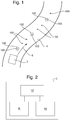
- Figure 1 is a schematic illustration (not to scale) of an example scenario in which an embodiment of a system and method for autonomously navigating a vehicle 2 is implemented.
- the vehicle 2 is an autonomous, land-based vehicle.
- the vehicle travels along a road 4.
- the vehicle travels in a direction indicated by an arrow in Figure 1 and the reference numeral 6.
- GPS Global Positioning System
- the satellite signals received at the O-points 102 are used by the vehicle 2 to determine the global position of the vehicle 2, as described in more details later below.
- the vehicle 2 taking measurements at the X-points 100, and the vehicle 2 receiving signals at the O-points 102 form part of the method for navigating a vehicle 2, which is described in more detail later below.
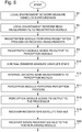
- Figure 2 is a schematic illustration of the vehicle 2.
- the vehicle 2 comprises a module for inter alia taking (at the X-points 100) and processing measurements of the vehicle's surroundings (i.e. the vehicle's 'local' environment).
- This module facilitates the motion of the vehicle 2 within its local environment.
- this module is hereinafter referred to as the "local motion module” and is indicated in Figure 2 by the reference numeral 8.
- the local motion module 8 is described in more detail later below with reference to Figure 3 .
- the vehicle 2 comprises a further module for inter alia receiving (at the O-points 102) and processing satellite signals measurements.
- This module facilitates the movement/positioning of the vehicle 2 within its global environment.
- this module is hereinafter referred to as the "global position module” and is indicated in Figure 2 by the reference numeral 10.
- the global position module 10 is described in more detail later below with reference to Figure 4 .
- the vehicle 2 comprises a processor 12.
- the processor 12 is connected to each of the local motion module 8 and the global position module 10.
- the processor 12 receives a signal (i.e. an output) from each of the local motion module 8 and the global position module 10.
- the processor 12 processes these signals as part of the vehicle navigation method, as described in more detail later below.
- Figure 3 is a schematic illustration (not to scale) of the local motion module 8.
- the local motion module 8 comprises a first plurality of sensors, hereinafter referred to as the "local environment sensors” and indicated in Figure 3 by the reference numeral 14, a second plurality of sensors, hereinafter referred to as the “internal sensors” and indicated in Figure 3 by the reference numeral 15, a so-called “registration module 16", and a so-called “perception module 18".
- the local environment sensors 14 are arranged to take measurements of the local environment of the vehicle 2.
- the local environment sensors 14 comprise a visible light detecting camera, and a Light Detecting and Ranging (LIDAR) system. Also, the local environment sensors 14 are adapted to detect obstacles or objects in a vicinity of the vehicle 2.
- LIDAR Light Detecting and Ranging
- the local environment sensors 14 are relatively low-error and relatively high-drift sensors. In other words the error between the actual value of a parameter measured by a local environment sensor 14, and the value of that parameter as measured by that local environment sensor 14 is relatively small. Also, the change in the output signal of a local environment sensor 14 over time, independent of the measured property, is relatively large.
- measurements of the local environment of the vehicle 2 are taken.
- the frame of reference with respect to which the measurements of the vehicle's local environment are taken is substantially fixed with respect to a current state of the vehicle (i.e. the state of the vehicle is assumed to be known accurately and acts as the fixed point for this reference frame).
- This frame of reference may be conveniently thought of as a "local" frame of reference (for the vehicle 2).
- the local frame uses a Cartesian co-ordinate system (time, position, orientation, velocities, turn rates and accelerations).
- the fixed point is the current vehicle state.
- the coordinate system origin corresponds to the vehicle's start-up state.
- the summation of changes method is used to estimate a change for the origin of the coordinate system with respect to the fixed point for the local frame (i.e. the vehicle's current state).
- the change in state of the vehicle with respect to the origin and vice versa is the mathematical inverse of each other. Therefore, within the local frame, as additional state changes are summed over time the accuracy of the estimate of the coordinate system origin tends to decrease, but the vehicle's state is known exactly.
- the estimate of the origin moves with respect to the global frame(s) and the start-up location.
- the local environment sensors 14 are connected to the registration module 16 such that, in operation, measurements taken by the local environment sensors 14 of the vehicle's surroundings (i.e. local environment) are transmitted from the local environment sensors 14 to the registration module 16.
- the registration module 16 performs a registration process (i.e. an image registration process) on the received measurements.
- a registration process i.e. an image registration process
- localisation information previously gathered and processed by the vehicle is used to perform the image registration process. This registration process is described in more detail later below with reference to Figure 5 .
- the registration module 16 is connected to the perception module 18 such that, in operation, an output of the registration module 16 is transmitted from the registration module 16 to the perception module 18.
- the internal sensors 15 are arranged to take measurements indicative of an internal state of the vehicle 2.
- the internal sensors 15 comprise an inertial measurement unit (IMU), and sensors arranged to measure the vehicle's wheel odometry.
- IMU inertial measurement unit
- the IMU measures the vehicle's velocity, orientation, and gravitational forces acting upon the vehicle 2.
- the internal sensors 15 are relatively low-error and relatively high-drift sensors.
- the internal sensors 15 are connected to the perception module 18 such that, in operation, measurements taken by the internal sensors 15 of an internal state of the vehicle 2 are transmitted from the internal sensors 15 to the perception module 18.
- the perception module 18 performs a perception process (i.e. a process by which the vehicle 2 may "perceive” or learn about its environment) on the received signals (from the internal sensors 15 and the registration module 16), as described in more detail later below with reference to Figure 5 .
- a perception process i.e. a process by which the vehicle 2 may "perceive” or learn about its environment
- the perception module 18 is connected to the processor 12 such that, in operation, an output of the perception module 18 is transmitted from the perception module 18 to the processor 12.
- Figure 4 is a schematic illustration (not to scale) of the global position module 10.
- the global position module 10 comprises a receiver 20, a so-called “map module 22", a so-called “mission module 23”, and a so-called “route planning module 24".
- the receiver 20 is arranged to receive the signals from the satellites (received at the O-points 102).
- the receiver 20 is a relatively high-error and relatively low-drift sensor.
- the error between the actual value of a vehicle position on Earth and the value of that position as received by the receiver 20 is relatively large.
- the change in the output signal of the receiver 20 over time, independent of the vehicle's position is relatively small.
- GPS signals received by the vehicle 2 from the satellites are indicative of vehicle's position etc. with respect to the Earth.
- the frame of reference with respect to which the measurements of the vehicle's global position are taken is substantially fixed with respect to the Earth.
- the Earth is, in effect, an entity that is different to the vehicle 2.
- the vehicle 2 is moveable with respect to that entity (and so is moveable with respect to the frame of reference that is fixed with respect to the entity).
- This frame of reference may be conveniently thought of as a "global" frame of reference (for the vehicle 2).
- the global frame is a combination of a Cartesian co-ordinate system (time, position, orientation, velocities, turn rates and accelerations) and a fixed point at the coordinate system origin which corresponds to a fixed point on the Earth.
- the WGS84 Universal Transverse Mercator standard is used.
- the global frame is used as a common system for information exchange between entities, e.g. a user sends an autonomous vehicle to a point on the Earth. When performing localisation, the state of the vehicle is estimated with respect to the origin (fixed point).
- the receiver 20 is connected to the route planning module 24 such that, in operation, the received satellite signals are transmitted from the receiver 20 to the route planning module 24.
- the map module 22 comprises a map of the region in which the vehicle 2 is to be operated in. This may be considered to be a map of the vehicle's global environment. In this embodiment, the map comprises the location of points along the road 4.
- the map module 22 is connected to the route planning module 24 such that, in operation, the map loaded into the map module 22 (i.e. the map of the vehicle's global environment) is transmitted from the map module 22 to the route planning module 24.
- the mission module 23 comprises a mission, or task, to be completed by the vehicle 2.
- the mission for the vehicle is loaded onto the mission module (by a user of the vehicle 2).
- the mission, or task, for the vehicle 2 is for the vehicle 2 to travel along the road 4 and avoid any obstacles present (i.e. avoid crashing).
- the mission module 23 is connected to the route planning module 24 such that, in operation, the mission details loaded into the mission module 23 (i.e. the vehicle's task) is transmitted from the mission module 23 to the route planning module 24.
- the route planning module 24 performs a route planning process (i.e. it determines a route for the vehicle 2) on the received map, such that the received mission is completed, using the received satellite signals. This process is described in more detail later below with reference to Figure 5 .
- the route planning module 24 is connected to the processor 12 such that, in operation, an output of the route planning module 24 (i.e. the planned route for the vehicle 2) is transmitted from the route planning module 24 to the processor 12.
- the processor 12 performs a so-called "transformation process" using the received output of the route planning module 24 and the received output from the perception module 18.
- the transformation process is performed to determine a transformation of the route determined by the route planning module 24 from the vehicle's global frame (i.e. the map) into the vehicle's local frame (i.e. the vehicle's local environment). This process is described in more detail later below with reference to Figure 5 .
- Apparatus including the processor 12 and the various modules, for implementing the above arrangement, and performing the method steps to be described later below, may be provided by configuring or adapting any suitable apparatus, for example one or more computers or other processing apparatus or processors, and/or providing additional modules.
- the apparatus may comprise a computer, a network of computers, or one or more processors, for implementing instructions and using data, including instructions and data in the form of a computer program or plurality of computer programs stored in or on a machine readable storage medium such as computer memory, a computer disk, ROM, PROM etc., or any combination of these or other storage media.
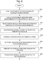
- Figure 5 is a process flow chart showing certain steps of an embodiment of a vehicle navigation method, as implemented in the scenario of Figure 1 .
- the local environment sensors 14 take measurements of the vehicle's surroundings.
- these measurements are taken at regular, and relatively frequent, intervals as the vehicle 2 travels along the road 4 (i.e. at each of the X-points 100).
- the measurements taken by the local environment sensors 14 of the vehicle's surroundings include visible light images taken by the on-board visible light detecting camera, and laser range-based images taken by the on-board LIDAR system.
- step s4 as the measurements (i.e. the images) are taken by the local environment sensors 14, they are transmitted to the registration module 16.
- all measurements taken at a given X-point 100 are transmitted to the registration module 16, e.g. whilst the vehicle 2 is at that X-point 100 (i.e. before measurements are taken for the next X-point 100).
- the registration module 16 performs a registration process on the received measurements of the vehicle's surroundings.
- a conventional registration process is performed by the registration module.
- the registration process comprises performing a series of Special Euclidean group, SE(3), transformations (rotation and translations) on the images. Further details on performing SE(3) transformations can be found in Chapter 3.2.3 3D Transforms, Planning Algorithms, ISBN 9780521862059 .
- the registration module 16 produces a registered set of images using the images received from the local environment sensors 14 that correspond to a particular X-point 100.
- the output of the registration process (performed at step s6) is transmitted from the registration module 16 to the perception module 18.
- a registered set of images (that has been determined from the measurements taken at a particular X-point 100) is sent from the registration module 16 to the perception module 18.
- the internal sensors 15 take measurements of the vehicle's internal state.
- these measurements are taken at regular, and relatively frequent, intervals as the vehicle 2 travels along the road 4 (i.e. at each of the X-points 100).
- the measurements taken by the internal sensors 15 comprise a linear acceleration and an angular velocity for the vehicle (measured by the IMU), and measurements of the vehicle's wheel odometry.
- the measurements taken by the internal sensors 15 are transmitted to the perception module 18.
- the perception module 18 performs a perception process using the output of the registration process corresponding to a particular X-point 100 (sent to the perception module 18 at step s8) and the measurements of the vehicle's internal state at that X-point 100 (sent to the perception module 18 at step s12).
- the perception process performed so that, in effect, the vehicle 2 is 'localised' in its local environment.
- the position etc. of the vehicle 2 with respect to its surroundings (as measured by the local environment sensors) at a particular X-point 100 is determined.
- the perception process performed by the perception module 18 in this embodiment is a conventional autonomous vehicle perception process. Further details on an example perception process can be found in Chapter 9 Occupancy Grid Mapping, Probabilistic Robotics, ISBN 9780262201629 .
- the vehicle's perception i.e. the output of the perception process performed at step s14
- the vehicle's perception of its surrounding is updated as measurements for successive X-points 100 are taken and processed.
- an output of the perception process performed at step s14 is a 3D-map, or model, of the vehicle's surroundings, i.e. the local environment of the vehicle 2.
- the perception process detects objects or obstacles in the local environment of the vehicle 2.
- a feature extraction process may be performed on the images taken by the local environment sensors 14 to detect objects/obstacles in those images.
- the output of the perception process performed by the perception module 18 at step s14 (i.e. the map or model of the vehicle's surroundings) is sent from the perception module 18 to the processor 12.
- the receiver 20 receives signals from the global positioning satellites.
- these GPS signals are received at regular intervals as the vehicle 2 travels along the road 4 (i.e. at each of the O-points 102).
- these GPS signals are received at a lower frequency than the frequency with which the vehicle takes measurements of its surroundings.
- the amount of time between two successive GPS signals being received by the receiver 20 is larger than the amount of between two successive measurements of the local environment of the vehicle 2 taken by the local environment sensors 14 (or indeed the amount of time between two successive measurements of the internal state of the vehicle 2 taken by the internal sensors 15).
- the satellite signals received at the receiver 20 are sent from the receiver 20 to the route planning module 24.
- the map loaded into the map module 22 is sent from the map module 22 to the route planning module 24.
- the details of the vehicle's mission (i.e. the task to be performed by the vehicle 2) is sent from the mission module 23 to the route planning module 24
- the route planning module 24 determines a route for vehicle 2 using the received satellite signals, map, and mission details.
- the satellite signals are used by the route planning module 24 to determine a current position for the vehicle 2 on the map.
- the route generated by the route planning module is such that the mission is completed by the vehicle 2, i.e. in this embodiment the determined route for the vehicle 2 is along the road 4.
- the route i.e. the output from the route planning module 24
- the route planning module 24 is updated as further GPS satellite signals are received at the receiver 20 and sent to the route planning module 24 for processing.
- a route for the vehicle to complete its mission is updated as signals received at successive O-points 102 are processed.
- the route determined by the route planning module 24 is sent from the route planning module 24 to the processor 12.
- the processor 12 performs a transformation process using the route generated at step s26.
- the transformation process is performed to determine a transformation of the determined route from the vehicle's global frame (i.e. the map) into the vehicle's local frame (i.e. the vehicle's local environment).
- a conventional process for determining a transformation and transforming the route comprises performing a series of Special Euclidean group, SE(3), transformations (rotation and translations). Further details on performing SE(3) transformations can be found in Chapter 3.2.3 3D Transforms, Planning Algorithms, ISBN 9780521862059 .
- the processor 12 receives a 3D-map, or model, of the vehicle's surroundings, and has determined a route in the frame of the vehicle's local environment.
- the processor 12 performs a path planning process.
- This path planning process is performed using the received output of the perception process and the output of the transformation process to determine a path for the vehicle 2. This path is such that the vehicle 2 avoids any objects/obstacles that were detected in the local environment of the vehicle 2, and such that the vehicle would complete its mission if it followed the path.
- low-error high-drift sensors such as the IMU of the local environment sensors 14
- high-error low-drift sensor such as the GPS
- the processor 12 controls the vehicle 2 in such a way that the vehicle 2 follows the path determined at step s36.
- An advantage provided by the above described system and method for navigating a vehicle is that the vehicle tends to avoid objects/obstacles present in its local surroundings, whilst being able to position itself in a global frame (i.e. in the world).
- the above described system and method tends to advantageously use of two separate co-ordinate frames: one for supporting locally gathered information, and one for remotely gathered (global) information.
- the system for supporting locally gathered information tends to be usable for aiding a driver, and/or performing local obstacle avoidance, terrain sensing and/or vehicle control without a need for GPS to start-up, and over unlimited GPS dropouts.
- This system tends to provide an estimate of the change of vehicle pose, but does not use an absolute measurement of position and orientation of the vehicle in a global frame (i.e. in this embodiment, it doesn't know where on the Earth the vehicle is).
- the system for supporting remotely gathered (global) information tends to be useable for route planning, mission planning, and multi-platform coordination. This system tends to provide an estimate of the absolute pose of the vehicle. It tends to be possible to only use this system (or only have this system operate relatively accurately) when the vehicle is to perform global tasks.
- a further advantage provided by the above described multi-frame localisation is that the performance of collision detection and avoidance tends to be decoupled from that of global localisation. This tends to reduce GPS dependence of the system elements required for safe autonomous navigation. Also, this tends to facilitate the use of more robust and lower accuracy global sensors (instead of or in addition to GPS) such as Signals of Opportunity for route and mission planning.
- a further advantage provided by the above described system is that the provision of reliable, low-cost autonomous systems tends to be facilitated.
- the above provided system and method tends to be robust to sensor failure/error from the GPS sensor.
- driver aid, local obstacle avoidance, terrain sensing and/or vehicle control tend to still be provided without global sensor operation.
- Unbounded or unlimited errors in the global position of the vehicle tend not to impact the performance of the local localisation system.
- This tends to be in contrast to conventional autonomous vehicles that tend to use an Inertial Navigation System (INS) for localisation, and whose performance is limited when operating in, for example, GPS intermittent environments.
- INS Inertial Navigation System
- the above described system and method tends to provide significant navigation advantages, even in when a GPS signal is not available or intermittent.
- a further advantage of the above described system and method is that a combination of multiple global sensors (e.g. GPS, RFID in the global environment, etc.) can be used for localisation and path planning. This tends to provide that more accurate localisation/planning solutions can be obtained. Furthermore, using a combination of different global sensors tends to provide a level of redundancy into the system. Thus, is one global sensor system (e.g. GPS) fails, a relatively accurate localisation/planning solution can still be determined using the remaining global sensors.
- GPS global sensor system
- a further advantage provided by the above described system is that the use of lower update rate global sensors, e.g. Wireless Hotspot / RFID localisation, (as opposed to or in addition to higher update rate global sensors, e.g. GPS) can be used to determine a relatively accurate localisation/planning solution.
- lower update rate global sensors e.g. Wireless Hotspot / RFID localisation
- higher update rate global sensors e.g. GPS
- GPS denial i.e. when a GPS signal is not available to the vehicle 2.
- Such a condition of GPS denial may occur if there is an error with the receiver 20, the GPS satellites, or if the signal from the satellites to the receiver 20 is blocked (e.g. if the vehicle 2 is operating indoors or in a tunnel etc.).
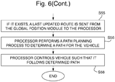
- Figure 6 is a process flow chart showing certain steps of the vehicle navigation method performed under a condition of "GPS denial".
- the local environment sensors 14 take measurements of the vehicle's surroundings.
- this step is performed in the same way as step s2 as described in more detail above with reference to Figure 5 .
- step s42 as the measurements (i.e. the images) are taken by the local environment sensors 14, they are transmitted to the registration module 16.
- this step is performed in the same way as step s4 as described in more detail above with reference to Figure 5 .
- the registration module 16 performs a registration process on the received measurements of the vehicle's surroundings to produce a registered set of images.
- this step is performed in the same way as step s6 as described in more detail above with reference to Figure 5 .
- the output of the registration process (performed at step s44) is transmitted from the registration module 16 to the perception module 18.
- this step is performed in the same way as step s8 as described in more detail above with reference to Figure 5 .
- the internal sensors 15 take measurements of the vehicle's internal state.
- this step is performed in the same way as step s10 as described in more detail above with reference to Figure 5 .
- the measurements taken by the internal sensors 15 are transmitted to the perception module 18.
- this step is performed in the same way as step s12 as described in more detail above with reference to Figure 5 .
- the perception module 18 performs a perception process using the output of the registration process corresponding to a particular X-point 100 (sent to the perception module 18 at step s46) and the measurements of the vehicle's internal state at that X-point 100 (sent to the perception module 18 at step s50).
- this step is performed in the same way as step s14 as described in more detail above with reference to Figure 5 .
- the output of the perception process performed by the perception module 18 at step s52 (i.e. the map or model of the vehicle's surroundings) is sent from the perception module 18 to the processor 12.
- this step is performed in the same way as step s16 as described in more detail above with reference to Figure 5 .
- a last updated route is transmitted from the global position module 10 to the processor 12. If no such route exists, no signal is transmitted from the global position module 10 to the processor 12 at this step.
- a last updated route is understood to be the route that was determined by the route planning module 24 using the GPS signals most recently received at the receiver 20.
- a last updated route may not exist, for example, if no GPS signals have yet been received by the vehicle 2.
- the processor 12 performs a path planning process is using the received output of the perception process (sent to the processor 12 at step s54 above) and, if transmitted at step s55, the last updated route (which is transformed by the processor 12 as described above with reference to step s30 of Figure 5 ).
- this step is performed in the same way as step s36 as described in more detail above with reference to Figure 5 .
- the path for the vehicle 2 is determined at step s56 using the measurements taken by the local environment sensors 14 and the internal sensors 15 alone.
- the vehicle 2 still operates relatively safely under the condition of GPS denial as a path that avoids obstacles/objects is determined for the vehicle 2.
- the vehicle's position along the route is estimated by the processor 12 using the measurements taken by the local environment sensors 14 and the internal sensors 15 (e.g. the position of the vehicle 2 may be estimated using measurements of the vehicle's wheel odometry, linear acceleration, and angular velocity etc.).
- the local environment sensors 14 and the internal sensors 15 are high-drift sensors (as described in more detail above with reference to Figure 3 )
- the uncertainty/error associated with the estimate of the vehicle's position along the route will increase in time. This error is unbounded. This uncertainty/error will be reduced once a GPS signal is received. Nevertheless, the vehicle 2 still operates relatively safely under the condition of GPS denial as a path avoids obstacles/objects (and that approximately follows the last determined route) is determined for the vehicle 2.
- the processor 12 controls the vehicle 2 in such a way that the vehicle 2 follows the path determined at step s56.
- the vehicle is a land-based, autonomous vehicle.
- the vehicle is a different type of vehicle.
- the vehicle is an aircraft or sea-based vehicle and/or the vehicle is a semi-autonomous vehicle.
- the vehicle navigation system and method is implemented in the scenario of Figure 1 .
- the vehicle is tasked to drive along the road.
- the method/system is implemented in a different scenario, e.g. a scenario in which the vehicle is to perform a different task.
- the vehicle may be tasked to follow a sequence of way-points, and/or deliver a payload to a particular location.
- the system and method was implemented using a single vehicle.
- the system/method is implemented using a different number of vehicles, e.g. a team of vehicles.
- the vehicles may communicate with other, for example, such that a path for each vehicle is determined depending on the paths for the other vehicles.
- measurements of the vehicle's surroundings i.e. local environment
- measurements of the internal state of the vehicle are taken at regular intervals (i.e. at each of the X-points).
- measurements of the vehicle's surroundings and/or the measurements of the internal state of the vehicle are taken at irregular intervals.
- the measurements of the vehicle's surroundings are taken at different times to the measurements of the internal state of the vehicle are taken.
- the measurements of the vehicle's surroundings and/or the measurements of the internal state of the vehicle may be taken at discrete time-steps, or continuously.
- GPS signals are received by the vehicle at regular intervals. However, in other embodiments GPS signals are received by the vehicle at irregular intervals. Also, GPS signals may be received by the vehicle at discrete time-steps, or continuously.
- measurements of the vehicle's surroundings and the measurements of the internal state of the vehicle are taken more frequently than the GPS signals are received.
- measurements of the vehicle's surroundings and/or the measurements of the internal state of the vehicle are taken less frequently than, or with substantially the same frequency as, the GPS signals are received.
- the local environment sensors comprise a visible light detecting camera, and a LIDAR system.
- the local environment sensors include one or more different appropriate sensors instead of or in addition to the camera and/or the LIDAR system.
- the local environments sensors comprise a Radar system for detecting objects close to the vehicle, or an ultraviolet (UV) or infrared (IR) camera.
- UV ultraviolet
- IR infrared
- the internal sensors comprise an IMU and a sensor arranged to measure the wheel odometry of the vehicle.
- the internal sensors include one or more different appropriate sensors instead of or in addition to the IMU and/or wheel odometry sensor, e.g. a visible light detecting camera.
- a global position for the vehicle is estimated/determined using a GPS.
- the receiver of the vehicle receives GPS signals from GPS satellites. These signals are then processed to determined a position for the vehicle.
- a different system for determining/estimating a global (i.e. not local) position for the vehicle is used. For example, a process using Signals of Opportunity (e.g. from a mobile telephone mast) may be performed instead of or in addition implementing the GPS.
- the vehicle comprises more than one different position system.
- Each of these systems provides a global position for the vehicle determined using a different method used by each of the other systems.
- the positions provided by these systems may be amalgamated to provide a 'fused' global position for path planning.
- the positions provided by these systems may be 'ordered' (i.e. put in order of preference) such that, of the determined positions for a given time-step, a sub-set of the determined positions may be used for path planning.
- the positions used for path planning may be selected depending on the conditions in which the vehicle is operating (e.g. the location, type of terrain etc), and how well the systems determining the positions operate in those conditions.
Landscapes
- Engineering & Computer Science (AREA)
- Radar, Positioning & Navigation (AREA)
- Remote Sensing (AREA)
- Physics & Mathematics (AREA)
- General Physics & Mathematics (AREA)
- Automation & Control Theory (AREA)
- Aviation & Aerospace Engineering (AREA)
- Electromagnetism (AREA)
- Optics & Photonics (AREA)
- Navigation (AREA)
- Traffic Control Systems (AREA)
- Computer Networks & Wireless Communication (AREA)
- Control Of Driving Devices And Active Controlling Of Vehicle (AREA)
- Chemical & Material Sciences (AREA)
- Combustion & Propulsion (AREA)
- Transportation (AREA)
- Mechanical Engineering (AREA)
Claims (12)
- Procédé pour établir un itinéraire pour un véhicule autonome (2), le procédé consistant à déterminer des informations de localisation du véhicule (2) par rapport à une trame de référence en réalisant un processus de perception pour localiser le véhicule (2) par rapport à la trame de référence, à déterminer un itinéraire pour le véhicule par rapport à la trame de référence et à commander le véhicule (2) de telle sorte qu'il suive l'itinéraire déterminé,
caractérisé en ce que le procédé consiste :à déterminer des informations de localisation du véhicule (2) par rapport à une première trame de référence en utilisant un ou plusieurs capteurs (14) pour mesurer des valeurs d'un paramètre dans l'environnement local du véhicule, la première trame de référence étant une trame de référence qui est fixe par rapport à un état actuel du véhicule (2) ;à déterminer des informations de localisation du véhicule (2) par rapport à une seconde trame de référence en réalisant un processus de perception pour localiser le véhicule (2) par rapport à la seconde trame de référence en recevant des signaux en provenance d'un capteur d'erreur élevée à faible dérive (20), la seconde trame de référence étant une trame de référence qui est fixe par rapport à une entité, l'entité étant différente du véhicule (2) et le véhicule (2) étant mobile par rapport à l'entité ;à établir un itinéraire pour le véhicule (2) par rapport à la seconde trame de référence à l'aide des informations de localisation du véhicule (2) par rapport à la seconde trame de référence ;à réaliser une transformation de l'itinéraire, en passant de la seconde trame de référence à la première trame de référence, ce qui permet de fournir un itinéraire transformé ;à déterminer un itinéraire pour le véhicule (2) par rapport à la première trame de référence à l'aide des informations de localisation du véhicule (2) par rapport à la première trame de référence et à l'itinéraire transformé ; età commander le véhicule (2) de telle sorte qu'il suive l'itinéraire déterminé ;le procédé étant réalisé dans un environnement dans lequel les signaux reçus du capteur d'erreur élevée à faible dérive (20) sont reçus à une fréquence inférieure à la fréquence avec laquelle le véhicule (2) mesure des valeurs d'un paramètre dans l'environnement local du véhicule. - Procédé selon la revendication 1, dans lequel le ou les capteurs (14) comprennent une caméra de détection de lumière visible et/ou un capteur de détection et de télémétrie par la lumière.
- Procédé selon l'une ou l'autre des revendications précédentes, dans lequel l'étape de détermination d'informations de localisation du véhicule (2) par rapport à une première trame de référence consiste en outre à réaliser un processus de détection d'objet à l'aide des valeurs de paramètre mesurées et les informations de localisation du véhicule (2) par rapport à une première trame de référence comportent des informations se rapportant à des objets détectés dans l'environnement local du véhicule.
- Procédé selon la revendication 3, dans lequel l'itinéraire déterminé est tel que, lorsque le véhicule doit suivre l'itinéraire déterminé, des objets détectés seraient évités.
- Procédé selon l'une quelconque des revendications 1 à 4, dans lequel l'entité est la Terre.
- Procédé selon la revendication 5, dans lequel l'étape de détermination d'informations de localisation du véhicule (2) par rapport à une seconde trame de référence consiste à recevoir un signal en provenance d'un satellite de système mondial de positionnement.
- Procédé selon l'une quelconque des revendications 1 à 6, le procédé consistant à spécifier une tâche pour le véhicule (2), dans lequel l'itinéraire déterminé est tel que, lorsque le véhicule (2) doit suivre l'itinéraire déterminé, la tâche serait achevée.
- Procédé selon l'une quelconque des revendications 1 à 7, dans lequel le véhicule (2) est un véhicule terrestre.
- Appareil pour établir un itinéraire pour un véhicule autonome (2), l'appareil comprenant un ou plusieurs processeurs conçus pour déterminer des informations de localisation du véhicule (2) par rapport à une trame de référence en réalisant un processus de perception pour localiser le véhicule (2) par rapport à la trame de référence, pour déterminer un itinéraire pour le véhicule par rapport à la trame de référence et pour commander le véhicule (2) de telle sorte qu'il suive l'itinéraire déterminé,
caractérisé en ce que le ou les processeurs sont conçus :pour déterminer des informations de localisation du véhicule (2) par rapport à une première trame de référence en utilisant un ou plusieurs capteurs (14) pour mesurer des valeurs d'un paramètre dans l'environnement local du véhicule, la première trame de référence étant une trame de référence qui est fixe par rapport à un état actuel du véhicule (2) ;pour déterminer des informations de localisation du véhicule (2) par rapport à une seconde trame de référence en réalisant un processus de perception pour localiser le véhicule (2) par rapport à la seconde trame de référence en recevant des signaux en provenance d'un capteur d'erreur élevée à faible dérive (20), la seconde trame de référence étant une trame de référence qui est fixe par rapport à une entité, l'entité étant différente du véhicule (2) et le véhicule (2) étant mobile par rapport à l'entité ;pour établir un itinéraire pour le véhicule (2) par rapport à la seconde trame de référence à l'aide des informations de localisation du véhicule par rapport à la seconde trame de référence ;pour réaliser une transformation de l'itinéraire, en passant de la seconde trame de référence à la première trame de référence, ce qui permet de fournir un itinéraire transformé ;pour déterminer un itinéraire pour le véhicule (2) par rapport à la première trame de référence à l'aide des informations de localisation du véhicule (2) par rapport à la première trame de référence et à l'itinéraire transformé ; etpour commander le véhicule (2) de telle sorte qu'il suive l'itinéraire déterminé ;les signaux reçus du capteur d'erreur élevée à faible dérive (20) sont reçus à une fréquence inférieure à la fréquence avec laquelle le véhicule (2) mesure des valeurs d'un paramètre dans l'environnement local du véhicule. - Véhicule comprenant l'appareil selon la revendication 9.
- Programme ou pluralité de programmes conçus de telle sorte que, lorsqu'ils sont exécutés par un système informatique ou par un ou plusieurs processeurs, il contraint, ou ils contraignent, le système informatique ou le ou les processeurs à fonctionner selon le procédé selon l'une quelconque des revendications 1 à 8.
- Support de stockage lisible par une machine stockant un programme ou au moins un programme de la pluralité de programmes selon la revendication 11.
Priority Applications (1)
| Application Number | Priority Date | Filing Date | Title |
|---|---|---|---|
| EP12724700.5A EP2715470B1 (fr) | 2011-05-24 | 2012-05-22 | Navigation embarquée |
Applications Claiming Priority (4)
| Application Number | Priority Date | Filing Date | Title |
|---|---|---|---|
| EP11250557A EP2527943A1 (fr) | 2011-05-24 | 2011-05-24 | Navigation de véhicule |
| GB201108965A GB201108965D0 (en) | 2011-05-24 | 2011-05-24 | Vehicle navigation |
| PCT/GB2012/051156 WO2012160373A2 (fr) | 2011-05-24 | 2012-05-22 | Navigation embarquée |
| EP12724700.5A EP2715470B1 (fr) | 2011-05-24 | 2012-05-22 | Navigation embarquée |
Publications (2)
| Publication Number | Publication Date |
|---|---|
| EP2715470A2 EP2715470A2 (fr) | 2014-04-09 |
| EP2715470B1 true EP2715470B1 (fr) | 2018-07-11 |
Family
ID=46197618
Family Applications (1)
| Application Number | Title | Priority Date | Filing Date |
|---|---|---|---|
| EP12724700.5A Active EP2715470B1 (fr) | 2011-05-24 | 2012-05-22 | Navigation embarquée |
Country Status (4)
| Country | Link |
|---|---|
| US (1) | US9122278B2 (fr) |
| EP (1) | EP2715470B1 (fr) |
| AU (1) | AU2012260626C1 (fr) |
| WO (1) | WO2012160373A2 (fr) |
Families Citing this family (12)
| Publication number | Priority date | Publication date | Assignee | Title |
|---|---|---|---|---|
| EP2715470B1 (fr) * | 2011-05-24 | 2018-07-11 | BAE Systems PLC | Navigation embarquée |
| US9404761B2 (en) | 2014-05-30 | 2016-08-02 | Nissan North America, Inc. | Autonomous vehicle lane routing and navigation |
| EP3171133B1 (fr) * | 2015-11-19 | 2020-03-11 | Sikorsky Aircraft Corporation | Planification de mouvement cinématique avec contraintes de planification régionale |
| US10460600B2 (en) | 2016-01-11 | 2019-10-29 | NetraDyne, Inc. | Driver behavior monitoring |
| WO2017123665A1 (fr) | 2016-01-11 | 2017-07-20 | Netradyne Inc. | Surveillance du comportement d'un conducteur |
| US10801852B2 (en) * | 2016-01-29 | 2020-10-13 | Komatsu Ltd. | Work machine management system and work machine |
| WO2017165627A1 (fr) | 2016-03-23 | 2017-09-28 | Netradyne Inc. | Prédiction de trajet avancée |
| US10179583B2 (en) | 2016-03-29 | 2019-01-15 | Ford Global Technologies, Llc | Vehicle subsystem coordination and control |
| CN108508899A (zh) * | 2018-05-07 | 2018-09-07 | 湖北汽车工业学院 | 一种无人驾驶车辆轨迹跟踪控制行驶系统 |
| JP7141883B2 (ja) * | 2018-07-31 | 2022-09-26 | 株式会社小松製作所 | 作業機械の制御システム、作業機械、及び作業機械の制御方法 |
| US11372100B2 (en) * | 2018-10-23 | 2022-06-28 | Baidu Usa Llc | Radar object classification and communication using smart targets |
| CN113561994B (zh) * | 2021-08-13 | 2022-04-05 | 北京三快在线科技有限公司 | 轨迹规划方法、装置、存储介质及电子设备 |
Citations (3)
| Publication number | Priority date | Publication date | Assignee | Title |
|---|---|---|---|---|
| US20020099481A1 (en) * | 2001-01-22 | 2002-07-25 | Masaki Mori | Travel controlling apparatus of unmanned vehicle |
| EP1898181A1 (fr) * | 2006-09-05 | 2008-03-12 | Honeywell International, Inc. | Procédé et système pour la navigation autonome d'un véhicule |
| US20100106356A1 (en) * | 2008-10-24 | 2010-04-29 | The Gray Insurance Company | Control and systems for autonomously driven vehicles |
Family Cites Families (6)
| Publication number | Priority date | Publication date | Assignee | Title |
|---|---|---|---|---|
| US7499775B2 (en) * | 2004-10-22 | 2009-03-03 | Irobot Corporation | System and method for terrain feature tracking |
| US7228230B2 (en) * | 2004-11-12 | 2007-06-05 | Mitsubishi Denki Kabushiki Kaisha | System for autonomous vehicle navigation with carrier phase DGPS and laser-scanner augmentation |
| US8050863B2 (en) | 2006-03-16 | 2011-11-01 | Gray & Company, Inc. | Navigation and control system for autonomous vehicles |
| US20100066587A1 (en) | 2006-07-14 | 2010-03-18 | Brian Masao Yamauchi | Method and System for Controlling a Remote Vehicle |
| US8364334B2 (en) * | 2008-10-30 | 2013-01-29 | Honeywell International Inc. | System and method for navigating an autonomous vehicle using laser detection and ranging |
| EP2715470B1 (fr) * | 2011-05-24 | 2018-07-11 | BAE Systems PLC | Navigation embarquée |
-
2012
- 2012-05-22 EP EP12724700.5A patent/EP2715470B1/fr active Active
- 2012-05-22 WO PCT/GB2012/051156 patent/WO2012160373A2/fr not_active Ceased
- 2012-05-22 AU AU2012260626A patent/AU2012260626C1/en active Active
- 2012-05-22 US US14/122,147 patent/US9122278B2/en active Active
Patent Citations (3)
| Publication number | Priority date | Publication date | Assignee | Title |
|---|---|---|---|---|
| US20020099481A1 (en) * | 2001-01-22 | 2002-07-25 | Masaki Mori | Travel controlling apparatus of unmanned vehicle |
| EP1898181A1 (fr) * | 2006-09-05 | 2008-03-12 | Honeywell International, Inc. | Procédé et système pour la navigation autonome d'un véhicule |
| US20100106356A1 (en) * | 2008-10-24 | 2010-04-29 | The Gray Insurance Company | Control and systems for autonomously driven vehicles |
Also Published As
| Publication number | Publication date |
|---|---|
| WO2012160373A2 (fr) | 2012-11-29 |
| AU2012260626C1 (en) | 2015-12-10 |
| EP2715470A2 (fr) | 2014-04-09 |
| US9122278B2 (en) | 2015-09-01 |
| US20140136046A1 (en) | 2014-05-15 |
| WO2012160373A3 (fr) | 2013-05-10 |
| AU2012260626B2 (en) | 2015-08-13 |
Similar Documents
| Publication | Publication Date | Title |
|---|---|---|
| EP2715470B1 (fr) | Navigation embarquée | |
| AU2012260626A1 (en) | Vehicle navigation | |
| EP3715785B1 (fr) | Système de navigation inertielle assisté par slam | |
| EP3237982B1 (fr) | Véhicule assisté et guidé de manière autonome | |
| CN108955688B (zh) | 双轮差速移动机器人定位方法及系统 | |
| EP2527943A1 (fr) | Navigation de véhicule | |
| EP4276564B1 (fr) | Calcul de position basé sur des capteurs d'image et de distance et procédé associé | |
| KR20220033477A (ko) | 자동 발렛 파킹 시스템의 위치 추정 장치 및 방법 | |
| RU2735567C1 (ru) | Способ хранения предысторий движения, способ для выработки модели пути движения, способ для оценки локальной позиции и устройство хранения предысторий движения | |
| EP3905213B1 (fr) | Dispositif de positionnement et corps mobile | |
| WO2007143757A2 (fr) | Architecture logicielle permettant de parcourir à grande vitesse des itinéraires prescrits | |
| EP1548534B1 (fr) | Procédé et appareil pour utiliser la quantité de mouvement en rotation d'un dispositif mobile et support d'enregistrement pouvant être lu par un ordinateur pour stocker un programme informatique | |
| Teixeira et al. | Autonomous aerial inspection using visual-inertial robust localization and mapping | |
| US12535322B2 (en) | System and methods of vehicle pose estimation | |
| Alam et al. | Fiducial markers and particle filter based localization and navigation framework for an autonomous mobile robot | |
| Li et al. | Indoor localization for an autonomous model car: A marker-based multi-sensor fusion framework | |
| Krejsa et al. | Fusion of local and global sensory information in mobile robot outdoor localization task | |
| US12130635B2 (en) | Information processing system and information processing apparatus | |
| EP4269044B1 (fr) | Procédé et appareil de correction d'emplacement de pente, robot et support de stockage lisible | |
| Nastro | Position and orientation data requirements for precise autonomous vehicle navigation | |
| Coble et al. | Motion model and filtering techniques for scaled vehicle localization with Fiducial marker detection | |
| Rodríguez Castaño et al. | Fuzzy path tracking and position estimation of autonomous vehicles using differential GPS | |
| CN120576781B (zh) | 一种园区无人车的定位与路径规划方法和系统 | |
| Wu et al. | A Vision-Assisted Approach of Autonomous Navigation for Indoor AGV | |
| US11892852B2 (en) | Information processing apparatus and information processing method |
Legal Events
| Date | Code | Title | Description |
|---|---|---|---|
| PUAI | Public reference made under article 153(3) epc to a published international application that has entered the european phase |
Free format text: ORIGINAL CODE: 0009012 |
|
| 17P | Request for examination filed |
Effective date: 20131212 |
|
| AK | Designated contracting states |
Kind code of ref document: A2 Designated state(s): AL AT BE BG CH CY CZ DE DK EE ES FI FR GB GR HR HU IE IS IT LI LT LU LV MC MK MT NL NO PL PT RO RS SE SI SK SM TR |
|
| RIN1 | Information on inventor provided before grant (corrected) |
Inventor name: SMITH, CHRISTOPHER, ANDREW Inventor name: HESTER, GEOFFREY JAMES |
|
| DAX | Request for extension of the european patent (deleted) | ||
| STAA | Information on the status of an ep patent application or granted ep patent |
Free format text: STATUS: EXAMINATION IS IN PROGRESS |
|
| 17Q | First examination report despatched |
Effective date: 20170320 |
|
| GRAP | Despatch of communication of intention to grant a patent |
Free format text: ORIGINAL CODE: EPIDOSNIGR1 |
|
| STAA | Information on the status of an ep patent application or granted ep patent |
Free format text: STATUS: GRANT OF PATENT IS INTENDED |
|
| INTG | Intention to grant announced |
Effective date: 20180130 |
|
| GRAS | Grant fee paid |
Free format text: ORIGINAL CODE: EPIDOSNIGR3 |
|
| GRAA | (expected) grant |
Free format text: ORIGINAL CODE: 0009210 |
|
| STAA | Information on the status of an ep patent application or granted ep patent |
Free format text: STATUS: THE PATENT HAS BEEN GRANTED |
|
| AK | Designated contracting states |
Kind code of ref document: B1 Designated state(s): AL AT BE BG CH CY CZ DE DK EE ES FI FR GB GR HR HU IE IS IT LI LT LU LV MC MK MT NL NO PL PT RO RS SE SI SK SM TR |
|
| REG | Reference to a national code |
Ref country code: GB Ref legal event code: FG4D |
|
| REG | Reference to a national code |
Ref country code: CH Ref legal event code: EP |
|
| REG | Reference to a national code |
Ref country code: AT Ref legal event code: REF Ref document number: 1017545 Country of ref document: AT Kind code of ref document: T Effective date: 20180715 |
|
| REG | Reference to a national code |
Ref country code: DE Ref legal event code: R096 Ref document number: 602012048352 Country of ref document: DE |
|
| REG | Reference to a national code |
Ref country code: IE Ref legal event code: FG4D |
|
| REG | Reference to a national code |
Ref country code: NL Ref legal event code: MP Effective date: 20180711 |
|
| REG | Reference to a national code |
Ref country code: LT Ref legal event code: MG4D |
|
| REG | Reference to a national code |
Ref country code: AT Ref legal event code: MK05 Ref document number: 1017545 Country of ref document: AT Kind code of ref document: T Effective date: 20180711 |
|
| PG25 | Lapsed in a contracting state [announced via postgrant information from national office to epo] |
Ref country code: NL Free format text: LAPSE BECAUSE OF FAILURE TO SUBMIT A TRANSLATION OF THE DESCRIPTION OR TO PAY THE FEE WITHIN THE PRESCRIBED TIME-LIMIT Effective date: 20180711 |
|
| PG25 | Lapsed in a contracting state [announced via postgrant information from national office to epo] |
Ref country code: NO Free format text: LAPSE BECAUSE OF FAILURE TO SUBMIT A TRANSLATION OF THE DESCRIPTION OR TO PAY THE FEE WITHIN THE PRESCRIBED TIME-LIMIT Effective date: 20181011 Ref country code: GR Free format text: LAPSE BECAUSE OF FAILURE TO SUBMIT A TRANSLATION OF THE DESCRIPTION OR TO PAY THE FEE WITHIN THE PRESCRIBED TIME-LIMIT Effective date: 20181012 Ref country code: IS Free format text: LAPSE BECAUSE OF FAILURE TO SUBMIT A TRANSLATION OF THE DESCRIPTION OR TO PAY THE FEE WITHIN THE PRESCRIBED TIME-LIMIT Effective date: 20181111 Ref country code: RS Free format text: LAPSE BECAUSE OF FAILURE TO SUBMIT A TRANSLATION OF THE DESCRIPTION OR TO PAY THE FEE WITHIN THE PRESCRIBED TIME-LIMIT Effective date: 20180711 Ref country code: BG Free format text: LAPSE BECAUSE OF FAILURE TO SUBMIT A TRANSLATION OF THE DESCRIPTION OR TO PAY THE FEE WITHIN THE PRESCRIBED TIME-LIMIT Effective date: 20181011 Ref country code: AT Free format text: LAPSE BECAUSE OF FAILURE TO SUBMIT A TRANSLATION OF THE DESCRIPTION OR TO PAY THE FEE WITHIN THE PRESCRIBED TIME-LIMIT Effective date: 20180711 Ref country code: FI Free format text: LAPSE BECAUSE OF FAILURE TO SUBMIT A TRANSLATION OF THE DESCRIPTION OR TO PAY THE FEE WITHIN THE PRESCRIBED TIME-LIMIT Effective date: 20180711 Ref country code: LT Free format text: LAPSE BECAUSE OF FAILURE TO SUBMIT A TRANSLATION OF THE DESCRIPTION OR TO PAY THE FEE WITHIN THE PRESCRIBED TIME-LIMIT Effective date: 20180711 Ref country code: PL Free format text: LAPSE BECAUSE OF FAILURE TO SUBMIT A TRANSLATION OF THE DESCRIPTION OR TO PAY THE FEE WITHIN THE PRESCRIBED TIME-LIMIT Effective date: 20180711 Ref country code: SE Free format text: LAPSE BECAUSE OF FAILURE TO SUBMIT A TRANSLATION OF THE DESCRIPTION OR TO PAY THE FEE WITHIN THE PRESCRIBED TIME-LIMIT Effective date: 20180711 |
|
| PG25 | Lapsed in a contracting state [announced via postgrant information from national office to epo] |
Ref country code: AL Free format text: LAPSE BECAUSE OF FAILURE TO SUBMIT A TRANSLATION OF THE DESCRIPTION OR TO PAY THE FEE WITHIN THE PRESCRIBED TIME-LIMIT Effective date: 20180711 Ref country code: ES Free format text: LAPSE BECAUSE OF FAILURE TO SUBMIT A TRANSLATION OF THE DESCRIPTION OR TO PAY THE FEE WITHIN THE PRESCRIBED TIME-LIMIT Effective date: 20180711 Ref country code: LV Free format text: LAPSE BECAUSE OF FAILURE TO SUBMIT A TRANSLATION OF THE DESCRIPTION OR TO PAY THE FEE WITHIN THE PRESCRIBED TIME-LIMIT Effective date: 20180711 Ref country code: HR Free format text: LAPSE BECAUSE OF FAILURE TO SUBMIT A TRANSLATION OF THE DESCRIPTION OR TO PAY THE FEE WITHIN THE PRESCRIBED TIME-LIMIT Effective date: 20180711 |
|
| REG | Reference to a national code |
Ref country code: DE Ref legal event code: R097 Ref document number: 602012048352 Country of ref document: DE |
|
| PG25 | Lapsed in a contracting state [announced via postgrant information from national office to epo] |
Ref country code: EE Free format text: LAPSE BECAUSE OF FAILURE TO SUBMIT A TRANSLATION OF THE DESCRIPTION OR TO PAY THE FEE WITHIN THE PRESCRIBED TIME-LIMIT Effective date: 20180711 Ref country code: RO Free format text: LAPSE BECAUSE OF FAILURE TO SUBMIT A TRANSLATION OF THE DESCRIPTION OR TO PAY THE FEE WITHIN THE PRESCRIBED TIME-LIMIT Effective date: 20180711 Ref country code: CZ Free format text: LAPSE BECAUSE OF FAILURE TO SUBMIT A TRANSLATION OF THE DESCRIPTION OR TO PAY THE FEE WITHIN THE PRESCRIBED TIME-LIMIT Effective date: 20180711 |
|
| PLBE | No opposition filed within time limit |
Free format text: ORIGINAL CODE: 0009261 |
|
| STAA | Information on the status of an ep patent application or granted ep patent |
Free format text: STATUS: NO OPPOSITION FILED WITHIN TIME LIMIT |
|
| PG25 | Lapsed in a contracting state [announced via postgrant information from national office to epo] |
Ref country code: SK Free format text: LAPSE BECAUSE OF FAILURE TO SUBMIT A TRANSLATION OF THE DESCRIPTION OR TO PAY THE FEE WITHIN THE PRESCRIBED TIME-LIMIT Effective date: 20180711 Ref country code: SM Free format text: LAPSE BECAUSE OF FAILURE TO SUBMIT A TRANSLATION OF THE DESCRIPTION OR TO PAY THE FEE WITHIN THE PRESCRIBED TIME-LIMIT Effective date: 20180711 Ref country code: DK Free format text: LAPSE BECAUSE OF FAILURE TO SUBMIT A TRANSLATION OF THE DESCRIPTION OR TO PAY THE FEE WITHIN THE PRESCRIBED TIME-LIMIT Effective date: 20180711 |
|
| 26N | No opposition filed |
Effective date: 20190412 |
|
| PG25 | Lapsed in a contracting state [announced via postgrant information from national office to epo] |
Ref country code: SI Free format text: LAPSE BECAUSE OF FAILURE TO SUBMIT A TRANSLATION OF THE DESCRIPTION OR TO PAY THE FEE WITHIN THE PRESCRIBED TIME-LIMIT Effective date: 20180711 |
|
| REG | Reference to a national code |
Ref country code: CH Ref legal event code: PL |
|
| PG25 | Lapsed in a contracting state [announced via postgrant information from national office to epo] |
Ref country code: MC Free format text: LAPSE BECAUSE OF FAILURE TO SUBMIT A TRANSLATION OF THE DESCRIPTION OR TO PAY THE FEE WITHIN THE PRESCRIBED TIME-LIMIT Effective date: 20180711 Ref country code: CH Free format text: LAPSE BECAUSE OF NON-PAYMENT OF DUE FEES Effective date: 20190531 Ref country code: LI Free format text: LAPSE BECAUSE OF NON-PAYMENT OF DUE FEES Effective date: 20190531 |
|
| REG | Reference to a national code |
Ref country code: BE Ref legal event code: MM Effective date: 20190531 |
|
| PG25 | Lapsed in a contracting state [announced via postgrant information from national office to epo] |
Ref country code: LU Free format text: LAPSE BECAUSE OF NON-PAYMENT OF DUE FEES Effective date: 20190522 |
|
| PG25 | Lapsed in a contracting state [announced via postgrant information from national office to epo] |
Ref country code: TR Free format text: LAPSE BECAUSE OF FAILURE TO SUBMIT A TRANSLATION OF THE DESCRIPTION OR TO PAY THE FEE WITHIN THE PRESCRIBED TIME-LIMIT Effective date: 20180711 |
|
| PG25 | Lapsed in a contracting state [announced via postgrant information from national office to epo] |
Ref country code: IE Free format text: LAPSE BECAUSE OF NON-PAYMENT OF DUE FEES Effective date: 20190522 |
|
| PG25 | Lapsed in a contracting state [announced via postgrant information from national office to epo] |
Ref country code: BE Free format text: LAPSE BECAUSE OF NON-PAYMENT OF DUE FEES Effective date: 20190531 |
|
| PG25 | Lapsed in a contracting state [announced via postgrant information from national office to epo] |
Ref country code: PT Free format text: LAPSE BECAUSE OF FAILURE TO SUBMIT A TRANSLATION OF THE DESCRIPTION OR TO PAY THE FEE WITHIN THE PRESCRIBED TIME-LIMIT Effective date: 20181111 |
|
| PG25 | Lapsed in a contracting state [announced via postgrant information from national office to epo] |
Ref country code: CY Free format text: LAPSE BECAUSE OF FAILURE TO SUBMIT A TRANSLATION OF THE DESCRIPTION OR TO PAY THE FEE WITHIN THE PRESCRIBED TIME-LIMIT Effective date: 20180711 |
|
| PG25 | Lapsed in a contracting state [announced via postgrant information from national office to epo] |
Ref country code: HU Free format text: LAPSE BECAUSE OF FAILURE TO SUBMIT A TRANSLATION OF THE DESCRIPTION OR TO PAY THE FEE WITHIN THE PRESCRIBED TIME-LIMIT; INVALID AB INITIO Effective date: 20120522 Ref country code: MT Free format text: LAPSE BECAUSE OF FAILURE TO SUBMIT A TRANSLATION OF THE DESCRIPTION OR TO PAY THE FEE WITHIN THE PRESCRIBED TIME-LIMIT Effective date: 20180711 |
|
| PG25 | Lapsed in a contracting state [announced via postgrant information from national office to epo] |
Ref country code: MK Free format text: LAPSE BECAUSE OF FAILURE TO SUBMIT A TRANSLATION OF THE DESCRIPTION OR TO PAY THE FEE WITHIN THE PRESCRIBED TIME-LIMIT Effective date: 20180711 |
|
| REG | Reference to a national code |
Ref country code: DE Ref legal event code: R079 Ref document number: 602012048352 Country of ref document: DE Free format text: PREVIOUS MAIN CLASS: G05D0001020000 Ipc: G05D0001430000 |
|
| PGFP | Annual fee paid to national office [announced via postgrant information from national office to epo] |
Ref country code: DE Payment date: 20250423 Year of fee payment: 14 |
|
| PGFP | Annual fee paid to national office [announced via postgrant information from national office to epo] |
Ref country code: IT Payment date: 20250423 Year of fee payment: 14 |
|
| PGFP | Annual fee paid to national office [announced via postgrant information from national office to epo] |
Ref country code: FR Payment date: 20250423 Year of fee payment: 14 |
|
| PGFP | Annual fee paid to national office [announced via postgrant information from national office to epo] |
Ref country code: GB Payment date: 20260302 Year of fee payment: 15 |