EP4276564B1 - Calcul de position basé sur des capteurs d'image et de distance et procédé associé - Google Patents
Calcul de position basé sur des capteurs d'image et de distance et procédé associé Download PDFInfo
- Publication number
- EP4276564B1 EP4276564B1 EP22216292.7A EP22216292A EP4276564B1 EP 4276564 B1 EP4276564 B1 EP 4276564B1 EP 22216292 A EP22216292 A EP 22216292A EP 4276564 B1 EP4276564 B1 EP 4276564B1
- Authority
- EP
- European Patent Office
- Prior art keywords
- vehicle
- load
- load handling
- handling vehicle
- sensor signals
- Prior art date
- Legal status (The legal status is an assumption and is not a legal conclusion. Google has not performed a legal analysis and makes no representation as to the accuracy of the status listed.)
- Active
Links
Images



Classifications
-
- G—PHYSICS
- G05—CONTROLLING; REGULATING
- G05D—SYSTEMS FOR CONTROLLING OR REGULATING NON-ELECTRIC VARIABLES
- G05D1/00—Control of position, course, altitude or attitude of land, water, air or space vehicles, e.g. using automatic pilots
- G05D1/20—Control system inputs
- G05D1/24—Arrangements for determining position or orientation
- G05D1/246—Arrangements for determining position or orientation using environment maps, e.g. simultaneous localisation and mapping [SLAM]
-
- G—PHYSICS
- G05—CONTROLLING; REGULATING
- G05D—SYSTEMS FOR CONTROLLING OR REGULATING NON-ELECTRIC VARIABLES
- G05D1/00—Control of position, course, altitude or attitude of land, water, air or space vehicles, e.g. using automatic pilots
- G05D1/20—Control system inputs
- G05D1/24—Arrangements for determining position or orientation
- G05D1/243—Means capturing signals occurring naturally from the environment, e.g. ambient optical, acoustic, gravitational or magnetic signals
- G05D1/2435—Extracting 3D information
-
- B—PERFORMING OPERATIONS; TRANSPORTING
- B66—HOISTING; LIFTING; HAULING
- B66F—HOISTING, LIFTING, HAULING OR PUSHING, NOT OTHERWISE PROVIDED FOR, e.g. DEVICES WHICH APPLY A LIFTING OR PUSHING FORCE DIRECTLY TO THE SURFACE OF A LOAD
- B66F9/00—Devices for lifting or lowering bulky or heavy goods for loading or unloading purposes
- B66F9/06—Devices for lifting or lowering bulky or heavy goods for loading or unloading purposes movable, with their loads, on wheels or the like, e.g. fork-lift trucks
- B66F9/063—Automatically guided
-
- B—PERFORMING OPERATIONS; TRANSPORTING
- B66—HOISTING; LIFTING; HAULING
- B66F—HOISTING, LIFTING, HAULING OR PUSHING, NOT OTHERWISE PROVIDED FOR, e.g. DEVICES WHICH APPLY A LIFTING OR PUSHING FORCE DIRECTLY TO THE SURFACE OF A LOAD
- B66F9/00—Devices for lifting or lowering bulky or heavy goods for loading or unloading purposes
- B66F9/06—Devices for lifting or lowering bulky or heavy goods for loading or unloading purposes movable, with their loads, on wheels or the like, e.g. fork-lift trucks
- B66F9/075—Constructional features or details
- B66F9/0755—Position control; Position detectors
-
- G—PHYSICS
- G01—MEASURING; TESTING
- G01C—MEASURING DISTANCES, LEVELS OR BEARINGS; SURVEYING; NAVIGATION; GYROSCOPIC INSTRUMENTS; PHOTOGRAMMETRY OR VIDEOGRAMMETRY
- G01C21/00—Navigation; Navigational instruments not provided for in groups G01C1/00 - G01C19/00
- G01C21/005—Navigation; Navigational instruments not provided for in groups G01C1/00 - G01C19/00 with correlation of navigation data from several sources, e.g. map or contour matching
-
- G—PHYSICS
- G01—MEASURING; TESTING
- G01S—RADIO DIRECTION-FINDING; RADIO NAVIGATION; DETERMINING DISTANCE OR VELOCITY BY USE OF RADIO WAVES; LOCATING OR PRESENCE-DETECTING BY USE OF THE REFLECTION OR RERADIATION OF RADIO WAVES; ANALOGOUS ARRANGEMENTS USING OTHER WAVES
- G01S17/00—Systems using the reflection or reradiation of electromagnetic waves other than radio waves, e.g. lidar systems
- G01S17/02—Systems using the reflection of electromagnetic waves other than radio waves
- G01S17/06—Systems determining position data of a target
- G01S17/42—Simultaneous measurement of distance and other co-ordinates
-
- G—PHYSICS
- G01—MEASURING; TESTING
- G01S—RADIO DIRECTION-FINDING; RADIO NAVIGATION; DETERMINING DISTANCE OR VELOCITY BY USE OF RADIO WAVES; LOCATING OR PRESENCE-DETECTING BY USE OF THE REFLECTION OR RERADIATION OF RADIO WAVES; ANALOGOUS ARRANGEMENTS USING OTHER WAVES
- G01S17/00—Systems using the reflection or reradiation of electromagnetic waves other than radio waves, e.g. lidar systems
- G01S17/02—Systems using the reflection of electromagnetic waves other than radio waves
- G01S17/50—Systems of measurement based on relative movement of target
- G01S17/58—Velocity or trajectory determination systems; Sense-of-movement determination systems
-
- G—PHYSICS
- G01—MEASURING; TESTING
- G01S—RADIO DIRECTION-FINDING; RADIO NAVIGATION; DETERMINING DISTANCE OR VELOCITY BY USE OF RADIO WAVES; LOCATING OR PRESENCE-DETECTING BY USE OF THE REFLECTION OR RERADIATION OF RADIO WAVES; ANALOGOUS ARRANGEMENTS USING OTHER WAVES
- G01S17/00—Systems using the reflection or reradiation of electromagnetic waves other than radio waves, e.g. lidar systems
- G01S17/86—Combinations of lidar systems with systems other than lidar, radar or sonar, e.g. with direction finders
-
- G—PHYSICS
- G01—MEASURING; TESTING
- G01S—RADIO DIRECTION-FINDING; RADIO NAVIGATION; DETERMINING DISTANCE OR VELOCITY BY USE OF RADIO WAVES; LOCATING OR PRESENCE-DETECTING BY USE OF THE REFLECTION OR RERADIATION OF RADIO WAVES; ANALOGOUS ARRANGEMENTS USING OTHER WAVES
- G01S17/00—Systems using the reflection or reradiation of electromagnetic waves other than radio waves, e.g. lidar systems
- G01S17/88—Lidar systems specially adapted for specific applications
- G01S17/93—Lidar systems specially adapted for specific applications for anti-collision purposes
- G01S17/931—Lidar systems specially adapted for specific applications for anti-collision purposes of land vehicles
-
- G—PHYSICS
- G01—MEASURING; TESTING
- G01S—RADIO DIRECTION-FINDING; RADIO NAVIGATION; DETERMINING DISTANCE OR VELOCITY BY USE OF RADIO WAVES; LOCATING OR PRESENCE-DETECTING BY USE OF THE REFLECTION OR RERADIATION OF RADIO WAVES; ANALOGOUS ARRANGEMENTS USING OTHER WAVES
- G01S7/00—Details of systems according to groups G01S13/00, G01S15/00, G01S17/00
- G01S7/48—Details of systems according to groups G01S13/00, G01S15/00, G01S17/00 of systems according to group G01S17/00
- G01S7/4808—Evaluating distance, position or velocity data
-
- G—PHYSICS
- G05—CONTROLLING; REGULATING
- G05D—SYSTEMS FOR CONTROLLING OR REGULATING NON-ELECTRIC VARIABLES
- G05D1/00—Control of position, course, altitude or attitude of land, water, air or space vehicles, e.g. using automatic pilots
- G05D1/20—Control system inputs
- G05D1/24—Arrangements for determining position or orientation
- G05D1/242—Means based on the reflection of waves generated by the vehicle
-
- G—PHYSICS
- G05—CONTROLLING; REGULATING
- G05D—SYSTEMS FOR CONTROLLING OR REGULATING NON-ELECTRIC VARIABLES
- G05D1/00—Control of position, course, altitude or attitude of land, water, air or space vehicles, e.g. using automatic pilots
- G05D1/20—Control system inputs
- G05D1/24—Arrangements for determining position or orientation
- G05D1/243—Means capturing signals occurring naturally from the environment, e.g. ambient optical, acoustic, gravitational or magnetic signals
-
- G—PHYSICS
- G05—CONTROLLING; REGULATING
- G05D—SYSTEMS FOR CONTROLLING OR REGULATING NON-ELECTRIC VARIABLES
- G05D1/00—Control of position, course, altitude or attitude of land, water, air or space vehicles, e.g. using automatic pilots
- G05D1/20—Control system inputs
- G05D1/24—Arrangements for determining position or orientation
- G05D1/246—Arrangements for determining position or orientation using environment maps, e.g. simultaneous localisation and mapping [SLAM]
- G05D1/2462—Arrangements for determining position or orientation using environment maps, e.g. simultaneous localisation and mapping [SLAM] using feature-based mapping
-
- G—PHYSICS
- G05—CONTROLLING; REGULATING
- G05D—SYSTEMS FOR CONTROLLING OR REGULATING NON-ELECTRIC VARIABLES
- G05D1/00—Control of position, course, altitude or attitude of land, water, air or space vehicles, e.g. using automatic pilots
- G05D1/20—Control system inputs
- G05D1/24—Arrangements for determining position or orientation
- G05D1/246—Arrangements for determining position or orientation using environment maps, e.g. simultaneous localisation and mapping [SLAM]
- G05D1/2465—Arrangements for determining position or orientation using environment maps, e.g. simultaneous localisation and mapping [SLAM] using a 3D model of the environment
-
- G—PHYSICS
- G05—CONTROLLING; REGULATING
- G05D—SYSTEMS FOR CONTROLLING OR REGULATING NON-ELECTRIC VARIABLES
- G05D1/00—Control of position, course, altitude or attitude of land, water, air or space vehicles, e.g. using automatic pilots
- G05D1/40—Control within particular dimensions
- G05D1/43—Control of position or course in two dimensions [2D]
-
- G—PHYSICS
- G05—CONTROLLING; REGULATING
- G05D—SYSTEMS FOR CONTROLLING OR REGULATING NON-ELECTRIC VARIABLES
- G05D1/00—Control of position, course, altitude or attitude of land, water, air or space vehicles, e.g. using automatic pilots
- G05D1/60—Intended control result
- G05D1/656—Interaction with payloads or external entities
- G05D1/667—Delivering or retrieving payloads
-
- G—PHYSICS
- G06—COMPUTING OR CALCULATING; COUNTING
- G06T—IMAGE DATA PROCESSING OR GENERATION, IN GENERAL
- G06T7/00—Image analysis
- G06T7/70—Determining position or orientation of objects or cameras
-
- G—PHYSICS
- G05—CONTROLLING; REGULATING
- G05D—SYSTEMS FOR CONTROLLING OR REGULATING NON-ELECTRIC VARIABLES
- G05D2105/00—Specific applications of the controlled vehicles
- G05D2105/20—Specific applications of the controlled vehicles for transportation
- G05D2105/28—Specific applications of the controlled vehicles for transportation of freight
-
- G—PHYSICS
- G05—CONTROLLING; REGULATING
- G05D—SYSTEMS FOR CONTROLLING OR REGULATING NON-ELECTRIC VARIABLES
- G05D2107/00—Specific environments of the controlled vehicles
- G05D2107/70—Industrial sites, e.g. warehouses or factories
-
- G—PHYSICS
- G05—CONTROLLING; REGULATING
- G05D—SYSTEMS FOR CONTROLLING OR REGULATING NON-ELECTRIC VARIABLES
- G05D2109/00—Types of controlled vehicles
- G05D2109/10—Land vehicles
-
- G—PHYSICS
- G05—CONTROLLING; REGULATING
- G05D—SYSTEMS FOR CONTROLLING OR REGULATING NON-ELECTRIC VARIABLES
- G05D2111/00—Details of signals used for control of position, course, altitude or attitude of land, water, air or space vehicles
- G05D2111/10—Optical signals
-
- G—PHYSICS
- G05—CONTROLLING; REGULATING
- G05D—SYSTEMS FOR CONTROLLING OR REGULATING NON-ELECTRIC VARIABLES
- G05D2111/00—Details of signals used for control of position, course, altitude or attitude of land, water, air or space vehicles
- G05D2111/10—Optical signals
- G05D2111/17—Coherent light, e.g. laser signals
Definitions
- the present invention relates to localizing a load handling vehicle and a load target.
- Particular solutions pertaining to the present invention relate to guiding a load handling vehicle, such as a vehicle with a hook lift or a loader crane, to a load target.
- a load handling vehicle distant from its target faces the problem of navigating safely to the target with a potentially large uncertainty in the position of the target.
- Providing improved localization capabilities has the potential to improve guiding of a load handling vehicle to the target.
- US 2022/0017341 A1 discloses an autonomous robotic cargo system for moving and accurately positioning cargo inside an aircraft or at any other designated location in an austere environment.
- EP 3995925 A1 discloses an autonomous mobile robot having a driver, a first detector, a second detector, a localization estimation part, a route-generating part, and a control part.
- Li Jing et al discloses building and optimization of 3D semantic map based on Lidar and camera fusion.
- An objective is to alleviate problems of localization for semi-autonomous or autonomous load handling.
- a controller for localizing a load handling vehicle and a load target is provided.
- the controller can thus be provided as a load handling controller.
- the controller is arranged to obtain a spatial map describing a surrounding of the load handling vehicle. This allows the localization problem to be performed in a coordinate frame of the spatial map, instead of moving or otherwise uncertain coordinate frames.
- the controller can be further arranged to receive first sensor signals from a first sensor system for generating point clouds of the surrounding of the load handling vehicle and receive second sensor signals from a second sensor system for generating images of the surrounding of the load handling vehicle.
- the second sensor signals may be synchronized in time with the first sensor signals. This allows two separate sensor systems to provide time-synchronous data for localizing the load handling vehicle and the load target.
- the controller can then be arranged to localize the load handling vehicle and the load target in the spatial map based on the first sensor signals and the second sensor signals.
- the solution allows mitigating accumulation of errors, in particular in the presence of any uncertainties in the spatial map.
- Localizing the load target in the spatial map comprises identifying the load target based on one or more images of the surrounding of the load handling vehicle generated by the second sensor system to obtain an identified load target on an identification image of the one or more images. Localizing the load target in the spatial map then further comprises determining the position of the load target in the spatial map by projecting one or more second point clouds of the surrounding of the load handling vehicle obtained from the first sensor signals to the identification image, the one or more second point clouds being synchronized in time with respect to the one or more images.
- the load handling vehicle is localized in the spatial map based on the first sensor signals and the load target is localized in the spatial map based on the first sensor signals and the second sensor signals.
- localizing the load handling vehicle comprises fitting one or more first point clouds of the surrounding of the load handling vehicle obtained from the first sensor signals to the spatial map to determine the position of the load handling vehicle in the spatial map.
- the one or more first point clouds comprise or are synchronized in time with the one or more second point clouds.
- identifying the load target comprises providing an image region outlining the identified load target in the identification image and the one or more second point clouds are projected to the identification image to determine points of the one or more second point clouds corresponding to the identified load target within the identification image.
- the controller is arranged to plan a path for the load handling vehicle from the position of the load handling vehicle in the spatial map to the position of the load target in the spatial map.
- the controller can be further arranged to determine a trajectory data set for directing the load handling vehicle along the path towards the load target for loading and/or unloading at the load target.
- the path may comprise one or more parametric curves, such as Bezier paths/curves.
- the controller is arranged to cause the trajectory data set to be transmitted over a trajectory interface to a control unit arranged to generate driving instructions for the load handling vehicle based on the trajectory data set.
- the trajectory data set comprises an indication of direction and an indication of speed for the load handling vehicle along the path.
- the controller is arranged to repeatedly update the spatial map based on the first sensor signals.
- the controller is arranged to repeatedly update the position of the load target and/or the load handling vehicle in the spatial map based on the first sensor signals.
- the controller is arranged to receive third sensor signals from a third sensor system monitoring a state of the load handling vehicle and localize the load handling vehicle in the spatial map by first determining an initial position of the load handling vehicle based on the first sensor signals and then updating the initial position based on the third sensor signals.
- This allows the controller to keep updating the position of the load handling vehicle even when the first sensor system does not provide information, for example due to a malfunction or a view of the first sensor system being temporarily occluded.
- it facilitates time critical control with the third sensor system.
- this allows the controller to keep updating the position of the load target in the spatial map even when the first sensor system does not provide information, which can happen temporarily.
- the controller is arranged to repeatedly update with a first frequency the position of the load handling vehicle based on the third sensor signals and repeatedly update with a second frequency the path based on the position of the load handling vehicle, wherein the first frequency is equal to or larger than the second frequency.
- the controller is arranged to repeatedly update with a first frequency the position of the load handling vehicle based on the third sensor signals, wherein the first frequency is larger than the frequency with which the first sensor system provides the first sensor signals for generating point clouds of the surrounding of the load handling vehicle. This allows the third sensor system to provide improved responsivity with a larger operating frequency in comparison to the point-cloud providing first sensor system.
- the controller is arranged to estimate speed and/or velocity of the load handling vehicle based on the first sensor signals and to localize the load handling vehicle in the spatial map based on the speed and/or velocity estimated.
- the controller is arranged to store the spatial map into a memory to be activated when the load handling vehicle arrives at the surrounding described by the spatial map.
- Localizing the load handling vehicle may comprise or consist of determining a position and/or an orientation of the load handling vehicle in the spatial map.
- Localizing the load target may comprise or consist of determining a position and/or an orientation of the load target in the spatial map.
- localizing the load handling vehicle and the load target comprises determining an orientation of the load handling vehicle and an orientation of the load target in the spatial map. This facilitates controlling the load handling vehicle so that its orientation can be aligned with the orientation of the load target for loading and/or unloading.
- any reference to position herein may be supplemented by a reference to orientation, so that for example any reference to determining position may be interpreted as a reference to determining both position and orientation. This applies equally to references to any position of the load handling vehicle and to any position of the load target.
- any reference to position may be replaced by a reference to pose with pose indication both position and orientation, thus comprising translational and/or rotational information.
- a working equipment assembly for a load handling vehicle.
- the working equipment assembly comprises the controller according to the first aspect or any of its embodiments.
- the working equipment assembly may also comprise the first sensor system arranged to monitor a surrounding of the load handling vehicle and/or the second sensor system arranged to monitor the surrounding of the load handling vehicle.
- the working equipment assembly may comprise one or more movable working equipment actuators arranged to facilitate loading and/or unloading of the load handling vehicle.
- the working equipment assembly may further comprise a working equipment controller arranged to control movement of the working equipment actuators during the loading and/or the unloading.
- a method for localizing a load handling vehicle and a load target comprises obtaining a spatial map describing a surrounding of the load handling vehicle.
- the method can comprise receiving first sensor signals from a first sensor system for generating point clouds of the surrounding of the load handling vehicle and receiving second sensor signals from a second sensor system for generating images of the surrounding of the load handling vehicle.
- the second sensor signals may be synchronized in time with the first sensor signals.
- the method can then further comprise localizing the load handling vehicle and the load target in the spatial map based on the first sensor signals and the second sensor signals.
- Localizing the load target in the spatial map comprises identifying the load target based on one or more images of the surrounding of the load handling vehicle generated by the second sensor system to obtain an identified load target on an identification image and determining the position of the load target in the spatial map by projecting one or more second point clouds of the surrounding of the load handling vehicle obtained from the first sensor signals to the identification image, the one or more second point clouds being synchronized in time with respect to the one or more images.
- a computer program product comprises instructions which, when executed by a computer, cause the computer to carry out the method according to the third aspect or any of its embodiments.
- the disclosed solutions allow also addressing the challenge of "single point failures" by facilitating planning and executing continuous and well-behaved trajectories even in the presence of exteroceptive perception failures or considerable range-dependent uncertainties.
- the solutions may also be provided substantially independent of the characteristics of the load (e.g. container) or the load handling vehicle, thereby allowing them to be utilized without specific load or vehicle requirements.
- the solutions facilitate control, e.g. as remote control, of operation of a load-handling vehicle with a minimized data exchange, and even autonomous operations.
- the solutions can improve productivity and reduce the human element for operating the load handling vehicle, thus also reducing potentially high requirements for driver skill.
- the approach allows not only automated but alternatively or additionally also manual load target recognition in an interactive manner, for example by using a touch screen.
- the controller may be arranged to plan a path where the vehicle aligns with the load target for loading and/or unloading.
- the controller may be arranged to plan a path where the vehicle backs to the load target for loading and/or unloading, e.g. for allowing the working unit(s) to engage the load.
- the controller may be arranged to plan a path where the vehicle is aligned to drop the load to an obstacle-free space. In both cases, the controller may be arranged to plan the path utilizing information of the working unit(s), such as their position at the vehicle, maneuverability and/or range of operation.
- the controller may also be further arranged to determine a trajectory data set for directing the vehicle along the path towards the load target for loading and/or unloading at the load target.
- the controller can be arranged to cause the trajectory data set to be transmitted over a trajectory interface 160 to a control unit 170 arranged to generate driving instructions for the vehicle based on the trajectory data set.
- the control unit may be mounted on the vehicle. Mounting the controller also to the vehicle allows the trajectory data to be transmitted across the trajectory interface reliably and fast.
- the trajectory data set may comprise one or more indications of direction and/or speed for the vehicle along the path.
- the vehicle may comprise a sequence of such indications along the path, allowing the vehicle to change direction and/or speed along the path until it arrives at the load target, optionally with an orientation aligned with the load target for loading and/or unloading.
- the one or more indications of direction may comprise, for example, a steering angle of the vehicle and/or a change thereof.
- the spatial map may be generated based on the sensor signals, it may be noisy. In any case, it may change in time, for example due to it comprising one or more movable obstacles.
- the controller may thus be arranged to repeatedly update the spatial map based on the first sensor signals.
- the controller may be arranged to repeatedly update the position and/or orientation of the load target and/or the vehicle in the spatial map based on the first sensor signals. In both cases, the noise in the spatial map may be reduced, in particular for targets closer to the vehicle.
- the controller may be arranged to update the spatial map with a fixed frequency and/or with some other criteria.
- the first frequency may be smaller than or equal with the second frequency but, for improved responsivity, it may also be larger, for example at least twice as large.
- the controller may then be arranged to provide the trajectory data set before the path is updated so that the course of the vehicle may be corrected towards the path before it is updated.
- the first frequency may be larger than, for example at least twice as large, a third frequency with which the first sensor system provides the first sensor signals for generating point clouds of the surrounding of the vehicle. In particular, this may be utilized for time-critical responsivity or operation when the first signals from the first sensor system are temporarily not available, e.g. due to malfunction, occlusion and/or communication or process delay.
- the third frequency may be smaller than, equal to or larger than the second frequency.
- the first sensor system may comprise or consist of a frequency-modulated continuous wave (FMCW) LiDAR for this purpose.
- the controller can be arranged to estimate speed and/or velocity of the vehicle based on the first sensor signals with any such first sensor system. It may also be arranged to localize the vehicle in the spatial map based on the speed and/or velocity estimated, for example by updating the initial position and/or initial orientation as described above. Using such velocity estimation allows providing the functionality without other sensors such as odometers, which may be prone to a tedious retrofit, for example of hall-effect encoders, which may be subject to wear and tear, particularly in the heavy-duty domain.
- FMCW frequency-modulated continuous wave
- the controller may comprise an object recognition system for identifying the load target and/or any objects in the surrounding of the vehicle.
- the object recognition system may also be provided separate from the controller and it may be coupled to the controller for the identification.
- a working equipment assembly 190 for a vehicle such as a load handling vehicle or the vehicle described in any of the examples herein, may be provided.
- the working equipment assembly comprises the one or more working unis 110. It may also comprise the controller 120 as described herein.
- the working equipment assembly may also comprise the first sensor system 140 arranged to monitor the surrounding of the vehicle and/or the second sensor system 142 arranged to monitor the surrounding of the vehicle 100. Similarly, it may comprise the third sensor system 180 arranged to monitor the state of the vehicle.
- the working equipment assembly may further comprise a working equipment controller arranged to control movement of the working unit(s), such as the movable working equipment actuator(s) as described above, during the loading and/or the unloading.
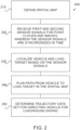
- Fig. 2 shows an example of a method 200.
- the method comprises several parts which may be performed independently from each other and/or in any order.
- the method can be used for localizing a vehicle, such as a load handling vehicle or the vehicle described in any of the examples herein, and the load target.
- parts 210, 220 and 230 described in the following, in particular in that order, may be used for the method for localizing the vehicle and the load target. Any of features described with reference to the vehicle 100 are applicable also in connection of the method 200 and any parts of it.
- the method may comprise obtaining 210, e.g. generating or receiving as described above, a spatial map describing a surrounding of the vehicle.
- the method may comprise receiving 220 first sensor signals from a first sensor system for generating point clouds of the surrounding of the vehicle and/or receiving second sensor signals from a second sensor system for generating images of the surrounding of the vehicle.
- the second sensor signals may be synchronized in time with the first sensor signals.
- the method may also comprise localizing 230 the vehicle and the load target in the spatial map based on the first sensor signals and the second sensor signals, for example in any of the ways described above.
- Localizing the load target in the spatial map thus comprises identifying the load target based on one or more images of the surrounding of the load handling vehicle generated by the second sensor system to obtain an identified load target on an identification image and determining the position of the load target in the spatial map by projecting one or more second point clouds of the surrounding of the load handling vehicle obtained from the first sensor signals to the identification image.
- the one or more second point clouds are synchronized in time with respect to the one or more images.
- the method may comprise planning 240 a path for the vehicle from the position and/or orientation of the vehicle in the spatial map to the position and/or orientation of the load target in the spatial map.
- the method may comprise determining 250 a trajectory data set for directing the vehicle along the path towards the load target for loading and/or unloading at the load target.
- the method may be performed in a cyclic manner.
- the disclosed solutions may be arranged for a continuous decision-making process for controlling the vehicle operating under uncertainty and large localization errors. This can allow driver-assisted automated and autonomous operation of the vehicle and its working unit(s). No off-board infrastructure to support the sustained function is necessarily required, i.e. any or all of the disclosed features may be arranged to be provided on-board the vehicle.
- the first and the second sensor system can be solely used to detect, classify and range objects (e.g. humans or containers). This can be done in three dimensions for a low cost.
- Absolute positioning means such as satellite navigation systems, may be optionally used to supplement the localization but it is noted that the present solution importantly allows localization in the spatial map and within its own coordinate system.
- the vehicle and the load target may be localized, for example, by solving the point cloud registration problem with the Iterative Closest Point (ICP) algorithm.
- the vehicle and the load target may be localized by a point-to-point variant of the Levenberg-Marquardt algorithm (LMA).
- LMA Levenberg-Marquardt algorithm
- M-estimators M-estimators
- robust loss functions for outlier filtering.
- the algebraic localization and load pose outputs from the LMA may be fused with ego-motion state of the vehicle, for example by a robust Kalman filter (KF) for continuous, high bandwidth estimates, which are suited for closed-loop control. This can be again motivated by the M-estimators and robust statistics.
- KF Kalman filter
- a path as a parametric curve, in particular a Bezier path/curve may be planned to the load target using the aforementioned position estimates. This allows the vehicle, and its working unit(s) to smoothly approach and latch onto the load while minimizing any misalignment.
- the path may be translated to a local trajectory, which can be cyclically planned, for example in the Frenet frame, for both time-synchronous coordinated control and reactive obstacle avoidance benefits.
- the local trajectory can be provided to describe the desired, kinematically feasible motion states in future, e.g. by some seconds, for high bandwidth feed-forward control of the working unit(s) of the vehicle, such as the actuator(s) (e.g. to a desired curvature, desired brake deceleration or desired drive torque).
- the solutions may be provided on a model-based design (MBD) toolchain for broad compliance with on-board computer hardware and high-integrity software standards, such as ISO 26262 and IEC 61508, allowing mixed-mode offering.
- MBD model-based design
- Fig. 3 shows an example localizing 300 the vehicle 100 and the load target 310, such as a container.
- the pose (i.e. position and/or orientation) of the vehicle and/or the load target may be determined. This can be done, e.g. by the controller, as soon as sensory information is available, e.g. from the first and the second sensor system.
- the path from the vehicle towards the load target may be planned.
- the path is planned in the spatial map so it need not be based on the absolute position or orientation of the vehicle or the load target. Instead, the solutions allow path planning from the best-known position and/or orientation of the vehicle towards the best-known position and/or orientation of the load target.
- the path can be planned while the vehicle is driving.
- the path can be planned even while the vehicle is not exactly on the path.
- the path can be planned to guarantee the smoothness of the path while the controller attempts to keep the vehicle on the path and correct for disturbance from unknown vehicle and environment properties.
- the solution allows improved smoothness and continuity in the path and corresponding trajectory for the vehicle, thereby allowing drive control for the vehicle in real-time, in particular for by-wire vehicles. This can be done despite considerably large changes in updated sensory data.
- the localization can be viewed in terms of three coordinate frames: a map frame 320, a vehicle frame 322 and a load target frame 324.
- the map frame is a coordinate frame for the spatial map, e.g. a Cartesian coordinate frame. While the vehicle frame may be centered in any location at the vehicle, e.g. at an origin of the first sensor system or at an origin of the working unit(s) (where the origin may be located at the position where the measurement or work is conducted from), the vehicle frame still moves with the vehicle 100. In contrast, the map frame may correspond to a substantially stationary ground truth, even if it is repeatedly updated due to the spatial map being updated, e.g. as the first control system provides further information of the surrounding of the vehicle to the controller.
- position and/or orientation of the vehicle may be estimated 330 within the map frame.
- position and/or orientation of the load target may be estimated 332 within the map frame.
- position and/or orientation of the load target may also be estimated 334 in relative manner, for example within the vehicle frame.
- the path 340 from the position and/or orientation of the vehicle to the position and/or orientation of the load target may be planned.
- the controller may be arranged to plan the path for the vehicle to arrive at the load target with a final position and/or orientation 342 to align with the load target for loading and/or unloading.
- the path may be repeatedly updated, even when the vehicle moves.
- the controller may provide a trajectory data set for a trajectory 344 of the vehicle to follow the path (illustrated in Fig. 3 as a solid line overlapping the dashed line of the path).
- the trajectory data set may be provided to a control unit of the vehicle for controlling the movement of the vehicle along the path, for example through the trajectory interface.
- the third sensor system may also be utilized for planning the path.
- the controller may be arranged to utilize the third sensor signals from the third sensor system for guiding the vehicle towards the path.
- the third sensor signals may be utilized to localize the vehicle when the first sensor signals are not available and/or with a greater frequency than the localization of the vehicle based on the first sensor signals.
- the path therefore does not need to be continuously updated but the third sensor signals may be utilized to return the vehicle towards the path when the vehicle strays from the path. This also allows mitigating fluctuations in control of the vehicle due to uncertainty in the measurement results of the sensor systems.
- the controller may track trajectory by correcting errors caused by noisy sensor outputs.
- the path may be updated with a frequency smaller than the trajectory, in which case the path and the trajectory may deviate from each other, in particular for obstacle avoidance.
- the controller may be arranged to generate a local trajectory data set for returning the vehicle to the path. This may be provided as an update to the trajectory data set and transmitted over the trajectory interface to the control unit of the vehicle.
- the third sensor system may comprise a vehicle motion state sensor, e.g. a vehicle speed sensor, such as an odometer.
- a vehicle motion state sensor e.g. a vehicle speed sensor, such as an odometer.
- This allows the third sensor signals to comprise a vehicle motion state, such as speed, for determining the position and/or orientation of the vehicle, e.g. by incremental changes to the position and/or orientation of the vehicle. This may be done, for example, by updating the initial position and/or orientation based on the vehicle motion state, such as speed and/or steering angle.
- the vehicle motion state for such a purpose may also be obtained from a FMCW LiDAR, such as a 4D coherent FMCW LiDAR.
- a FMCW LiDAR such as a 4D coherent FMCW LiDAR.
- the third sensor system may comprise a vehicle heading and/or heading rate sensor, such as a gyroscope and/or an inertial navigation system (INS).
- INS inertial navigation system
- the vehicle heading and/or heading rate for such a purpose may also be obtained from the FMCW LiDAR.
- the vehicle heading and/or heading rate may be obtained with a fixed sample time.
- the controller may be arranged to perform a fitting of one or more first point clouds of the surrounding of the vehicle obtained from the first sensor signals to the spatial map.
- a transformation such as a rigid body transformation may be used.
- the transformation may comprise or consist of one or more rotations and/or one or more translations. This allows a robust, scalable, and maintenance-free solution.
- the rigid body transformation may be obtained from a registration algorithm, such as ICP, which may be used iteratively.
- the localization allows determining the position and/or orientation of the load handling vehicle in the spatial map as the surrounding captured in the first sensor signals can be mapped to the spatial map.
- the localization may be performed utilizing the Levenberg-Marquardt algorithm (LMA).
- An observation model may be formulated as where R is a 3-by-3 rotation matrix and t is a 3-by-1 translation vector and x is a 3-by-1 point.
- the sum of the weighted squares of the errors between the observed and fitted/transformed data may be minimized as follows: This allows improved stability in comparison to standard least-squares method, in particular if there are outliers present in the 3D point data.
- Minimizing the above function for the parameter vector p can be used to solve unknowns such as heading, x and y coordinates of the vehicle or an object of the surrounding, such as the load target, given a set of 3D points. This can be well fitted for iterative optimizers, such as the LMA.
- the effect of outliers on p can be minimized by introducing a weighting function addressing the diagonal components W.
- the Welch function among the family of M-estimators may be used as the weighting function.
- the weighting may read as follows for the i'th component:
- parameter c allows determining the influence and it can be modified by geometrically decreasing its value in every LMA iteration.
- the controller may thus be arranged to estimate, for example using the LMA, the rigid body transformation that optimizes alignment of the spatial, which may be represented by a source point cloud (as represented by y with a caret in the equations), to the one or more point clouds, such as the observed (also "target") point cloud (as represented by y in the equations).
- a source point cloud as represented by y with a caret in the equations
- the one or more point clouds such as the observed (also "target") point cloud (as represented by y in the equations).
- the source point cloud may be chosen so that it best aligns the vehicle for latching onto the load in the spatial map.
- This alignment may be obtained, for example, by using a CAD model in combination with a LiDAR sensor model, empirically by recording the source point cloud prior to latching, or in an interactive manner by guiding the driver using the display, such as a touch screen.
- the error function may be repeatedly evaluated by removing outliers and redefining the point-to-point correspondences. This process can be iterated until a fixed number of iterations is reached which, given a limited size point clouds, can render the computational load deterministic and thereby convenient in real-time applications. The iteration can also be stopped before the fixed number of iterations is reached if the error function converges faster.
- the formulation may fundamentally be provided as a mathematical inverse problem, so the estimate p may be termed algebraic. Therefore, the uncertainties in p may be viewed as high-frequency perturbations in most cases of interest.
- the vehicle's (internal) state which may comprise the speed and/or heading/heading rate, can be provided as high-bandwidth quantities subject to a low-frequency drift if propagated in an open-loop over time. As indicated above, they may be obtained from odometry, inertial navigation or exteroceptive perception system.
- the vehicle may be localized using the third sensor signals by sensor fusion.
- a Kalman filter KF
- a wide variety of applicable sensor fusion methodologies are available, in particular since the algebraic estimates in p are complementary to the motion state of the vehicle (which may also be referred as the ego-vehicle).
- a conventional PI-type 2-input control design may be used.
- the pair of inputs comprises a motion state x and its derivative (a time-derivative being illustrated by a dot over each of the corresponding symbols) originating from different sensors or modalities.
- the filter can minimize the individual error sources of x and its derivative for smooth, low-latency and drift-free 1-DoF (degree of freedom) motion estimates.
- the filter dynamics can match with a high degree of accuracy the stationary KF design in the time domain.
- the PI-gains of the KF may be modified by applying the Welch function (as described above) on the residual, e.g. as with the LMA.
- the KF's gains can be tuned in real-time to accommodate variations in the observation and process noise but without the computationally involved Riccati equation and gain update calculation of the standard KF.
- the one or more second point clouds of the surrounding of the vehicle obtained from the first sensor signals may be projected to the identification image and the controller may be arranged accordingly.
- a projection matrix may be utilized.
- the one or more second point clouds of the surrounding of the vehicle obtained from the first sensor signals can be projected into the one or more images, in particular to the identification image.
- the matrix P may be used to identify each object's, such as the (identified) load target's points, which may be three dimensional points, contained within the image region.
- the localization e.g. with LMA as described above, may be progressively applied to the source point cloud, e.g. buffered 1 second in the past while in motion, with respect to the point cloud(s) from the first sensor signals (most) recently observed by the first sensor system. While initialized to zero, the propagation may start once the load target is identified for the first time.
- any drift in the progressive accumulation may be maintained at a minimum. This allows the calculus of the current lateral deviation and heading deviation of the (ego-)vehicle relative to the path without relying on an expensive absolute positioning system (e.g. DGPS) or infrastructure. This allows highly maneuverable and precise motion control.
- the third sensor signals may be used in the localization and mapping framework to bound any drift in the vehicle's internal motion states, e.g. with the LMA and/or KF as described above.
- the (rigid body) transformation between the source and target point cloud may be prone to errors.
- Such a scan can be left unregistered without any immediate impact on propagating the ego-motion state using third sensor signals, or KF. This can account for temporary failures in mapping while keeping an estimate of the (ego-)vehicle position and/or orientation always available.
- Utilizing the third sensor signals, or the sensor fusion allows continuous availability of the estimates for the position and/or orientation of the (ego-)vehicle and/or the object, such as the load target. This allows repeated or continuous path and/or trajectory planning. Repeated planning can be important, as the noise in the planning tends to reduce as a function of distance to the object, such as the load target.
- the vehicle may be a car-like vehicle with steering, such as a truck with a hooklift, which has non-holonomic dynamics.
- the vehicle cannot be commanded to create a lateral motion without steering and having velocity in the longitudinal direction. Therefore, the path may typically be planned so that starts from the vehicle and ends at the load target with a curve that allows the vehicle to smoothly engage the load target, e.g. by latching the working unit(s), such as the hooklift, onto the load target.
- Fig. 4 illustrates path planning 400 for loading and/or unloading, where the path 340 may be provided by the controller.
- the path may start (P1) from the vehicle 100, for example at the working unit(s) 110. It may start smoothly by its tangency aligned with the orientation, e.g. the longitudinal direction, of the vehicle and/or the working unit(s).
- the path may end (P4) at the load target, for example at a point where the working unit(s) may engage the load target for loading and/or unloading.
- the path may end with a straight-line segment to allow improved path following performance from the trajectory tracking controller.
- the path may consist of several segments which are aligned with each other so that the planned position, heading and curvature along the path remains continuous.
- the path may end smoothly by its tangency aligned with the load target, e.g. its longitudinal direction, for loading and/or unloading.
- a clothoid curve or a polynomial curve allows efficiently accommodating such geometrical constraints.
- a set of six or more control points may be used for the path.
- the path may include its start point (P1) as a control point.
- the path may include its end point (P4) as a control point.
- Two or more other points may be used on and/or off the path.
- a point (P2), such as a second point, may be used as a control point to define the direction of entering the path.
- a point such as a penultimate point, may be used as a control point to define the direction of exiting from the path.
- the aforementioned two points may thus also be off-path.
- two or more additional points may be located between the second point and the penultimate point.
- four or more additional points may be located between the second point and the penultimate point.
- the trajectory data set may be provided to have the vehicle move on the path with its heading aligned tangentially with the path.
- An instantaneous center of rotation (ICR) for the vehicle is illustrated in the figure with radius of rotation r.
- P(s) a Bezier path/curve
- the solution allows the controller to provide real-time trajectories for combined usage of steering and change in speed (i.e. braking and/or acceleration).
- a set of optimal solutions may be provided within which the best kinematically feasible solution is chosen to safely operate the vehicle. This can be carried out by connecting the (ego-)vehicle state with a set of terminal states, for example by using 4 th - or 5 th -order polynomial trajectories defined in the Frenet coordinate system or quintic Bezier paths/curves.
- the trajectory data set can be provided with input directly from the path planning. It may be tuned for desired speed and/or acceleration profiles depending on the distance of the vehicle and/or the working unit(s) to the load target. Because of the constraints, the resulting maneuvers may be considered predictable, precise, and comfortable at the same time. The solution also allows safe integration since maneuvers for evasive driving can be easily parameterized to account for the presence of static and/or dynamic obstacles.
- the path and/or trajectory to the load target may be visualized to a driver using a display.
- the driver may be provided control over the brake pedal while approaching the load target.
- the controller may be arranged for facilitating projection of an illustration of the load target from the spatial map on the display for visualization purposes. This adds to the safety and comfort of the driver, as the upcoming maneuvers are intuitive and predictable seconds upfront from the screen.
- the solution allows utilizing a robotic architecture. It can be based on commonly available perception sensors (e.g. LiDAR and camera).
- the first and the second sensor systems can be provided with exteroceptive sensors, which can render their measurements dependent on range and angle of view. This is particularly eminent taking into account the limited nonholonomic steering capabilities of the vehicle, in particular when the vehicle requires extended space for steering.
- the perception and decision-making solution disclosed can function with the best available estimation at any time, rendering it particularly effective for the non-holonomic vehicles.
- Fig. 5 illustrates trajectory deviation 500 according to an example. The deviations are exaggerated in the figure for clarity.
- One cycle of operation for the controller may be defined as taking place from one measurement of the first sensor system to the next.
- the length of a cycle may be constant but it may also be spuriously extended if, for some reason, the first sensor signals are not provided or cannot be used for the localization.
- deviations of the vehicle from the desired trajectory which may include deviations in position and/or orientation
- the next cycle can then accommodate the most recent updates of the first sensor system for the vehicle and/or any objects of the surrounding such as the load target. These can be accommodated in the spatial map and in the coordinate frame 320 thereof.
- the actual position and/or orientation of the vehicle 100 may differ from the planned position and/or orientation 510.
- the deviation may include a lateral deviation 512 and/or heading deviation 514 (the longitudinal dashed lines extending from the actual position and the planned position in the figure depict an actual heading and a planned heading for the vehicle so any angular deviation from these being parallel signifies a heading deviation.
- the controller may provide a response, e.g. an update to the trajectory data set, for guiding the vehicle towards the path 344 without necessarily updating the path.
- Fig. 6 shows an example 600 of dataflow and modules for the solution. Any or all the modules may be provided by the controller 120.
- the controller may be provided with an architecture for the localization which is model-based and the architecture can provide the localization of the (ego-)vehicle simultaneously with planning the path and providing the trajectory data set to the load target.
- the modular structure makes it straightforward to split the computation to different physical hardware with different cycle times depending on the application.
- the architecture can be built by tools generally available to a person skilled in the art for code generation and hardware agnostic implementation.
- the object recognition, or identifying the objects of the surrounding such as the load target is not explicitly shown in the figure. It can be provided utilizing massively parallel system-on-chip (SoC) based computing (e.g. GPU).
- SoC system-on-chip
- the vehicle estimator 610 facilitates localizing the vehicle, for example as described above, and it may be configured to utilize various inputs including, at least, the first sensor signals and, optionally, the third sensor signals. It then provides, as a first output 614, an estimation for the position and/or orientation of the vehicle. This may be delivered to a target estimator 620 and/or a path planner 630.
- the vehicle estimator 610 may also provide one or more additional outputs, in particular the spatial map 616 or an outline thereof, which may be provided, for example as a point cloud map, for the user interface and/or the target estimator.
- the target estimator 620 facilitates localizing the load target, for example as described above, and it may be configured to utilize any or all of the inputs 612 provided to the vehicle estimator.
- the inputs 622 to the target estimator include, at least, the second sensor signals and, optionally, an input for defining the image region.
- time signal such as the differential time may be provided.
- the target estimator provides, as a second output 624, an estimation for the position and/or orientation of the load target. This may be delivered to the path planner 630.
- the path planner 630 may utilize the estimation for the position and/or orientation of the vehicle and the estimation for the position and/or orientation of the load target to determine a path from the position and/or orientation of the vehicle to the position and/or orientation of the load target as a third output 632.
- the third output may be utilized, optionally together with other inputs 642 such as the third sensor signal to provide the trajectory data set 644.
- the other inputs 634 may be provided independently as an input to the trajectory planner so that the trajectory data set may be updated based on the other inputs 634 in particular the thirds sensor signals, even when updates from the third output are not available.
- the trajectory planner may also be provided with the capability to issue a stop command for the vehicle, for example in case of an emergency or an anticipated collision, or when a threshold time has passed since the last third output was provided to the trajectory planner.
- the stop command may be issued as a separate output 646 allowing it to be directly provided for vehicle control.
- the vehicle estimator 610 and the target estimator 620 can be founded upon the LMA and can, in any case, be provided computationally intensive, so they may be allocated with a priority for computational resources from the controller.
- the computational effort may be managed also by fixing the maximum number of iterations at the vehicle estimator and/or the target estimator, e.g. for the LMA, and fixing the size of the processed at the vehicle estimator and/or the target estimator, in particular by the LMA.
- the number of iterations may be limited below 100, for example to a maximum of 10-20.
- the point clouds may also be reduced in size, for example to below 1000 of points, such as 3D points, out of those sensed by the first sensor system per each scan, the number of which may well exceed a hundred thousand.
- the vehicle estimator 610 and/or the target estimator 620 can utilize the first sensor signals, for example by utilizing the LMA, to provide their respective outputs.
- the arrival of the first sensor signals can be event-based so providing the output dependent on the first sensor signals may become event-based.
- the vehicle estimator 610 and/or the target estimator 620 can utilize the third sensor signals, for example by means of sensor fusion.
- Kalman filtering may be utilized. This allows the first output 614 and/or the second output 624 to be provided with a frequency larger than the frequency of providing the first sensor signals, in a time-critical manner or even substantially in real-time, in particular in case of single-point failures in point cloud updates.
- An on-board solution may comprise the first and second sensor systems coupled to the controller, for example to the SoC thereof, for providing the first and second sensor signals to the SoC.
- the controller may be coupled to the trajectory interface, for example by means of a safe iPC, for bidirectional communication with the vehicle.
- the controller may also be coupled to one or more external servers, e.g. to a cloud computing system, e.g. for AI training and/or deployment. This allows data governance and management to be performed in the cloud computing system.
- the solution can be provided vehicle agnostic.
- the trajectory interface can be used as an abstraction layer, which mitigates the effect of vehicle-specific developments to the solution.
- the trajectory interface also allows clarifying the responsibilities and measures between the vehicle's by-wires layer and any robotic layer (s) of the working unit(s). This allows avoiding commercial and technical complications in safety analysis and system integration. This also allows monitoring performance of the vehicle for manoeuvres for the operation of the working unit(s) such as the hooklift (s).
- the presence of the trajectory interface for the vehicle by-wires control system is nevertheless not a necessary requirement for the solution to be deployed.
- Kinematic/dynamic equations and algorithms can be provided for the controller for converting trajectory to actuator commands for driveline, steering, brake, etc.
- the process units for the solution can be provided with various alternatives available to the skilled person.
- the subsystems and the algorithms, and generally all the blocks may be viewed to a large extent hardware-agnostic with the model-based design of the solution. Due to the use of coordinate systems for sensors and calibrated transformation between them, the solution can be made robust to changes in the properties of the first sensor system, e.g. the number or resolution of the sensors or the scanning frequency of the system.
- the solution can be utilized with a wide range of sensor systems available to the person skilled in the art.
- the solution's requirements for hardware can be made general enough that it matches the requirements of mapping and obstacle avoidance.
- the first sensor system such as a LiDAR system
- the second sensor system calculations and projections can be done after rectification of images. Therefore, different camera optics can be adapted for use.
- the controller may be provided with any intrinsic and/or extrinsic parameters of the sensor systems as input information and/or by calibration.
- the solution allows real-time smooth control commands.
- a commonly known drawback of traditional perception-based pose estimation and localization can be their jumpy behaviour.
- Such a characteristic in conjunction with the nonholonomic dynamic of the vehicle can create unnecessary steering commands which can cause wear and tear of components and can look irrational to a user.
- the solution allows overcoming such shortcomings in particular by optimal estimations in combination with sensor fusion together with smooth and well-behaved motion planning based on estimated values and parametrizing the output as a path generator in real-time.
- the solution can be offered as modules for a larger system or compiled into a stand-alone program on an independent process unit.
- the controller can be provided on an industrial PC dedicated to the load handling process or ADAS (Advanced Driver-Assistance Systems) modules.
- ADAS Advanced Driver-Assistance Systems
- An approach can be a combination of the solution with teleoperation approaches such that an on-site or off-site remote operator would command the vehicle thereby benefiting from short-term autonomy that removes the need for data-intensive synchronous communication.
- an autonomous load handling vehicle can be provided utilizing state-of-the-art vehicle capabilities using a digital interface towards its by-wires.
- the solution also allows providing Object and Event Detection and Response (OEDR).
- OEDR Object and Event Detection and Response
- the solution may be arranged to cover necessary verifications and failure detections and safety concerns related to planning, mapping, localization, and positioning under the topic of Dynamic Driving Tasks (DDT) and OEDR for L4 autonomous driving in accordance with SAE International's J3016.
- DDT Dynamic Driving Tasks
- OEDR for L4 autonomous driving in accordance with SAE International's J3016.
- monitoring of the object remaining stationary or consistency among estimated motion and force data can be used to detect anomalies and detect abnormal dynamics of the load pick and placement.
- the first sensor system comprising the FMCW LiDAR can provide instantaneous Doppler-based detection and removal of moving objects for the point clouds prior, e.g., pose estimation.
- the path may be planned and/or the trajectory data set determined from the position and/or orientation where the vehicle is assumed to be (in the spatial map), i.e. not necessary where the vehicle is.
- the path may be planned and/or the trajectory data set determined to the position and/or orientation where the load target is assumed to be (in the spatial map), i.e. not necessary where the load target is. This can be done whenever the first and/or third sensor signals are received by the controller.
- the position and/or orientation of the vehicle and/or the load target may be determined based on a coordinate frame in the spatial mapping, in contrast to a feature on an image.
- the solution also allows decoupling the planning from the control with all the associated benefits as described herein.
- the controller as described above may be implemented in software, hardware, application logic or a combination of software, hardware and application logic.
- the application logic, software or instruction set may be maintained on any one of various conventional computer-readable media.
- a "computer-readable medium” may be any media or means that can contain, store, communicate, propagate or transport the instructions for use by or in connection with an instruction execution system, apparatus, or device, such as a computer.
- a computer-readable medium may comprise a computer-readable storage medium that may be any media or means that can contain or store the instructions for use by or in connection with an instruction execution system, apparatus, or device, such as a computer.
- the examples can store information relating to various processes described herein.
- This information can be stored in one or more memories, such as a hard disk, optical disk, magneto-optical disk, RAM, and the like.
- One or more databases can store the information used to implement the embodiments.
- the databases can be organized using data structures (e.g., records, tables, arrays, fields, graphs, trees, lists, and the like) included in one or more memories or storage devices listed herein.
- the databases may be located on one or more devices comprising local and/or remote devices such as servers.
- the processes described with respect to the embodiments can include appropriate data structures for storing data collected and/or generated by the processes of the devices and subsystems of the embodiments in one or more databases.
- All or a portion of the embodiments can be implemented using one or more general purpose processors, microprocessors, digital signal processors, micro-controllers, and the like, programmed according to the teachings of the embodiments, as will be appreciated by those skilled in the computer and/or software art(s).
- Appropriate software can be readily prepared by programmers of ordinary skill based on the teachings of the embodiments, as will be appreciated by those skilled in the software art.
- the embodiments can be implemented by the preparation of application-specific integrated circuits or by interconnecting an appropriate network of conventional component circuits, as will be appreciated by those skilled in the electrical art(s).
- the embodiments are not limited to any specific combination of hardware and/or software.
Landscapes
- Engineering & Computer Science (AREA)
- Physics & Mathematics (AREA)
- Radar, Positioning & Navigation (AREA)
- Remote Sensing (AREA)
- General Physics & Mathematics (AREA)
- Automation & Control Theory (AREA)
- Aviation & Aerospace Engineering (AREA)
- Electromagnetism (AREA)
- Computer Networks & Wireless Communication (AREA)
- Transportation (AREA)
- Structural Engineering (AREA)
- Civil Engineering (AREA)
- Mechanical Engineering (AREA)
- Geology (AREA)
- Life Sciences & Earth Sciences (AREA)
- Computer Vision & Pattern Recognition (AREA)
- Theoretical Computer Science (AREA)
- Control Of Position, Course, Altitude, Or Attitude Of Moving Bodies (AREA)
- Closed-Circuit Television Systems (AREA)
Claims (14)
- Dispositif de commande (120) de manipulation de charge pour localiser un véhicule (100) de manipulation de charge et une cible de charge (310), le dispositif de commande de manipulation de charge étant agencé pour :- obtenir une carte spatiale décrivant un environnement (130) du véhicule de manipulation de charge ;- recevoir des premiers signaux de capteur en provenance d'un premier système (140) de capteur pour générer des nuages de points de l'environnement du véhicule de manipulation de charge ;- recevoir des deuxièmes signaux de capteur en provenance d'un deuxième système (142) de capteur pour générer des images de l'environnement du véhicule de manipulation de charge ; et- localiser le véhicule de manipulation de charge et la cible de charge dans la carte spatiale sur la base des premiers signaux de capteur et des deuxièmes signaux de capteur ;caractérisé en ce que les deuxièmes signaux de capteur sont synchronisés dans le temps avec les premiers signaux de capteur et la localisation de la cible de charge dans la carte spatiale comprend :- une identification de la cible de charge sur la base d'une ou plusieurs images de l'environnement du véhicule de manipulation de charge générées par le deuxième système de capteur pour obtenir une cible de charge identifiée sur une image d'identification ; et- une détermination de la position de la cible de charge dans la carte spatiale en projetant un ou plusieurs seconds nuages de points de l'environnement du véhicule de manipulation de charge obtenus à partir des premiers signaux de capteur sur l'image d'identification, les un ou plusieurs seconds nuages de points étant synchronisés dans le temps par rapport aux une ou plusieurs images.
- Dispositif de commande de manipulation de charge selon la revendication 1, dans lequel la localisation du véhicule de manipulation de charge comprend un ajustement d'un ou plusieurs premiers nuages de points de l'environnement du véhicule de manipulation de charge obtenus à partir des premiers signaux de capteur à la carte spatiale pour déterminer la position du véhicule de manipulation de charge dans la carte spatiale.
- Dispositif de commande de manipulation de charge selon la revendication 2, dans lequel les un ou plusieurs premiers nuages de points comprennent ou sont synchronisés dans le temps avec les un ou plusieurs seconds nuages de points.
- Dispositif de commande de manipulation de charge selon une quelconque revendication précédente, dans lequel l'identification de la cible de charge comprend une fourniture d'une région d'image délimitant la cible de charge identifiée dans l'image d'identification et les un ou plusieurs seconds nuages de points sont projetés sur l'image d'identification pour déterminer des points des un ou plusieurs seconds nuages de points correspondant à la cible de charge identifiée à l'intérieur de la région d'image.
- Dispositif de commande de manipulation de charge selon une quelconque revendication précédente, en outre agencé pour :- planifier un chemin (340) pour le véhicule de manipulation de charge depuis la position du véhicule de manipulation de charge dans la carte spatiale jusqu'à la position de la cible de charge dans la carte spatiale ; et- déterminer un ensemble de données de trajectoire pour diriger le véhicule de manipulation de charge le long du chemin vers la cible de charge pour un chargement et/ou déchargement au niveau de la cible de charge.
- Dispositif de commande de manipulation de charge selon une quelconque revendication précédente, agencé pour mettre à jour de façon répétée la carte spatiale sur la base des premiers signaux de capteur.
- Dispositif de commande de manipulation de charge selon une quelconque revendication précédente, agencé pour recevoir des troisièmes signaux de capteur à partir d'un troisième système (180) de capteur surveillant un état du véhicule de manipulation de charge et localiser le véhicule de manipulation de charge dans la carte spatiale en déterminant d'abord une position initiale du véhicule de manipulation de charge sur la base des premiers signaux de capteur et en mettant ensuite à jour la position initiale sur la base des troisièmes signaux de capteur.
- Dispositif de commande de manipulation de charge selon la revendication 7, lorsqu'elle est dépendante de la revendication 5, agencé pour mettre à jour de façon répétée avec une première fréquence la position du véhicule de manipulation de charge sur la base des troisièmes signaux de capteur et mettre à jour de façon répétée avec une seconde fréquence le chemin sur la base de la position du véhicule de manipulation de charge, dans lequel la première fréquence est supérieure ou égale à la seconde fréquence.
- Dispositif de commande de manipulation de charge selon une quelconque revendication précédente, agencé pour estimer la vitesse et/ou la vélocité du véhicule de manipulation de charge sur la base des premiers signaux de capteur et pour localiser le véhicule de manipulation de charge dans la carte spatiale sur la base de la vitesse et/ou de la vélocité estimée.
- Dispositif de commande de manipulation de charge selon une quelconque revendication précédente, agencé pour stocker la carte spatiale dans une mémoire devant être activée lorsque le véhicule de manipulation de charge arrive au niveau de l'environnement décrit par la carte spatiale.
- Dispositif de commande de manipulation de charge selon une quelconque revendication précédente, dans lequel la localisation du véhicule de manipulation de charge et de la cible de charge comprend une détermination d'une orientation du véhicule de manipulation de charge et d'une orientation de la cible de charge dans la carte spatiale.
- Ensemble d'équipement de travail pour un véhicule (100) de manipulation de charge, l'ensemble d'équipement de travail comprenant :- un dispositif de commande (120) de manipulation de charge selon l'une quelconque des revendications précédentes ;- le premier système (140) de capteur agencé pour surveiller un environnement (130) du véhicule de manipulation de charge ;- le deuxième système (142) de capteur agencé pour surveiller l'environnement du véhicule de manipulation de charge ;- un ou plusieurs actionneurs d'équipement de travail mobiles agencés pour faciliter un chargement et/ou déchargement du véhicule de manipulation de charge ; et- un dispositif de commande d'équipement de travail agencé pour commander le mouvement des actionneurs d'équipement de travail pendant le chargement et/ou le déchargement.
- Procédé (200) pour localiser un véhicule de manipulation de charge et une cible de charge, le procédé comprenant :- une obtention (210) d'une carte spatiale décrivant un environnement du véhicule de manipulation de charge ;- une réception (220) de premiers signaux de capteur en provenance d'un premier système de capteur pour générer des nuages de points de l'environnement du véhicule de manipulation de charge ;- une réception (220) de deuxièmes signaux de capteur en provenance d'un deuxième système de capteur pour générer des images de l'environnement du véhicule de manipulation de charge ; et- une localisation (230) du véhicule de manipulation de charge et de la cible de charge dans la carte spatiale sur la base des premiers signaux de capteur et des deuxièmes signaux de capteur ;caractérisé en ce que les deuxièmes signaux de capteur sont synchronisés dans le temps avec les premiers signaux de capteur et la localisation de la cible de charge dans la carte spatiale comprend :- une identification de la cible de charge sur la base d'une ou plusieurs images de l'environnement du véhicule de manipulation de charge générées par le deuxième système de capteur pour obtenir une cible de charge identifiée sur une image d'identification ; et- une détermination de la position de la cible de charge dans la carte spatiale en projetant un ou plusieurs seconds nuages de points de l'environnement du véhicule de manipulation de charge obtenus à partir des premiers signaux de capteur sur l'image d'identification, les un ou plusieurs seconds nuages de points étant synchronisés dans le temps par rapport aux une ou plusieurs images.
- Produit programme informatique comprenant des instructions qui, lorsqu'elles sont exécutées par un ordinateur, amènent l'ordinateur à mettre en oeuvre le procédé selon la revendication 13.
Priority Applications (9)
| Application Number | Priority Date | Filing Date | Title |
|---|---|---|---|
| EP22216292.7A EP4276564B1 (fr) | 2022-12-23 | 2022-12-23 | Calcul de position basé sur des capteurs d'image et de distance et procédé associé |
| ES22216292T ES3013898T3 (en) | 2022-12-23 | 2022-12-23 | Image and range sensor-based position controller and associated method |
| EP24206323.8A EP4468105B1 (fr) | 2022-12-23 | 2022-12-23 | Contrôleur de position basé sur un capteur d'image et de distance et procédé associé |
| EP25215874.6A EP4671900A1 (fr) | 2022-12-23 | 2022-12-23 | Contrôleur de position basé sur un capteur d'image et de distance et procédé associé |
| PL22216292.7T PL4276564T3 (pl) | 2022-12-23 | 2022-12-23 | Sterownik pozycji oparty na obrazie i czujniku zasięgu oraz powiązany sposób |
| CA3222242A CA3222242A1 (fr) | 2022-12-23 | 2023-12-06 | Commande et methode |
| AU2023278030A AU2023278030A1 (en) | 2022-12-23 | 2023-12-06 | Controller and method |
| US18/394,418 US20240210955A1 (en) | 2022-12-23 | 2023-12-22 | Controller and method |
| KR1020230189672A KR20240101479A (ko) | 2022-12-23 | 2023-12-22 | 제어기 및 방법 |
Applications Claiming Priority (1)
| Application Number | Priority Date | Filing Date | Title |
|---|---|---|---|
| EP22216292.7A EP4276564B1 (fr) | 2022-12-23 | 2022-12-23 | Calcul de position basé sur des capteurs d'image et de distance et procédé associé |
Related Child Applications (3)
| Application Number | Title | Priority Date | Filing Date |
|---|---|---|---|
| EP25215874.6A Division EP4671900A1 (fr) | 2022-12-23 | 2022-12-23 | Contrôleur de position basé sur un capteur d'image et de distance et procédé associé |
| EP24206323.8A Division-Into EP4468105B1 (fr) | 2022-12-23 | 2022-12-23 | Contrôleur de position basé sur un capteur d'image et de distance et procédé associé |
| EP24206323.8A Division EP4468105B1 (fr) | 2022-12-23 | 2022-12-23 | Contrôleur de position basé sur un capteur d'image et de distance et procédé associé |
Publications (3)
| Publication Number | Publication Date |
|---|---|
| EP4276564A1 EP4276564A1 (fr) | 2023-11-15 |
| EP4276564B1 true EP4276564B1 (fr) | 2024-12-18 |
| EP4276564C0 EP4276564C0 (fr) | 2024-12-18 |
Family
ID=84604024
Family Applications (3)
| Application Number | Title | Priority Date | Filing Date |
|---|---|---|---|
| EP24206323.8A Active EP4468105B1 (fr) | 2022-12-23 | 2022-12-23 | Contrôleur de position basé sur un capteur d'image et de distance et procédé associé |
| EP25215874.6A Pending EP4671900A1 (fr) | 2022-12-23 | 2022-12-23 | Contrôleur de position basé sur un capteur d'image et de distance et procédé associé |
| EP22216292.7A Active EP4276564B1 (fr) | 2022-12-23 | 2022-12-23 | Calcul de position basé sur des capteurs d'image et de distance et procédé associé |
Family Applications Before (2)
| Application Number | Title | Priority Date | Filing Date |
|---|---|---|---|
| EP24206323.8A Active EP4468105B1 (fr) | 2022-12-23 | 2022-12-23 | Contrôleur de position basé sur un capteur d'image et de distance et procédé associé |
| EP25215874.6A Pending EP4671900A1 (fr) | 2022-12-23 | 2022-12-23 | Contrôleur de position basé sur un capteur d'image et de distance et procédé associé |
Country Status (7)
| Country | Link |
|---|---|
| US (1) | US20240210955A1 (fr) |
| EP (3) | EP4468105B1 (fr) |
| KR (1) | KR20240101479A (fr) |
| AU (1) | AU2023278030A1 (fr) |
| CA (1) | CA3222242A1 (fr) |
| ES (1) | ES3013898T3 (fr) |
| PL (1) | PL4276564T3 (fr) |
Families Citing this family (10)
| Publication number | Priority date | Publication date | Assignee | Title |
|---|---|---|---|---|
| CN110114632B (zh) | 2016-11-30 | 2021-10-29 | 布莱克莫尔传感器和分析有限责任公司 | 用于对光学啁啾距离检测进行多普勒检测和多普勒校正的方法和系统 |
| US10422880B2 (en) | 2017-02-03 | 2019-09-24 | Blackmore Sensors and Analytics Inc. | Method and system for doppler detection and doppler correction of optical phase-encoded range detection |
| WO2019209727A1 (fr) * | 2018-04-23 | 2019-10-31 | Blackmore Sensors and Analytics Inc. | Procédé et système de commande de véhicule autonome utilisant des capteurs optiques doppler à plage cohérente |
| CN113260873A (zh) | 2019-01-04 | 2021-08-13 | 布莱克莫尔传感器和分析有限责任公司 | 带有具有折射分面的可旋转多边形偏转器的lidar设备 |
| US11822010B2 (en) | 2019-01-04 | 2023-11-21 | Blackmore Sensors & Analytics, Llc | LIDAR system |
| TWI827056B (zh) * | 2022-05-17 | 2023-12-21 | 中光電智能機器人股份有限公司 | 自動移動載具及其控制方法 |
| BE1032708B1 (nl) * | 2024-06-20 | 2026-01-28 | Smart Innovation Nv | Zelfrijdend voertuig, systeem en werkwijze voor laden en lossen |
| BE1032709B1 (nl) * | 2024-06-20 | 2026-01-27 | Smart Innovation Nv | Zelfrijdend voertuig, systeem en werkwijze voor het besturen van een zelfrijdend voertuig |
| EP4711322A1 (fr) * | 2024-09-16 | 2026-03-18 | TOYOTA MATERIAL HANDLING MANUFACTURING ITALY S.p.A | Conduite autonome ou assistée d'un chariot de manutention à l'aide d'une caméra et d'un lidar |
| CN120122670B (zh) * | 2025-05-13 | 2025-09-05 | 龙岩学院 | 一种基于混合导引的高精度堆垛机智能避障系统及方法 |
Family Cites Families (11)
| Publication number | Priority date | Publication date | Assignee | Title |
|---|---|---|---|---|
| US9772405B2 (en) * | 2014-10-06 | 2017-09-26 | The Boeing Company | Backfilling clouds of 3D coordinates |
| GB2571528A (en) * | 2018-02-28 | 2019-09-04 | Rolls Royce Plc | Controlling a robot in an environment |
| US10242273B1 (en) * | 2018-05-30 | 2019-03-26 | Lineage Logistics, LLC | Tracking vehicles in a warehouse environment |
| CN111238494B (zh) * | 2018-11-29 | 2022-07-19 | 财团法人工业技术研究院 | 载具、载具定位系统及载具定位方法 |
| WO2021199606A1 (fr) * | 2020-03-31 | 2021-10-07 | パイオニア株式会社 | Dispositif de traitement d'informations |
| US12098062B2 (en) * | 2020-07-15 | 2024-09-24 | Integrated Solutions for Systems, Inc. | Autonomous robotic cargo system |
| US20220144609A1 (en) * | 2020-11-06 | 2022-05-12 | Kabushiki Kaisha Toshiba | Autonomous mobile robot, transporter, autonomous mobile robot control method, and transporter control method |
| US11393227B1 (en) * | 2021-02-02 | 2022-07-19 | Sony Group Corporation | License plate recognition based vehicle control |
| KR102577907B1 (ko) * | 2021-03-02 | 2023-09-14 | 네이버랩스 주식회사 | 3차원 맵 생성 방법 및 시스템 |
| US20240160222A1 (en) * | 2021-03-03 | 2024-05-16 | Agency For Science, Technology And Research | Method and system for localizing a mobile robot |
| JP2024532865A (ja) * | 2021-08-20 | 2024-09-10 | オカド・イノベーション・リミテッド | 保管システムにおける荷役デバイスの運動学的状態の決定 |
-
2022
- 2022-12-23 EP EP24206323.8A patent/EP4468105B1/fr active Active
- 2022-12-23 EP EP25215874.6A patent/EP4671900A1/fr active Pending
- 2022-12-23 ES ES22216292T patent/ES3013898T3/es active Active
- 2022-12-23 PL PL22216292.7T patent/PL4276564T3/pl unknown
- 2022-12-23 EP EP22216292.7A patent/EP4276564B1/fr active Active
-
2023
- 2023-12-06 CA CA3222242A patent/CA3222242A1/fr active Pending
- 2023-12-06 AU AU2023278030A patent/AU2023278030A1/en active Pending
- 2023-12-22 US US18/394,418 patent/US20240210955A1/en active Pending
- 2023-12-22 KR KR1020230189672A patent/KR20240101479A/ko active Pending
Also Published As
| Publication number | Publication date |
|---|---|
| KR20240101479A (ko) | 2024-07-02 |
| ES3013898T3 (en) | 2025-04-15 |
| EP4276564C0 (fr) | 2024-12-18 |
| EP4468105C0 (fr) | 2026-02-04 |
| EP4468105A2 (fr) | 2024-11-27 |
| EP4276564A1 (fr) | 2023-11-15 |
| EP4671900A1 (fr) | 2025-12-31 |
| EP4468105B1 (fr) | 2026-02-04 |
| CA3222242A1 (fr) | 2024-06-23 |
| US20240210955A1 (en) | 2024-06-27 |
| PL4276564T3 (pl) | 2025-04-28 |
| EP4468105A3 (fr) | 2025-01-22 |
| AU2023278030A1 (en) | 2024-07-11 |
Similar Documents
| Publication | Publication Date | Title |
|---|---|---|
| EP4276564B1 (fr) | Calcul de position basé sur des capteurs d'image et de distance et procédé associé | |
| CN110262495B (zh) | 可实现移动机器人自主导航与精确定位的控制系统及方法 | |
| Gerdes et al. | Efficient autonomous navigation for planetary rovers with limited resources | |
| US8831880B2 (en) | Estimating positions of a device and at least one target in an environment | |
| WO2007143757A2 (fr) | Architecture logicielle permettant de parcourir à grande vitesse des itinéraires prescrits | |
| AU2009308192A1 (en) | Control and systems for autonomously driven vehicles | |
| US20140136046A1 (en) | Vehicle navigation | |
| US12157481B2 (en) | Systems and methods for hybrid open-loop and closed-loop path planning | |
| EP4194803A1 (fr) | Estimation d'angle d'attelage pour combinaison tracteur-remorque | |
| JP6949417B1 (ja) | 車両操縦システムと車両操縦方法 | |
| Cherubini et al. | Visual navigation with obstacle avoidance | |
| Lowrie et al. | The autonomous land vehicle (ALV) preliminary road-following demonstration | |
| CN119642820A (zh) | 一种机场无人驾驶行李牵引车路径规划方法及系统 | |
| Aref et al. | Position-based visual servoing for pallet picking by an articulated-frame-steering hydraulic mobile machine | |
| EP4377759B1 (fr) | Système et procédé de commande de mouvement d'un véhicule | |
| Aref et al. | A multistage controller with smooth switching for autonomous pallet picking | |
| Song et al. | Real-time localization measure and perception detection using multi-sensor fusion for Automated Guided Vehicles | |
| Leca et al. | Sensor-based obstacles avoidance using spiral controllers for an aircraft maintenance inspection robot | |
| Lu et al. | An autonomous vehicle platform for parcel delivery | |
| Jahoda et al. | Autonomous car chasing | |
| Shahna et al. | LiDAR-inertial SLAM-based navigation and safety-oriented AI-driven control system for skid-steer robots | |
| BR102023027351A2 (pt) | Controlador e método | |
| De San Bernabe et al. | Robots in manufacturing: Current technology trends | |
| IT202200022308A1 (it) | Pianificazione di traiettoria a bassa velocita' basata su un modello di controllo predittivo con evitamento di ostacoli dinamici in ambienti non strutturati | |
| Agarwal | Design and development of an affordable autonomous vehicle for bike lanes |
Legal Events
| Date | Code | Title | Description |
|---|---|---|---|
| PUAI | Public reference made under article 153(3) epc to a published international application that has entered the european phase |
Free format text: ORIGINAL CODE: 0009012 |
|
| STAA | Information on the status of an ep patent application or granted ep patent |
Free format text: STATUS: THE APPLICATION HAS BEEN PUBLISHED |
|
| AK | Designated contracting states |
Kind code of ref document: A1 Designated state(s): AL AT BE BG CH CY CZ DE DK EE ES FI FR GB GR HR HU IE IS IT LI LT LU LV MC ME MK MT NL NO PL PT RO RS SE SI SK SM TR |
|
| STAA | Information on the status of an ep patent application or granted ep patent |
Free format text: STATUS: REQUEST FOR EXAMINATION WAS MADE |
|
| 17P | Request for examination filed |
Effective date: 20240429 |
|
| RBV | Designated contracting states (corrected) |
Designated state(s): AL AT BE BG CH CY CZ DE DK EE ES FI FR GB GR HR HU IE IS IT LI LT LU LV MC ME MK MT NL NO PL PT RO RS SE SI SK SM TR |
|
| REG | Reference to a national code |
Ref country code: DE Free format text: PREVIOUS MAIN CLASS: G05D0001020000 Ipc: B66F0009070000 Ref country code: DE Ref legal event code: R079 Ref document number: 602022008823 Country of ref document: DE Free format text: PREVIOUS MAIN CLASS: G05D0001020000 Ipc: B66F0009070000 |
|
| GRAP | Despatch of communication of intention to grant a patent |
Free format text: ORIGINAL CODE: EPIDOSNIGR1 |
|
| STAA | Information on the status of an ep patent application or granted ep patent |
Free format text: STATUS: GRANT OF PATENT IS INTENDED |
|
| RIC1 | Information provided on ipc code assigned before grant |
Ipc: G05D 1/00 20060101ALI20240627BHEP Ipc: B66F 9/06 20060101ALI20240627BHEP Ipc: B66F 9/075 20060101ALI20240627BHEP Ipc: B66F 1/00 20060101ALI20240627BHEP Ipc: G01S 17/931 20200101ALI20240627BHEP Ipc: G01S 17/86 20200101ALI20240627BHEP Ipc: G01S 17/58 20060101ALI20240627BHEP Ipc: G01S 17/42 20060101ALI20240627BHEP Ipc: G01S 7/48 20060101ALI20240627BHEP Ipc: G01C 21/00 20060101ALI20240627BHEP Ipc: B66F 9/07 20060101AFI20240627BHEP |
|
| INTG | Intention to grant announced |
Effective date: 20240722 |
|
| RAP3 | Party data changed (applicant data changed or rights of an application transferred) |
Owner name: HIAB AB |
|
| GRAS | Grant fee paid |
Free format text: ORIGINAL CODE: EPIDOSNIGR3 |
|
| GRAA | (expected) grant |
Free format text: ORIGINAL CODE: 0009210 |
|
| STAA | Information on the status of an ep patent application or granted ep patent |
Free format text: STATUS: THE PATENT HAS BEEN GRANTED |
|
| AK | Designated contracting states |
Kind code of ref document: B1 Designated state(s): AL AT BE BG CH CY CZ DE DK EE ES FI FR GB GR HR HU IE IS IT LI LT LU LV MC ME MK MT NL NO PL PT RO RS SE SI SK SM TR |
|
| REG | Reference to a national code |
Ref country code: CH Ref legal event code: EP |
|
| REG | Reference to a national code |
Ref country code: DE Ref legal event code: R096 Ref document number: 602022008823 Country of ref document: DE |
|
| REG | Reference to a national code |
Ref country code: IE Ref legal event code: FG4D |
|
| U01 | Request for unitary effect filed |
Effective date: 20250116 |
|
| U07 | Unitary effect registered |
Designated state(s): AT BE BG DE DK EE FI FR IT LT LU LV MT NL PT RO SE SI Effective date: 20250122 |
|
| PG25 | Lapsed in a contracting state [announced via postgrant information from national office to epo] |
Ref country code: HR Free format text: LAPSE BECAUSE OF FAILURE TO SUBMIT A TRANSLATION OF THE DESCRIPTION OR TO PAY THE FEE WITHIN THE PRESCRIBED TIME-LIMIT Effective date: 20241218 |
|
| REG | Reference to a national code |
Ref country code: ES Ref legal event code: FG2A Ref document number: 3013898 Country of ref document: ES Kind code of ref document: T3 Effective date: 20250415 |
|
| PG25 | Lapsed in a contracting state [announced via postgrant information from national office to epo] |
Ref country code: GR Free format text: LAPSE BECAUSE OF FAILURE TO SUBMIT A TRANSLATION OF THE DESCRIPTION OR TO PAY THE FEE WITHIN THE PRESCRIBED TIME-LIMIT Effective date: 20250319 |
|
| PG25 | Lapsed in a contracting state [announced via postgrant information from national office to epo] |
Ref country code: RS Free format text: LAPSE BECAUSE OF FAILURE TO SUBMIT A TRANSLATION OF THE DESCRIPTION OR TO PAY THE FEE WITHIN THE PRESCRIBED TIME-LIMIT Effective date: 20250318 |
|
| U21 | Renewal fee for the european patent with unitary effect paid with additional fee |
Year of fee payment: 3 Effective date: 20250429 |
|
| PG25 | Lapsed in a contracting state [announced via postgrant information from national office to epo] |
Ref country code: SM Free format text: LAPSE BECAUSE OF FAILURE TO SUBMIT A TRANSLATION OF THE DESCRIPTION OR TO PAY THE FEE WITHIN THE PRESCRIBED TIME-LIMIT Effective date: 20241218 |
|
| PG25 | Lapsed in a contracting state [announced via postgrant information from national office to epo] |
Ref country code: IS Free format text: LAPSE BECAUSE OF FAILURE TO SUBMIT A TRANSLATION OF THE DESCRIPTION OR TO PAY THE FEE WITHIN THE PRESCRIBED TIME-LIMIT Effective date: 20250418 |
|
| PG25 | Lapsed in a contracting state [announced via postgrant information from national office to epo] |
Ref country code: SK Free format text: LAPSE BECAUSE OF FAILURE TO SUBMIT A TRANSLATION OF THE DESCRIPTION OR TO PAY THE FEE WITHIN THE PRESCRIBED TIME-LIMIT Effective date: 20241218 |
|
| PG25 | Lapsed in a contracting state [announced via postgrant information from national office to epo] |
Ref country code: MC Free format text: LAPSE BECAUSE OF FAILURE TO SUBMIT A TRANSLATION OF THE DESCRIPTION OR TO PAY THE FEE WITHIN THE PRESCRIBED TIME-LIMIT Effective date: 20241218 |
|
| PG25 | Lapsed in a contracting state [announced via postgrant information from national office to epo] |
Ref country code: IE Free format text: LAPSE BECAUSE OF NON-PAYMENT OF DUE FEES Effective date: 20241223 |
|
| PLBE | No opposition filed within time limit |
Free format text: ORIGINAL CODE: 0009261 |
|
| STAA | Information on the status of an ep patent application or granted ep patent |
Free format text: STATUS: NO OPPOSITION FILED WITHIN TIME LIMIT |
|
| 26N | No opposition filed |
Effective date: 20250919 |
|
| PGFP | Annual fee paid to national office [announced via postgrant information from national office to epo] |
Ref country code: NO Payment date: 20251218 Year of fee payment: 4 |
|
| PGFP | Annual fee paid to national office [announced via postgrant information from national office to epo] |
Ref country code: CZ Payment date: 20251215 Year of fee payment: 4 |
|
| PGFP | Annual fee paid to national office [announced via postgrant information from national office to epo] |
Ref country code: PL Payment date: 20251222 Year of fee payment: 4 |
|
| U20 | Renewal fee for the european patent with unitary effect paid |
Year of fee payment: 4 Effective date: 20251223 |
|
| PGFP | Annual fee paid to national office [announced via postgrant information from national office to epo] |
Ref country code: ES Payment date: 20260122 Year of fee payment: 4 |