EP2720019A1 - Transducteur de pression utilisant un diaphragme en céramique - Google Patents
Transducteur de pression utilisant un diaphragme en céramique Download PDFInfo
- Publication number
- EP2720019A1 EP2720019A1 EP13187201.2A EP13187201A EP2720019A1 EP 2720019 A1 EP2720019 A1 EP 2720019A1 EP 13187201 A EP13187201 A EP 13187201A EP 2720019 A1 EP2720019 A1 EP 2720019A1
- Authority
- EP
- European Patent Office
- Prior art keywords
- ceramic diaphragm
- pressure transducer
- base plate
- diaphragm
- strain gages
- Prior art date
- Legal status (The legal status is an assumption and is not a legal conclusion. Google has not performed a legal analysis and makes no representation as to the accuracy of the status listed.)
- Withdrawn
Links
- 239000000919 ceramic Substances 0.000 title claims abstract description 96
- 239000012790 adhesive layer Substances 0.000 claims abstract description 16
- 239000004020 conductor Substances 0.000 claims abstract description 9
- 239000011521 glass Substances 0.000 claims description 4
- 238000002844 melting Methods 0.000 claims description 3
- 238000004519 manufacturing process Methods 0.000 abstract description 25
- 238000012545 processing Methods 0.000 abstract description 7
- 238000000034 method Methods 0.000 description 9
- 230000008859 change Effects 0.000 description 8
- 238000005259 measurement Methods 0.000 description 6
- 239000000853 adhesive Substances 0.000 description 4
- 230000001070 adhesive effect Effects 0.000 description 4
- 230000008569 process Effects 0.000 description 4
- 239000003822 epoxy resin Substances 0.000 description 3
- 239000007789 gas Substances 0.000 description 3
- 239000007788 liquid Substances 0.000 description 3
- 229920000647 polyepoxide Polymers 0.000 description 3
- 229910000679 solder Inorganic materials 0.000 description 3
- 239000010409 thin film Substances 0.000 description 3
- 238000013022 venting Methods 0.000 description 3
- 230000006866 deterioration Effects 0.000 description 2
- 238000005516 engineering process Methods 0.000 description 2
- 239000010408 film Substances 0.000 description 2
- 239000010410 layer Substances 0.000 description 2
- 238000012986 modification Methods 0.000 description 2
- 230000004048 modification Effects 0.000 description 2
- 238000000059 patterning Methods 0.000 description 2
- 238000007639 printing Methods 0.000 description 2
- 230000008901 benefit Effects 0.000 description 1
- 238000009530 blood pressure measurement Methods 0.000 description 1
- 230000015556 catabolic process Effects 0.000 description 1
- 239000011248 coating agent Substances 0.000 description 1
- 238000000576 coating method Methods 0.000 description 1
- 238000010276 construction Methods 0.000 description 1
- 238000005260 corrosion Methods 0.000 description 1
- 238000006731 degradation reaction Methods 0.000 description 1
- 238000011161 development Methods 0.000 description 1
- 238000001035 drying Methods 0.000 description 1
- 230000000694 effects Effects 0.000 description 1
- 229910052737 gold Inorganic materials 0.000 description 1
- 230000007774 longterm Effects 0.000 description 1
- 239000000463 material Substances 0.000 description 1
- 238000010297 mechanical methods and process Methods 0.000 description 1
- 230000005226 mechanical processes and functions Effects 0.000 description 1
- 239000002184 metal Substances 0.000 description 1
- 229910052751 metal Inorganic materials 0.000 description 1
- 239000011241 protective layer Substances 0.000 description 1
- 230000009467 reduction Effects 0.000 description 1
- 238000012827 research and development Methods 0.000 description 1
- 230000004044 response Effects 0.000 description 1
- 238000007650 screen-printing Methods 0.000 description 1
- 238000007789 sealing Methods 0.000 description 1
- 229910052709 silver Inorganic materials 0.000 description 1
- 238000005245 sintering Methods 0.000 description 1
- 238000012360 testing method Methods 0.000 description 1
- 239000002341 toxic gas Substances 0.000 description 1
Images



Classifications
-
- G—PHYSICS
- G01—MEASURING; TESTING
- G01L—MEASURING FORCE, STRESS, TORQUE, WORK, MECHANICAL POWER, MECHANICAL EFFICIENCY, OR FLUID PRESSURE
- G01L9/00—Measuring steady of quasi-steady pressure of fluid or fluent solid material by electric or magnetic pressure-sensitive elements; Transmitting or indicating the displacement of mechanical pressure-sensitive elements, used to measure the steady or quasi-steady pressure of a fluid or fluent solid material, by electric or magnetic means
- G01L9/0041—Transmitting or indicating the displacement of flexible diaphragms
- G01L9/0042—Constructional details associated with semiconductive diaphragm sensors, e.g. etching, or constructional details of non-semiconductive diaphragms
- G01L9/0044—Constructional details of non-semiconductive diaphragms
-
- G—PHYSICS
- G01—MEASURING; TESTING
- G01L—MEASURING FORCE, STRESS, TORQUE, WORK, MECHANICAL POWER, MECHANICAL EFFICIENCY, OR FLUID PRESSURE
- G01L19/00—Details of, or accessories for, apparatus for measuring steady or quasi-steady pressure of a fluent medium insofar as such details or accessories are not special to particular types of pressure gauges
- G01L19/06—Means for preventing overload or deleterious influence of the measured medium on the measuring device or vice versa
- G01L19/0618—Overload protection
-
- G—PHYSICS
- G01—MEASURING; TESTING
- G01L—MEASURING FORCE, STRESS, TORQUE, WORK, MECHANICAL POWER, MECHANICAL EFFICIENCY, OR FLUID PRESSURE
- G01L9/00—Measuring steady of quasi-steady pressure of fluid or fluent solid material by electric or magnetic pressure-sensitive elements; Transmitting or indicating the displacement of mechanical pressure-sensitive elements, used to measure the steady or quasi-steady pressure of a fluid or fluent solid material, by electric or magnetic means
- G01L9/0041—Transmitting or indicating the displacement of flexible diaphragms
- G01L9/0051—Transmitting or indicating the displacement of flexible diaphragms using variations in ohmic resistance
- G01L9/0052—Transmitting or indicating the displacement of flexible diaphragms using variations in ohmic resistance of piezoresistive elements
- G01L9/0055—Transmitting or indicating the displacement of flexible diaphragms using variations in ohmic resistance of piezoresistive elements bonded on a diaphragm
Definitions
- the following description relates to a pressure transducer using a ceramic diaphragm, and more particularly, to a pressure transducer using a ceramic diaphragm, which is not easily damaged so that there is no risk of leakage of a target medium to be measured, having a superior mass-production capability and a reduced volume and enabling low-price by simplifying a flexible cable and a printed circuit board (PCB) to connect the transducer and a signal processing chip.
- PCB printed circuit board
- a pressure transducer is used for measuring, for example, a pressure of a vehicle engine, and a wide range of pressure in various fields, such as industrial fields and civil engineering fields, which require a high level of precision in measurement.
- the pressure transducer includes strain gages for pressure measurement.
- a strain gage may be categorized into an electrical strain gage that electrically measures the strain of an object and a mechanical strain gage that mechanically measures the strain.
- the electrical strain gage measures a deformation rate of an object from the change of an electrical resistance of the strain gage which is caused when the object deforms.
- the mechanical strain gage detects a slight change in distances between two points and measures a deformation rate of an object to be measured from the detected distance change. With the introduction of the strain gages, deformation of an object can be precisely measured, and it is possible to estimate stress from the measured deformation.
- a pressure transducer using a stainless diaphragm As a conventional pressure transducer, a pressure transducer using a stainless diaphragm (Korean Patent Registration No. 10-240012 ) is used.
- the fabricating processes of the stainless diaphragm for the conventional pressure transducer are complicated and a gage is attached manually, the manufacturing process is complicated and thus the manufacturing costs are increased.
- the gage if the gage is exposed to the air or to a medium (liquid or gas) to be measured, it is easy to corrode, which may result in deterioration of long-term stability or reliability of the gage.
- a metal thin film strain gage is broken, the entire pressure transducer needs to be replaced, and the stainless diaphragm is not suitable to measure a pressure of a corrosive gas and liquid.
- Korean Laid-Open Patent No. 2001-0105085 discloses a pressure transducer using a ceramic diaphragm that is formed to have thereon a high-resistance thick film or a thin film gage, which is air-tightly sealed by a ceramic cap or coated with a protective layer of a special insulating coating, whereby the pressure transducer can be used for both a gas and liquid and have superior anti-corrosion properties.
- the ceramic diaphragm 1 is made of ceramic, which may be damaged when excessive pressure is exerted thereon, and thus may cause a serious risk of leakage of a medium to be measured. Especially, if the medium is a toxic gas, the leakage of the medium may result in severe consequences.
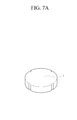
- the pressure transducers using a ceramic diaphragm use a circular-shaped ceramic diaphragm 1 as shown in FIGS. 7A and 7B , which is not effective for mass-production. Accordingly, the price of the pressure transducer is increased. Furthermore, since flexible cables (not shown) and a printed circuit board (PCB) (not shown) to connect the transducer and a signal processing chip have to be fabricated to fit the shape and size of the circular ceramic diaphragm 1, it causes an increase in volume and cost of the pressure transducer.
- PCB printed circuit board
- the following description relates to a pressure transducer using a ceramic diaphragm, which is not easily damaged, having a superior mass production and reduced volume and enabling low price.
- a pressure transducer using a ceramic diaphragm comprising: the ceramic diaphragm formed as a rectangular planar ceramic diaphragm and having a surface having formed thereon a pattern made of an electrically conductive material and strain gages; a base plate configured to face the surface of the ceramic diaphragm having formed thereon the pattern; and an adhesive layer configured to be formed along edges of a contacting surface of the ceramic diaphragm and the base plate so as to bond the ceramic diaphragm and the base plate and form a space for the strain gages.
- the base plate may have a thickness thicker than a thickness of the ceramic diaphragm and have a length shorter than a length of the ceramic diaphragm.
- a thickness of the adhesive layer may be smaller than 10 ⁇ m.
- the adhesive layer may be made of low-melting glass.
- FIG. 1 is a perspective view of a pressure transducer using a ceramic diaphragm according to an exemplary embodiment of the present invention.
- FIG. 2 is a cross-sectional view of the pressure transducer taken along line A-A' of FIG. 1 .
- the pressure transducer using a ceramic diaphragm includes a ceramic diaphragm 10, a base plate 20 facing the ceramic diaphragm 10, and an adhesive layer 40.
- the ceramic diaphragm is a rectangular planar ceramic diaphragm having a surface on which a pattern 50 (see FIG. 4 ) made of an electrically conductive material and strain gages 30 are formed.
- the base plate 20 faces the surface of the ceramic diaphragm on which the pattern 50 is formed, and the adhesive layer 40 is disposed along the edges of the facing surfaces of the ceramic diaphragm 10 and the base plate 20 to bond together the ceramic diaphragm 10 and the base plate 20 and to form a space for the strain gages 30.
- the ceramic diaphragm 10 and the base plate 20 are bonded by the adhesive layer 40 that is formed along the edges of the ceramic diaphragm 10 and the base plate 20.
- the adhesive layer 40 may be first formed either on the ceramic diaphragm 10 along the edges or on the base plate 20 along the edges, and then one can be attached to the other.
- the ceramic diaphragm 10 and the base plate 20 may be arranged facing each other at a predetermined distance and be bonded together by the adhesive layer 40 disposed along the edges of the facing ceramic diaphragm 10 and the base plate 20.
- a conventional pressure transducer illustrated in FIG. 6 has a limitation in reducing a gap G for a space between a base plate 3 and strain gages 2 when mechanically manufacturing the base plate 3. Accordingly, when an excessive pressure is applied to a ceramic diaphragm 1, causing the ceramic diaphragm 1 to be severely bent, the ceramic diaphragm 10 may not be able to contact the base plate 3 due to the wide gap G, and thereby being damaged. In a case where the ceramic diaphragm 10 is damaged or broken, a measurement target medium may leak through a venting hole 4.
- the pressure transducer using the ceramic diaphragm in accordance with the exemplary embodiment of the present invention uses an adhesive, the thickness of which is easy to control, so that it is possible to form the gap G to be equal to or narrower than 10 ⁇ m.
- the ceramic diaphragm 10 is able to contact the base plate 20, and thereby there is no risk of damaging the ceramic diaphragm 10 and the measurement target medium is prevented from leaking. Accordingly, the safety and reliability of the pressure transducer can be ensured.
- the thickness of the adhesive layer 40 may desirably but not necessarily be smaller than 10 ⁇ m.
- various types of adhesive may be used for the adhesive layer 40 as long as the adhesive does not affect the effects of the present invention, and examples of the adhesive suitable for use may include low-melting glass and glass frit.
- the ceramic diaphragm 10 and the base plate 20 are bonded by the adhesive layer 40, manufacturing time and process can be far more reduced as compared to the conventional mechanical processes of manufacturing the base plate 3 (see FIG. 6 ) to form the gap G for the strain gages 2 or of manufacturing a ceramic diaphragm 1 (see FIG. 5 ) for a pressure introducing portion.
- reference numeral 51 represents terminal solder pads, which are electrically connected to the pattern 50 formed on the ceramic diaphragm 10.
- Another important characteristic of the pressure transducer in accordance with the exemplary embodiment of the present invention is that only on a surface of the rectangular planar ceramic diaphragm 10, the pattern 50 formed of the electrically conductive material and the strain gages 30 are formed.
- a length l 20 of the base plate 20 is shorter than a length l 10 of the ceramic diaphragm 10 having the pattern formed thereon. That is, by configuring the ceramic diaphragm 10 to be longer than the base plate 20, the terminal solder pads 51 are disposed only on the ceramic diaphragm 10 to electrically connect the strain gages 20 and the pattern 60 formed of the electrically conductive material.
- patterns are formed on both a ceramic diaphragm and a base plate and thereafter, the ceramic diaphragm and the base plate are connected to each other by conductive epoxy resin, whereas in the exemplary embodiment of the present invention, the pattern formed of an electrically conductive material is disposed only on the ceramic diaphragm and thus it is possible to manufacture the pressure transducer without forming the pattern on the base plate and without using conductive epoxy resin. As a result, the manufacturing process can be simplified, and thereby significantly reduce the manufacturing cost.
- the shape of the base plate 20 may be a rectangular plane that corresponds to the rectangular planar ceramic diaphragm 10, and a thickness d20 of the base plate 20 may be thicker than a thickness d10 of the ceramic diaphragm 10.
- the length l 10 of the rectangular planar ceramic diaphragm 10 is longer than the length l 20 of the base plate 20.
- the difference between the lengths l 10 and l 20 may be only long enough for the terminal solder pads 51 to be formed as protruding from the base plate 20 and to function normally.
- the strain gages 30 may be formed by printing a paste layer of a conductive material, Au or Ag, and an electrical resistive material for forming the strain gage on the ceramic diaphragm 10 by use of screen printing, and then patterning the resulting layer with the drying and sintering process. Various well-known patterning methods may also be used.
- the pressure transducer converts a pressure into a resistance change of the strain gages 30, and it is important to convert the pressure into the effective change of the strain gages 30.
- a bent strain is imposed on the surface, and a small change which is applied to the back surface of the diaphragm 10 by the application of the pressure may cause a Wheatstone bridge consisting of four strain gages 30 to detect a small resistance change and to convert the detected small resistance change into an electrical signal.
- strain gages There are various patterns of strain gages to effectively detect a bent strain imposed on the diaphragm 10 that is fixed by the pressure.
- the strain gages 30 are formed by printing a thick film resistor.
- FIG. 4 is a top view of an example of the ceramic diaphragm for the pressure transducer, having a pattern 50 and four strain gages 30 formed thereon. Two of the strain gages 30 may be placed at a central portion of the diaphragm 10 that is most likely to be deformed in the central direction of a diaphragm circle 30-1 and the remaining two strain gages 30 may be placed over the edges of the diaphragm circle 30-1 which are most likely to be deformed in the circumferential direction of the diaphragm circle 30-1.
- the diaphragm 10 is made of ceramic to electrically isolate the strain gages 30 from the diaphragm 10.
- a resistance value of the strain gages 30 may be controlled between 100 ⁇ and 20 k ⁇ by adjusting a thickness of a thin film and lengths of the gages 30.
- FIG. 2 is a cross-sectional view of the pressure transducer taken along line A-A' of FIG. 1
- FIG. 3 is a cross-sectional view of a pressure transducer using a ceramic diaphragm according to another exemplary embodiment of the present invention.
- P and “P'” each represents a pressure introducing portion.
- a simplified flexible cable with a reduced volume is formed on a top of the base plate 20 and a signal processing integrated circuit (IC) chip is mounted on the flexible cable.
- the signal processing IC chip may be an application specific integrated circuit (ASIC).
- ASIC application specific integrated circuit
- the pressure transducer using the ceramic diaphragm shown in FIG. 2 is a transducer to measure a pressure with respect to an absolute vacuum.
- one portion of the diaphragm on which a pressure is applied is closed to form a reference vacuum chamber, and a pressure to be measured is introduced into the other portion.
- a degree of vacuum is an absolute reference for the transducer, and since it is not possible to adjust the absolute reference after the manufacturing, deterioration of the degree of vacuum due to leakage may cause the degradation of transducer performance. Thus, a leakage test or a vacuum-sealing process needs to be performed with great care.
- a base plate 20 having a plurality of lead lines (not shown) and the ceramic diaphragm 10 having the strain gages 30 formed thereon are attached together by the adhesive layer 40 to air-tight seal the strain gages 30.
- a gage pressure transducer as the pressure transducer using a ceramic diaphragm is to measure a gage pressure with reference to an ambient pressure, or a differential pressure transducer as the pressure transducer is to measure a difference between two pressures.
- a venting groove 21 is formed on the base plate.
- the ceramic diaphragm 10 and the base plate 20 may be desirably, but not necessarily, a rectangular plane, so that mass production of the pressure transducer and reduction of manufacturing costs can be achieved.
- a conventional pressure transducer since a conventional pressure transducer has a circular ceramic diaphragm and a circular base plate as shown in FIGS. 7A and 7B , its massive production is very difficult, resulting in an increase in the price of the pressure transducer.
- the pressure transducer using a ceramic diaphragm in accordance with the exemplary embodiment of the present invention includes the rectangular planar ceramic diaphragm and the rectangular planar base plate, and thus high mass production of the pressure transducer is feasible and thereby the price of the pressure transducer can be reduced.
- a pressure transducer using a ceramic diaphragm, which is not easily damaged so that there is no risk of leakage of a target medium to be measured, having a superior mass-production capability and a reduced volume and enabling low-price by simplifying a flexible cable and a printed circuit board (PCB) to connect the transducer and a signal processing chip.
- PCB printed circuit board
- the pressure transducer using a ceramic diaphragm may be applicable to measure, for example, a pressure of a vehicle engine, and a wide range of pressure in various fields, such as industrial fields and civil engineering fields, which require a high level of precision in measurement.
Landscapes
- Physics & Mathematics (AREA)
- General Physics & Mathematics (AREA)
- Chemical & Material Sciences (AREA)
- Analytical Chemistry (AREA)
- Measuring Fluid Pressure (AREA)
Applications Claiming Priority (2)
| Application Number | Priority Date | Filing Date | Title |
|---|---|---|---|
| US13/648,624 US8943896B2 (en) | 2012-10-10 | 2012-10-10 | Pressure transducer using ceramic diaphragm |
| KR1020120114992A KR20140046356A (ko) | 2012-10-10 | 2012-10-16 | 세라믹 다이어프램형 압력센서 |
Publications (1)
| Publication Number | Publication Date |
|---|---|
| EP2720019A1 true EP2720019A1 (fr) | 2014-04-16 |
Family
ID=49274543
Family Applications (1)
| Application Number | Title | Priority Date | Filing Date |
|---|---|---|---|
| EP13187201.2A Withdrawn EP2720019A1 (fr) | 2012-10-10 | 2013-10-03 | Transducteur de pression utilisant un diaphragme en céramique |
Country Status (2)
| Country | Link |
|---|---|
| EP (1) | EP2720019A1 (fr) |
| CN (1) | CN103728066A (fr) |
Cited By (1)
| Publication number | Priority date | Publication date | Assignee | Title |
|---|---|---|---|---|
| CN113340514A (zh) * | 2021-06-28 | 2021-09-03 | 东莞市华芯联科技有限公司 | 板载压力传感器的制备方法及其板载压力传感器 |
Families Citing this family (8)
| Publication number | Priority date | Publication date | Assignee | Title |
|---|---|---|---|---|
| CN107643132A (zh) * | 2016-07-22 | 2018-01-30 | 上海域丰传感仪器有限公司 | 一种密封压陶瓷平膜压力传感器 |
| DE112017007273T5 (de) * | 2017-04-07 | 2019-12-05 | Formosa Measurement Technology Inc. Ltd. | Differenzdrucksensor und Verfahren zu seiner Herstellung |
| CN108444621A (zh) * | 2018-05-28 | 2018-08-24 | 深圳研勤达科技有限公司 | 一种陶瓷电阻式压力传感器 |
| CN110542465A (zh) * | 2018-05-28 | 2019-12-06 | 深圳研勤达科技有限公司 | 一种陶瓷电阻式液位传感器 |
| CN109029826A (zh) * | 2018-08-27 | 2018-12-18 | 广州西博臣科技有限公司 | 一种抗高过载膜盒型陶瓷电阻型压力传感器 |
| CN112179310A (zh) * | 2019-07-02 | 2021-01-05 | 中兴通讯股份有限公司 | 印制电路板pcb的处理方法及装置 |
| CN113532704A (zh) * | 2020-04-14 | 2021-10-22 | 联合汽车电子有限公司 | 压力传感器 |
| CN112563145A (zh) * | 2020-11-26 | 2021-03-26 | 娄底市安地亚斯电子陶瓷有限公司 | 一种汽车制剂压力应变器陶瓷电路制备方法 |
Citations (9)
| Publication number | Priority date | Publication date | Assignee | Title |
|---|---|---|---|---|
| US4481497A (en) * | 1982-10-27 | 1984-11-06 | Kulite Semiconductor Products, Inc. | Transducer structures employing ceramic substrates and diaphragms |
| EP0831315A2 (fr) * | 1996-09-19 | 1998-03-25 | Fujikoki Corporation | Capteur de pression |
| DE19833712A1 (de) * | 1997-07-25 | 1999-01-28 | Denso Corp | Druckerfassungsvorrichtung mit Metallmembran |
| KR100240012B1 (ko) | 1997-05-23 | 2000-01-15 | 박재범 | 다이어 프램식 압력센서 |
| KR20010105085A (ko) | 2000-05-19 | 2001-11-28 | 김정희 | 세라믹 다이어프램형 압력센서의 제조방법 |
| US20040040382A1 (en) * | 2000-07-20 | 2004-03-04 | Thomas Peterson | Sensor usable in ultra pure and highly corrosive environments |
| DE102004011718A1 (de) * | 2003-03-13 | 2004-09-23 | Denso Corp., Kariya | Halbleiterdrucksensor |
| US20040200291A1 (en) * | 2003-04-11 | 2004-10-14 | Xunhu Dai | Multilayer ceramic pressure sensor |
| DE102010063065A1 (de) * | 2010-12-14 | 2012-06-14 | Endress + Hauser Gmbh + Co. Kg | Drucksensor und Verfahren zu dessen Herstellung+ |
Family Cites Families (3)
| Publication number | Priority date | Publication date | Assignee | Title |
|---|---|---|---|---|
| JPS6165126A (ja) * | 1984-09-06 | 1986-04-03 | Copal Denshi Kk | 圧力センサ |
| JPH08240500A (ja) * | 1995-03-01 | 1996-09-17 | Matsushita Electric Ind Co Ltd | 静電容量式圧力センサ及びその製造方法 |
| US5824909A (en) * | 1995-08-04 | 1998-10-20 | Ifm Electronic Gmbh | Pressure measuring sensor and apparatus having a seal between a housing and a pressure measuring cell |
-
2013
- 2013-10-03 EP EP13187201.2A patent/EP2720019A1/fr not_active Withdrawn
- 2013-10-10 CN CN201310470719.7A patent/CN103728066A/zh active Pending
Patent Citations (9)
| Publication number | Priority date | Publication date | Assignee | Title |
|---|---|---|---|---|
| US4481497A (en) * | 1982-10-27 | 1984-11-06 | Kulite Semiconductor Products, Inc. | Transducer structures employing ceramic substrates and diaphragms |
| EP0831315A2 (fr) * | 1996-09-19 | 1998-03-25 | Fujikoki Corporation | Capteur de pression |
| KR100240012B1 (ko) | 1997-05-23 | 2000-01-15 | 박재범 | 다이어 프램식 압력센서 |
| DE19833712A1 (de) * | 1997-07-25 | 1999-01-28 | Denso Corp | Druckerfassungsvorrichtung mit Metallmembran |
| KR20010105085A (ko) | 2000-05-19 | 2001-11-28 | 김정희 | 세라믹 다이어프램형 압력센서의 제조방법 |
| US20040040382A1 (en) * | 2000-07-20 | 2004-03-04 | Thomas Peterson | Sensor usable in ultra pure and highly corrosive environments |
| DE102004011718A1 (de) * | 2003-03-13 | 2004-09-23 | Denso Corp., Kariya | Halbleiterdrucksensor |
| US20040200291A1 (en) * | 2003-04-11 | 2004-10-14 | Xunhu Dai | Multilayer ceramic pressure sensor |
| DE102010063065A1 (de) * | 2010-12-14 | 2012-06-14 | Endress + Hauser Gmbh + Co. Kg | Drucksensor und Verfahren zu dessen Herstellung+ |
Cited By (1)
| Publication number | Priority date | Publication date | Assignee | Title |
|---|---|---|---|---|
| CN113340514A (zh) * | 2021-06-28 | 2021-09-03 | 东莞市华芯联科技有限公司 | 板载压力传感器的制备方法及其板载压力传感器 |
Also Published As
| Publication number | Publication date |
|---|---|
| CN103728066A (zh) | 2014-04-16 |
Similar Documents
| Publication | Publication Date | Title |
|---|---|---|
| EP2720019A1 (fr) | Transducteur de pression utilisant un diaphragme en céramique | |
| US4388668A (en) | Capacitive pressure transducer | |
| CN101356426B (zh) | 低成本高压传感器 | |
| EP1984718B1 (fr) | Capteur d'ultra haute pression basé sur une technologie des couches épaisses utilisant une construction de port et diaphragme intégrés | |
| CN115452235B (zh) | 压力传感器芯体及其制作方法 | |
| US7832269B2 (en) | Packaging multiple measurands into a combinational sensor system using elastomeric seals | |
| EP2270455B1 (fr) | Appareil de détection de force | |
| US10473546B2 (en) | Hermetic pressure sensor having a bending part | |
| US9541461B2 (en) | Ceramic pressure sensor and method for production thereof | |
| CN108458829B (zh) | 静电电容型压力传感器 | |
| US7882744B2 (en) | Flat planner pressure transducer | |
| CN111094923B (zh) | 陶瓷压力传感器 | |
| CN105466625A (zh) | 物理量测量装置 | |
| CN110174210B (zh) | 压力传感器及其封装方法 | |
| US8943896B2 (en) | Pressure transducer using ceramic diaphragm | |
| JPH11326088A (ja) | 圧力センサとその製造方法 | |
| WO2020228700A1 (fr) | Capteur et procédé de fabrication de capteur | |
| CN213714430U (zh) | 一种悬梁结构流量传感器 | |
| CN116472443A (zh) | 平面陶瓷压力传感器及相关制造方法 | |
| KR100330370B1 (ko) | 세라믹 다이어프램형 압력센서의 제조방법 | |
| CN110763393A (zh) | 压力传感器 | |
| CN110793706A (zh) | 压力传感器制作方法 | |
| CN114812881A (zh) | 柔性压力传感器及其制作方法 | |
| KR20150031995A (ko) | 압력 센서 장치 | |
| CN115165172A (zh) | 一种介质隔离的应变片式绝压压力传感器 |
Legal Events
| Date | Code | Title | Description |
|---|---|---|---|
| PUAI | Public reference made under article 153(3) epc to a published international application that has entered the european phase |
Free format text: ORIGINAL CODE: 0009012 |
|
| 17P | Request for examination filed |
Effective date: 20131004 |
|
| AK | Designated contracting states |
Kind code of ref document: A1 Designated state(s): AL AT BE BG CH CY CZ DE DK EE ES FI FR GB GR HR HU IE IS IT LI LT LU LV MC MK MT NL NO PL PT RO RS SE SI SK SM TR |
|
| AX | Request for extension of the european patent |
Extension state: BA ME |
|
| 17Q | First examination report despatched |
Effective date: 20140522 |
|
| GRAP | Despatch of communication of intention to grant a patent |
Free format text: ORIGINAL CODE: EPIDOSNIGR1 |
|
| INTG | Intention to grant announced |
Effective date: 20160511 |
|
| STAA | Information on the status of an ep patent application or granted ep patent |
Free format text: STATUS: THE APPLICATION IS DEEMED TO BE WITHDRAWN |
|
| 18D | Application deemed to be withdrawn |
Effective date: 20160922 |