EP2722015A1 - Clou intramédullaire - Google Patents
Clou intramédullaire Download PDFInfo
- Publication number
- EP2722015A1 EP2722015A1 EP12189297.0A EP12189297A EP2722015A1 EP 2722015 A1 EP2722015 A1 EP 2722015A1 EP 12189297 A EP12189297 A EP 12189297A EP 2722015 A1 EP2722015 A1 EP 2722015A1
- Authority
- EP
- European Patent Office
- Prior art keywords
- nail
- cone
- intramedullary nail
- bushing
- core
- Prior art date
- Legal status (The legal status is an assumption and is not a legal conclusion. Google has not performed a legal analysis and makes no representation as to the accuracy of the status listed.)
- Withdrawn
Links
- 210000001185 bone marrow Anatomy 0.000 title 1
- 210000000988 bone and bone Anatomy 0.000 claims description 24
- 229910000831 Steel Inorganic materials 0.000 claims description 5
- 238000003780 insertion Methods 0.000 claims description 5
- 230000037431 insertion Effects 0.000 claims description 5
- 239000010959 steel Substances 0.000 claims description 5
- 238000004804 winding Methods 0.000 claims description 5
- 238000006073 displacement reaction Methods 0.000 claims description 4
- 230000009467 reduction Effects 0.000 claims description 3
- 206010017076 Fracture Diseases 0.000 description 14
- 208000027418 Wounds and injury Diseases 0.000 description 12
- 206010052428 Wound Diseases 0.000 description 11
- 208000010392 Bone Fractures Diseases 0.000 description 10
- 230000007246 mechanism Effects 0.000 description 9
- 230000007704 transition Effects 0.000 description 7
- 230000006835 compression Effects 0.000 description 5
- 238000007906 compression Methods 0.000 description 5
- 230000008859 change Effects 0.000 description 4
- 230000035876 healing Effects 0.000 description 4
- 238000000034 method Methods 0.000 description 4
- 238000003466 welding Methods 0.000 description 4
- 238000004519 manufacturing process Methods 0.000 description 3
- 239000000463 material Substances 0.000 description 3
- 206010028980 Neoplasm Diseases 0.000 description 2
- RTAQQCXQSZGOHL-UHFFFAOYSA-N Titanium Chemical compound [Ti] RTAQQCXQSZGOHL-UHFFFAOYSA-N 0.000 description 2
- 201000011510 cancer Diseases 0.000 description 2
- 230000015556 catabolic process Effects 0.000 description 2
- 238000010276 construction Methods 0.000 description 2
- 230000001054 cortical effect Effects 0.000 description 2
- 238000006731 degradation reaction Methods 0.000 description 2
- 239000003814 drug Substances 0.000 description 2
- 229940079593 drug Drugs 0.000 description 2
- 210000003414 extremity Anatomy 0.000 description 2
- 238000003384 imaging method Methods 0.000 description 2
- 239000007943 implant Substances 0.000 description 2
- 230000006641 stabilisation Effects 0.000 description 2
- 238000011105 stabilization Methods 0.000 description 2
- 239000010936 titanium Substances 0.000 description 2
- 229910052719 titanium Inorganic materials 0.000 description 2
- 102000004506 Blood Proteins Human genes 0.000 description 1
- 108010017384 Blood Proteins Proteins 0.000 description 1
- 102000004190 Enzymes Human genes 0.000 description 1
- 108090000790 Enzymes Proteins 0.000 description 1
- 208000002847 Surgical Wound Diseases 0.000 description 1
- 230000006978 adaptation Effects 0.000 description 1
- 230000002009 allergenic effect Effects 0.000 description 1
- 230000004075 alteration Effects 0.000 description 1
- 210000004369 blood Anatomy 0.000 description 1
- 239000008280 blood Substances 0.000 description 1
- 210000001124 body fluid Anatomy 0.000 description 1
- 239000010839 body fluid Substances 0.000 description 1
- 210000002449 bone cell Anatomy 0.000 description 1
- 230000000711 cancerogenic effect Effects 0.000 description 1
- 231100000315 carcinogenic Toxicity 0.000 description 1
- 230000001413 cellular effect Effects 0.000 description 1
- 230000007797 corrosion Effects 0.000 description 1
- 238000005260 corrosion Methods 0.000 description 1
- 238000005520 cutting process Methods 0.000 description 1
- 230000006378 damage Effects 0.000 description 1
- 230000002950 deficient Effects 0.000 description 1
- 208000037265 diseases, disorders, signs and symptoms Diseases 0.000 description 1
- 208000035475 disorder Diseases 0.000 description 1
- 230000000694 effects Effects 0.000 description 1
- 230000003352 fibrogenic effect Effects 0.000 description 1
- 239000012634 fragment Substances 0.000 description 1
- 208000014674 injury Diseases 0.000 description 1
- 238000009434 installation Methods 0.000 description 1
- 230000003993 interaction Effects 0.000 description 1
- 238000002386 leaching Methods 0.000 description 1
- 229910052751 metal Inorganic materials 0.000 description 1
- 239000002184 metal Substances 0.000 description 1
- 230000017074 necrotic cell death Effects 0.000 description 1
- 230000002093 peripheral effect Effects 0.000 description 1
- 230000002980 postoperative effect Effects 0.000 description 1
- 230000002265 prevention Effects 0.000 description 1
- 230000008569 process Effects 0.000 description 1
- 239000012858 resilient material Substances 0.000 description 1
- 230000035939 shock Effects 0.000 description 1
- 239000002356 single layer Substances 0.000 description 1
- 230000000087 stabilizing effect Effects 0.000 description 1
- 229910000811 surgical stainless steel Inorganic materials 0.000 description 1
- 230000008685 targeting Effects 0.000 description 1
- 210000001694 thigh bone Anatomy 0.000 description 1
- 230000002885 thrombogenetic effect Effects 0.000 description 1
- 210000001519 tissue Anatomy 0.000 description 1
- 231100000331 toxic Toxicity 0.000 description 1
- 230000002588 toxic effect Effects 0.000 description 1
- 210000000623 ulna Anatomy 0.000 description 1
- 238000004018 waxing Methods 0.000 description 1
Images

Classifications
-
- A—HUMAN NECESSITIES
- A61—MEDICAL OR VETERINARY SCIENCE; HYGIENE
- A61B—DIAGNOSIS; SURGERY; IDENTIFICATION
- A61B17/00—Surgical instruments, devices or methods
- A61B17/56—Surgical instruments or methods for treatment of bones or joints; Devices specially adapted therefor
- A61B17/58—Surgical instruments or methods for treatment of bones or joints; Devices specially adapted therefor for osteosynthesis, e.g. bone plates, screws or setting implements
- A61B17/68—Internal fixation devices, including fasteners and spinal fixators, even if a part thereof projects from the skin
- A61B17/72—Intramedullary devices, e.g. pins or nails
- A61B17/7233—Intramedullary devices, e.g. pins or nails with special means of locking the nail to the bone
- A61B17/7258—Intramedullary devices, e.g. pins or nails with special means of locking the nail to the bone with laterally expanding parts, e.g. for gripping the bone
-
- A—HUMAN NECESSITIES
- A61—MEDICAL OR VETERINARY SCIENCE; HYGIENE
- A61B—DIAGNOSIS; SURGERY; IDENTIFICATION
- A61B17/00—Surgical instruments, devices or methods
- A61B17/56—Surgical instruments or methods for treatment of bones or joints; Devices specially adapted therefor
- A61B17/58—Surgical instruments or methods for treatment of bones or joints; Devices specially adapted therefor for osteosynthesis, e.g. bone plates, screws or setting implements
- A61B17/68—Internal fixation devices, including fasteners and spinal fixators, even if a part thereof projects from the skin
- A61B17/72—Intramedullary devices, e.g. pins or nails
- A61B17/7233—Intramedullary devices, e.g. pins or nails with special means of locking the nail to the bone
- A61B17/7258—Intramedullary devices, e.g. pins or nails with special means of locking the nail to the bone with laterally expanding parts, e.g. for gripping the bone
- A61B17/7275—Intramedullary devices, e.g. pins or nails with special means of locking the nail to the bone with laterally expanding parts, e.g. for gripping the bone with expanding cylindrical parts
Definitions
- the invention relates to an intramedullary nail, in particular for the closed reduction of a fracture of a long bone by insertion into a hole in the medullary cavity thereof.
- Such a helical spring can be designed at the ends with a device for fixing to the bone.
- a disadvantage of this known device is the indeterminacy of the position of the coil springs and the impossibility of rotation prevention as well as a fixation of individual fragments in the region of a fracture, since the spring properties of the coil springs can not hinder there.
- a nail system for intramedullary osteosynthesis in shaft fractures of all kinds is known DE 197 31 298 A1 comprising a tubular outer body with apertures from which hooks extend outwardly, which can be pivoted by operating an inner body to the outside, whereby the hooks should be able to create on the inner wall of a long bone.
- This nail system is extremely complex and has many components, but can in principle produce only point contacts with the inner surface of a long bone and this only in a narrow and identical length over the peripheral area.
- Simpler intramedullary nails for locking nailing are known, but their installation during an intervention can only be controlled by means of intraoperative X-ray imaging, which is extremely stressful not only for a patient, but especially for the OR staff because of the duration. Furthermore, such simple intramedullary nails must be secured by transverse screws in the bone, including in particular for long thigh bone, but also in the upper arm and lower leg bone elaborate targeting devices are required in order to be able to pinpoint such transverse screws with as little injury to the skin as possible. These surgical wounds, which are also to be introduced into a limb, must be laboriously treated after an operation but also after an operative removal of the transverse screws, which entails additional burdens for a patient.
- a head piece is arranged, on which the beginning of a band is fixed, which is wound around the nail core and which is attached at its end in the rear region to an outer sleeve and which upon rotation extends the radial contour of the intramedullary nail against its winding, wherein the nail core is attached to an inner sleeve, so that the inner sleeve is rotatable within the outer sleeve and movable in the longitudinal direction of the intramedullary nail.
- the object of the invention is therefore to provide an intramedullary nail available that does not change its set by the surgeon voltage and position even with axial pressure.
- the band is again wound around the nail core stronger, whereby the outer diameter of the intramedullary nail is reduced again, so that it can be easily pulled out of the hole or the medullary cavity.
- the inner bushing has an outer cone and the outer bush has an inner cone formed coaxially with the outer cone, the outer cone and inner cone tapering away from the headpiece, facing each other and being of the same configuration at least in sections, the surfaces of outer cone and inner cone being in a locking position pressed against each other and in unlocking no force and form fit between the outer cone and inner cone, an unwanted loosening of the fixation is avoided, since this the compression of the outer cone in the inner cone at a pressure on the bone in the longitudinal direction of the intramedullary nail reinforced but no movement because of the force and form fit more in this direction is possible. Furthermore, compression can be applied to the fracture gap of a long bone by the locking.
- an advantageous development of the invention provides that the inner bush at the head end remote end of the outer cone an adjoining part with outer cylinder and the outer bushing at the headpiece remote end of the inner cone have a subsequent part with inner cylinder, wherein the outer cylinder and inner cylinder are arranged coaxially and substantially free of play to each other , Thereby is a good and precise guidance of the inner bush, including nail core within the
- a further advantageous development of the invention provides that an end piece with an external thread is arranged at the head end remote from the nail core, wherein at least a part of the external thread is not covered by the outer sleeve in the radial direction. This can be screwed to the completion of the intramedullary nail a cap, which allows for a corresponding design of the individual parts a continuous transition from the outer sleeve to the end cap. It is preferred that the tail is a separate part of the nail core and is fixed relative to this in its position.
- a further advantageous embodiment of the invention provides that the displacement between unlocking and locking position is at most 10 mm, preferably at most 5 mm, more preferably at most 3 mm.
- Such a movement of the outer sleeve on the head piece is sufficient to create a compression, through which an improved bone healing can be achieved.
- Such compression is very useful in certain patient populations - such as cancer patients, cancer patients, drug addicts, alcoholics, and patients taking certain medicines.
- a further advantageous development of the invention provides that a circumferential groove is formed on the inner bush between the outer cone and the outer cylinder.
- a further advantageous embodiment of the invention provides that at the head end near the inner cone on the outer bush, a first stop surface and the head end of the outer cone on the inner sleeve a second stop surface are formed, both of which are oriented substantially perpendicular to the longitudinal direction of the intramedullary nail.
- a further advantageous development of the invention provides that the first stop surface is part of a separate from the outer sleeve guide member, wherein the guide member is fixedly connected to the outer sleeve.
- a further advantageous embodiment of the invention provides that the nail core is straight and firmly connected to the inner sleeve. This is a simple and secure way to connect these two parts together.
- the nail core has to be straight, since the head piece otherwise would make a circular movement with the rotation of the inner bush together with the nail core, which is not possible in a bone.
- a further advantageous development of the invention provides that the inner bush and / or the nail core are hollow. As a result, mass and thus weight is saved, which leads to a reduction in price due to the reduced material requirements and still sufficient stability of the intramedullary nail is given.
- a further advantageous development of the invention provides that the inner surface of the guide part of the outer bushing is cylindrical and the parts of the outer surface of the inner bush or of the nail core arranged therein are substantially free of play.
- an embodiment to emphasize, in the front of the intramedullary nail the beginning of another band - regularly an inner band - is set, which under the first band - regularly an outer band - order wound around the nail core and the end of which is fixed in the rear area of the intramedullary nail in a rotationally lockable manner around the inner bush.
- Such an (inner) band also increases the outer diameter of the intramedullary nail when it is rotated counter to its direction of winding or lays with its outer side against the inside of the first (outer) band and thus stabilizes the band and thus the entire intramedullary nail.
- This construction allows the realization of a high rigidity, which may correspond approximately to that of a thin tube.
- a plurality of inner or outer bands may be wound identically or in opposite directions and one or more around the nail core, wherein in a single-layer version of the inner bands these are wound directly around the nail core and in a single-ply embodiment the outer bands are wound around the inner bands.
- the radial outer surfaces of the inner band and the radially inner surfaces of the outer band are designed to be rough as mutual functional surfaces, so that the common contact surfaces of the bands stabilize points of an intramedullary nail inserted into a throughbore of a bone in the form of a frictional and frictional engagement Create connection. As a result, the stability of the intramedullary nail is further increased.
- the nail core is hollow over its entire length and pass through a sleeve and / or a shaft, so that the beginning of an inner and / or outer band can be fixed at the front region of the head piece of the intramedullary nail, wherein the rear end of the intramedullary nail this can be unwound and clamped from behind against its direction of rotation via a correspondingly formed locking mechanism.
- the subject nail core is completely reduced here except for a part in the locking mechanism, or is replaced by a free air space.
- Such a version allows an outward force-free clamping of the intramedullary nail, as in all other versions, without mechanical restoring forces would have to be absorbed by a bone or introduced into this.
- An inventive development of the intramedullary nail has about two outer bands of which one of the front portion of the intramedullary nail and from the rear of the intramedullary nail are rotatable, so that an optimal adaptation of the respective band on both sides of a medullary cavity trumpet wise expanding medullary canal and thus a optimal lateral cortical support is possible.
- the intramedullary nail can be formed straight or curved as needed or be plastically bendable according to the required spatial form.
- the nail core of an intramedullary nail can advantageously be designed in several parts, so that these parts can rotate against each other. This greatly enhances the possibilities for constructive design.
- two bands wound against each other are connected to each other at their front ends or a band from the outset in one piece and wound from its front end in opposite directions around the nail, so that the nail core can be formed shortened and only extends to a portion in the direction of the front end of the intramedullary nail.
- the intramedullary nail may be thinner in such a configuration than in continuous nail core.
- the nail core is even reduced to the locking mechanism, which quasi in the installed state, a stable rigid mesh grid remains as an intramedullary nail, resulting in an enormous saving of material.
- Such an embodiment is particularly suitable for small long bones - such as ulna and radius.
- a further advantageous embodiment of the invention provides that the intramedullary nail Steel exists. Due to the lower biocompatibility of steel compared to titanium, ingrowth is reduced to a minimum. Steel is not thrombogenic, toxic, allergenic, fibrogenic or carcinogenic. There is no degradation of cellular elements, no alteration to plasma proteins and enzymes, and no tissue necrosis. Steel is corrosion resistant, as there is no ionization of metallic atoms, resistant to degradation and leaching on contact with blood or body fluid. There is no ingrowth of osteoblast-like bone cells due to the mechanical structuring of the implant surface, and the physicochemical properties of the surface material can be adjusted, thus encapsulating the implant rather than waxing in and ensuring easy metal removal.
- Also contemplated by the present invention is the use of the intramedullary nail described herein to apply a compression pressure to a fracture site in a long bone.
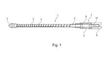
- the intramedullary nail 1 consists of a nail core 2, around its head piece 5, an inner band 4 and an outer band 3 are wound in opposite directions to each other, wherein the front ends of the bands 3, 4 are arranged stationary about a laser welding process on the head piece 5 ,
- the nail core 2 has at its head end close to a smaller diameter and is there inserted into the head piece 5 and fixedly connected to this - for example by welding.
- the ends of the bands 3, 4 are arranged on an outer bushing 8 and an inner bushing 9 of the locking mechanism 7 and there For example, also welded by means of a laser.
- the oppositely wound bands 3, 4 overlap at contact surfaces, wherein the mutually facing surfaces of the bands 3, 4 are formed so that there is a frictional fixation, which stabilizes the entire intramedullary nail 1. This results in an improved fixation of a fracture.
- FIG. 1 illustrated embodiment of the outer band 3 has turns, which have a smaller width in the region of the head piece 5 than in the region of the outer bushing 8.
- An end piece 14 is fixedly connected to the head piece remote end of the nail core 2, for example by welding. This will be locked in the locked state in FIG. 1 is shown and in FIG. 3 will be explained in more detail, a cap 6 screwed, the function will be explained in more detail below.
- FIGS. 2 and 3 are longitudinal sections through the intramedullary nail 1 of FIG. 1 shown, wherein the bands 3, 4 are not shown for reasons of clarity.
- the innovation of the intramedullary nail 1 according to the invention can be seen in its locking mechanism 7.
- the with the outer band 3 (see FIG. 1 ) connected outer socket 8 is formed in two parts.
- a guide member 19 in the FIGS. 2 and 3 this is the left part of the outer sleeve 8) connected to a main part 23.
- the main part 23 has, starting from the weld 22 to the right, an inner surface in the form of an inner cone 11, which tapers to the right.
- one piece is followed by a region whose surface has the shape of an inner cylinder 13.
- the diameter of the inner cylinder 13 is equal to the (smallest) diameter of the inner cone 11 at its right end.
- Inner cylinder 13 and inner cone 11 are aligned coaxially along the central axis of the nail core. 2
- the guide member 19 is formed in its weld region remote area as a cylinder which is arranged coaxially with the inner cylinder 13 and inner cone 11, the inner surface of the 20th In the region of the weld 22, the guide member 19 therefore has a shoulder which is perpendicular to the longitudinal axis of the nail core 2 and over which it is connected to the Main part 23 is welded. As a result, a first stop surface 17 is formed in the region of the shoulder, which extends perpendicular to the longitudinal axis of the nail core 2.
- the inner sleeve 7 is slidably disposed along the longitudinal axis of the nail core 2 within the outer sleeve 8. Although it is the nail core 2 about its longitudinal axis - a sliding bearing comparable - rotatable, but not along this axis to him displaced. This is achieved in that the diameter of the nail core 2 is lower at the head end remote than in its central portion, whereby a stop is formed, via which the nail core 2 abuts the headpiece near end of the inner sleeve 9; At the same time, a further stop for the nail core 2 with respect to the inner bushing 9 is formed at the head end remote end of the inner bush 9 by the fixedly connected to the nail core 2 end piece 14.
- the cylindrical outer surface 21 is dimensioned so that it runs just backlash in the cylindrical inner surface 20 of the guide member 19 of the outer sleeve 8.
- the outer cylinder 12 is dimensioned so that it runs just backlash in the inner cylinder of the main part 23 of the outer sleeve 8.
- the intermediate region of the outer cone 10 is shorter in the direction of the longitudinal axis of the nail core 2 than the inner cone 11 of the outer bushing 8.
- a circumferential groove 16 is formed in the transition region between outer cone 10 and outer cylinder 12.
- the diameter of the outer cone (its smallest) is slightly larger than that of the inner cone 11 of the outer sleeve 8 at its transition to the inner cylinder 13 Groove 16 in this transition region is removed from the manufacturing needs there formed burr.
- the opening angle of the outer cone 10 is the same as that of the inner cone 11 of the outer sleeve 8.
- the inner sleeve 9 has a perpendicular to the longitudinal axis of the nail core 2 second stop surface 18, which is smaller than the first Stop surface 17 at the headpiece remote end of the guide member 19 of the outer sleeve.
- the end piece 14 has an external thread 15 at its head end remote end.
- Outer cylinder 12, outer cone 10 and outer surface 21 of the inner sleeve 9 are arranged coaxially with one another and also coaxially with the corresponding parts of the outer bushing 8.
- the inner sleeve 9 can move over a certain length within the outer sleeve 8. The two extremes of this movement are in the FIGS. 2 and 3 shown.
- FIG. 2 represents intramedullary nail 1 in its unlocked state as it exists before and during insertion into the bone.
- the inner bushing 9 is arranged in the outer bush 8, that its second abutment surface 18 abuts against the first stop surface 17 of the outer bushing 8.
- the outer cone 10 of the inner bush 9 does not touch the inner cone 11 of the outer bushing 8.
- the inner bushing 9 can thus freely - except for the bands 3, 4, which complicate this - are rotated within the outer bushing 8 about the longitudinal axis of the nail core 2.
- the inner bushing 9 is rotated in the outer bushing 8 about the longitudinal axis of the nail core 2, so that a widening of the bands 3, 4 takes place.
- the bands 3, 4 are preferably made of resilient material, such as surgical steel, titanium or body-friendly plastic. This allows the desired properties of the intramedullary nail 1 with regard to the required Contact force as well as the nature and the course of the deformation, advantageously set optimally first from the front of the intramedullary nail 1 on the medullary waist to re-expanding end of a medullary cavity.
- the inner band 4 and / or the outer band 3 are formed differently broad or thick in different regions of the nail core 2 (see FIG.
- the inner band 4 and / or the outer band 3 are differently elastically biased in different areas of the nail core 2. It is also conceivable that, for example, the outer band 3 over its entire length or at least partially, viewed from the head piece 5, has a continuously changing cross-section, in particular an increasing width, over approximately the first 2/3 of its length (see FIG. 1 ) to fulfill the required function.
- Such an advantageous construction also makes it possible, in non-prestressed bands 3, 4, that the outer band 3 when turning against the direction of rotation initially applies in the region of the head piece 5 of the intramedullary nail 1 to the inner contour of a bone and only when further turning on first in middle region of the medullary waist of a long bone and then in the end of the intramedullary nail 1 to the re-expanding area of the medullary space applies.
- the intramedullary nail 1 is transferred to its locked state, as it is in FIG. 3 is shown.
- the outer sleeve 8 is moved with a suitable mounting tool in the direction of the head piece 5 until a clamping fit of the outer cone 10 of the inner sleeve 9 is given to the inner cone 11 of the outer sleeve 8. This is already achieved after a displacement of 3 mm.
- this locked state a further rotation of the inner sleeve 9 in the outer sleeve 8 as well as an axial displacement of the parts to each other is prevented.
- the intramedullary nail 1 is immovably fixed in the bone.
Landscapes
- Health & Medical Sciences (AREA)
- Orthopedic Medicine & Surgery (AREA)
- Surgery (AREA)
- Life Sciences & Earth Sciences (AREA)
- Heart & Thoracic Surgery (AREA)
- Nuclear Medicine, Radiotherapy & Molecular Imaging (AREA)
- Engineering & Computer Science (AREA)
- Biomedical Technology (AREA)
- Neurology (AREA)
- Medical Informatics (AREA)
- Molecular Biology (AREA)
- Animal Behavior & Ethology (AREA)
- General Health & Medical Sciences (AREA)
- Public Health (AREA)
- Veterinary Medicine (AREA)
- Surgical Instruments (AREA)
Priority Applications (2)
| Application Number | Priority Date | Filing Date | Title |
|---|---|---|---|
| EP12189297.0A EP2722015A1 (fr) | 2012-10-19 | 2012-10-19 | Clou intramédullaire |
| PCT/EP2013/071833 WO2014060576A1 (fr) | 2012-10-19 | 2013-10-18 | Clou intramédullaire |
Applications Claiming Priority (1)
| Application Number | Priority Date | Filing Date | Title |
|---|---|---|---|
| EP12189297.0A EP2722015A1 (fr) | 2012-10-19 | 2012-10-19 | Clou intramédullaire |
Publications (1)
| Publication Number | Publication Date |
|---|---|
| EP2722015A1 true EP2722015A1 (fr) | 2014-04-23 |
Family
ID=47172338
Family Applications (1)
| Application Number | Title | Priority Date | Filing Date |
|---|---|---|---|
| EP12189297.0A Withdrawn EP2722015A1 (fr) | 2012-10-19 | 2012-10-19 | Clou intramédullaire |
Country Status (2)
| Country | Link |
|---|---|
| EP (1) | EP2722015A1 (fr) |
| WO (1) | WO2014060576A1 (fr) |
Families Citing this family (11)
| Publication number | Priority date | Publication date | Assignee | Title |
|---|---|---|---|---|
| US10499960B2 (en) | 2015-07-13 | 2019-12-10 | IntraFuse, LLC | Method of bone fixation |
| US10136929B2 (en) | 2015-07-13 | 2018-11-27 | IntraFuse, LLC | Flexible bone implant |
| US10154863B2 (en) | 2015-07-13 | 2018-12-18 | IntraFuse, LLC | Flexible bone screw |
| US10485595B2 (en) | 2015-07-13 | 2019-11-26 | IntraFuse, LLC | Flexible bone screw |
| DE102021129927A1 (de) | 2021-11-16 | 2023-05-17 | Jabez Medical GmbH & Co. KG | Zweiteiliger Marknagel sowie Nagelkern hierfür |
| DE202021106260U1 (de) | 2021-11-16 | 2023-02-27 | Jabez Medical GmbH & Co. KG | Zweiteiliger Marknagel sowie Nagelkern hierfür |
| DE202022104343U1 (de) | 2022-07-30 | 2023-11-07 | Jabez Medical GmbH & Co. KG | Vorrichtung zum Betätigen eines Marknagels, umfassend ein Gewindeelement zum Anschluss eines Marknagels |
| DE102022119168A1 (de) | 2022-07-30 | 2024-02-01 | Jabez Medical GmbH & Co. KG | Vorrichtung zum Betätigen eines Marknagels, umfassend ein Adapterstück, Set zur Bereitstellung einer solchen Vorrichtung, Adapterstück, sowie Adapterset |
| DE202022104342U1 (de) | 2022-07-30 | 2023-11-07 | Jabez Medical GmbH & Co. KG | Vorrichtung zum Betätigen eines Marknagels, umfassend ein Adapterstück, Set zur Bereitstellung einer solchen Vorrichtung, Adapterstück, sowie Adapterset |
| DE102022119169A1 (de) | 2022-07-30 | 2024-02-01 | Jabez Medical GmbH & Co. KG | Vorrichtung zum Betätigen eines Marknagels, umfassend ein Gewindeelement zum Anschluss eines Marknagels |
| CN119896526B (zh) * | 2024-12-19 | 2025-07-25 | 中国人民解放军总医院第四医学中心 | 一种套筒组合式拉力加压内固定螺钉 |
Citations (3)
| Publication number | Priority date | Publication date | Assignee | Title |
|---|---|---|---|---|
| DE3835682A1 (de) | 1988-10-20 | 1990-04-26 | Labitzke Reiner Prof Dr Med Ha | Vorrichtung zur stabilisierung von roehrenknochenbruechen sowie von gelenken |
| DE19731298A1 (de) | 1996-12-30 | 1999-11-18 | Basheir Madhoon | Nagelsystem für die intramedulläre Osteosynthese bei Schaftfrakturen aller Art und Totalendprothesen |
| EP1827272B1 (fr) | 2004-12-23 | 2008-04-02 | Zielsdorf, Michael | Clou intramédullaire |
-
2012
- 2012-10-19 EP EP12189297.0A patent/EP2722015A1/fr not_active Withdrawn
-
2013
- 2013-10-18 WO PCT/EP2013/071833 patent/WO2014060576A1/fr not_active Ceased
Patent Citations (3)
| Publication number | Priority date | Publication date | Assignee | Title |
|---|---|---|---|---|
| DE3835682A1 (de) | 1988-10-20 | 1990-04-26 | Labitzke Reiner Prof Dr Med Ha | Vorrichtung zur stabilisierung von roehrenknochenbruechen sowie von gelenken |
| DE19731298A1 (de) | 1996-12-30 | 1999-11-18 | Basheir Madhoon | Nagelsystem für die intramedulläre Osteosynthese bei Schaftfrakturen aller Art und Totalendprothesen |
| EP1827272B1 (fr) | 2004-12-23 | 2008-04-02 | Zielsdorf, Michael | Clou intramédullaire |
Also Published As
| Publication number | Publication date |
|---|---|
| WO2014060576A1 (fr) | 2014-04-24 |
Similar Documents
| Publication | Publication Date | Title |
|---|---|---|
| EP2722015A1 (fr) | Clou intramédullaire | |
| EP2722016A1 (fr) | Chapiteau pour l'extrémité proximale d'un clou médullaire | |
| DE10246386B4 (de) | Knochenschraube, Knochenfixationseinrichtung und Halteelement | |
| EP2736430B1 (fr) | Dispositif pouvant être implanté | |
| EP2858585B1 (fr) | Ensemble de vis à os de longueur variable | |
| EP3493755B1 (fr) | Vis pédiculaire polyaxiale | |
| EP2367488A1 (fr) | Système d'implant pour stabilisation osseuse | |
| DE1055750B (de) | Chirurgische Schraubverbindung zur Verwendung bei Schenkelhalsbruechen | |
| EP1827272B1 (fr) | Clou intramédullaire | |
| DE102006003374A1 (de) | Verbindungsstab mit äußerem flexiblem Element | |
| EP0779795B1 (fr) | Dispositif d'osteosynthese externe | |
| EP4432944A1 (fr) | Clou intramédullaire en deux parties et noyau de clou correspondant | |
| WO1993022975A1 (fr) | Appareil de visee sur la mise en place de vis de pedicule dans une vertebre | |
| EP3244817B1 (fr) | Procédé pour la réalisation d'un écartement ou d'une compression des vertèbres dans le cas d'une intervention chirurgicale sur la colonne vertébrale | |
| EP4337120B1 (fr) | Clou centromédullaire pour extension transversale | |
| DE102017124734B4 (de) | Polyaxialschraube | |
| EP0303773A2 (fr) | Dispositif de protection des vertèbres de la colonne vertébrale humaine | |
| DE3515678A1 (de) | Vorrichtung zum befestigen und spannen von fixateur externe-bauteilen | |
| DE102022119168A1 (de) | Vorrichtung zum Betätigen eines Marknagels, umfassend ein Adapterstück, Set zur Bereitstellung einer solchen Vorrichtung, Adapterstück, sowie Adapterset | |
| EP3185793B1 (fr) | Clou de verrouillage centromédullaire à appliquer dans la cavité médullaire d'un os long | |
| DE202022104342U1 (de) | Vorrichtung zum Betätigen eines Marknagels, umfassend ein Adapterstück, Set zur Bereitstellung einer solchen Vorrichtung, Adapterstück, sowie Adapterset | |
| WO2025251095A1 (fr) | Dispositif de traitement d'une fracture osseuse avec vis à os télescopique | |
| DE102022119169A1 (de) | Vorrichtung zum Betätigen eines Marknagels, umfassend ein Gewindeelement zum Anschluss eines Marknagels | |
| DE202022104343U1 (de) | Vorrichtung zum Betätigen eines Marknagels, umfassend ein Gewindeelement zum Anschluss eines Marknagels | |
| DE102021129927A1 (de) | Zweiteiliger Marknagel sowie Nagelkern hierfür |
Legal Events
| Date | Code | Title | Description |
|---|---|---|---|
| PUAI | Public reference made under article 153(3) epc to a published international application that has entered the european phase |
Free format text: ORIGINAL CODE: 0009012 |
|
| AK | Designated contracting states |
Kind code of ref document: A1 Designated state(s): AL AT BE BG CH CY CZ DE DK EE ES FI FR GB GR HR HU IE IS IT LI LT LU LV MC MK MT NL NO PL PT RO RS SE SI SK SM TR |
|
| AX | Request for extension of the european patent |
Extension state: BA ME |
|
| 19U | Interruption of proceedings before grant |
Effective date: 20140922 |
|
| 19W | Proceedings resumed before grant after interruption of proceedings |
Effective date: 20150504 |
|
| STAA | Information on the status of an ep patent application or granted ep patent |
Free format text: STATUS: THE APPLICATION IS DEEMED TO BE WITHDRAWN |
|
| 18D | Application deemed to be withdrawn |
Effective date: 20150704 |